

Building Benchmarks & Core Values
Where in the design process should Living Building Challenge standards apply, and how can they encourage designs that not only meet LBC requirements but also redefine conventional building norms?
When addressing the importance of human-scaled living and non-motorized circulation in a car-centric city like Sault Saint Marie, how can we strike a balance between encouraging outdoor activity and maintaining essential mobility?
How can we create a building with such minimal impact that it appears virtually nonexistent within the site’s context? At what point is there balance between accessibility and environmental stewardship.
Design Drivers & The Iterative Process
Finding Balance Between Program and Site Belting Site
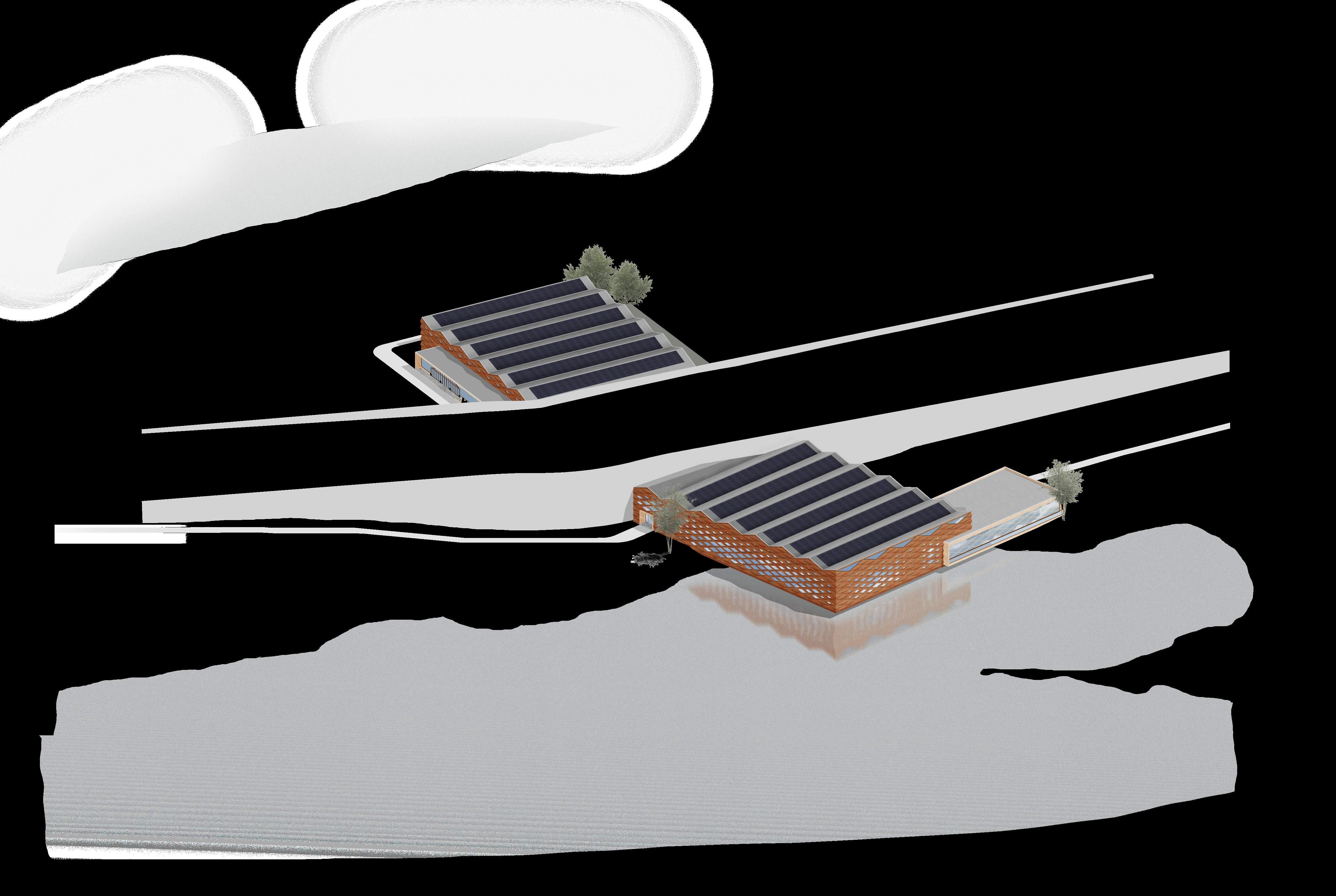
Linking two existing high points on site with a sweeping form, elevating topography above the future programmatic building. The idea is to create intervening spaces with compact fill, allowing vegetation to flow over the structure, seamlessly blending nature and architecture.
Creating an Impact
Refined a design based on two angles outlined in the prior diagram. These angles converge, forming two reflexive angles on the south and northern sides. Leveraging these angles later, they’re manipulated to influence circulation patterns effectively.
ControlledEnvironment
Finalizing the Sault Green-way
Expanded the architectural form to harmonize with existing high points, facilitating a smooth transition between elements. This integration adheres precisely to ADA’s 1:12 slope requirement, ensuring accessibility and aligning with the rigorous standards of the LBC.
Program Rotation Dynamics
Similar to step 2, the building program underwent rotations to complement the greenway above and ensure future functionality. Angle variations correspond to intended engagement, prioritizing the human-oriented elevation with the most obtuse angle.
Punctured Forms Fusing Landscape and Program
With the mass finalized, the building program intersects the greenway, suggesting integration with the landscape. This integration creates a visual flow, seamlessly blending the structure with the site.
Developing Programmatic Layout
During program development, analysis of the greenway’s impact and on-site circulation was paramount. Program parameters were influenced by considerations such as shadow patterns, the relationship between the Sault Greenway and Ashmun Addition angles, and other relevant factors.
Designated Entry Points
Each program features independent entry points, ensuring operational autonomy. This design allows for individual functionality; if one program is inactive, others can remain operational without reliance on each other.
Internal Sun-Court
Refined a design based on two angles outlined in the prior diagram. These angles converge, forming two reflexive angles on the south and northern sides. Leveraging these angles later, they’re manipulated to influence circulation patterns effectively.
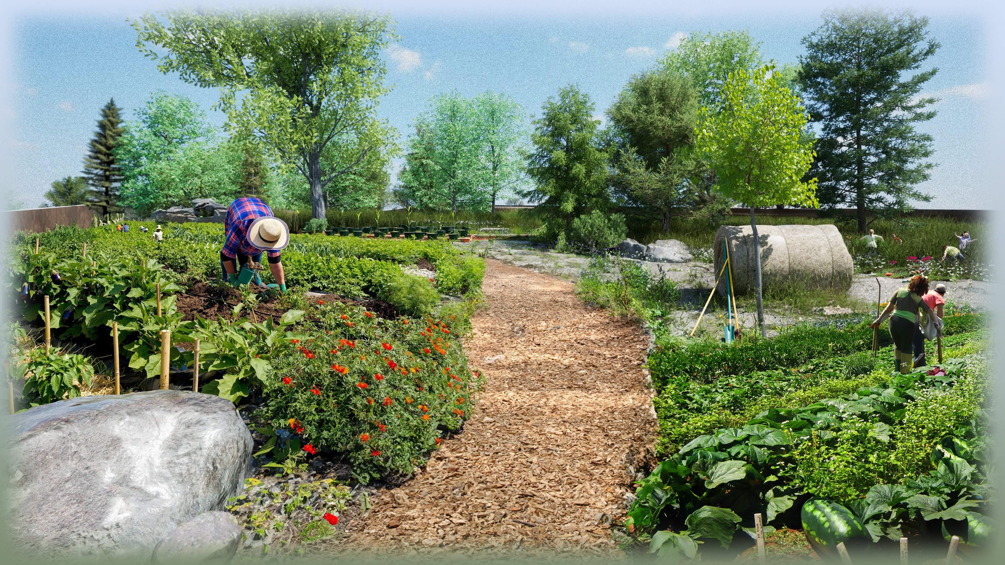
Much Needed Landscaping
Landscaping creates leveled planes, defining high and low points of the Sault Greenway, prioritizing rainwater management and retention. ADA accessible pathways are integrated into the slopes, allowing trails to flow over the form.
Photovoltaic Considerations
To optimize solar collection, photovoltaic panels will be installed at 15-degree pitches, ensuring efficient utilization of sunlight. Segments are determined by structural bay and organization.
Material Development Applying an Enclosure System


One concern of this project is the construction by, or over, either the flood plain or a marshy area. This can be corrected by meeting an “exception.” Because of this, the footprint over this region is greatly reduced.
PLACE
Ecology of a Place 03
“All projects must avoid building on pristine greenfield, wilderness, prime farmland or in a floodplain unless they meet an exception.”

Structure pulls environment up, and around program. This creates an extension of the natural environment substituting the footprint.
PLACE
Habitat Exchange 03
“All projects must set aside land equal to the project area (or 0.4 hectares/1 acre, whichever is greater)10 away from the project site”
This program centers all views to overlook the surrounding park. This ties nature and the interior conditions.
BEAUTY
Beauty & Biophilia 19
“Projects must be designed to include elements that nurture the innate human/nature connection. Each project team must engage in a minimum of one all-day exploration of the biophilic design potential for the project.”
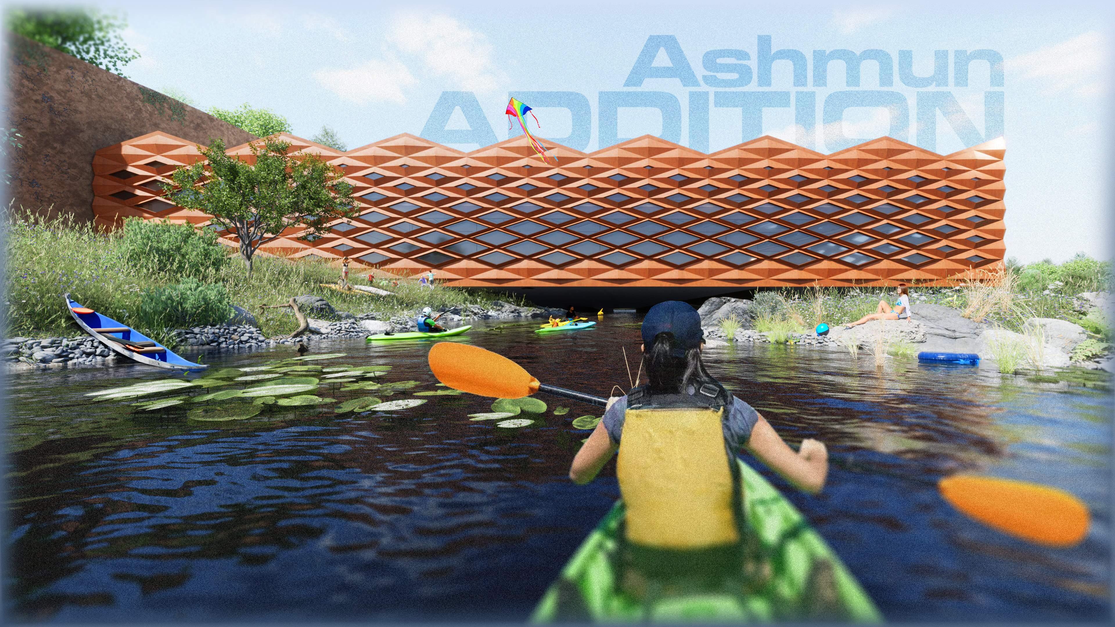
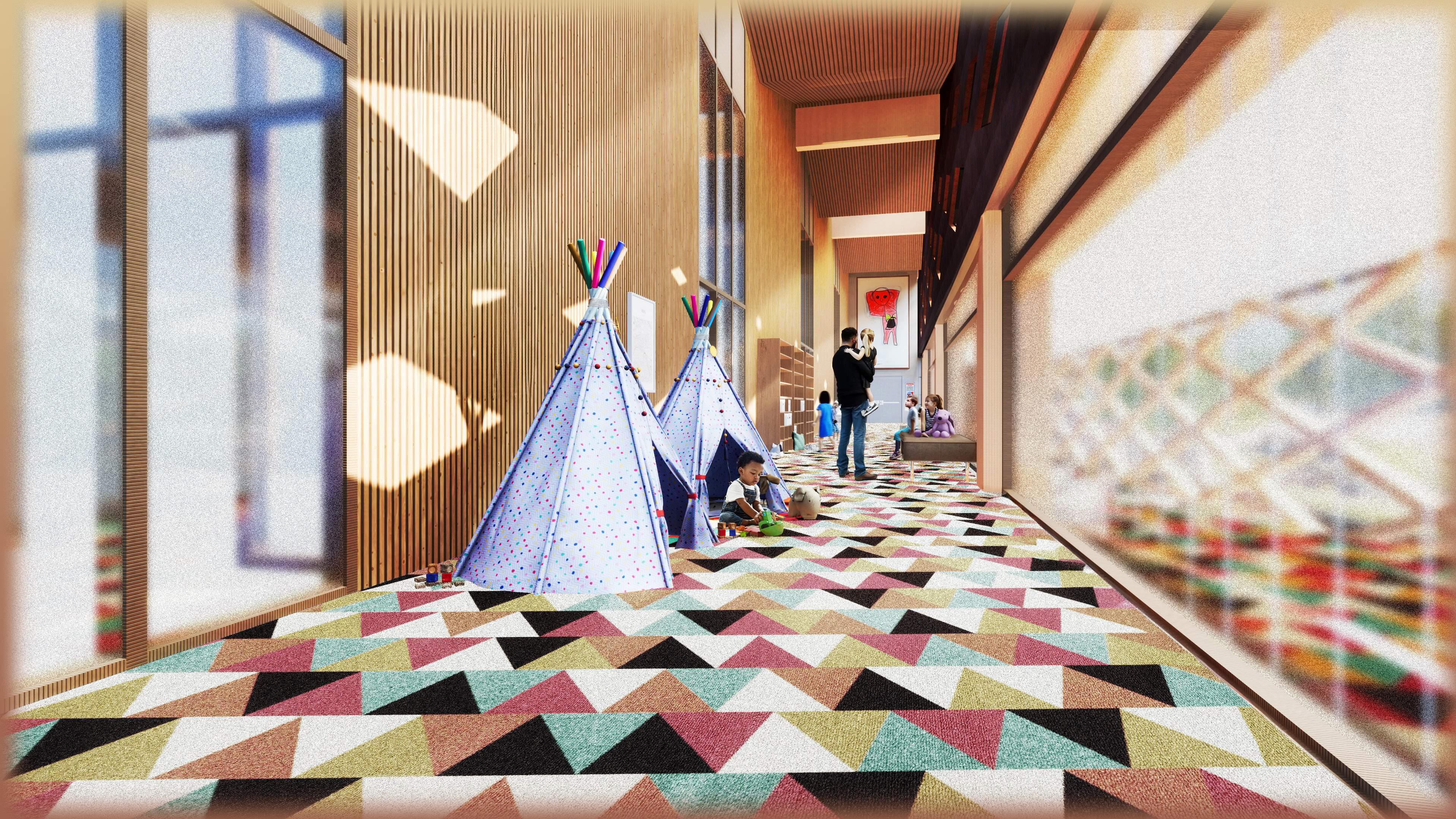
Fun Under The Sun
Anjelo Hana
Anjelo Hana
Anjelo Hana
Anjelo Hana
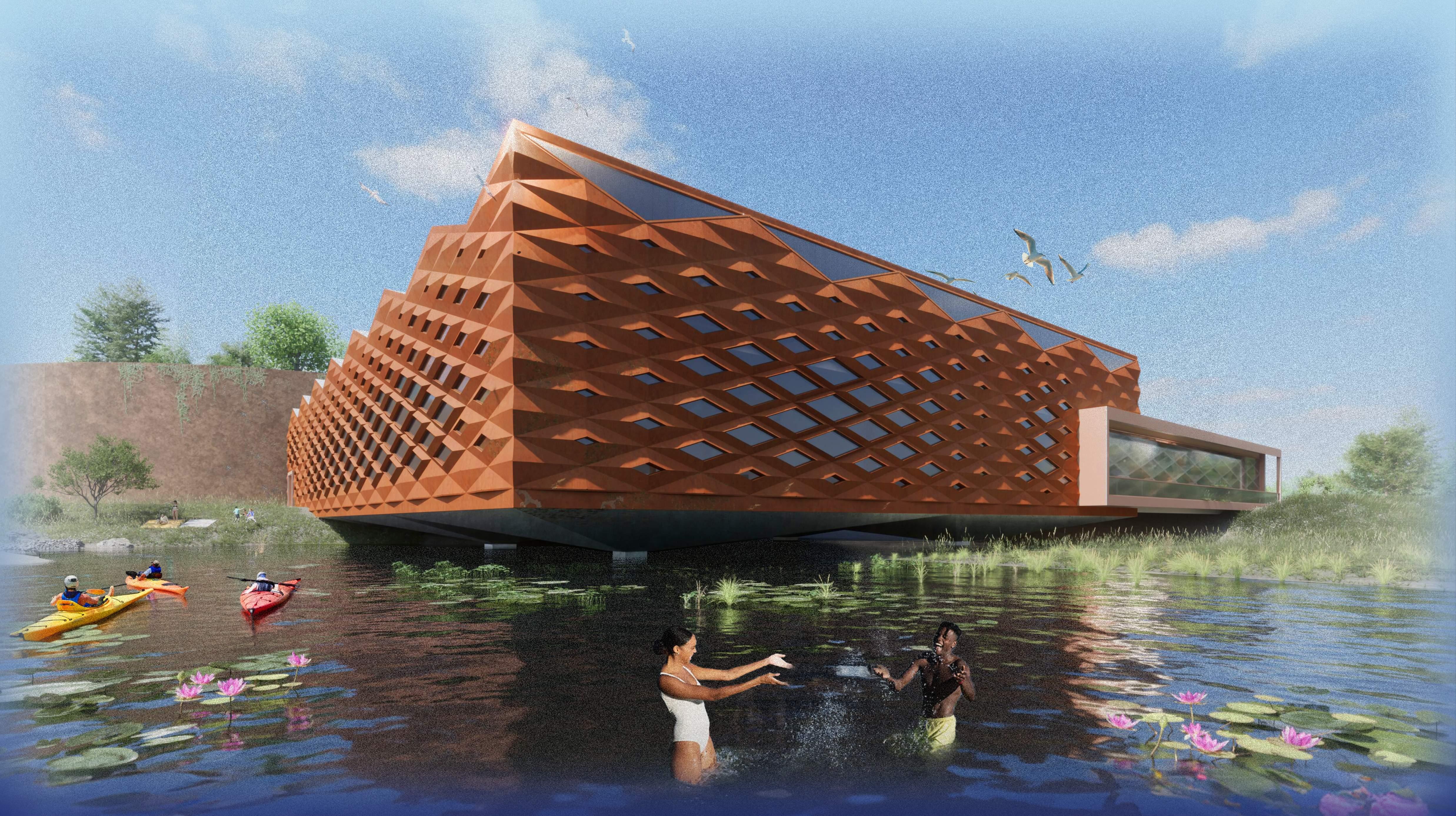
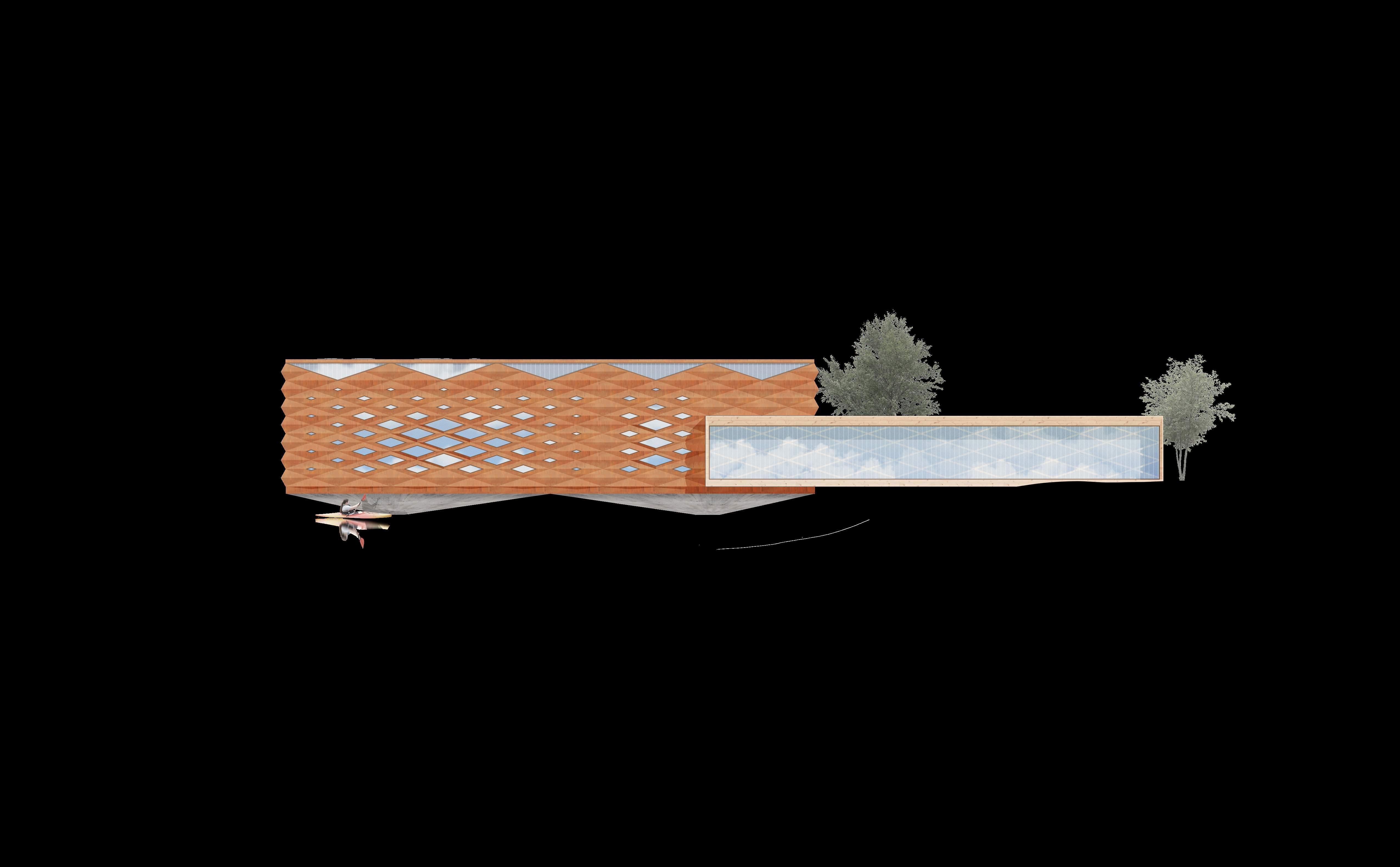
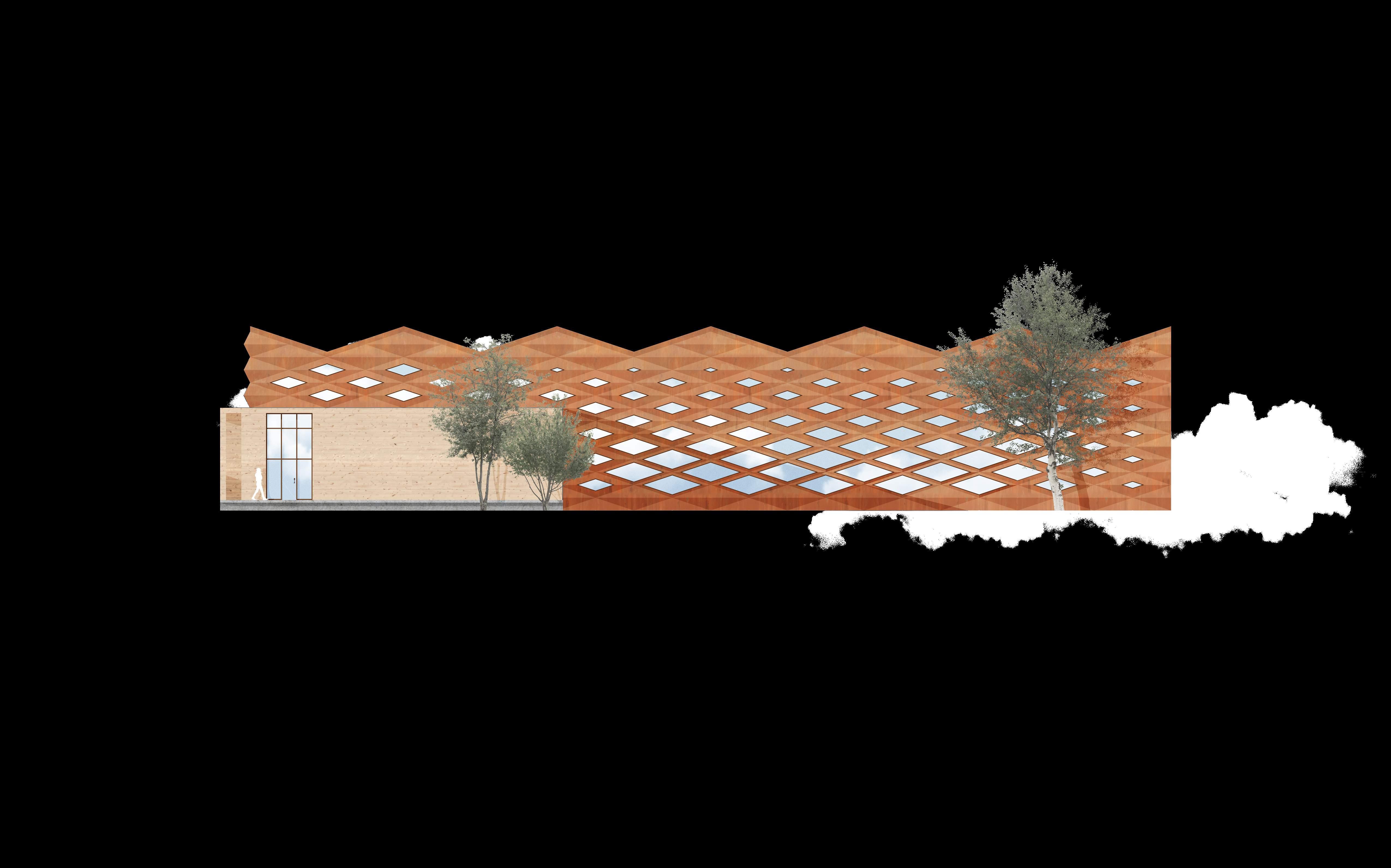
Final Building Design

Refer to Page #36, “CLT Diagrid Panel System,”
All retention walls are made of panelized Fiber Cement cladding stylized to mimic natural sandstone, pulling reference from local geology.
cement is considered more environmentally friendly than vinyl because it’s made from more sustainable materials and doesn’t release toxic VOCs during manufacturing.”

Exterior points of entry, as well as facades surrounding lobby spaces, are typically CLT Panel systems.
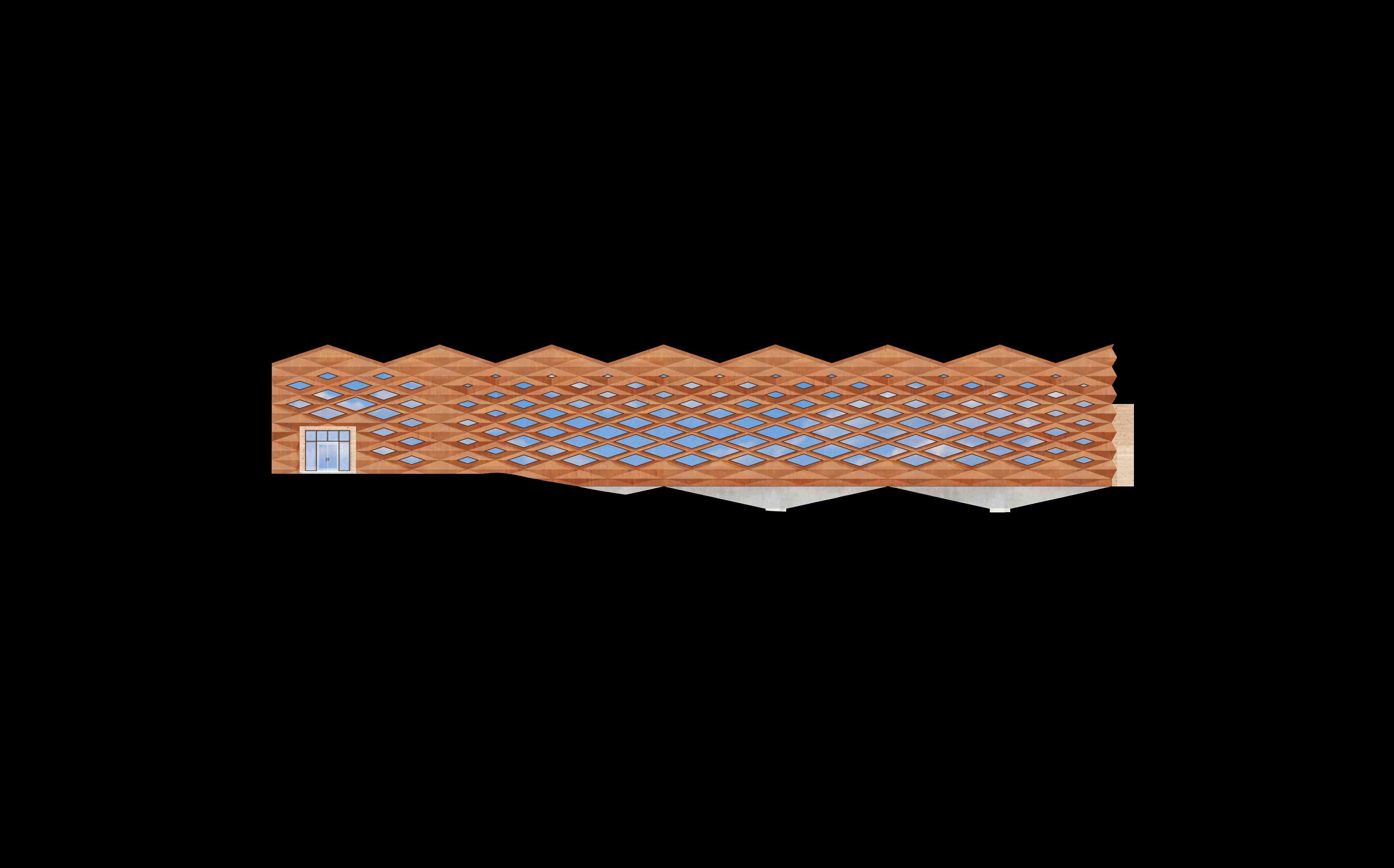
“TerraLam CLT panels are manufactured in Phoenix, Illinois, and Lufkin, Texas with #2 or better southern yellow pine laminations in the major and minor directions.”
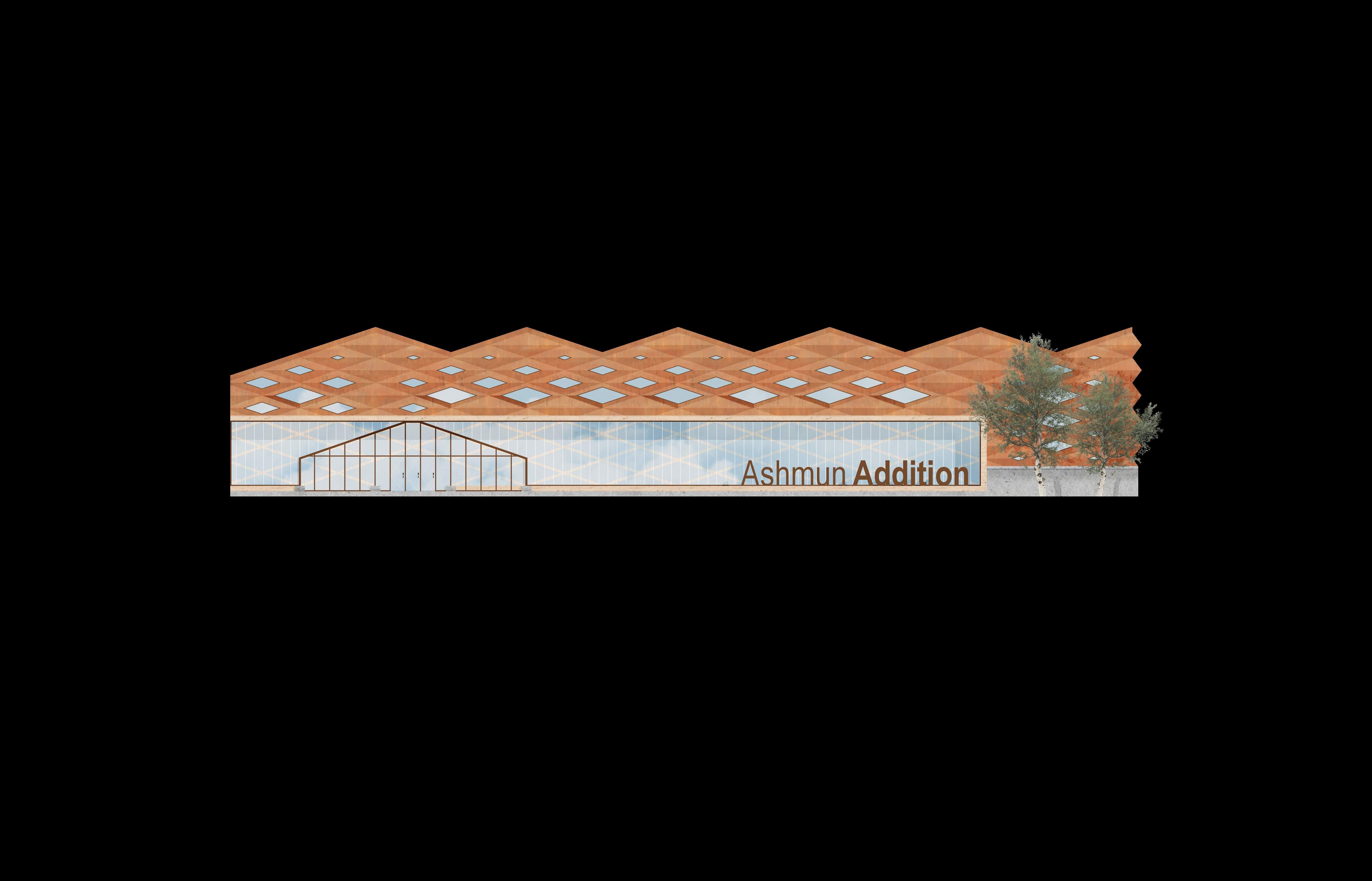
All retention walls are made of panelized Fiber Cement cladding stylized to mimic natural sandstone, pulling reference from local geology.
“Fiber cement is considered more environmentally friendly than vinyl because it’s made from more sustainable materials and doesn’t release toxic VOCs during manufacturing.”
Exterior points of entry, as well as facades surrounding lobby spaces, are typically CLT Panel systems.
CLT panels are manufactured in Phoenix, Illinois, and Lufkin, Texas with #2 or better southern yellow pine laminations in the major and minor directions.”
Steel Wrapped Panels
All retention walls are made of panelized Fiber Cement cladding stylized to mimic natural sandstone, pulling reference from local geology.
“Fiber cement is considered more environmentally friendly than vinyl because it’s made from more sustainable materials and doesn’t release toxic VOCs during manufacturing.”
Exterior points of entry, as well as facades surrounding lobby spaces, are typically CLT Panel systems.
CLT panels are manufactured in Phoenix, Illinois, and Lufkin, Texas with #2 or better southern yellow pine laminations in the major and minor directions.”
Prefabricated
All retention walls are made of panelized Fiber Cement cladding stylized to mimic natural sandstone, pulling reference from local geology.
“Fiber cement is considered more environmentally friendly than vinyl because it’s made from more sustainable materials and doesn’t release toxic VOCs during manufacturing.”
Exterior points of entry, as well as facades surrounding lobby spaces, are typically CLT Panel systems.
“TerraLam CLT panels are manufactured in Phoenix, Illinois, and Lufkin, Texas with #2 or better southern yellow pine laminations in the major and minor directions.”


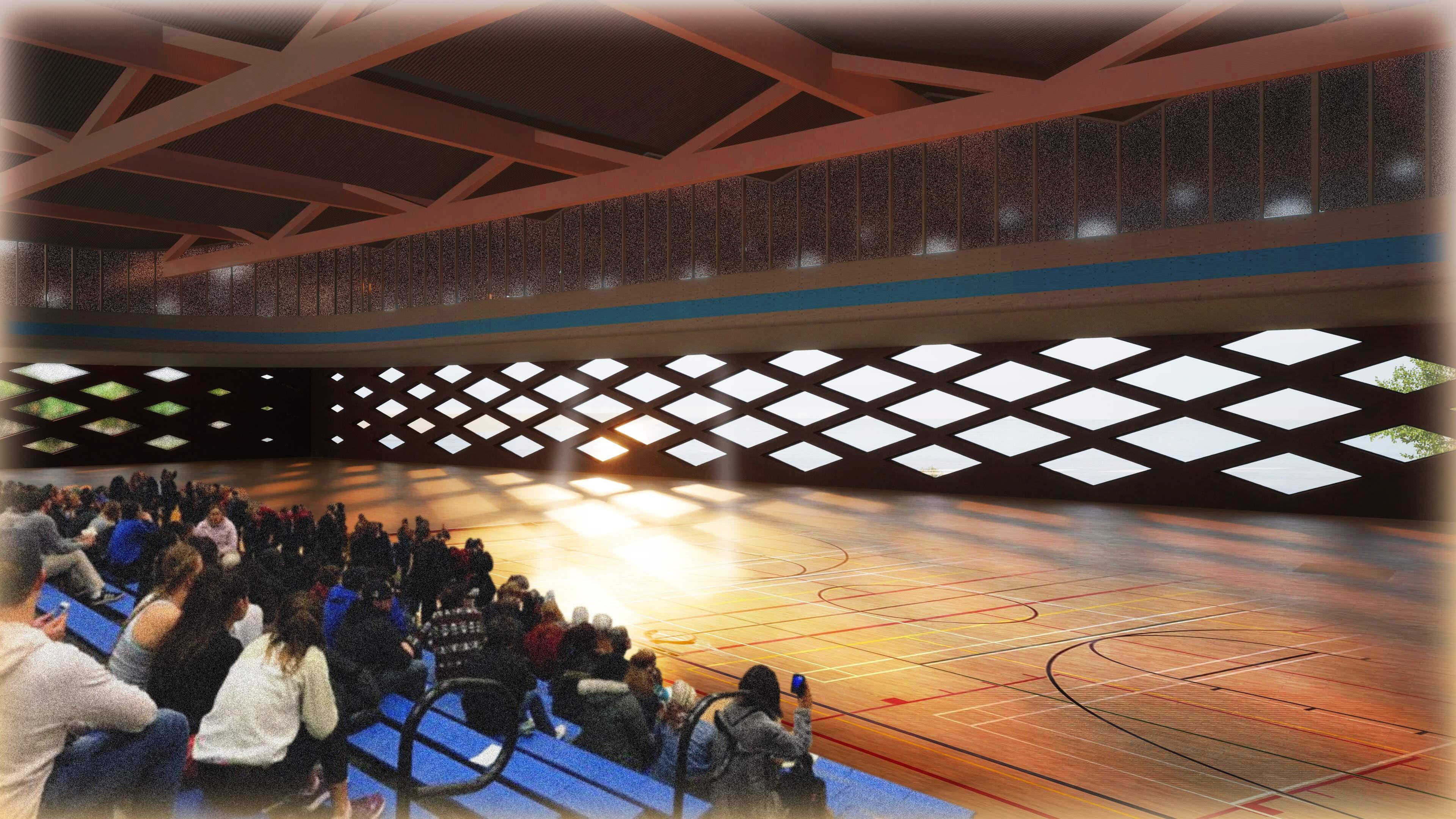
CurlingArenaLobby CurlingArena
Community at The Heart
Anjelo Hana
Anjelo Hana

Anjelo Hana
Building Systems & Technical Information
H-VRF systems are reliant on a local water source to provide the main source of heat transfer for a system. The source of water changes based on the period throughout the year, finding the best sourced water based on average temperatures.
Second phase for water circulation. Water and refrigerant levels are distributed through this component -sending predetermined quantities based on the ideal temperature per VRF cassette.
Hydronic Branch Converters - in comparison to a typ. VRF sys. use 30% less refrigerant charge overall with 70% less Embodied Carbon. This is caused by a swap from VRF’s typ. Refrigerant- R410A to VRFR32
Given the placement of the building, directly sourcing water form Ashmun Bay to supplement HVAC water needs is plausible. During warmer months, the building will be pulling water into the first series of tempered water tanks - then distributing it throughout the building into an underground storage tank.
During the warmer seasons, Ashmun bay - or largely Lake Superioraverages ~ 60°-65° during peak summer months. This temperature allows the VRF system a good baseline - nearly room temperature - to adjust the water’s temperature (lowering needed Refrigerant Charge).
Great Lakes Integrated Sciences and Assessments (GLISA)
Recycled Water Input Stored Water Input
During cooler seasons, the system relies purely on stored water - at least until all stored water is used. This insures water at a naturally geothermal temperature ~50° is pumped through the system, lightening the electric load needed to temp. The water. .0A .0B .0C
Recycled water as an input refers to the water going through the return pipes of the VRF system. This water would be discharged into a differing water tank from the initial tank introduced in phase A (refer to diagram). This system simply moves water through a consistent loop, with occasional new input added to the system based on need.

Water intake valves directly collecting water either from site, or Ashmun bay. Water is brought to a tempered water tank, bringing it to room temperature ~68°-70°
55° is the Average Temperature of Lake Superior annually. This number would fluctuate.
The Outdoor Unit, specifically an Energy Recovery Ventilation (ERV) system in this proposal, directly provides refrigerant (Yellow Line) to the Hydronic Branch Converter.
The Carrier Compact 4-Way Cassette provides supreme comfort by delivering conditioned air flow in four directions while fitting a standard T grid ceiling.
The 40VMC fan coil is matched with the 38VMR heat recovery or the 38VMH heat pump and the 40MV9 series controllers. Compatible Outdoor Units & Controls
The Carrier VRF One-Way compact cassette provides supreme comfort delivering conditioned air flow and ideal space coverage. The unit has a slim and compact design, ideal for any solution in which ceiling space is limited
Compiled Systems at a Glance
Advanced Cladding Solutions
The enclosure system is composed of a prefabricated Cross Laminated Timber (CLT) unit. These units join at the nested fins, ensuring a moisture barrier suitable to protect the 5-ply CLT slabs. These units join on the interior via a series of undetermined structural thermal break materials - to ensure stability and thermoproperties.
Anjelo Hana
Mass Timber Joinery
The enclosure system and secondary structural system synthesize at coordinated points every 30’ - Approx every other 3 panels. These panels follow a similar assembly to the previously mentioned panel system - also coming prefabricated. The largest difference being the intersection of the GLT beam, and the CLT slab. All of this neatly packed within the corten steel sheathing, hiding a series of steel fasteners.
Anjelo Hana
Mass Timber Joinery
The enclosure system and secondary structural system synthesize at coordinated points every 30’ - Approx every other 3 panels. These panels follow a similar assembly to the previously mentioned panel system - also coming prefabricated. The largest difference being the intersection of the GLT beam, and the CLT slab. All of this neatly packed within the Corten Steel sheathing, hiding a series of steel fasteners.
Anjelo Hana
Utilizing Intensive Wall Assemblies
U305 was selected as a barrier between HVAC zones due to its addition of common insulators between the stud systems. The fire ratings also provide extra safety for egress concerns.
1 layer 5/8” [15.9 mm] Sheetrock® EcoSmart Gypsum Panel (UL Type ULIX™)
1 layer 1/2” [12.7 mm] resilient channel, 25 ga. (0.018”), 24” [610 mm] O.C
1 layer 2” x 6” [38 x 140 mm] Steel stud w/ 1 1/2” X 4” perforations, 16” [406 mm] O.C.
1 layer 6-1/4” [159 mm] Fiberglass insulation 1
Anjelo Hana
Clustered HVAC Systems
Both supply and return run parallel in each plan, keeping continuity with design - mirroring the mass timber beam-work above. Both vents are to be supported with one trapeze hanger, stabilized with a perforated stud. This stud allows H-VRF ~1” diameter piping to be run between ductwork, which would be Wrapped with an insulation valve wrap: NOSWEAT™ VRF (Variable Refrigerant Flow) Valve Wraps


Anjelo Hana
Stud Secured VRF Piping
Within the wall systems are perforated studs, these allow for VRF piping to be run throughout the wall enclosed with an insulation valve wrap. The stud organizes valves into differing VRF cassette units, making system organization simple as well as compact.
.08