ANDREW


PORTFOLIO
MICKELSON


DAYLIT MIDTOWN
A LOCAL VORTEX
SHIFTING CONTEXTS
BOOLKLYN TOWER
SLADE ARCHITECTURE
GARRISON ARCHITECTS
BABCOCK DESIGN

UPWALL DESIGN


BODY+TIME
TROPIC PAVILION
STEEL OASIS
HABITAT K-9
PHOTOGRAPHY
GRADUATE
PROFESSIONAL PERSONAL UNDERGRADUATE


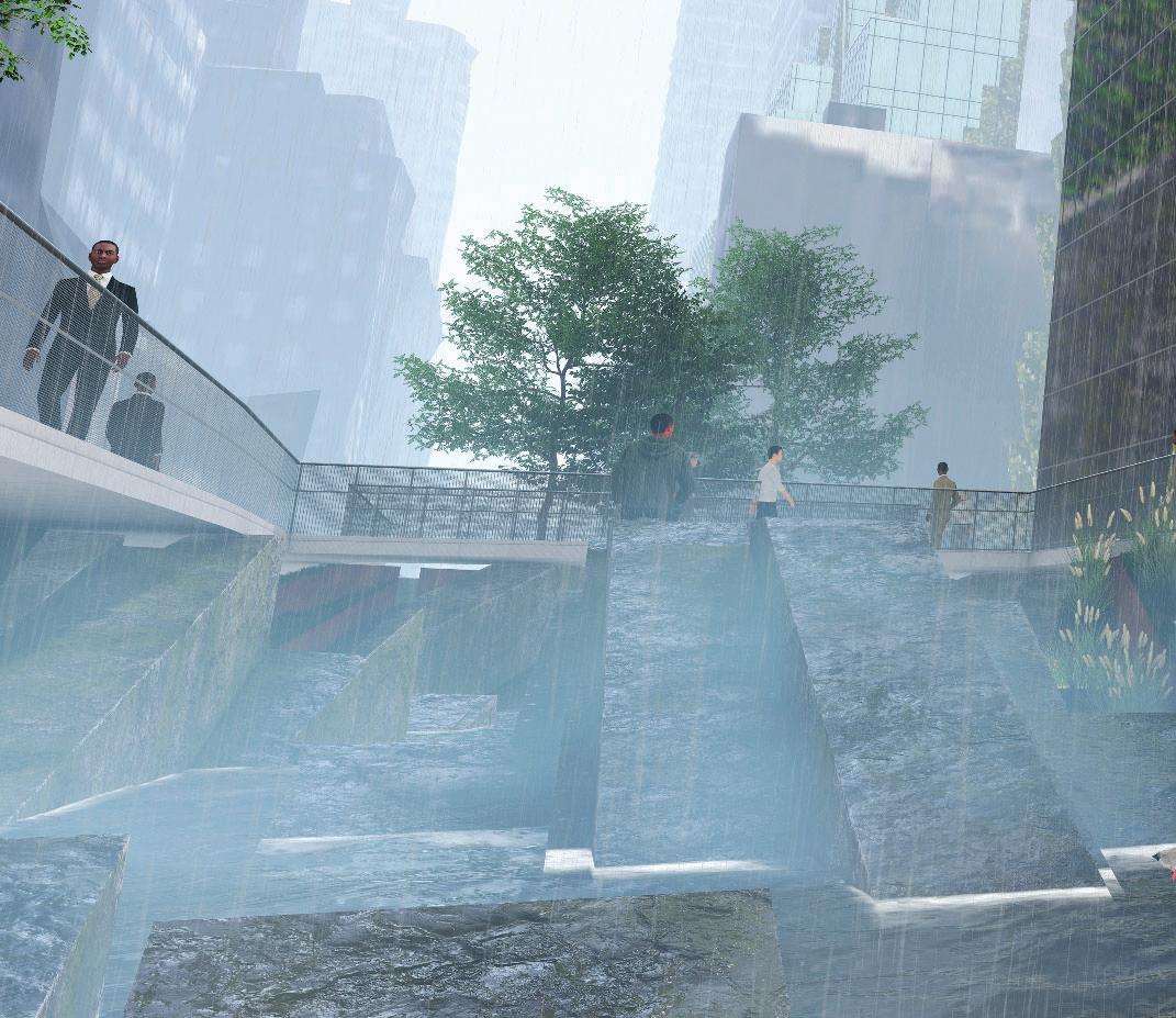
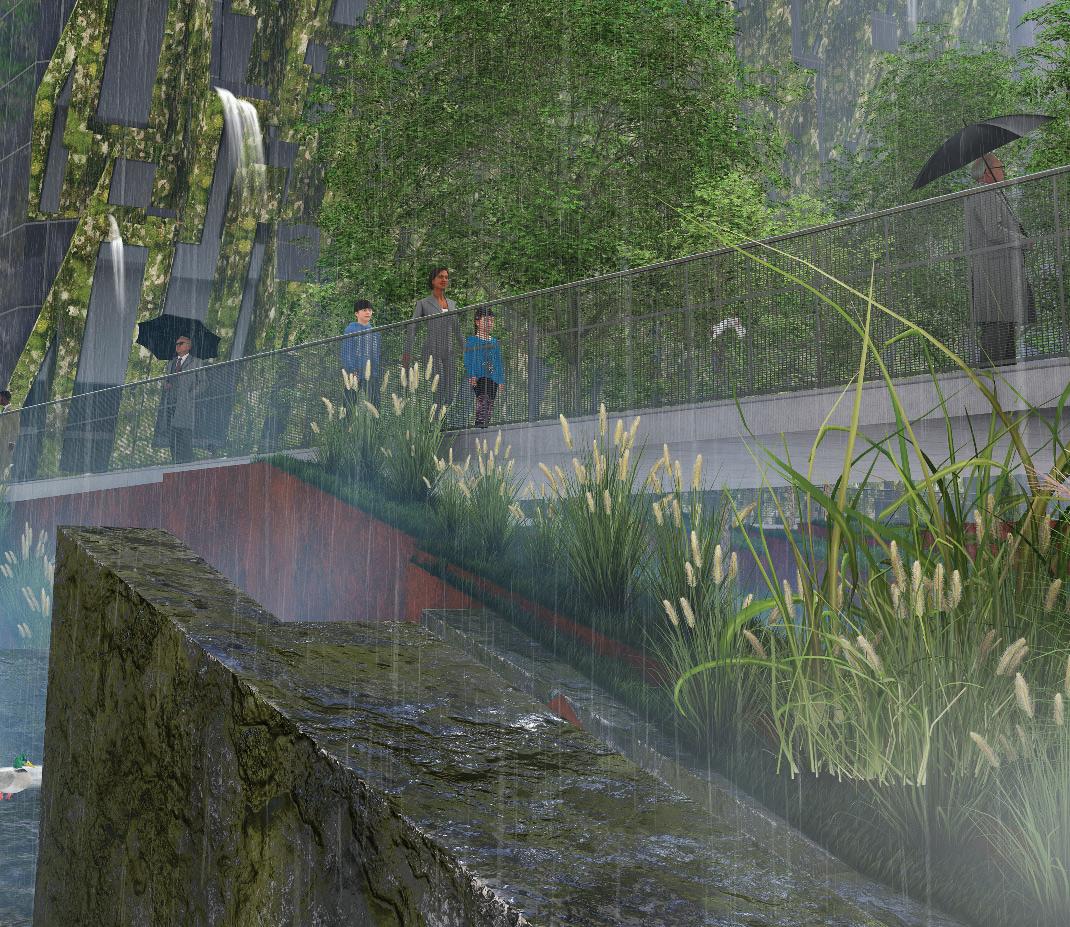


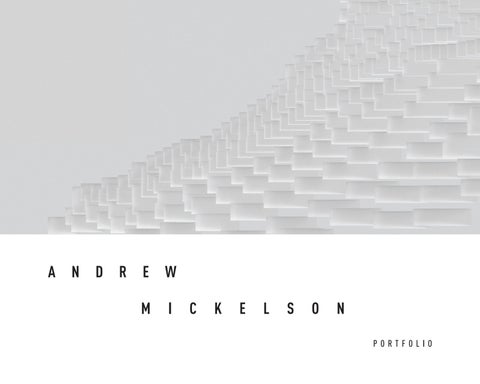
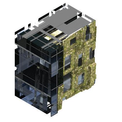
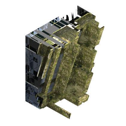
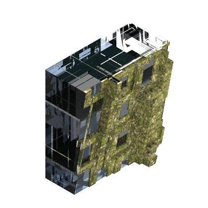
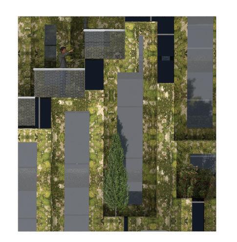
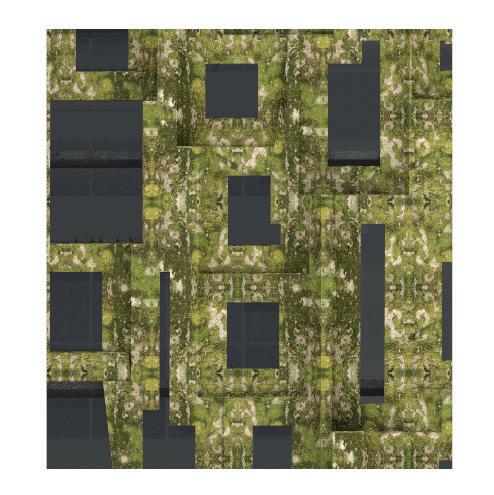
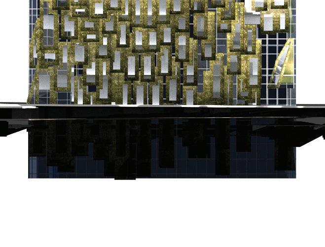
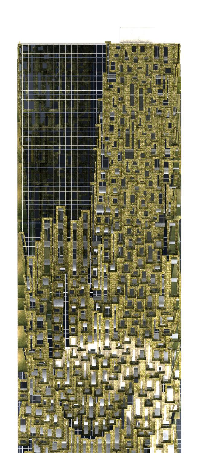
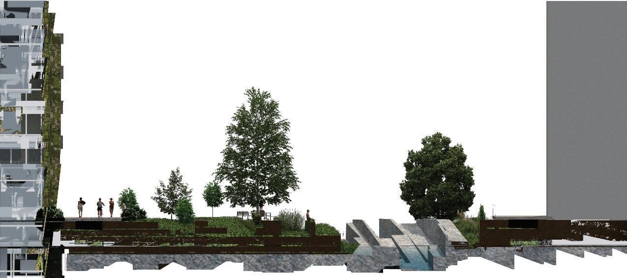
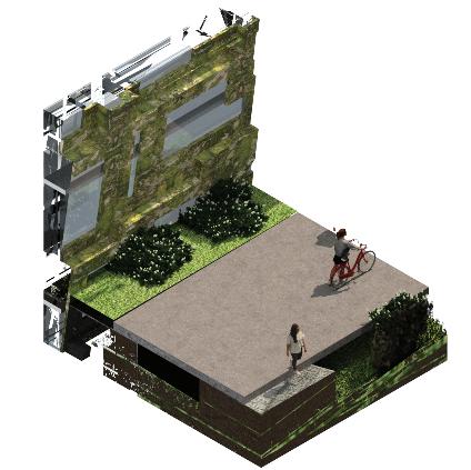
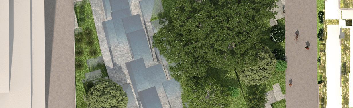
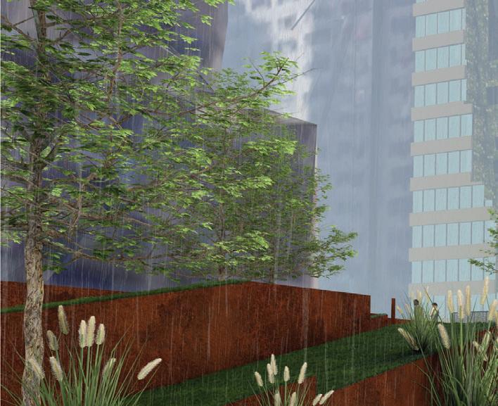
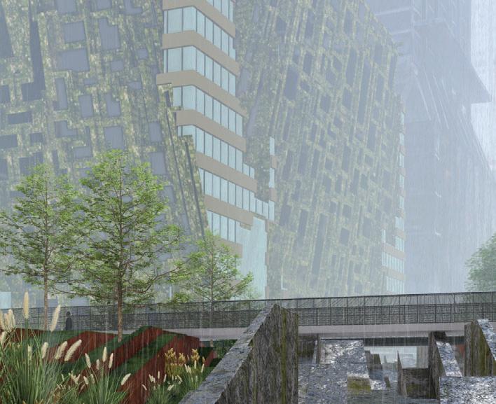
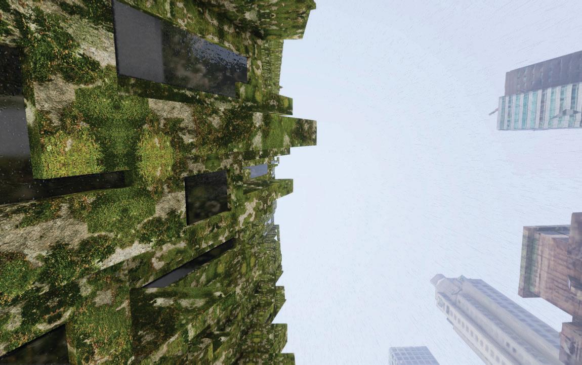
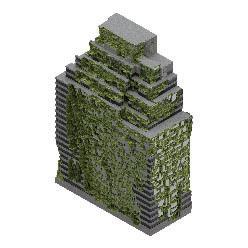
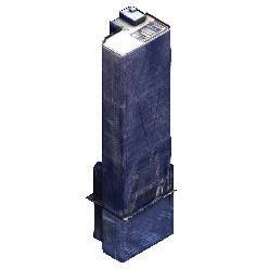
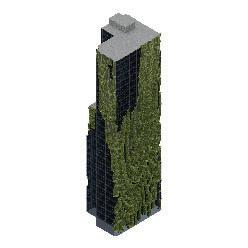
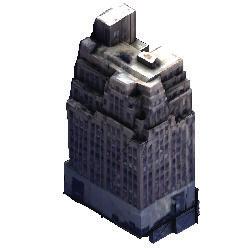
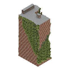
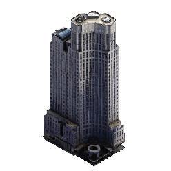
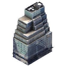
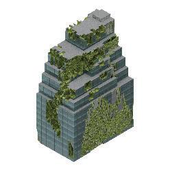
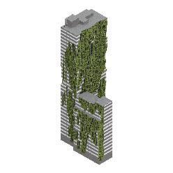
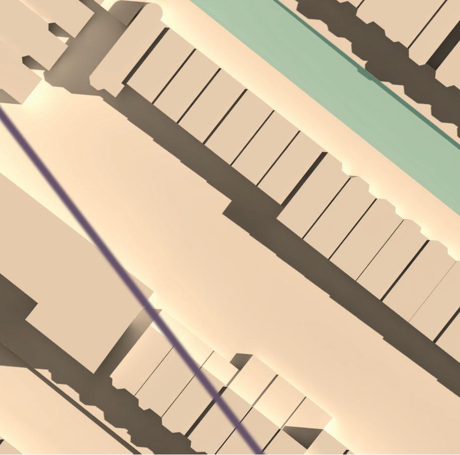
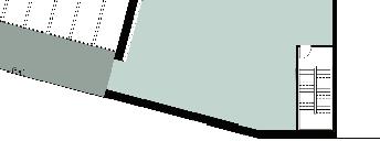
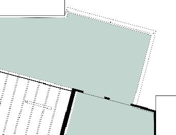
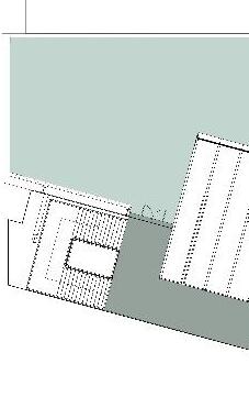
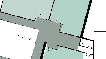
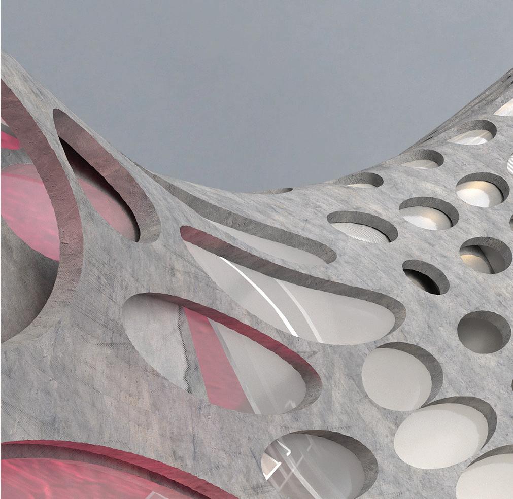
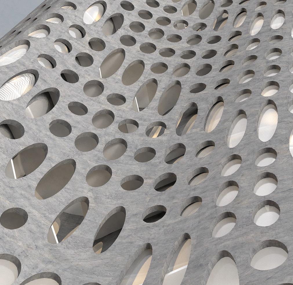
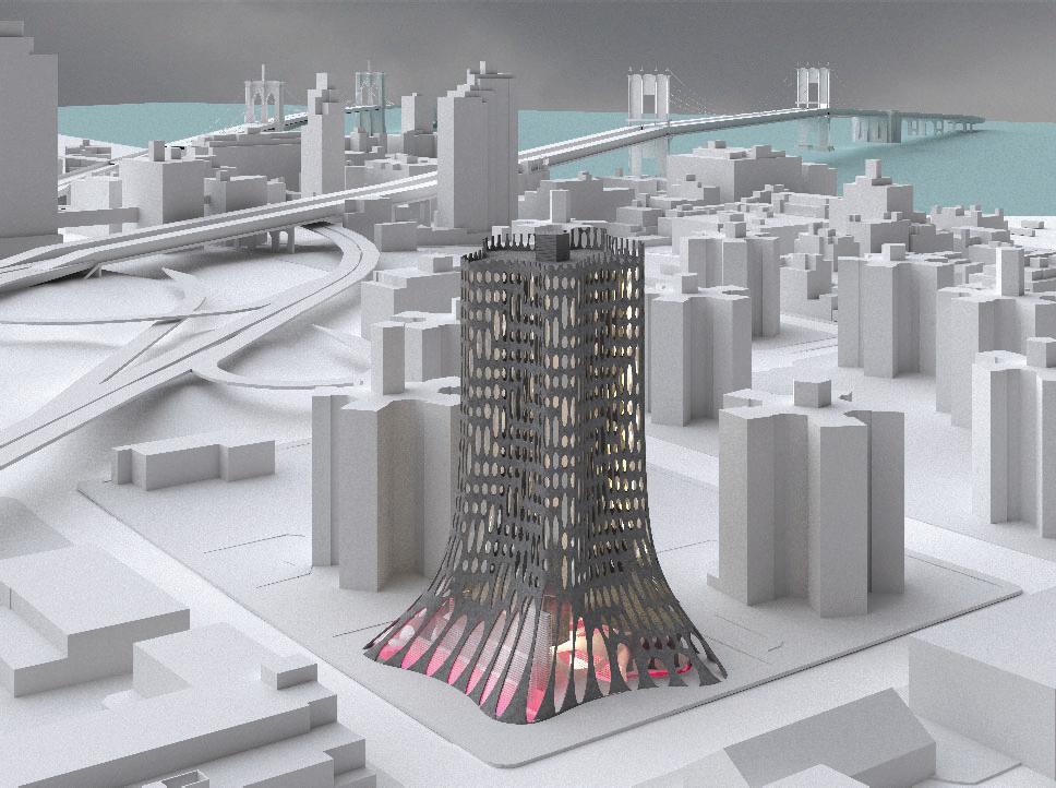
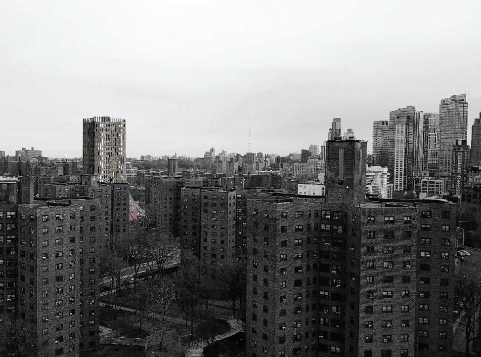
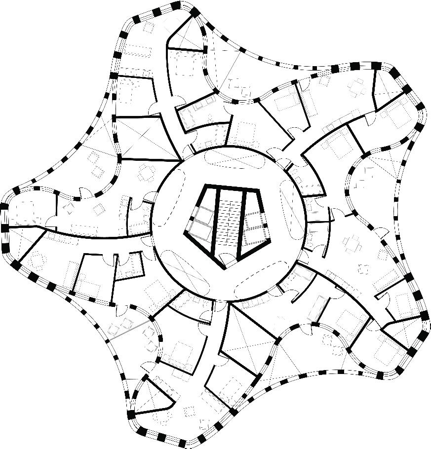
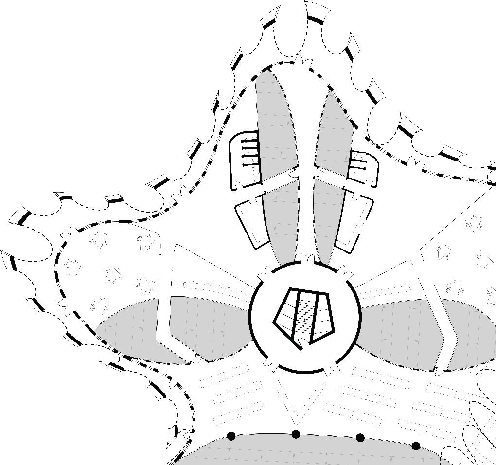
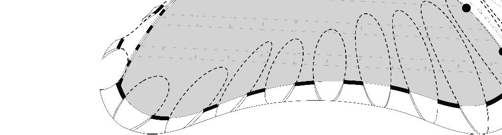
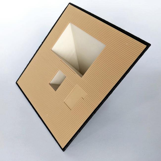
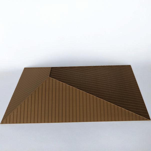
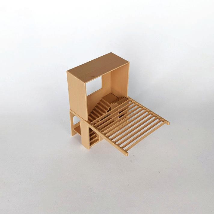
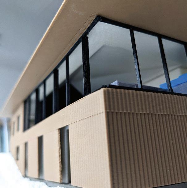
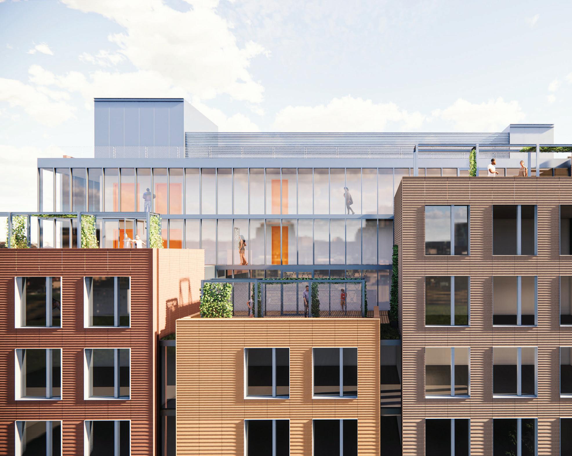
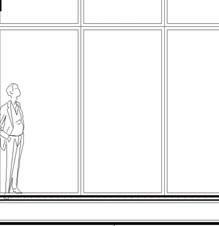
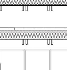
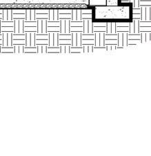
Urban commercial districts in all cities face usage crises due to accelerating changes in work-life patterns. Simultaneously, New York City and the country face a housing crisis due to a lack of (particularly affordable) housing. The reemergence of historical disparate employment lifestyles mirrors the process of daylighting entombed urban streams. Similarly, repositioning unwieldy later 20th-century office towers into homes requires, among other factors, bringing daylight farther into deep floor plates. Fractal textural subtraction derived from the city’s 1916 Zoning Resolution carves away from both aging facades and dead streetscapes. Reintroducing livability vertically and horizontally engages ecologic groups across a reanimated Manahatta biosphere: a contact zone between previously divided human and non-human inhabitants.

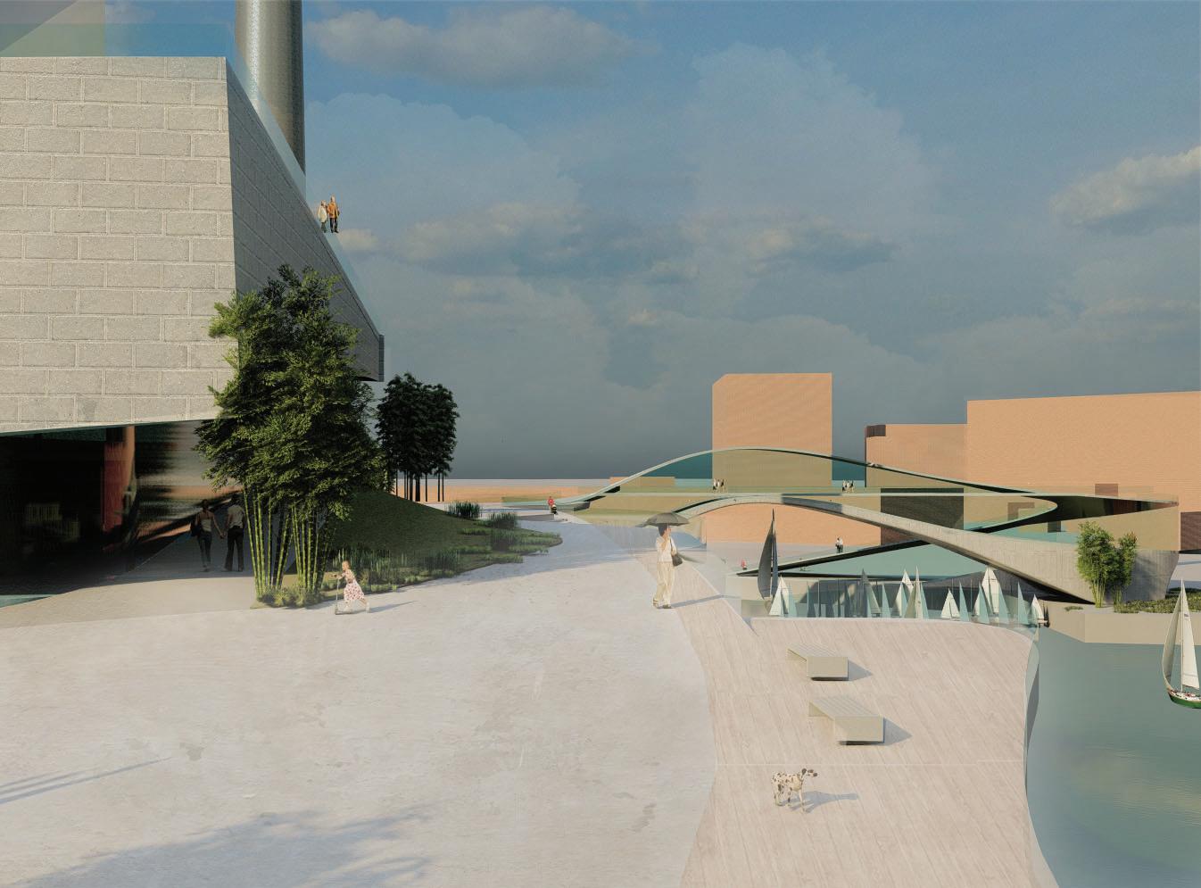
opposite: stream view
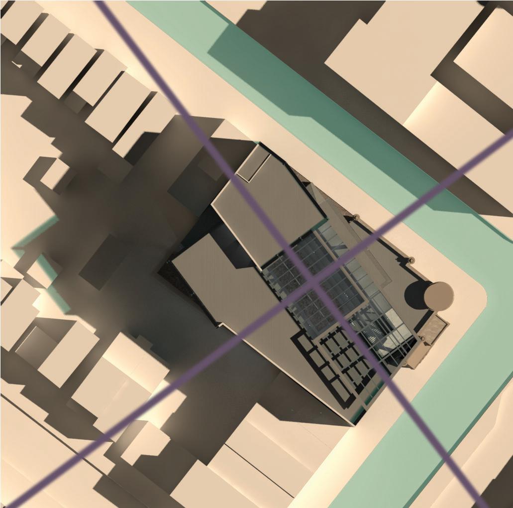
above: site analysis


right: balcony view
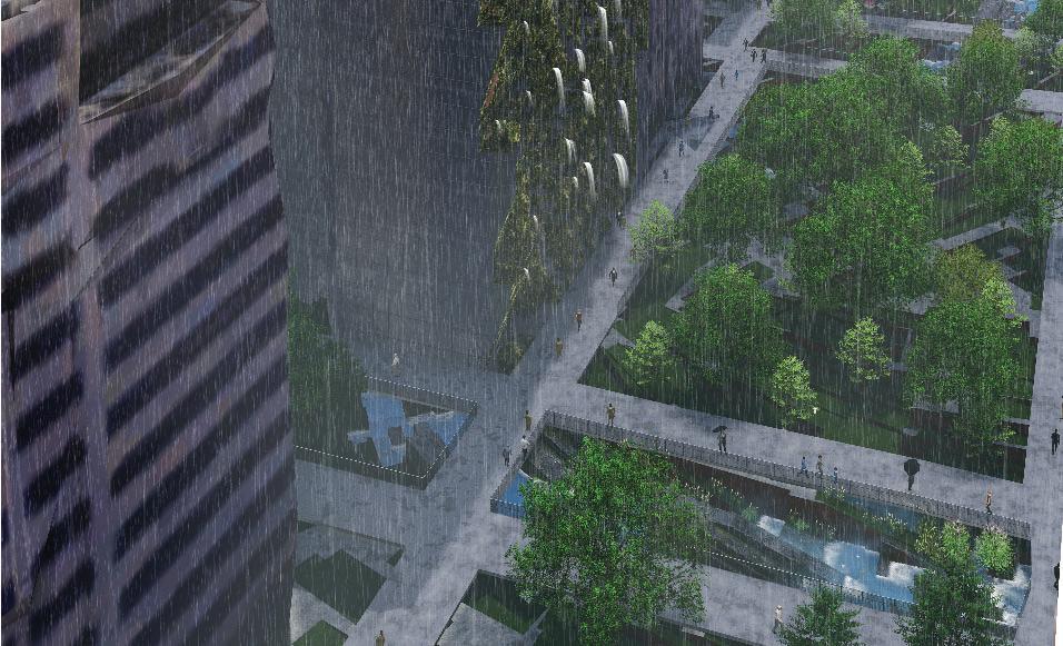
DAYLIT MIDTOWN
SULAN KOLATAN
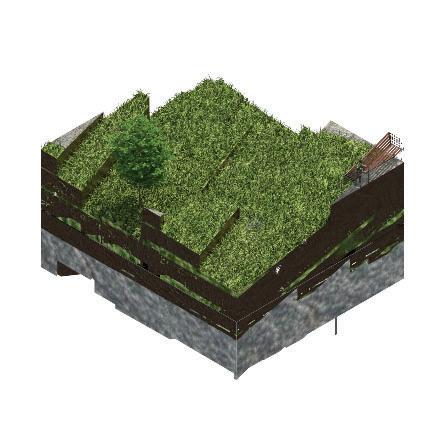
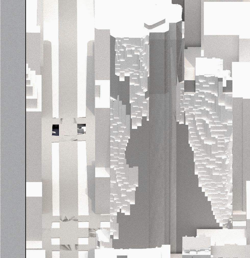
vertical textural habitation
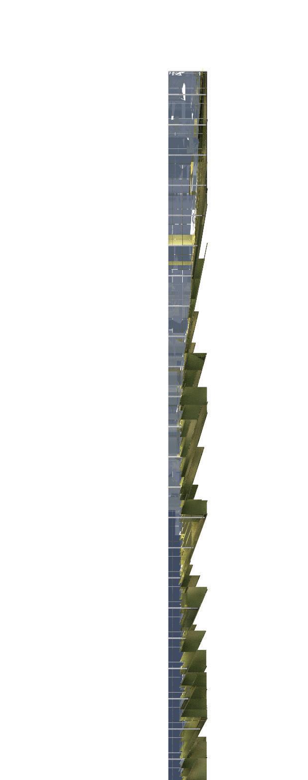
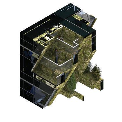
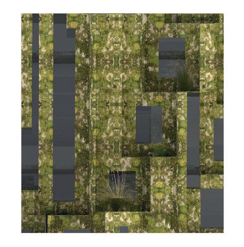
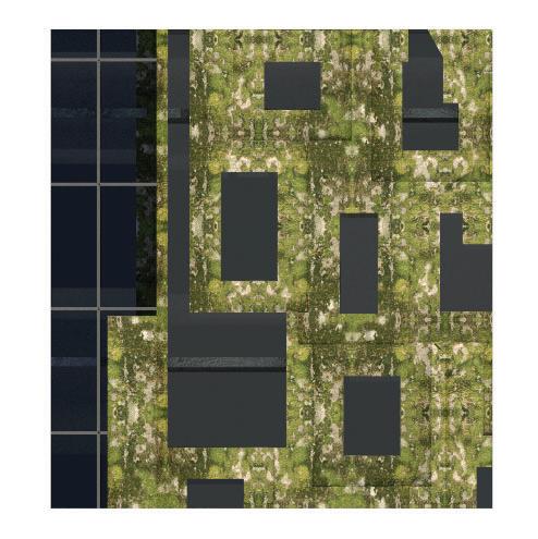
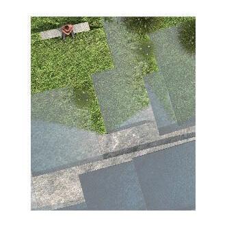
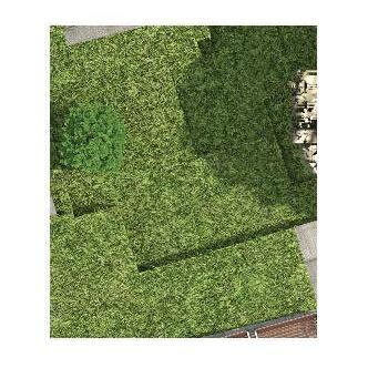
 horizontal textural habitation
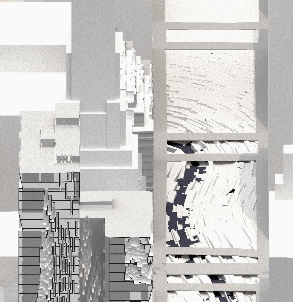

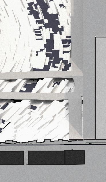
oblique site section


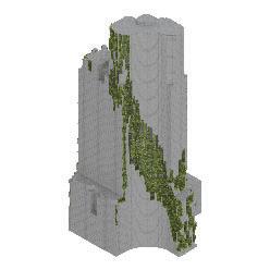
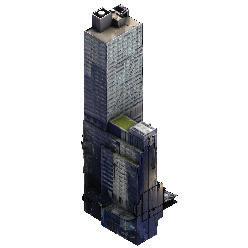
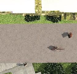
textural integration
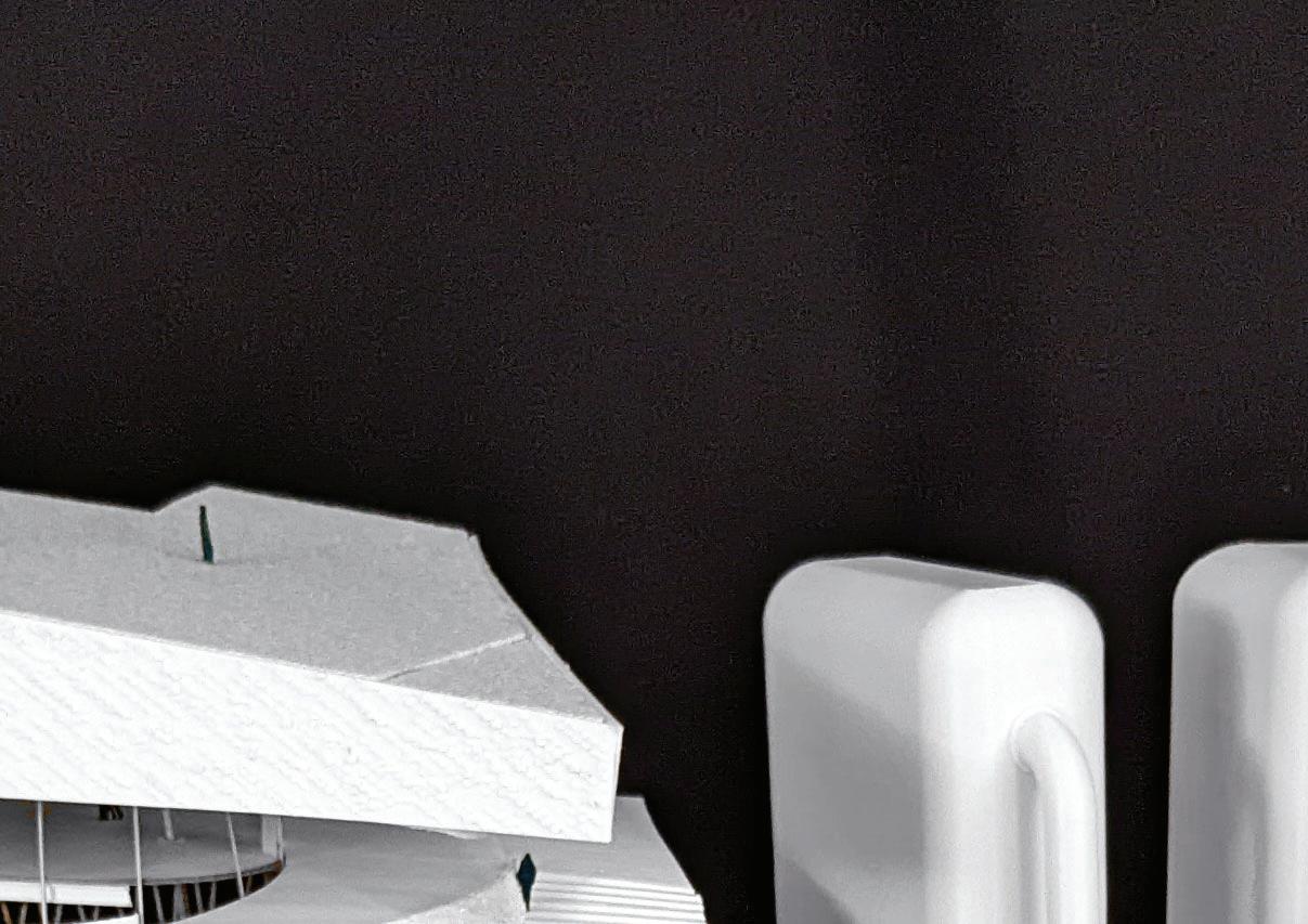

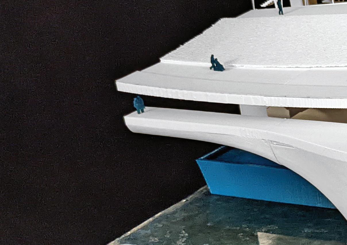
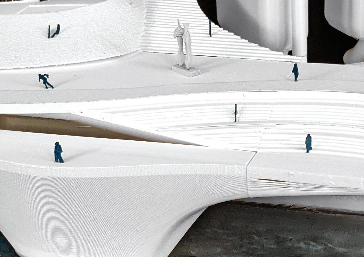
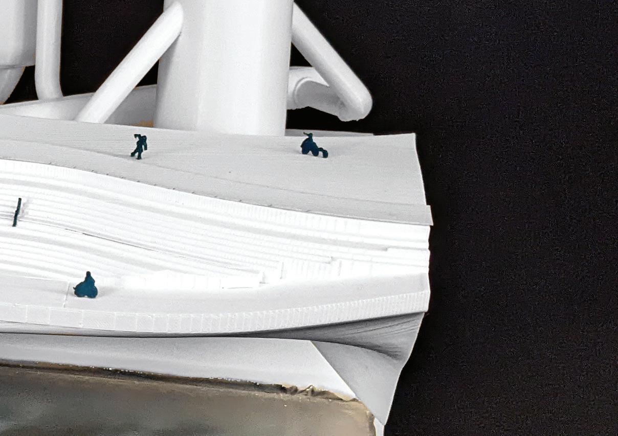


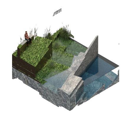
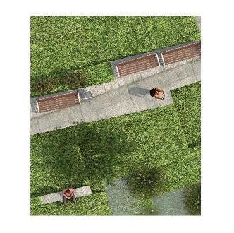
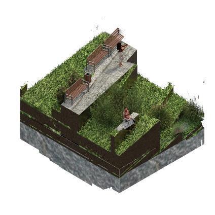
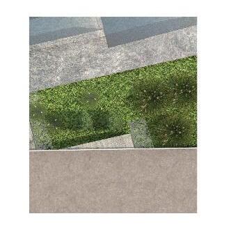
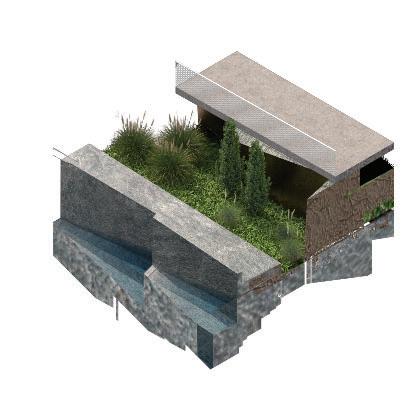
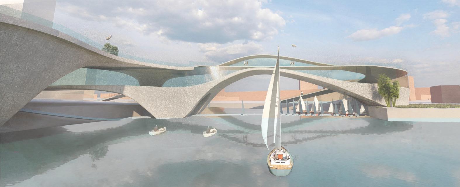
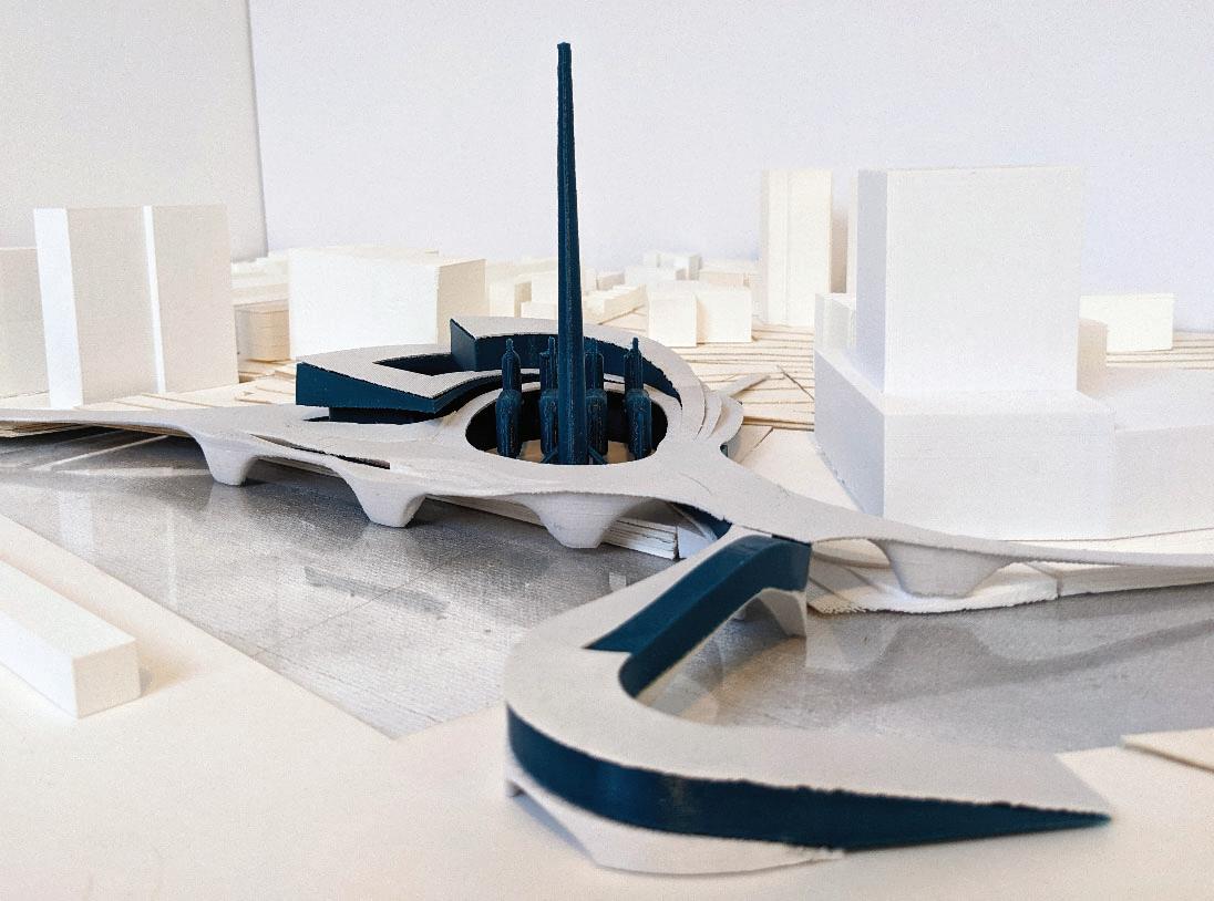
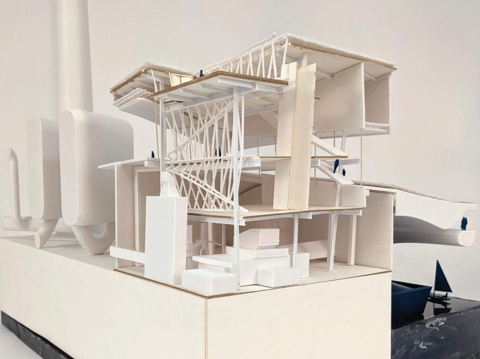
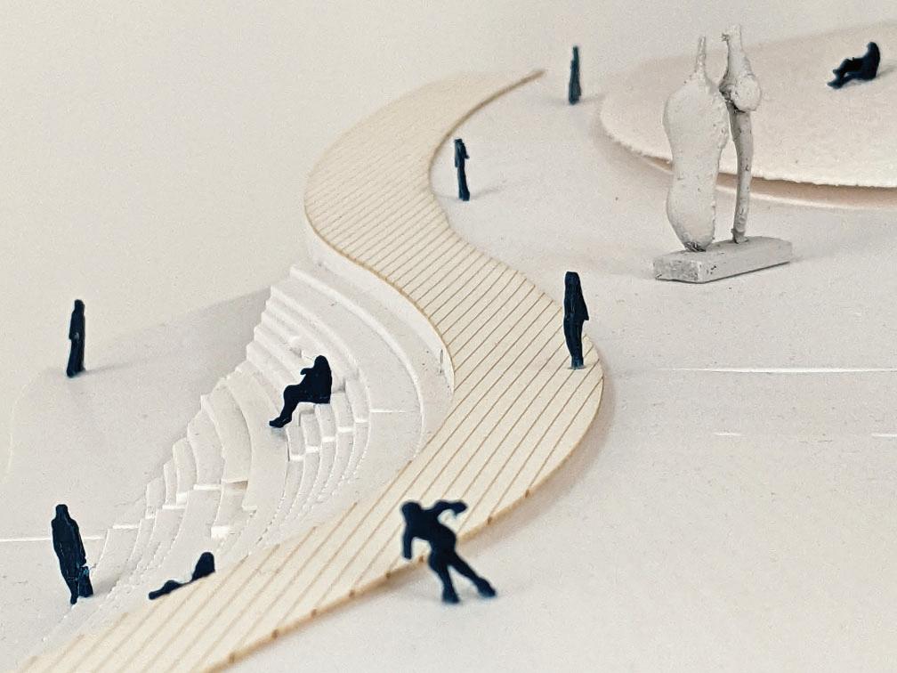
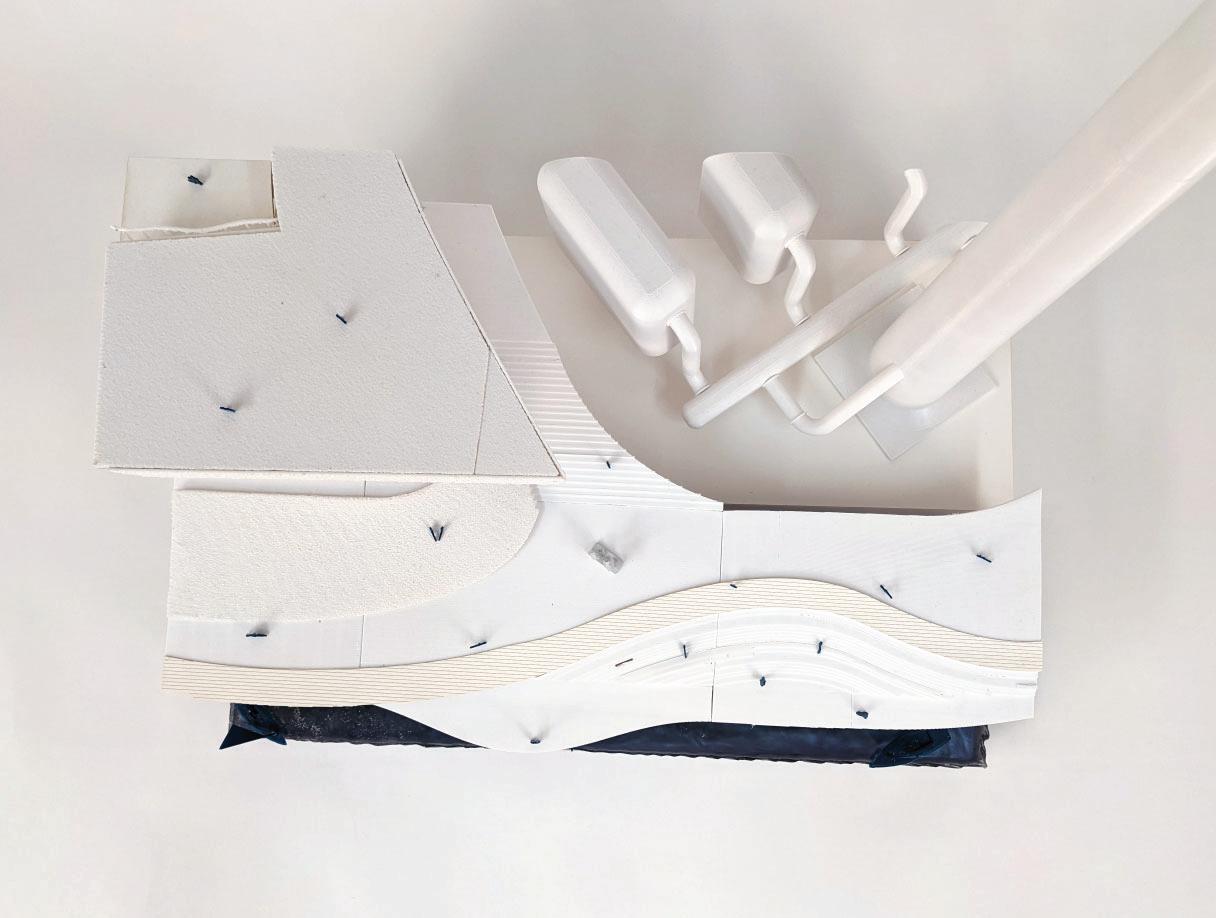
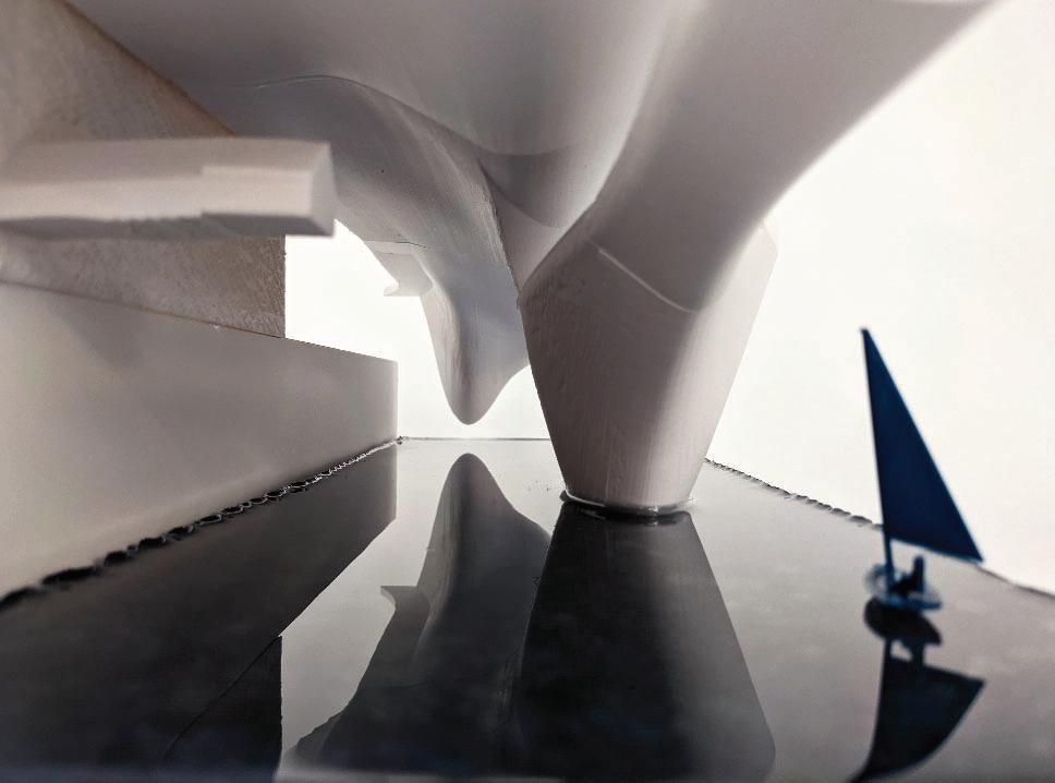
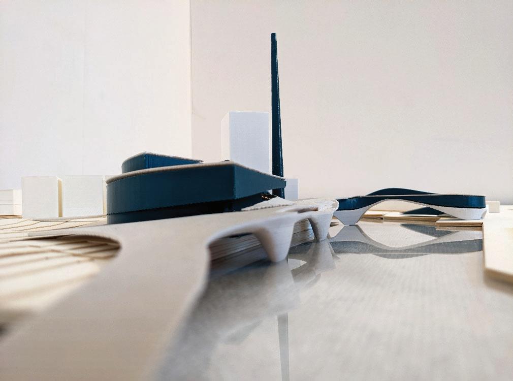
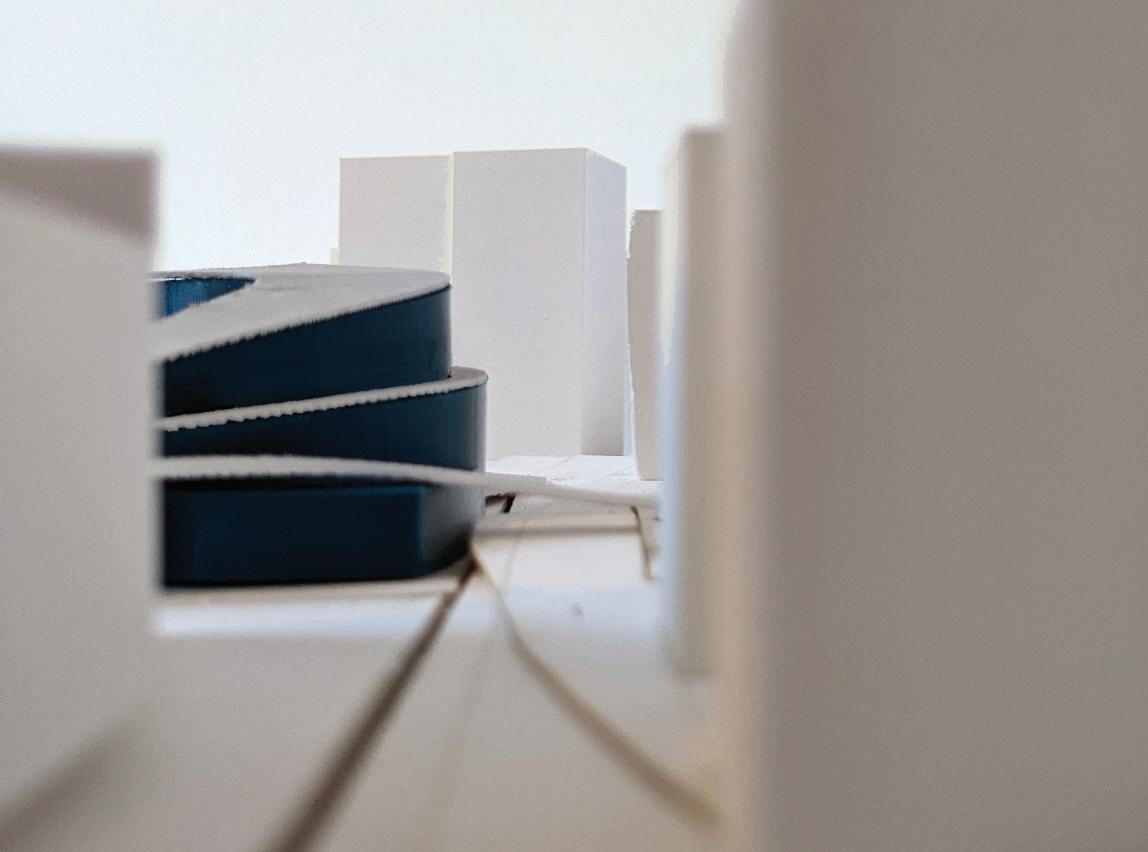
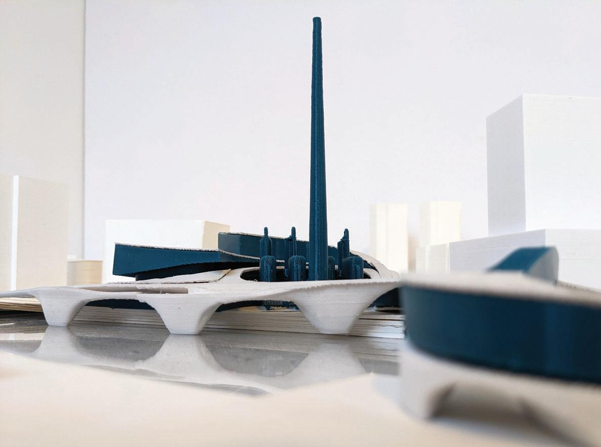
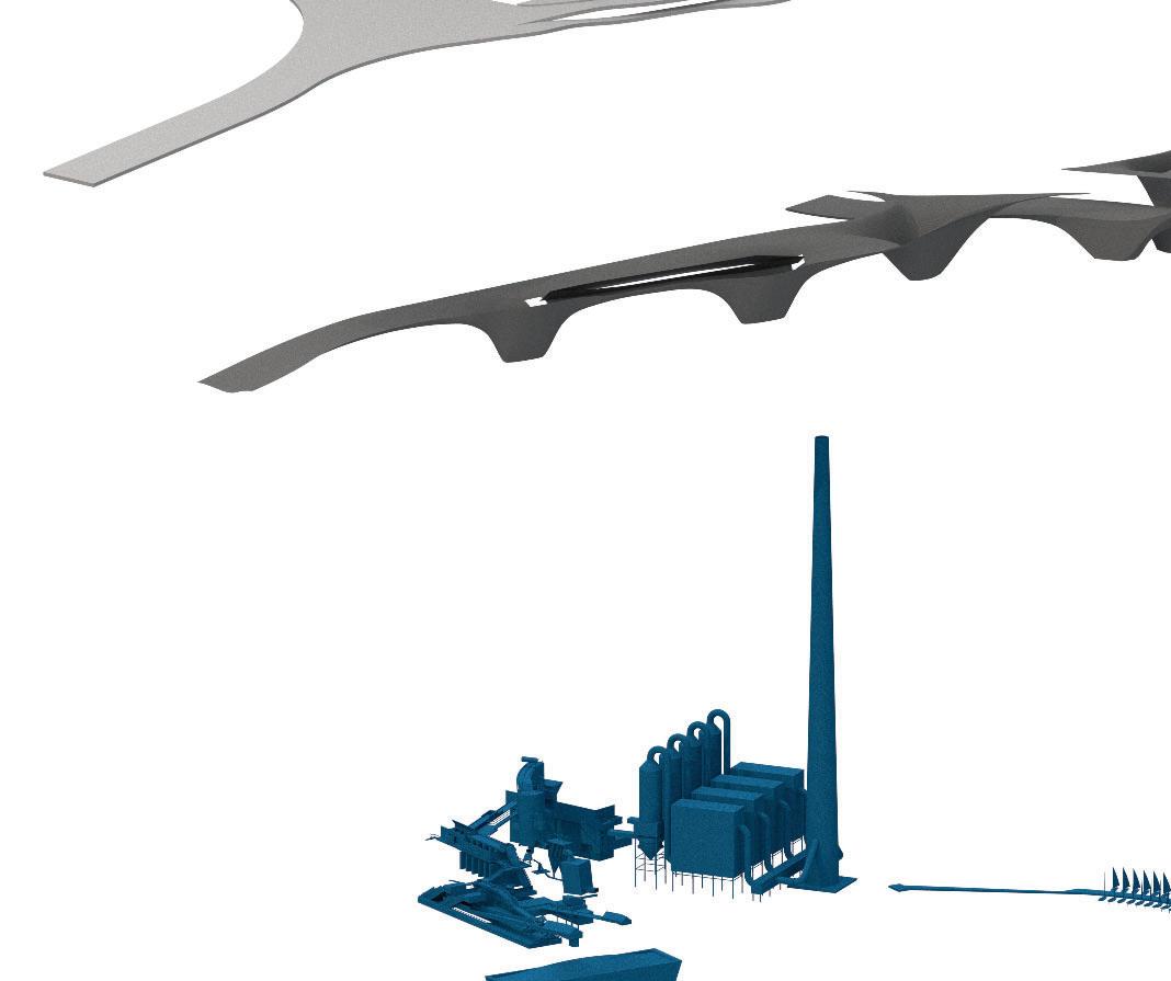
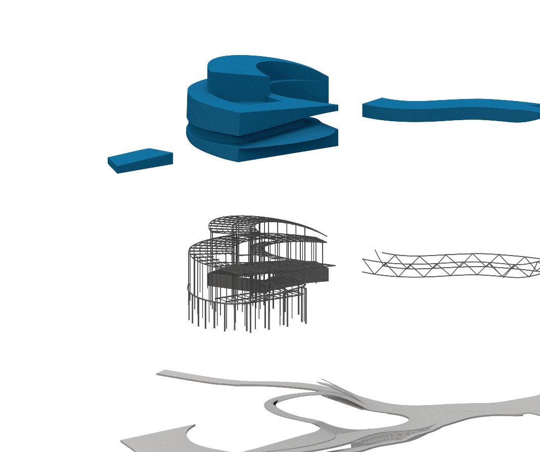
A LOCAL VORTEX
Collaboration: Venice Patron
Brooklyn’s waterfront is in the midst of a century long transition from industrial to residential and commercial use. Broadly precipitated by the closing of the Brooklyn Navy Yard in the 1966, the Navy Yard has now transitioned to contemporary industrial/commercial development following decades of underuse. Our proposal situates itself in this temporal continuum in a new combination - a waste-to-energy plant, recycling center and public sailing facility weaved by a parkscape. Neighboring conditions and differing local social groups leads to a new, intentional design which utilizes a transitional park space to reach out and into the surrounding context while strategically organizing various means of circulation.
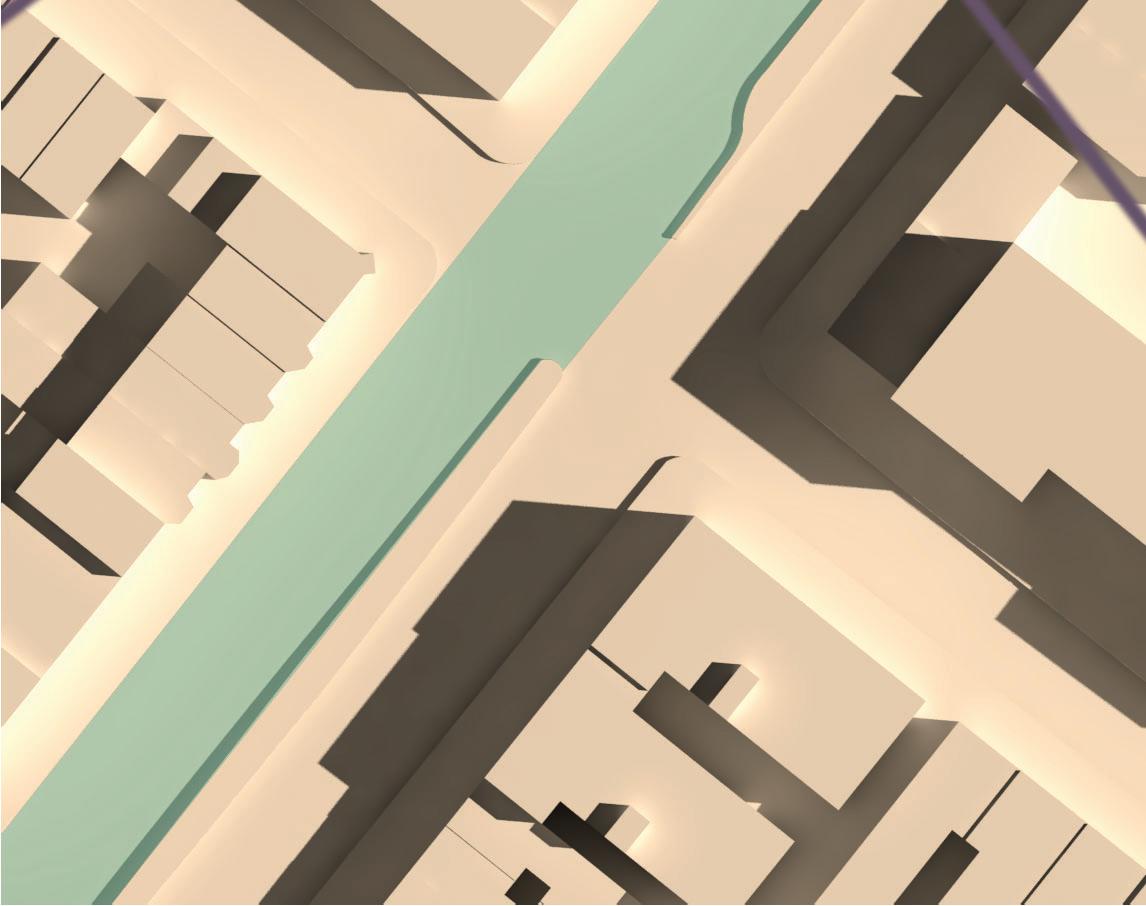
opposite: detailed chunk model above: channel interaction

 JAMES SLADE
detailed chunk model
context model
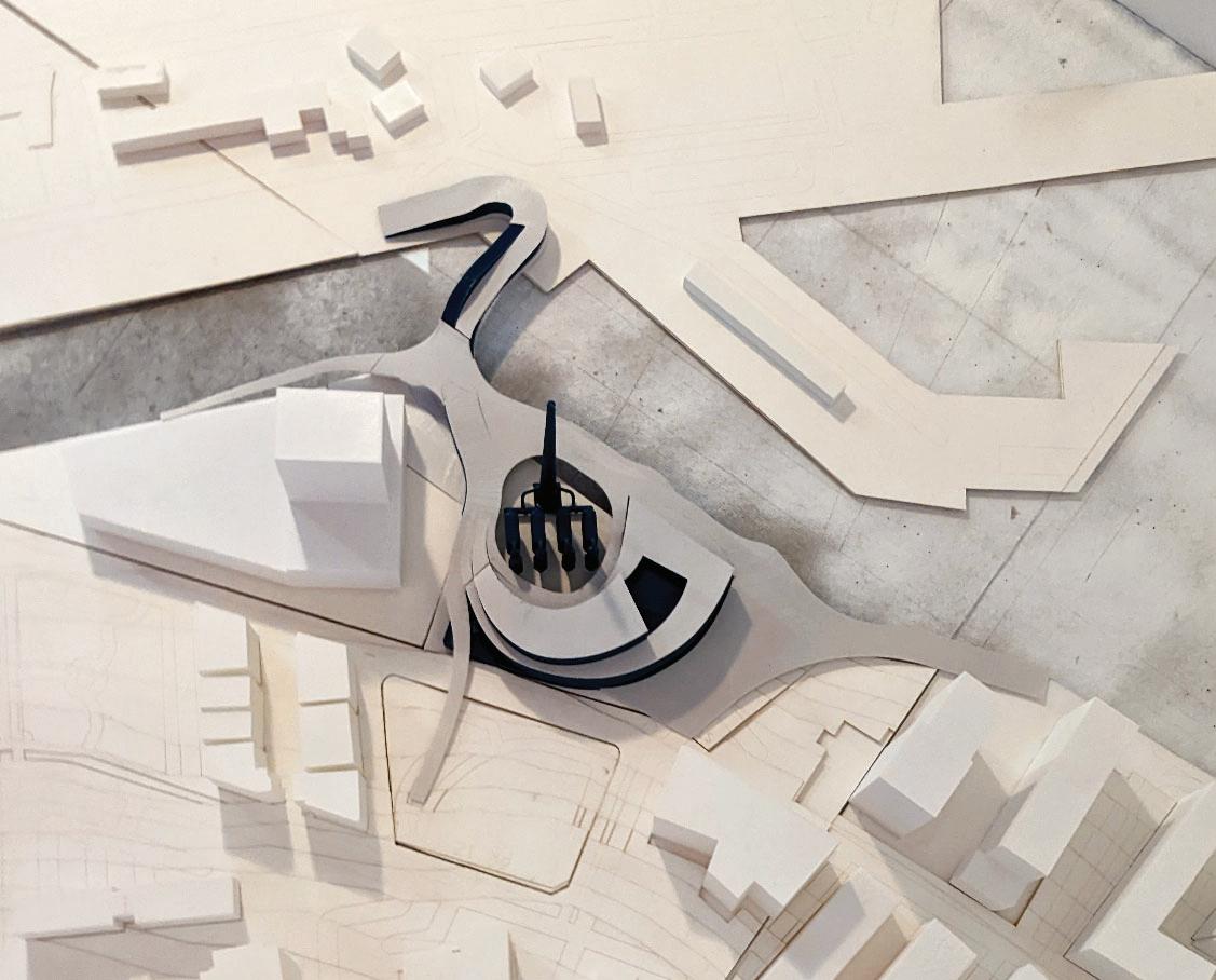
ground floor and park floor plans
waterfront continuity kent ave rampscape bbq overlook grassy hill lofted bar incinerator waste sorting park bridge park rooftop ramp hike rooftop ramp amphitheater playground sailing school balcony brooklyn navy yard 1 2 3 4 5 6 7 8 9 10 11 12 13 14 10 12 13 14 11 1 1 2 3 4 5 6 7 9 8 werc administration recycling sorting tipping hall waste holding area exhaust treatment cafe restaurant lobby classroom living shoreline marina lecture hall 1 2 4 5 6 9 10 11 8 7 8 8 3 1 2 3 4 5 6 7 8 9 10 11
perspective renders and structural axon


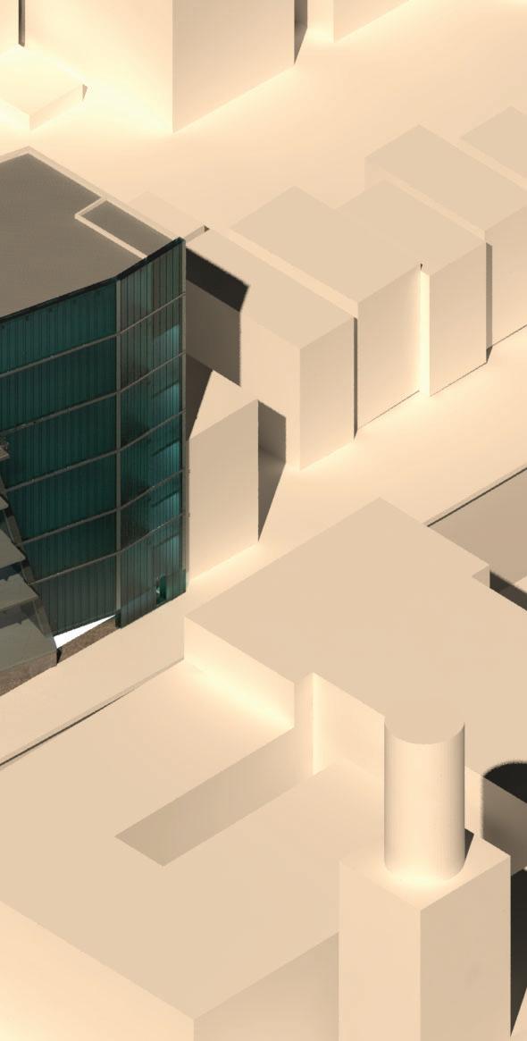
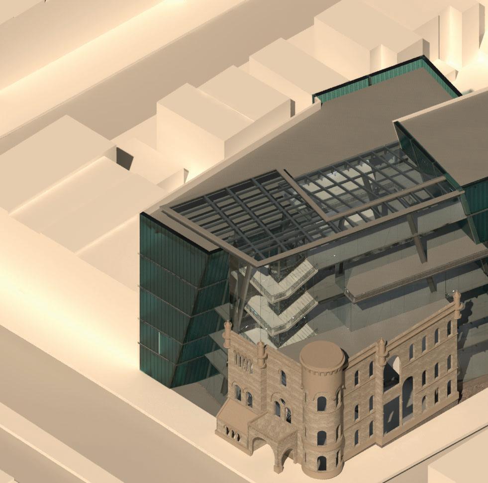
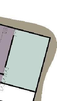
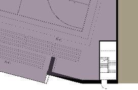
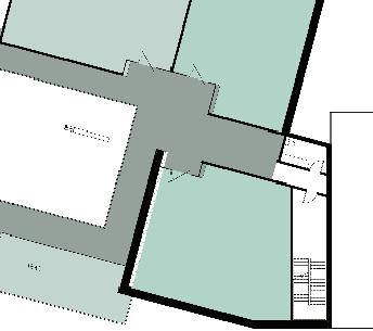
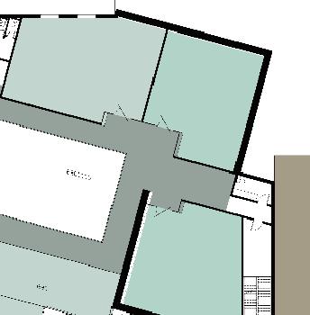
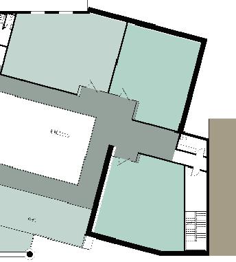
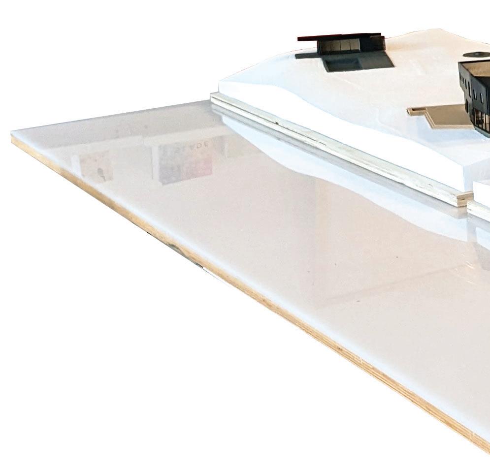
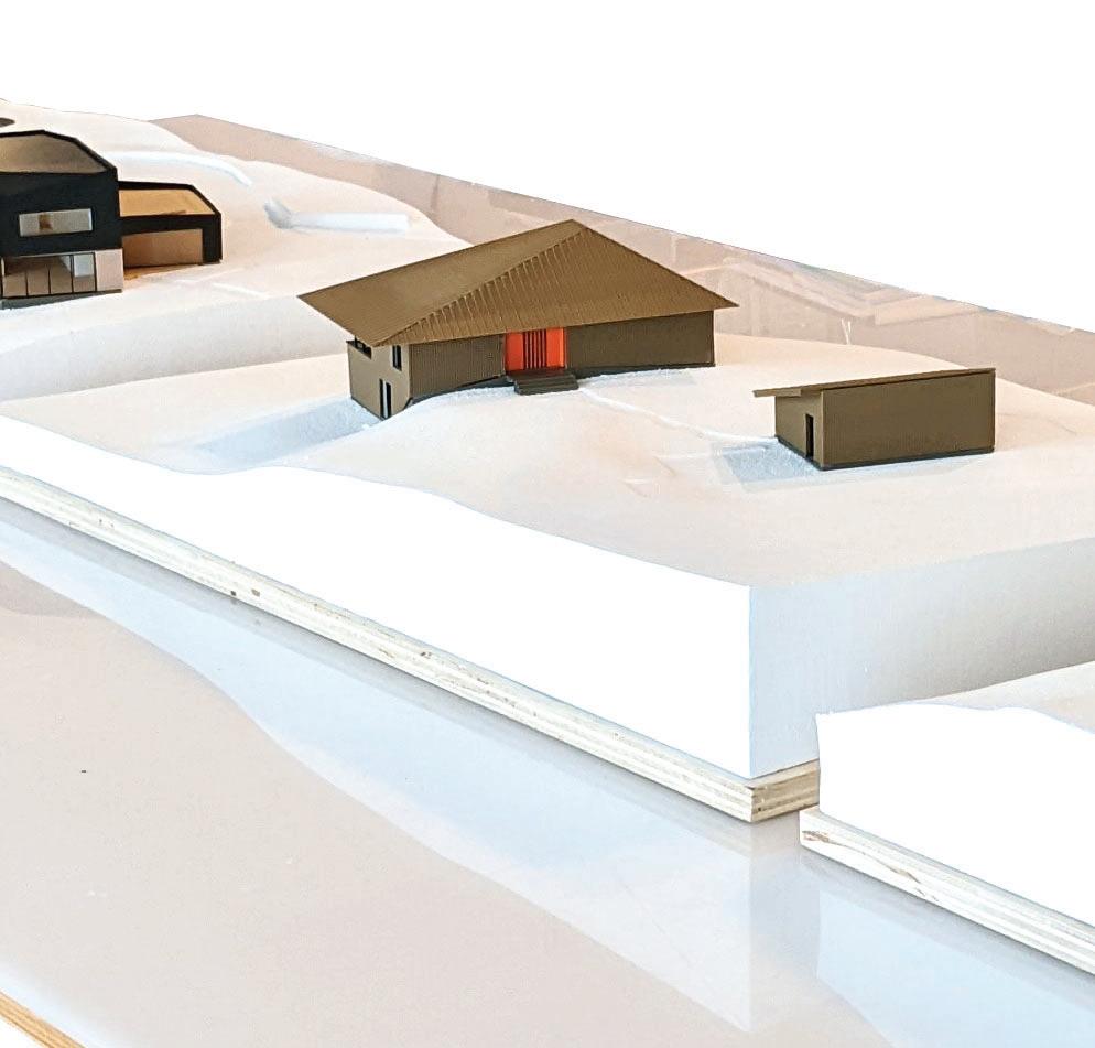
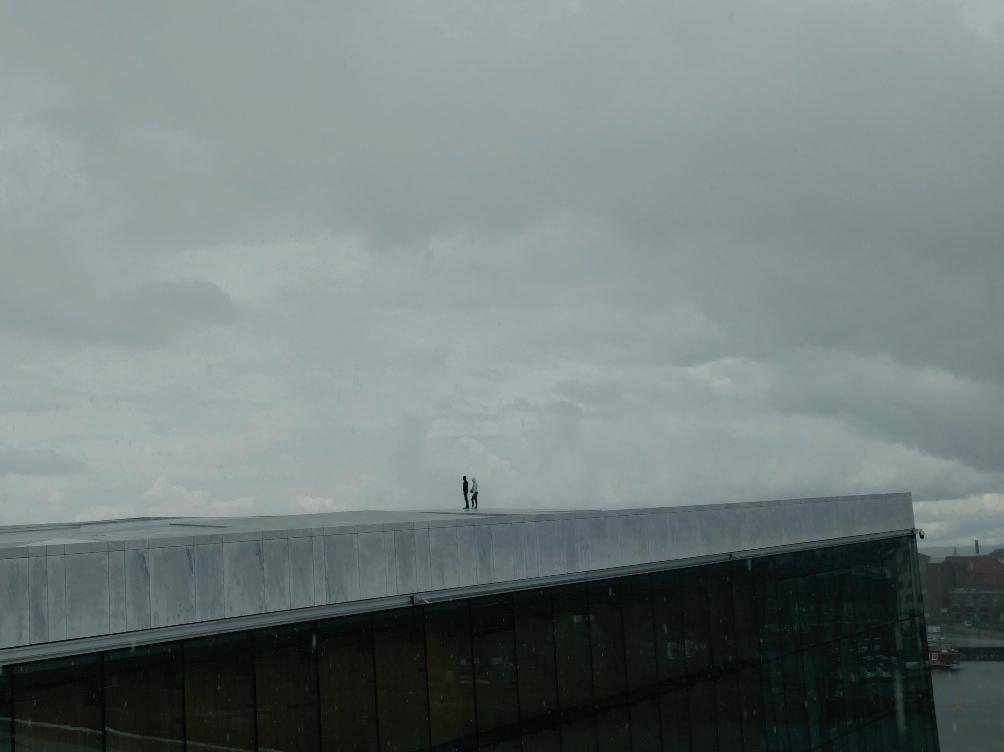
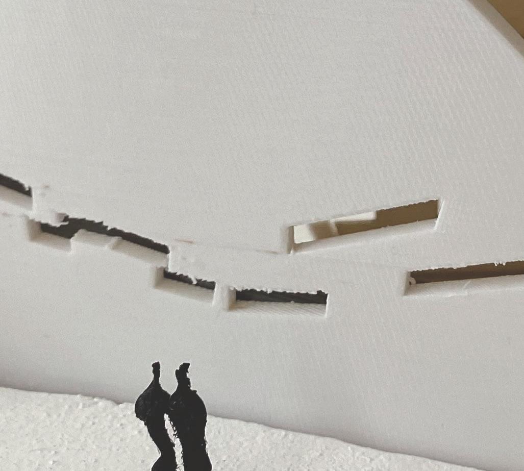
SHIFTING CONTEXTS

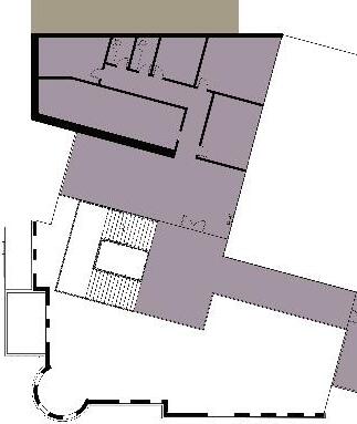
Turning within its context, this middle school sits in dialogue with its neighborhood and existing elements. Located in Sunset Park, Brooklyn, the historic facade of a landmark police station is reconstituted as a departure point for a new use and a new language. Imagined as a community center and a secure home for young neighbors, two atriums anchor a vertically split program that houses public-facing activities near street lev el and e levates the educational facilities into the light. A slight rotation of the interior organization serves a split purpose. Disconnecting the school from the police station to remaining as a platform for continued recontextualization. Drawing from Barcelona’s Eixample, the rotation takes advantage of Sunset Park’s existing urban tilt to provide direct light on all sides of the building throughout the year.

 JAMES GARRISON
opposite: architectural and urban grids above: in context
JAMES GARRISON
opposite: architectural and urban grids above: in context


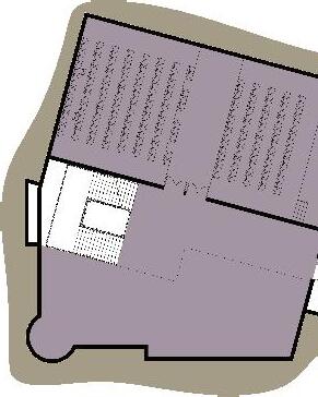

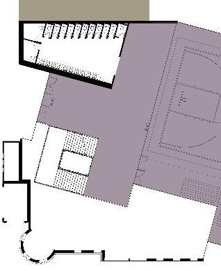
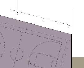

lower floors engage community lower lobby auditorium music room custodial main lobby gymnasium outdoor garden administration principal assistant principal pto office nurse psychologist faculty lounge conference restroom 1 2 3 4 5 6 7 8 9 10 11 12 13 14 15 16 1 2 3 4 5 6 14 7 8 9 10 11 12 13 14 15 16
upper floors focus on students

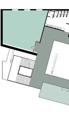

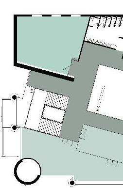
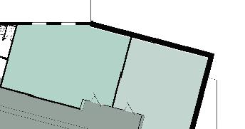
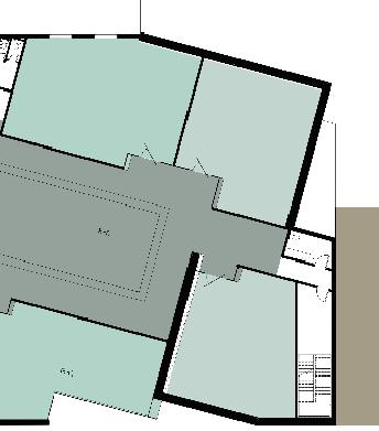
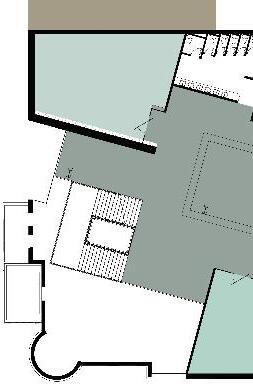


restroom indoor garden classroom art room science room library outdoor study special topic cafeteria outdoor play 16 17 18 19 20 21 22 23 24 25 16 16 16 17 18 18 18 18 18 18 19 20 23 23 21 22 22 18 18 18 24 25


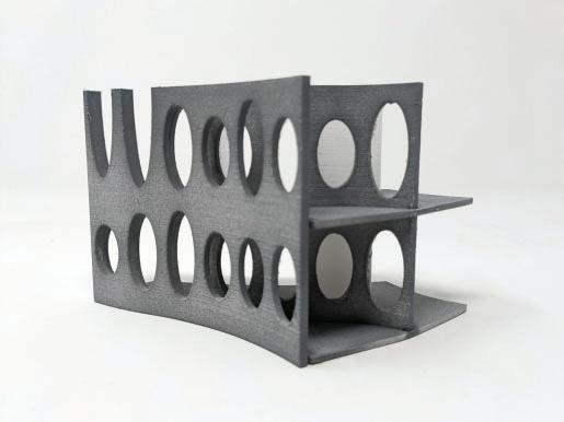
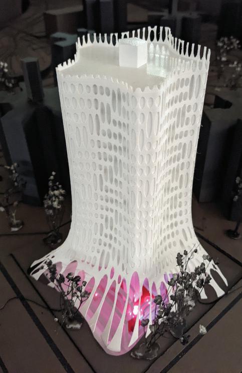
BOOLKLYN TOWER
Collaboration: Audrey Tuck
Sited on within NYC Housing Authority’s Farragut Houses, multifamily Boolklyn tower takes its organization from the existing pentagonal towers and softened. Oval openings were parametrically generated to allow each apartment to enjoy a double height living space. This perforated skin was drawn outward to form a second skin, allowing the building to recede and return to view and creating outdoor spaces for apartments. The ground floor provides food and employment for the campus’ residents in the form of a vertical farm, restaurant, and produce market. At grade, the skins pull apart once again, forming a colonnade circulation the Farragut-facing sides. This intermediate area provides space for markets and programming.
opposite: perspective
above: bird’s-eye
right: contextual collage
 STEPHANIE BAYARD

sunken farming farmers market resident lounge reception / mail restroom farm to table cafe bar porch one bedroom two bedroom three bedroom 1 2 3 4 5 6 7 8 9 10 11 1 1 1 2 3 4 11 11 10 10 9 10 5 5 6 7 8 1 1
ground and typical floor plans
model views
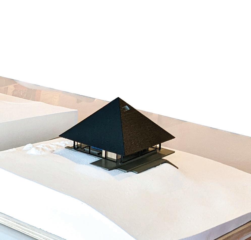


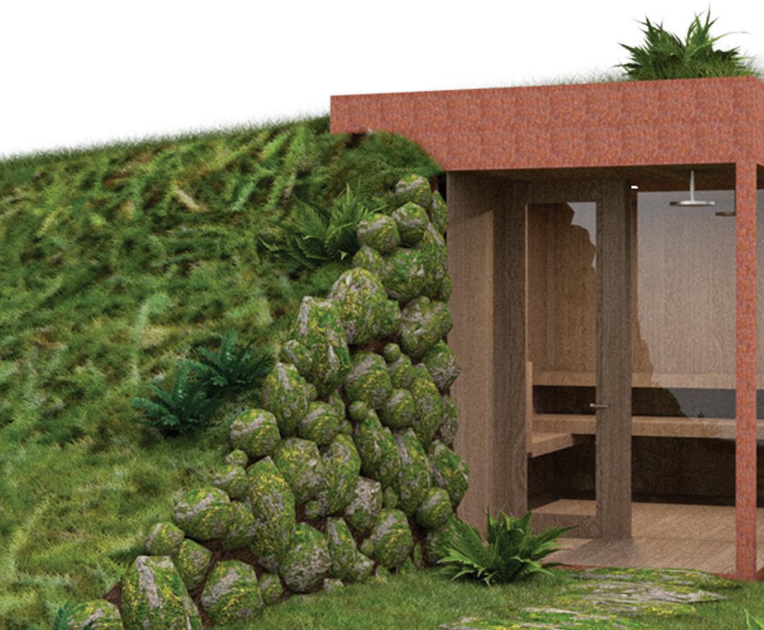
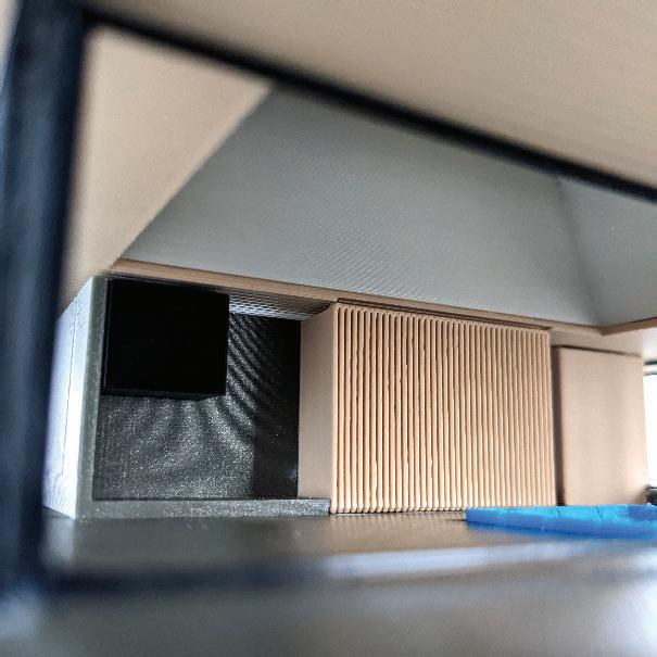
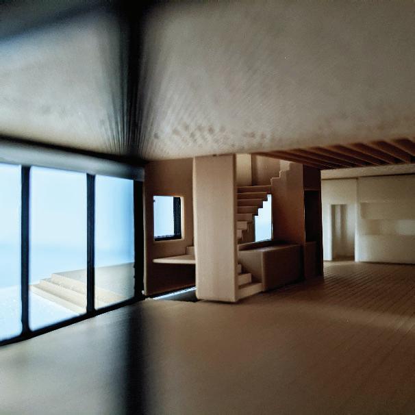
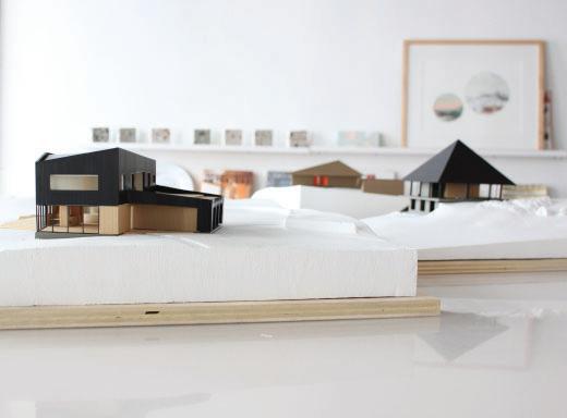
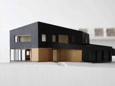
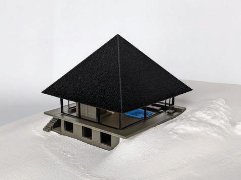
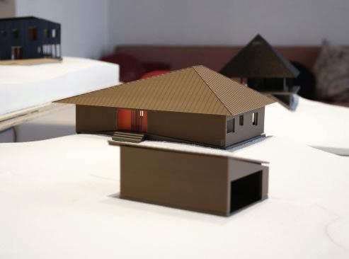
SLADE ARCHITECTURE


Diverse projects required varied skills through this summer internship as part of a small, dynamic team. The most significant work was the modeling and fabrication of five distinct physical models for three residential projects in the firm’s recent portfolio. These models required the optimization and occasional reconfiguration of existing design for successful 3D printing -which was the desired method. These models consisted of 85 separate prints representing materiality, finishes and furnishing which were then integrated with CNC milled bases. The models were also designed to allow disassembly for exhibition. Other highlights include a single-day charette style design and proposition of a sunken cor-ten and cedar sauna, intricate detailing of a bespoke bar and staircase, and signage design for a flagship retail store.
 HAYES SLADE JAMES SLADE
GARRISON ARCHITECTS
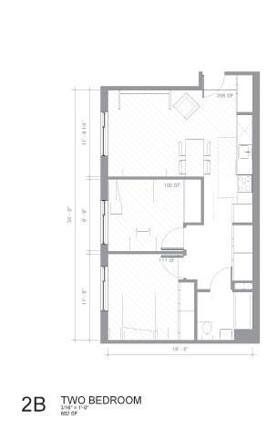
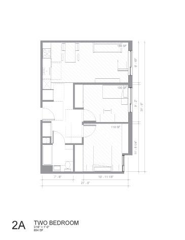
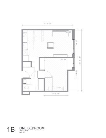
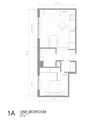
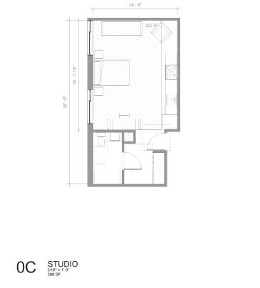
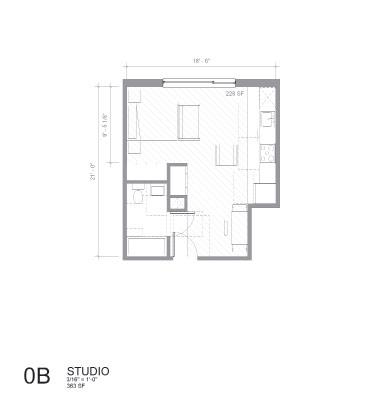
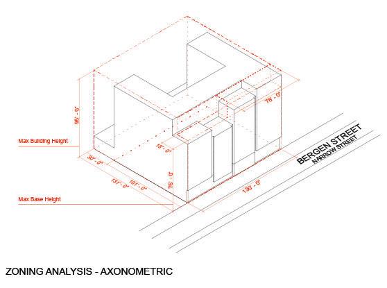
This proposal for affordable housing in Brooklyn’s gentrifying Prospect Heights neighborhood was completed in a taut three week process from initial sketches to submission. The team worked under the direct guidance of firm founder James Garrison, in conjunction with local non-profit developer Spatial Equity Co for this design competition held by NYC Housing Preservation & Development (HPD). My role focused initially on neighborhood research and zoning calculations, before centering on apartment layout design. Extremely efficient apartment layouts were laid out according to rigorous HPD design guidelines repeatedly iterated upon. Lifestyle considerations in daylighting, internal circulation, and universal ADA accessibility played against modularity and other cost-saving measures.
JAMES GARRISON
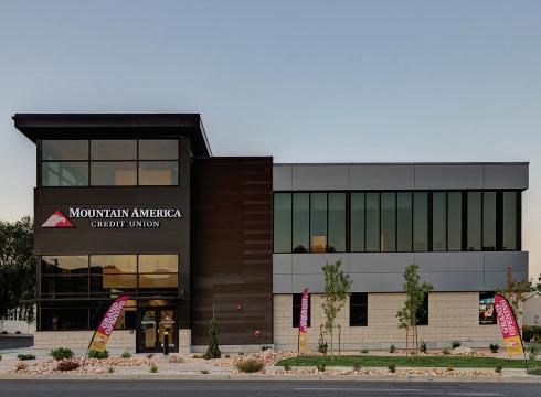
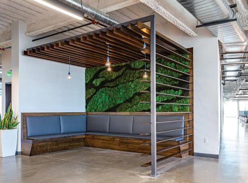
BABCOCK DESIGN
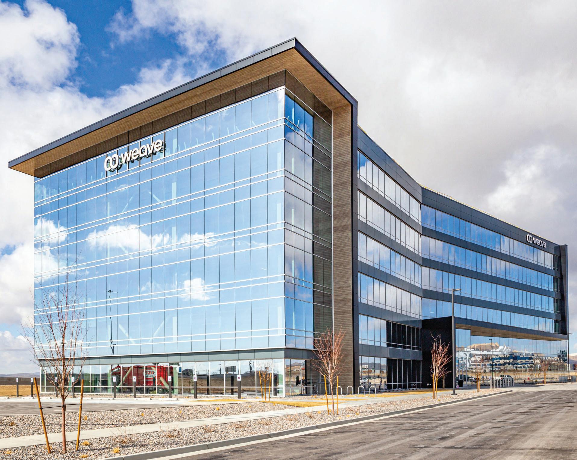
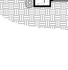
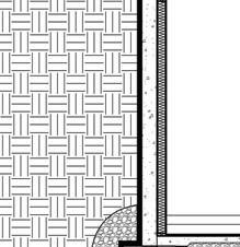
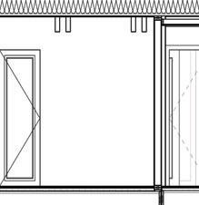
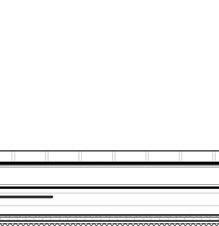
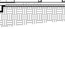
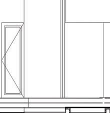
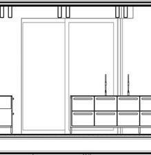
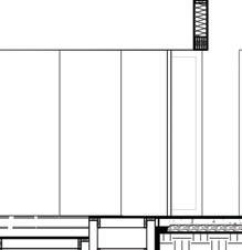
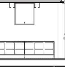
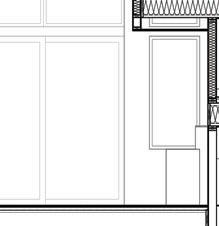
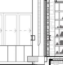
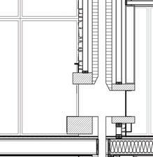
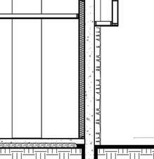
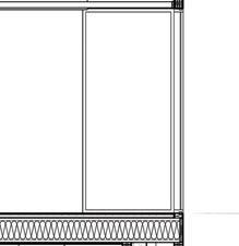
Situated in Babcock Design’s commercial and industrial architecture studio, I aided in the design, documentation, and construction administration of more than twenty projects. I engaged with projects ranging in scale and complexity from neighborhood banks to million-square foot shipping and logistics warehouses. Within these, I was given design leadership over particular aspects of these projects, two of which are seen here: a modular office collaboration hub and an intermediary logistics space within a shipping regional center. Both of these sub-projects required collaborating and coordinating with larger design teams, contractors, and owners. The work regularly required precise references to specification and well-developed schedules and details, all held to a high standard of accuracy internally and externally.
--6-------(WHERE OCCURS) Boise Salt Lake City 52 Exchange Place project information: THE CONTRACT DOCUMENTS, REVIEW ALL DRAWINGS AND REQUIRED NOT FOUND, NOTIFY ARCHITECT IMMEDIATELY FOR OTHER REQUIREMENTS OF THE AUTHORITY HAVING JURISDICTION 19. COORDINATE WITH ELECTRICAL DRAWINGS FOR POWER, DATA, AND 9 10 11 MASTER -FLOATING HUDDLE COLLABORATION -PLAN 2 MASTER -FLOATING HUDDLE COLLABORATION -RCP HUDDLE COLLABORATION FRONT ELEVATION HUDDLE COLLABORATION BACK ELEVATION 5 HUDDLE COLLABORATION ELEVATION HUDDLE COLLABORATION ELEVATION 7 HUDDLE COLLABORATION ELEVATION 12 13 14
LARRY OLDHAM


A110 3 A110 A110 18 S T R 19.9 11' 3" 1 2 A 3 5 A110 VESTIBULE 100 6 8 26' 2 7/8" 13 13 14 17 A111 A111 102 101 5' 0 1/2" 27 VESTIBULE GENERAL NOTES: 1. DRAWINGS & SPECIFICATIONS ARE COMPLIMENTARY COMPONENTS OF THE CONTRACT DOCUMENTS, REVIEW ALL DRAWINGS AND SPECIFICATIONS FOR THE COMPLETE SCOPE OF WORK. NOTIFY ARCHITECT IMMEDIATELY FOR CLARIFICATION IF INCONSISTENCIES, CONTRADICTIONS OR OMISSIONS ARE DISCOVERED. 2. DO NOT SCALE DRAWINGS, IF DIMENSIONAL INFORMATION IS REQUIRED & NOT FOUND, NOTIFY ARCHITECT IMMEDIATELY FOR CLARIFICATION BEFORE PROCEEDING WITH CONSTRUCTION. 3. ALL DIMENSIONS ARE TO COLUMN CENTERLINES, TO GRIDLINES OR TO FACE OF FRAMING UNLESS NOTED OTHERWISE. 4. UNLESS NOTED OTHERWISE CLEAR DIMENSIONS INDICATE DIMENSION BETWEEN FINISHES. 5. CONTRACTOR SHALL NOTIFY THE ARCHITECT OF DISCREPANCIES IN THE DOCUMENTS, AND OF ANY FIELD CONDITIONS THAT DEVIATE FROM THE DOCUMENTS. 6. THE ARCHITECT'S APPROVAL MUST BE OBTAINED FOR ANY DEVIATIONS FROM THE CONSTRUCTION DOCUMENTS, INCLUDING BUT NOT LIMITED TO CHANGES IN DIMENSIONS, DESIGN, MATERIALS, PRODUCTS, AND FINISHES. IN NO CASE MAY THE CONTRACTOR MAKE THESE CHANGES WITHOUT THE APPROVAL OF THE ARCHITECT. 7. SHOP DRAWINGS AND OTHER SUBMITTALS ARE TO BE PRESENTED TO THE ARCHITECT FOR REVIEW PRIOR TO EXECUTION OF WORK. ALLOW APPROPRIATE TIME FOR REVIEW. 8. SEE DOOR SCHEDULE FOR SIZES, TYPES, AND FINISHES, HARDWARE, ETC. 9. FOR BUILDING CODE REQUIREMENTS OR FIRE/SMOKE REQUIREMENTS, SEE 'G' SHEETS. 10. ALL FIRE RATED WALLS TO BE LABELED AS FIRE RATED. LABEL TO BE PLACED ABOVE CEILING LINE. 11. SEE WALL TYPE CONSTRUCTION DETAILS ON SHEETS A111 FOR WALL TERMINATIONS, ETC. 12. HINGE SIDE OF DOORS ARE LOCATED 4" FROM ADJACENT WALL UNLESS NOTED OTHERWISE. 13. ANY COLUMN FURRING TO BE TIGHT TO COLUMN UNO. 14. ALL CONSTRUCTION SHALL CONFORM TO AND STRICTLY COMPLY WITH ALL APPLICABLE CODES, COVENANTS, RESTRICTIONS, AND OTHER REQUIREMENTS OF THE AUTHORITY HAVING JURISDICTION OVER THE PROJECT. 15. IN NO EVENT SHALL THE CONTRACTOR SUBMIT A STANDARD CONSTRUCTION DETAIL FOR A DETAIL SPECIFIED IN THESE DOCUMENTS WITHOUT THE APPROVAL IN WRITING FROM THE ARCHITECT. THE CONTRACTOR SHALL BRING ALL WORK INTO CONFORMITY WITH THE CONSTRUCTION DOCUMENTS, AS THE ARCHITECT ORDERS, BEFORE APPROVAL OF THAT PORTION OF THE PROJECT WILL BE GRANTED. 16. BRACE ALL CEILINGS AND NON-LOAD BEARING WALLS AS REQUIRED. 17. CONTRACTOR TO COORDINATE ALL FLOOR PENETRATIONS WITH ALL TRADES. ALL PENETRATIONS ARE TO BE 2-HOUR FIRE STOPPED. 18. COORDINATE WITH ELECTRICAL DRAWINGS FOR POWER, DATA, AND OTHER SYSTEM LOCATIONS AND REQUIREMENTS. 19. THE FURNITURE AND OTHER F.F.E. SHOWN ON DRAWINGS IS SCHEMATIC AND IS ONLY TO BE USED FOR REFERENCE ONLY. THE CONTRACTOR SHALL COORDINATE THE FINAL LOCATION OF ELECTRICAL OUTLETS AND OTHER NEEDS WITH THE OWNER AND ARCHITECT, PRIOR TO INSTALLATION. 20. MATCH LIGHTING TO EXISTING LIGHTING 21. REFER TO SPECIFICATION SECTION "092116 GYPSUM BOARD ASSEMBLIES" FOR WALL ASSEMBLY INFORMATION 22. STOREFRONT GLAZING MATERIAL TYPES: GL-4: 1/4" CLEAR GLASS, GL-4T: 1/4" TEMPERED CLEAR GLASS 23. MATCH CUBBY STRUCTURE AND SPACING TO EXISTING CUBBY 24. REQUIRED MEANS OF EGRESS AND FIRE PROTECTION SYSTEMS SHALL BE MAINTAINED DURING CONSTRUCTION AND DEMOLITION, REMODELING OR ALTERATIONS AND ADDITIONS TO THE BUILDING. FIRE PREVENTION BUREAU STAFF SHALL APPROVE REVIEW OF ANY EXITING ALTERATIONS. AS REQUIRED IN IFC SECTION 3311.2 25. AUTOMATIC FIRE SPRINKLER, FIRE SUPPRESSION, AND FIRE ALARM SYSTEMS WHEN TAKEN OUT OF SERVICE ARE REQUIRED TO HAVE THE FIRE PREVENTION BUREAU NOTIFIED AT (801) 799-4150. THE DURATION OF TIME AND TEH DATE MUST BE STATED TO INCLUDE DATE WHICH THE FIRE PROTECTION EQUIPMENT WILL BE PLACED IN SERVICE. AS REQUIRED IN IFC CHAPTER 33. 26. ALL FIRE PROTECTION AND DETECTION SYSTEMS SHALL HAVE THE PIPING AND WIRING EXPOSED FOR INSPECTION. THE PIPING AND WIRING MAY BE COVERED AFTER THE FIRE INSPECTION OF TEH SYSTEMS HAS SUCCESSFULLY PASSED REQUIRED INSPECTIONS. LEVEL 100' - 0" LEVEL 112' - 0" 18 2" 3' 1/8" 2" 6' 9" 2" 4 7/8" GL-4T GL-4T GL-4T GL-4 GL-4 GL-4 GL-4T 1' 3" 6' 5" 2'2" 1' 1" 18 26 102 A111 13 A111 10 A111 11 A111 12 A111 14 A111 1 LEVEL 1 100' - 0" LEVEL 2 112' - 0" S A110 26' 1/8" 18 18 26 1 LEVEL 100' - 0" LEVEL 112' - 0" 18 GL-4T GL-4 GL-4T GL-4 GL-4T GL-4 GL-4T 1' 1" 2" 2'2" 6' 7" 2" 1' 5" 7/8" 3' 2" 2" 3' 7" 2" 3' 7 1/8" 2" 18 26 101 13 A111 10 A111 11 A111 12 A111 A111 14 A111 1 LEVEL 1 100' - 0" LEVEL 2 112' - 0" 18 METAL STUD FRAMING - REFER TO UPSPEC 092116 "GYPSUM BOARD ASSEMBLIES" GYPSUM BOARD - REFER TO UPSPEC 092116 "GYPSUM BOARD ASSEMBLIES"12" COUNTER W/ CUBBIES BELOW EXISTING GLAZING EXISTING WALL ASSEMBLY VESTIBULE 100 EXISTING STUD FRAMING TO REMAIN SISTER STUDS TO EXISTING STUDS - SEE STRUCTURAL 2'x4' ACOUSTIC TILE CEILING - REFER TO UPSPEC 095100 "ACOUSTICAL CEILINGS" 6" METAL STUD WALL-MOUNTED PTAC UNIT - MOUNT MIN. 7'-0" AFF - COORDINATE WITH MECHANICAL REROUTE EXISTING FIRE SUPPRESSION SYSTEM THROUGH UTILITY SPACE AND PROVIDE SUFFICIENT FIRE SUPPRESSION WITHIN VESTIBULE. COORDINATE WITH MECHANICAL 7' 0" MIN. SOUNDPROOF ACOUSTIC BATT BETWEEN METAL STUD FRAMING - REFER TO UPSPEC 092116 "GYPSUM BOARD ASSEMBLIES" 1/2" 362S162-33 AT 16" O.C. 600S162-43 AT 24" O.C. 26 GA SHALLOW VERCOR METAL DECK. FASTEN TO CEILING JOISTS WITH #12 O.C. (4 FASTENERS PER 36" WIDE SHEET) AND 12" O.C. TO SUPPORTS PARALLEL TO DECK CORRUGATIONS. CONNECT SIDELAPS WITH #10 STS AT 12" O.C. SIMPSON L50 CLIP AT EACH JOIST WITH (3) #10 STS TO JOIST AND (3) 3/16" P.A.F. TO CHANNEL (E)MC12 CHANNEL (E) 3 1/2" TOTAL CONCRETE OVER METAL DECK INDIRECT CONDENSATE LINE TO OWNER-PROVIDED STORAGE CONTAINER. CONTAINER TO BE EMPTIED PER OWNER MAINTENANCE SCHEDULE A110 3 A110 A110 18 S T 19.9 A110 ACT-2 10' 6" 15 16 EXNEW N35 IN 18 18 11 25' 6 3/8" L1E D 20 20 21 21 22 23 L1E L1 L1E H3A-25 24 25 H3A Boise 800 W MAIN STREET SUITE 940 BOISE, ID 83702 208.424.7675 Salt Lake City 52 Exchange Place Salt Lake City, UT 84111 801.531.1144 6424070 HNO N WI SE W A GE CENS D RCHI E L A TECT STATE OF UTAH sheet number: sheet title: stamp: The information and content represented herein considered law the architect's instruments of service and are the property Babcock Design. They are available for limited reviewand evaluation clients, consultants, contractors, government agencies, vendors, and office personnel only accordance with this notice. They are intended for use only for the project specified and are be used for no other purpose or No part thereof may copied, reproduced, photographed, modified, published, uploaded, transmitted, disclosed, sold, distributed to others written consent of Babcock Design. revisions: date: COPYRIGHT© 2019 BABCOCK DESIGN original drawing 30" 42" for: sheet information: project information: babcockdesign.com project number: project status: current of: stamp: 3/19/2021 11:49:49 AM UPS REGIONAL HUB COMPLEX "H" VEST IBULE VEST IBULE D RAWINGS A110 380 SOUT H 6400 WEST SALT LAKE CIT Y, UT 84104 20098 UPS 1/8" 1'-0" 1 LEVEL 1 FLOOR PLAN NOTE: THESE NOTES APPLY TO THIS SHEET ONLY. SHEET NOTES METAL STUD FRAMING REFER TO UPSPEC 092116 "GYPSUM BOARD ASSEMBLIES" GYPSUM BOARD REFER TO UPSPEC 092116 "GYPSUM BOARD ASSEMBLIES" 24" COUNTER W/ CUBBIES BELOW 12" COUNTER 12" COUNTER W/ CUBBIES BELOW EXISTING WALL ASSEMBLY 7 EXISTING DOOR 8 EXISTING GLAZING EXISTING STUD FRAMING TO REMAIN 10 SISTER STUDS TO EXISTING STUDS SEE STRUCTURAL 11 2'x4' ACOUSTIC TILE CEILING REFER TO UPSPEC 095100 "ACOUSTICAL CEILINGS" 12 6" METAL STUD 13 GLAZING SYSTEM AS SCHEDULED 14 WALKWAY ABOVE 15 RELOCATED EXISTING LIGHT FIXTURE 16 EXISTING LIGHT FIXTURE TO REMAIN, PROTECT IN PLACE 17WALL-MOUNTED PTAC UNIT MOUNT MIN. 7'-0" AFF COORDINATE WITH MECHANICAL 18 REROUTE EXISTING FIRE SUPPRESSION SYSTEM THROUGH UTILITY SPACE AND PROVIDE SUFFICIENT FIRE SUPPRESSION WITHIN VESTIBULE. COORDINATE WITH MECHANICAL 19SOUNDPROOF ACOUSTIC BATT BETWEEN METAL STUD FRAMING REFER TO UPSPEC 092116 "GYPSUM BOARD ASSEMBLIES" 20CONNECT EXIT SIGN TO UNSWITCHED LEG OF CIRCUIT H3A-25 21 REMOVE AND SALVAGE EXISTING LIGHT FIXTURE 22PROVIDE NEW 30 CANDELA HORN/STROBE NOTIFICATION DEVICE. EXTEND CIRCUIT FROM EXISTING 75 CANDELA HORN/STROBE DEVICE IN ADJACENT OFFICE. ALSO RELOCATE EOL RESISTOR FROM EXISTING 75 CANDELA HORN/STROBE AND MOVE TO NEW 30 CANDELA HORN/STROBE DEVICE. 23 PROVIDE 20A/1P, 277V, SINGLE-PHASE EQUIPMENT CONNECTION FOR PTAC-1 MECHANICAL EQUIPMENT. COORDINATE EXACT LOCATION WITH MECHANICAL PRIOR TO ROUGH-IN 24EXTEND EXISTING CIRCUIT TO NEW L1 FIXTURES 25 EXISTING 277/480V, 3-PHASE PANELBOARD, "H3A" 26 SIGNS FIXED TO BOTH SIDES OF RAILING TO READ NO STORAGE ALLOWED" 27INDIRECT CONDENSATE LINE TO OWNER-PROVIDED STORAGE CONTAINER. CONTAINER TO BE EMPTIED PER OWNER MAINTENANCE SCHEDULE 1/4" 1'-0" 4 NORTH ELEVATION 1/4" = 1'-0" 3 EAST ELEVATION 1/4" 1'-0" 6 SOUTH ELEVATION 5 {3D} 1/2" 1'-0" 7 Section 1 1/8" 1'-0" 2 REFLECTED CEILING PLAN LEVEL 1 NORTH NORTH num.descriptiondate 1City Review 203/01/2 2City Review 303/19/2 1 2 04/27/21
VESTIBULE GENERAL NOTES: 1. DRAWINGS & SPECIFICATIONS ARE COMPLIMENTARY COMPONENTS OF THE CONTRACT DOCUMENTS, REVIEW ALL DRAWINGS AND SPECIFICATIONS FOR THE COMPLETE SCOPE OF WORK. NOTIFY ARCHITECT IMMEDIATELY FOR CLARIFICATION IF INCONSISTENCIES, CONTRADICTIONS OR OMISSIONS ARE DISCOVERED. 2. DO NOT SCALE DRAWINGS, IF DIMENSIONAL INFORMATION IS REQUIRED & NOT FOUND, NOTIFY ARCHITECT IMMEDIATELY FOR CLARIFICATION BEFORE PROCEEDING WITH CONSTRUCTION. 3. ALL DIMENSIONS ARE TO COLUMN CENTERLINES, TO GRIDLINES OR TO FACE OF FRAMING UNLESS NOTED OTHERWISE. 4. UNLESS NOTED OTHERWISE CLEAR DIMENSIONS INDICATE DIMENSION BETWEEN FINISHES. 5. CONTRACTOR SHALL NOTIFY THE ARCHITECT OF DISCREPANCIES IN THE DOCUMENTS, AND OF ANY FIELD CONDITIONS THAT DEVIATE FROM THE DOCUMENTS. 6. THE ARCHITECT'S APPROVAL MUST BE OBTAINED FOR ANY DEVIATIONS FROM THE CONSTRUCTION DOCUMENTS, INCLUDING BUT NOT LIMITED TO CHANGES IN DIMENSIONS, DESIGN, MATERIALS, PRODUCTS, AND FINISHES. IN NO CASE MAY THE CONTRACTOR MAKE THESE CHANGES WITHOUT THE APPROVAL OF THE ARCHITECT. 7. SHOP DRAWINGS AND OTHER SUBMITTALS ARE TO BE PRESENTED TO THE ARCHITECT FOR REVIEW PRIOR TO EXECUTION OF WORK. ALLOW APPROPRIATE TIME FOR REVIEW. 8. SEE DOOR SCHEDULE FOR SIZES, TYPES, AND FINISHES, HARDWARE, ETC. 9. FOR BUILDING CODE REQUIREMENTS OR FIRE/SMOKE REQUIREMENTS, SEE 'G' SHEETS. 10. ALL FIRE RATED WALLS TO BE LABELED AS FIRE RATED. LABEL TO BE PLACED ABOVE CEILING LINE. 11. SEE WALL TYPE CONSTRUCTION DETAILS ON SHEETS A111 FOR WALL TERMINATIONS, ETC. 12. HINGE SIDE OF DOORS ARE LOCATED 4" FROM ADJACENT WALL UNLESS NOTED OTHERWISE. 13. ANY COLUMN FURRING TO BE TIGHT TO COLUMN UNO. 14. ALL CONSTRUCTION SHALL CONFORM TO AND STRICTLY COMPLY WITH ALL APPLICABLE CODES, COVENANTS, RESTRICTIONS, AND OTHER REQUIREMENTS OF THE AUTHORITY HAVING JURISDICTION OVER THE PROJECT. 15. IN NO EVENT SHALL THE CONTRACTOR SUBMIT A STANDARD CONSTRUCTION DETAIL FOR A DETAIL SPECIFIED IN THESE DOCUMENTS WITHOUT THE APPROVAL IN WRITING FROM THE ARCHITECT. THE CONTRACTOR SHALL BRING ALL WORK INTO CONFORMITY WITH THE CONSTRUCTION DOCUMENTS, AS THE ARCHITECT ORDERS, BEFORE APPROVAL OF THAT PORTION OF THE PROJECT WILL BE GRANTED. 16. BRACE ALL CEILINGS AND NON-LOAD BEARING WALLS AS REQUIRED. 17. CONTRACTOR TO COORDINATE ALL FLOOR PENETRATIONS WITH ALL TRADES. ALL PENETRATIONS ARE TO BE 2-HOUR FIRE STOPPED. 18. COORDINATE WITH ELECTRICAL DRAWINGS FOR POWER, DATA, AND OTHER SYSTEM LOCATIONS AND REQUIREMENTS. 19. THE FURNITURE AND OTHER F.F.E. SHOWN ON DRAWINGS IS SCHEMATIC AND IS ONLY TO BE USED FOR REFERENCE ONLY. THE CONTRACTOR SHALL COORDINATE THE FINAL LOCATION OF ELECTRICAL OUTLETS AND OTHER NEEDS WITH THE OWNER AND ARCHITECT, PRIOR TO INSTALLATION. 20. MATCH LIGHTING TO EXISTING LIGHTING 21. REFER TO SPECIFICATION SECTION "092116 GYPSUM BOARD ASSEMBLIES" FOR WALL ASSEMBLY INFORMATION 22. STOREFRONT GLAZING MATERIAL TYPES: GL-4: 1/4" CLEAR GLASS, GL-4T: 1/4" TEMPERED CLEAR GLASS 23. MATCH CUBBY STRUCTURE AND SPACING TO EXISTING CUBBY 24. REQUIRED MEANS OF EGRESS AND FIRE PROTECTION SYSTEMS SHALL BE MAINTAINED DURING CONSTRUCTION AND DEMOLITION, REMODELING OR ALTERATIONS AND ADDITIONS TO THE BUILDING. FIRE PREVENTION BUREAU STAFF SHALL APPROVE REVIEW OF ANY EXITING ALTERATIONS. AS REQUIRED IN IFC SECTION 3311.2 25. AUTOMATIC FIRE SPRINKLER, FIRE SUPPRESSION, AND FIRE ALARM SYSTEMS WHEN TAKEN OUT OF SERVICE ARE REQUIRED TO HAVE THE FIRE PREVENTION BUREAU NOTIFIED AT (801) 799-4150. THE DURATION OF TIME AND TEH DATE MUST BE STATED TO INCLUDE DATE WHICH THE FIRE PROTECTION EQUIPMENT WILL BE PLACED IN SERVICE. AS REQUIRED IN IFC CHAPTER 33. 26. ALL FIRE PROTECTION AND DETECTION SYSTEMS SHALL HAVE THE PIPING AND WIRING EXPOSED FOR INSPECTION. THE PIPING AND WIRING MAY BE COVERED AFTER THE FIRE INSPECTION OF TEH SYSTEMS HAS SUCCESSFULLY PASSED REQUIRED INSPECTIONS. LEVEL 100' - 0" S A110 1 2 4 2' 10" 2' 10" LEVEL 100' - 0" S A110 6 7' 0" MIN. 10 2 2' 10" 45°MAX 45° MAX 45°MAX. 45° MAX MAIN RUNNER CROSS RUNNER 12 GA. BRACING WIRE WITH MIN. TURNS IN 1/2" @ BOTH ENDS OF WIRE, TYP. 2" MAX. GENERAL NOTE: ACOUSTICAL SUSPENDED CEILINGS TO ALSO BE INSTALLED PER MANUFACTURER'S RECOMMENDATIONS, IBC 2015, AND ASTM C 635 AND ASTM C 636. Suspended Ceiling Seismic Provisions from CISCA 0-2 for Design Class C 1. Each individual fixture and attachments with a combined weight of 56 lbs. or less shall have two No. 12 gauge wire hangers attached at diagonal corners of the fixture. These wires must be slack. Any fixtures and attachments with a combined weight greater that 56 lbs. must be independently supported from the structure. 2. The main runner/cross runner intersections and all grid splices must have an average ultimate test strength of 60 lbs. or more in both tension and compression. The tensile test must allow for a 5° offset of the connection in any direction. 3. The actual average weight of the ceiling system, including grid, panels or tile, light fixtures, and air terminals must be 2.5 psf or less. All other services must be supported independently from the ceiling system. For ceilings that have an average weight greater than 2.5 psf, the ceiling may be installed as specified in CISCA Zone 3-4 provisions, taking into account the design lateral force factor appropriate for Zone 2. Other deviations or variations must be substantiated by verifiable engineering data. 4. The ceiling system cannot be used to provide lateral support for walls or partitions. Walls or partitions may be attached to the ceiling grid provided they allow the ceiling membrane to move laterally to accommodate the required clearance as specified below. 5. All perimeter closure angles or channels must provide a support ledge of approximately 7/8 in. or greater. A terminal end of a grid member (or tile) must rest on the ledger or molding with at least 3/8 in. clearance from an edge or wall. 6. For perimeter closure angles that provide a support ledge of less than noted above, the terminal ends of each cross runner or main runner shall be independently supported within 8 in. from each wall or ceiling discontinuity. This support may be a No. 12 gauge hanger wire or other support that prevents the grid from falling. This wire does not need to be vertical but should not have a slope greater than in 6 out- of-plumb. A 3/8 in. grid end clearance from a wall should be maintained. 7. All ceiling penetrations (columns, sprinklers, etc.) and independently supported fixtures or services are to be considered as perimeter closures that also must allow the noted clearances by using suitable escutcheons or closure details. 8. At wall closure ledges, the cross runner and main runner ends shall be prevented from spreading apart from each other. Permanent attachments (i.e. pop rivets) for grid alignment purposed shall not be permitted. 3/4" CONT. SEALANT @ PERIMETER EDGE MOLDING AND WALL (DO NOT PAINT) "BERC2" SEISMIC ACP CEILING GRID CLIP ATTACHED TO PERIMETER EDGE MOLDING ACOUSTICAL CEILING TILE NOTE: DETAIL SHOWS REQUIRED RELIEF EDGE CONDITION. SYSTEM IS SEISMICALLY ATTACHED TO CLIP AND EDGE MOLDING AT FIXED OPPOSITE WALL LOCATIONS 8" MAX SPACEBAR, TO KEEP PERIMETER COMPONENTS FROM SPREADING ACOUSTICAL SUSPENDED CEILING, AS SPECIFIED 3-5/8" MTL. STUD BULKHEAD FRAMING GYPSUM BOARD, PAINT. 3-5/8" MTL. STUD TRACK MIN. ACT CEILING PER RCP 2' 1" 4' 3 1' 0" 4" N4 NARROW VISION TYPICAL FRAME 2" WIDTH 2" 11 3-5/8" METAL STUDS @ 16" O.C. W/ BATT INSULATION IN WALL CAVITY WHERE REQ. SEE WALL TYPES. SHIM AS REQUIRED 5/8" GYPSUM BOARD AT BOTH SIDES PAINTED CONT. BACKER ROD AND SEALANT AT BOTH SIDES J-MOLD AT BOTH SIDES 2" GLAZING SYSTEM AS SCHEDULED 3-5/8" METAL STUDS @ 16" O.C. W/ BATT INSULATION IN WALL CAVITY WHERE REQ. SEE WALL TYPES. CONT. BACKER ROD AND SEALANT AT BOTH SIDES 5/8" GYPSUM BOARD AT BOTH SIDES PAINTED GLAZING SYSTEM AS SCHEDULED SHIM AS REQ. 2" METAL STUDS @ 16" O.C. W/ BATT INSULATION IN WALL CAVITY WHERE REQ. SEE WALL TYPES. CONT. BACKER ROD AND SEALANT AT BOTH SIDES 5/8" GYPSUM BOARD AT BOTH SIDES PAINTED GLAZING SYSTEM AS SCHEDULED SHIM AS REQ. 2" PROVIDE FRAMING/SOLID BLOCKING IN WALL AS REQ. SCHEDULED DOOR, SEE DOOR SCHEDULE 4" CONCRETE SLAB ON GRADE OVER GRAVEL BASE, COORDINAGE WITH STRUCTURAL ALUMINUM THRESHOLD ALUMINUM STOREFRONT SYSTEM RE: PLAN / DOOR WINDOW SCHEDULE 4" CONCRETE SLAB ON GRADE OVER GRAVEL BASE, RE: STRUCTURAL SHIM AS NEEDED SEALANT, BOTH SIDES GLAZING AS SCHEDULED 2" ALUMINUM STOREFRONT DOOR AND FRAME GLAZING AS SCHEDULED 2" 1/2" 4 1/2" GLAZING AS SCHEDULED GLAZING AS SCHEDULED GLAZING AS SCHED. (TYP) ALUMINUM STOREFRONT FRAME ALUMINUM STOREFRONT DOOR AND FRAME GLAZING AS SCHED. (TYP) ALUMINUM STOREFRONT FRAME 4 1/2" 4 1/2" 1/2" 4 1/2" 2" 4 1/2" GWB SOUND AND SMOKE CLOSURE STRIP, SECURED TO STRUCTURE, PROVIDE ON BOTH SIDES AT SOUND WALLS 2"x20 GA STRAPS AT 16" O.C. MTL STUDS METAL DECK (PERPENDICULAR TO FLUTES) METAL DECK (PARALLEL TO FLUTES) MIN. OF ONE LAYER OF GWB CUT TO FOLLOW PROFILE OF DECKING AT SMOKE PARTITION, BOTH AT SOUND WALLS FILL FLUTE VOID W/ SAB 1" 1" 5/8" GYP. BD. SEALANT BOTH SIDES MTL STUDS SLOTTED TOP TRACK 5/8" GYP. BD. SEALANT, BOTH SIDES. REF SPECS FOR TYPE LINE OF STRUCTURE SOUND ATTENUATION BATTS (SAB), WHERE OCCURS METAL STUDS PARTITION WIDTH REF SCHEDULE FOR SEALANT, BOTH SIDES 5/8" GYP. BD. EACH SIDE REF TOP OF WALL CONDITION FOR CONTINUATION AND DETAILS METAL RUNNER Boise 800 W MAIN STREET SUITE 940 BOISE, ID 83702 208.424.7675 Salt Lake City 52 Exchange Place Salt Lake City, UT 84111 801.531.1144 6424070 HNO N WI SE W A GE CENS D RCHI E L A TECT STATE OF UTAH sheet number: sheet title: stamp: The information and content represented herein considered law the architect's instruments of service and are the property Babcock Design. They are available for limited review and evaluation by clients, consultants, contractors, government agencies, vendors, and office personnel only accordance with this notice. They are intended for use only for the project specified and are be used for no other purpose or No part thereof may copied, reproduced, photographed, modified, published, uploaded, transmitted, disclosed, sold, distributed to others in written consent of Babcock Design. revisions: date: COPYRIGHT © 2019 BABCOCK DESIGN original drawing is 30" 42" for: sheet information: project information: babcockdesign.com project number: project status: current of: stamp: 4/5/2021 9:44:52 AM UPS REGION AL HUB COMPLEX "H" VESTIBULE VESTIBULE IN T -ELEVATION S A111 380 SOUTH 6400 WEST SALT LAKE CITY, UT 84104 20098 UPS NOTE: THESE NOTES APPLY TO THIS SHEET ONLY. SHEET NOTES EXISTING GLAZING EXISTING WALL ASSEMBLY EXISTING DOOR 12" COUNTER W/ CUBBIES BELOW 12" COUNTER GYPSUM BOARD REFER TO UPSPEC 092116 "GYPSUM BOARD ASSEMBLIES" 7 WALL-MOUNTED PTAC UNIT MOUNT MIN. 7'-0" AFF COORDINATE WITH MECHANICAL 24" COUNTER W/ CUBBIES BELOW 4" X 4" PAINTED STEEL ANGLE BOLTED TO THE FLOOR MATCH LEADING COUNTER EDGE CANE DETECTABLE BARRIER 10 INDIRECT CONDENSATE LINE TO OWNER-PROVIDED STORAGE CONTAINER. CONTAINER TO BE EMPTIED PER OWNER MAINTENANCE SCHEDULE 1/4" 1'-0" 1 INTERIOR EAST ELEVATION 1/4" = 1'-0" 2 INTERIOR WEST ELEVATION num.descriptiondate 1City Review 203/01/2 2City Review 303/19/2 1'-0" 5 SUSPENDED CEILING SUPPORT STRUCTURE DETAIL 1'-0" 4 TYP. ACT EDGE DETAIL 1'-0" 3 ACT WALL EDGE DETAIL DOOR AND FRAME SCHEDULE IDENTIFICATIONPANEL FRAMEHARDWARE COMMENTS DOOR DOOR # ROOM NAME DIMENSIONS NO. OF PANELS TYPE MATERIAL FINISH GLAZING TYPE MATERIALFINISH FRAME DETAIL HARDWARE SET W H HEADJAMB SILL LEVEL 101 VESTIBULE 3' 0" 8' 0"0' 3/4" 1N4 WOOD-BIRCH LAMINATE GLASS11 ALUMINUM CLEAR ANODIZED ALUMINUM 13/A111 13/A111 9/A11 SEE SPEC101 102 VESTIBULE 3' 0" 8' 0"0' 3/4" 1N4 WOOD-BIRCH LAMINATE GLASS11 ALUMINUM CLEAR ANODIZED ALUMINUM 13/A111 13/A111 9/A11 SEE SPEC102 1/4" 1'-0" 7 SIDE-HINGED DOOR TYPE 1/4" = 1'-0" 8 INSET FRAME TYPE ELEVATION 3" = 1'-0" 9 INTR. ALUM. STOREFRONT HEAD (SILL SIM.) 1'-0" 12 INTR. ALUM. STOREFRONT JAMB @ GYP. BD. 3" = 1'-0" 11 INTR. ALUM. STOREFRONT JAMB @ GYP. BD. 3" 1'-0" 10 ALUM. STOREFRONT DOOR SILL 1'-0" 13 ALUM. STOREFRONT SILL @ CONC. 1'-0" 14 TYP. INTERIOR ALUM. STOREFRONT DETAILS 3" 1'-0" 6 HEAD-OF-WALL DETAILS STUD WALLS - SMOKE PARTITIONS AND SOUND CONTROL WALLS 1 1 1 2 *NOTE: FOR ONE-HOUR RATED WALLS USE UL DESIGN NO. U419; SEE UL RATING SHEET PARTITION TYPE CORE WIDTH PARTITION WIDTH A 0' 3 5/8"0' 7/8" A6 6" 0' 1/4" 3" 1'-0" A METAL STUD WITH 1 LAYER 5/8" GYP. BD. ON EACH SIDE 2 04/27/21
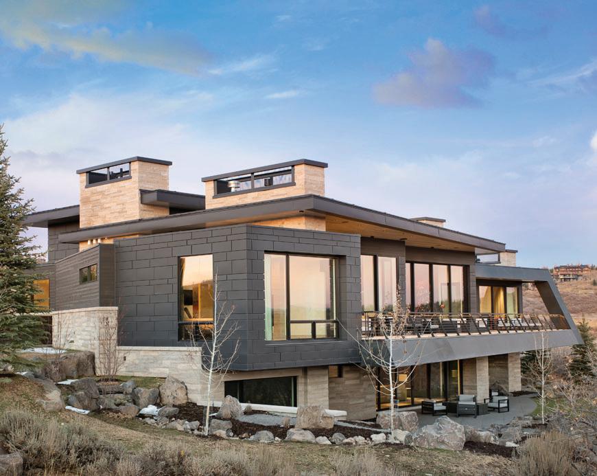
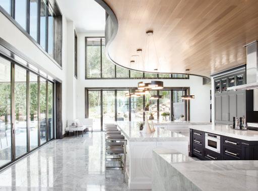
UPWALL DESIGN
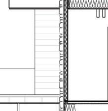
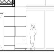
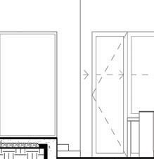
Working almost exclusively in luxury single-family residential architecture and interior design, my time at Upwall Design exposed me to top-of-the-line materials, architectural components, and interior finishes. The client-focused design and construction process was a well-oiled machine, able to balance a large number of projects simultaneously while maintaining the highest level of architectural quality and client interaction. The intimacy of the firm meant that I was able to work on all levels of these projects, and collaborate with architects exercising creativity in contexts verging on a blank check. The magnificent landscape of the Intermountain West provided inspiration and setting, with each home designed to follow the existing features of the existing landscape and capitalize on views from and of these dream homes.

 JACOB CORDONNIER


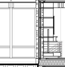

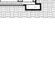
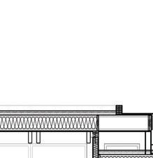

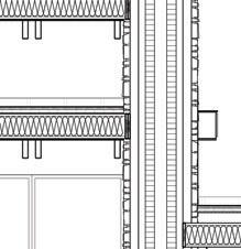
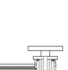

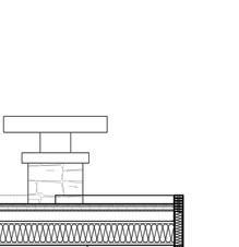


MAIN LEVEL 8508' - 0" MAIN LEVEL 8508' - 0" UPPER LEVEL 8519' - 6" UPPER LEVEL 8519' - 6" LOWER LEVEL 8496' - 0" LOWER LEVEL 8496' - 0" C C B B A A A A3.6 A A3.6 C A3.8 C A3.8 A\V THEATER SUNKEN CONVERSATION STOR. / MECH. STUDY NOELLE GREAT ROOM KITCHEN HEARTH ROOM WINE MASTER WALK-IN 10 40 21 33 29 30 28 32 B A7.2 A A7.7 17 51 G A7.1 37 49 A NEW DESIGN FOR THE : THE ABOVE DRAWINGS AND SPECIFICATIONS AND THE IDEAS, THEREOF SHALL BE COPIED, DISCLOSED TO OTHERS OR USED IN D E S I G N 1930 S. 1100 E. S.L.C. UT 84106 (801)485-070 8 CEDAR EDGE 264 WHITE PINE CANYON LANE PARK CITY, UTAH 84098 A3.7 12 FEBRUARY 2019 LOT 264 THE COLONY 1/4" SECTION KEYNOTES NUMBERDESCRIPTION 40 STONE VENEER W/ 22 GA. TIES AT 16" O.C. EACH WAY W/ NO. WIRE AT 6" O.C. ASSURE WIRE LAPS OVER LEG OF TIE AS REQ. GROUT SOLID. 49STANDING SEAM METAL ROOF. 51 CONTRACTOR TO PROVIDE SAMPLE OF ALL EXTERIOR FINISH MATERIALS TO ARCHITECT INCLUDING, BUT NOT LIMITED TO, MOCK-UP OF ARCHITECTURAL CONCRETE TO BE UTILIZED. KEYNOTES NUMBERDESCRIPTION 5UN-VENTED ROOF ASSEMBLY. SEE A0.0 FOR INSULATION VALUES. 10CHIMNEY CAP AND FLASHING AS REQ. TO ASSURE ADEQUATE MOISTURE PROTECTION. 17ASSURE NO PLUMBING IN EXTERIOR WALL. 21WINDOW SYSTEM. REF. WINDOW SCHEDULE. 28PROVIDE CONT. MOISTURE PROOFING AT ALL BELOW GRADE CONCRETE. 29 CONCRETE FOOTING. REF. FOOTING AND FOUNDATION SCHEDULE. NOTE: ASSURE ALL FOOTINGS ARE ESTABLISHED ON UNDISTURBED NATIVE SOIL CONDITIONS. 30 CONCRETE FOUNDATION WALL. REF. FOUNDATION WALL SCHEDULE FOR REINFORCING REQUIREMENTS. 32EXTEND 6 MIL POLY UNDER FOOTING. 33 6" PERFORATED PVC IN GRAVEL FIELD AT PERIMETER OF FOUNDATION. SLOPE AWAY AT 1/8":12". CONNECT AS REQ. TO STORM SEWER. INSTALL FILTER FABRIC AROUND GRAVEL FIELD. 37 WATER RUNOFF SHALL BE DIRECTED AWAY FROM THE BUILDING. LOTS SHALL BE GRADED TO DRAIN SURFACE WATER AWAY FROM THE FOUNDATION WALLS AT A MINIMUM OF 6 INCHES IN THE FIRST 10 FEET. REVISIONS 100/00/0000 0' 4' 8' 2' 1' SECTION SCALE: 1/4" = 1'-0" B BUILDING GRADING HAS BEEN CHANGED
BOOKS GRILLE ISLAND BENCH LOCKERS ART BENCH ART BENCH R TVABOVE BENCH W OPEN OPEN DOWN DOWN UP A3.1 A P OW C C E E B B D D 7 7 3 3 4 4 5 5 2 2 1 1 6 6 F.P. SINK POCKET SINK HOOKS F.P. SNOW MELT SOAK CENTRAL VAC F.P. MASTER SUITE MASTER SPA LAUND. MUD GEAR HIS HERS HEARTH ROOM PDR. P. DINING GREAT ROOM FOYER COVERED ENTRY STUDY AL FRESCO COVERED OUTDOOR LIVING ELEV. (3+) CAR GARAGE BRIDGE ISLAND COVERED DOWN COVERED ENTRY EL: 5998' 0" EL: 5998' 0" DECK EL: 5997' 8" DECK EL: 5997' 135 135 135 135 135 135 EL: 5998' 0" MECH. GARAGE GUEST APARTMENT WALKA A EL: 5998' MUD POCKET POCKET SINK 118' 6" 35' 1/4" 24' 2 3/4" 40' 0" 18' 6" 6"10 1/2" 33' 10 3/4" 18' 7" 5' 3/4" 22' 6" 14' 6" 3' 0" 13' 2" 5' 4" 199' 11" 26' 0" 53'9" 29' 2" 22' 0" 69' 0" 1' 10" 2' 0" 22' 2" 20'3" 8' 9" 4'0" 20' 9" 6" 16' 6" 5'5 1/4" 8 3/4" 6' 0" 1' 2" 5'5 1/4" 12' 4 3/4" 3'0" 6'6" 19' 0" 8' 6" 13' 6" 2' 6" 19' 0" 3'0" 6' 5" 2' 1" 5 -91/2 4' 1/4" 7' 1/2" 5' 1/4" 6' 3/4" 6" 4' 4" 4' 2" 4' 6" 23' 2" 12' 4" 11' 2" 2' 0" 5' 4" 8' 6" 4' 6" 5' 6" 30' 0" 16' 0" 2' 6" 6-0" 7 81/2" 4' 0" 118' 6" 35' 1/4" 24' 2 3/4" 40' 0" 18' 6" 6" 0" 19' 6" 1' 6" 9 1/4" 8 3/4" 17' 6" 5' 0" 1 3/4" 4 3/4" 3' 1/4" 13' 0" 10' 0" 2" 15' 4" 199' 11" 26' 0" 53'9" 29' 2" 22' 0" 69' 0" 5' 1" 1' 11" 15' 0" 4' 0" 13' 0" 17' 0" 20' 9" 2' 0" 1' 0" 18' 6" 2' 0" 8' 8" 1' 3/4" 4'9" 15' 10 1/4" 12' 11 1/2" 16' 6 3/4" 20' 5 3/4" 19' 0" 1' 11" 2' 0" 28' 6" (4) CAR GARAGE SLEEP GUEST ENTRY D D 5 5 DOWN OPEN TO BELOW ELEV. F.P. RAIL DECK UPPER LEVEL EL: 6009' 6" DECK EL: 6009' 6" 7 81/2" 5 91/2" 591/2 7 41/4" 2' 0" 8' 8" 1' 3/4" 5' 2 1/4" 135 135° 135 135 135 135 5' 1/4" 7' 1/4" 4' 1/4" 1 1/4" 7' 1/2" 5 1/4" 5' 5 1/4" 1' 2" 12' 2" 16' 6" 10" A NEW DESIGN FOR THE : THE ABOVE DRAWINGS AND SPECIFICATIONS AND THE IDEAS, THEREOF SHALL BE COPIED, DISCLOSED TO OTHERS OR USED IN D E S I G N 1930 S. 1100 E. S.L.C. UT 84106 (801)485-070 8 LOW RESIDENCE 1581 STONE HOLLOW DR. BOUNTIFUL, UT 84010 A2.2 1 APRIL 2019 LOT 603 STONE RIDGE PLAT F 3/32" MAIN/UPPER LEVEL PLANS 0' 2 4' 6' 1 2' PLAN SCALE: 3/32" = 1'-0" MAIN LEVEL REVISIONS 0' 8' 16' 4' 2' PLAN SCALE: 3/32" = 1'-0" UPPER LEVEL
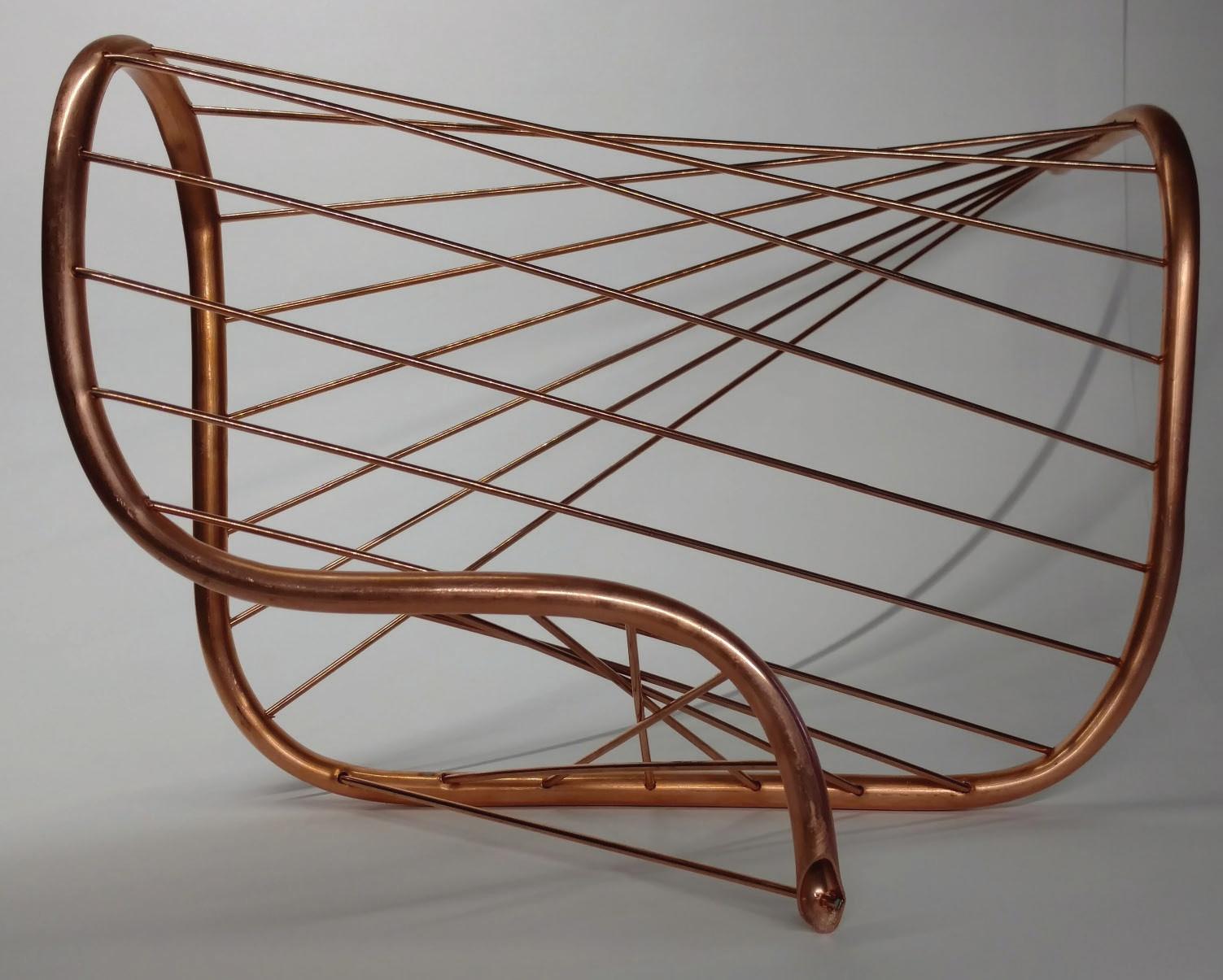
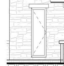
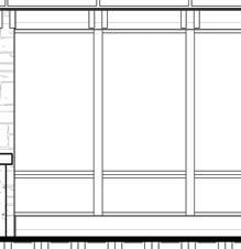
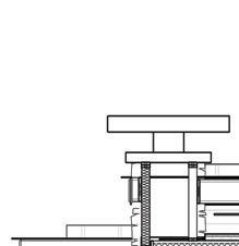
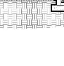
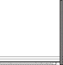
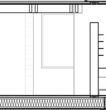
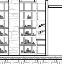
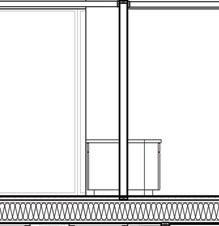
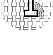
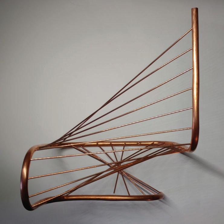
Material Articulation invited an exploration of a particular medium. I investigated copper through its plasticity, strength, deformation, and reflectivity. The geographical history of Utah provided inspiration for this selection, with copper mining forming its historical economic backbone. Exciting architectural applications of the metal are frequent in the state: facades, fascias, interior accents, and more. Design followed discovery; new forms and movements emerged as I grew to understand the opportunities and limitations of the material in different formats such as tubing, wire, and rods. The final design sought to express copper’s advantages visually. A winding primary form displays both brilliant richness of color and graceful flexibility. Interlacing rods suggest delicate strength acting in both tension and compression.

opposite: elevation above: material study right: plan
BODY+TIME
HANNAH VAHN
TROPIC PAVILION
Collaboration:Anna Creatura,Carlyn Gilbertson,Tina Athari
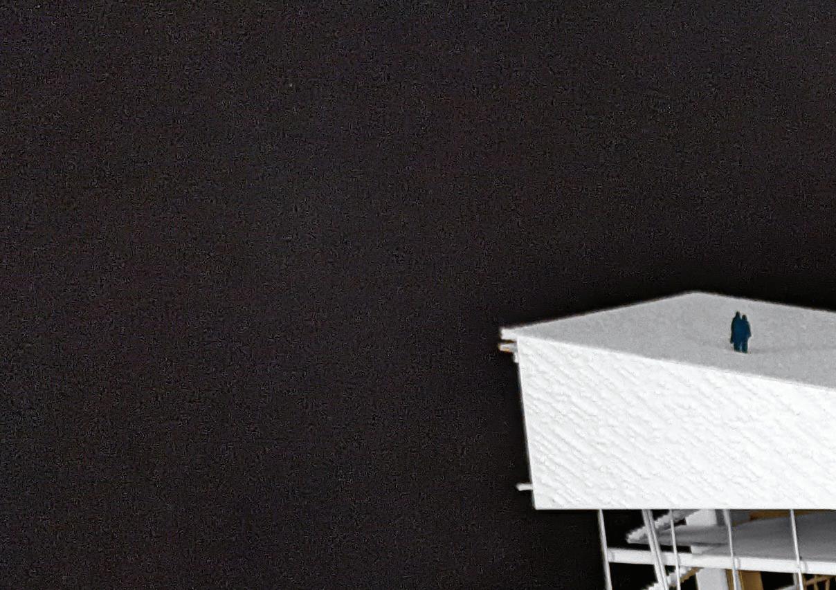
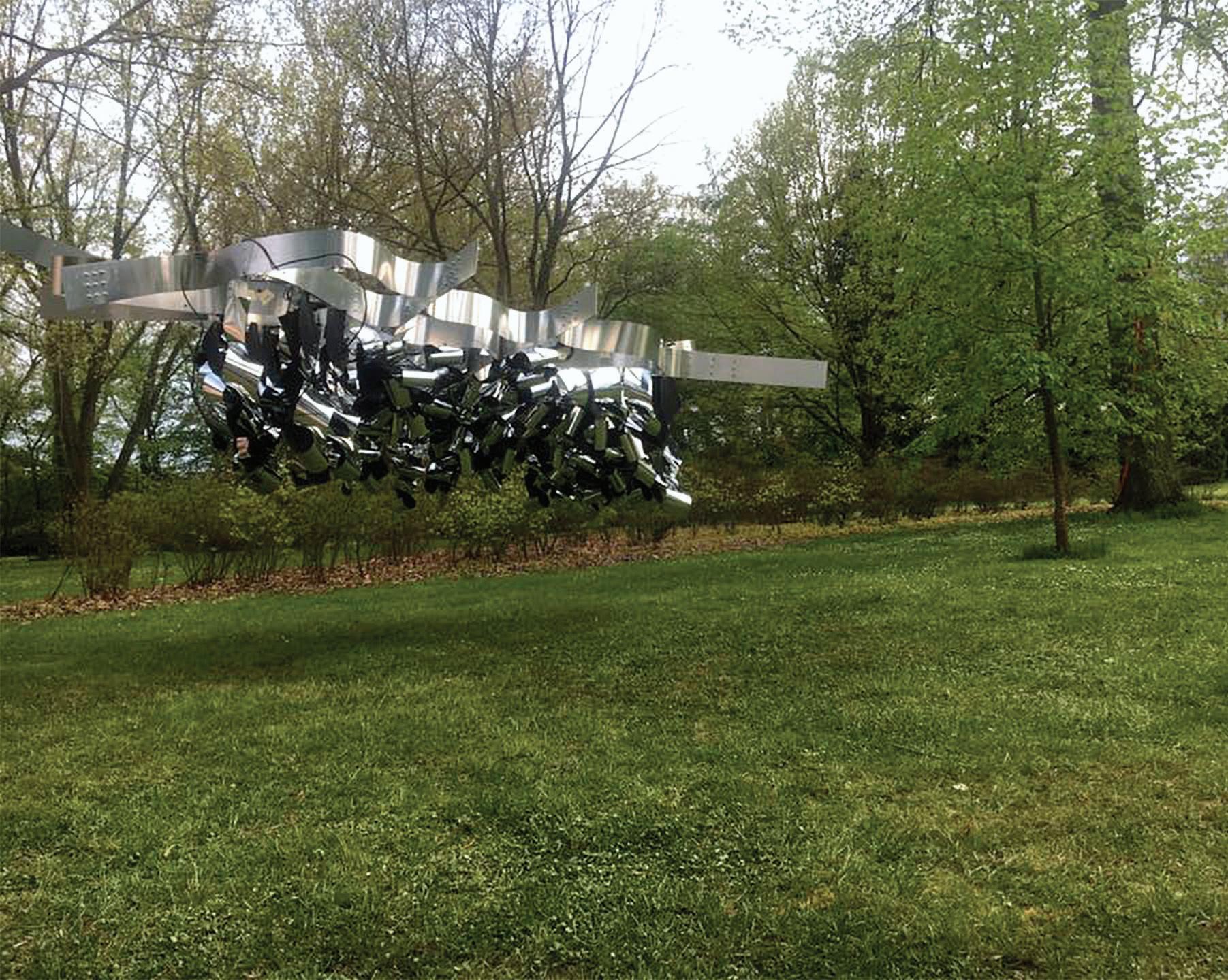
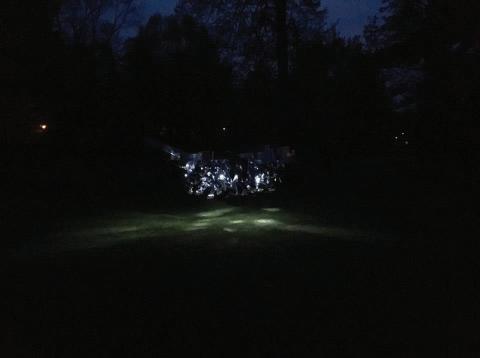
Architectural kinetics can naturally engage viewers and inhabitants. Movement draws the eye and can heighten engagement in a space. This pavilion commissioned by the Anifilm Film Festival - a showcase of international animated film. A playful application of kinetics was chosen to implicate the imagination and dynamism of the format. With an eye on budgetary constraints, I designed and built a mechanical system c omprised of 3D-printed and lasercut mechanics was linked to data on inhabitant location. Long, linear components contract as those nearby draw closer into a compact, mirrored flower. Clusters of these components shrink away, forming and individualized semiprivate space.
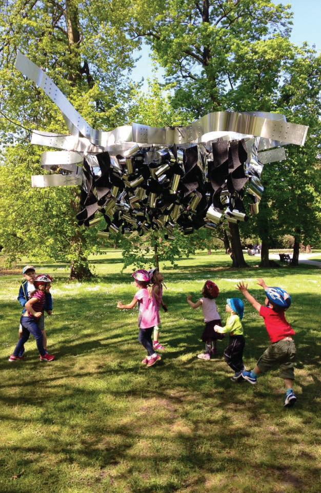 Opposite: installed pavilion
Above: night view
Right: interaction
MARTIN GSANDTER
Opposite: installed pavilion
Above: night view
Right: interaction
MARTIN GSANDTER

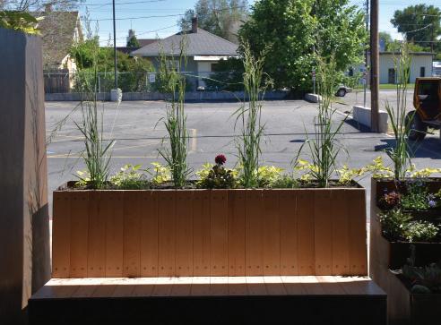
Collaboration: Christian Kinservik
An unused office patio was conv erted into a private, peaceful garden for client meetings, team lunches, and individual work. In this project, I designed and constructed four COR-TEN steel planter boxes from raw materials. Flower and shrub selection was an early step in the design process, which focused on a grass wall for privacy, allowing the office to conduct private meetings with open windows and a garden view. This project was entirely self-motivated and implemented. I developed many skills in metal- and wood-working to complete this project. The goal was for these planters to act as a composition, each box displaying unique aspects while establishing continuity and rhythm.
STEEL OASIS
opposite: entry planter
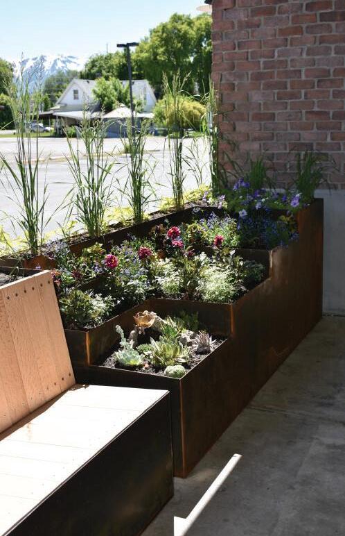
above: white oak bench
right: ornamental bed
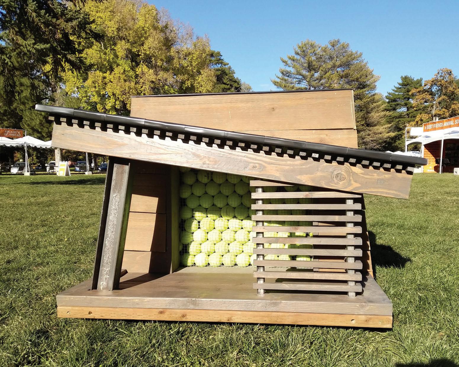
Collaboration: Jacob Cordonnier, Josh Riffe, Brendan Wolfe
Best in Show - Salt Lake Barkitecture Competition 2019

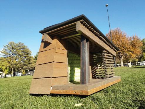
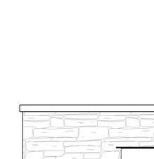
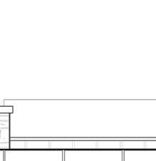
This luxury doghouse was designed for the Best Friends Animal Society fundraising doghouse design competition. Architectural design firms partnered with a contractor and worked under a very limited budget to design a doghouse for auction. Materials were procured from an active construction site from what was available. Inspired by local mountain contemporary design, the wood-clad tower anchors a dramatically projecting roof, supported by a prominent raw steel beam. A recessed tennis ball accent wall is accessible through a storage compartment on the side of the tower.
HABITAT K-9
opposite: dog’s-eye
above: elevation
right: good boy


PHOTOGRAPHY


andrewjmickelson@gmail.com @andrewjmickelson (435) 881-9858 THANK YOU