
Service Manual XR Forward Reach Forklifts
Manufacturing, LLC
Bonanza Road
IMPORTANT Read and understand this manual before operating or performing maintenance on these forklifts. Copyright © 2011 – Xtreme Manufacturing, LLC P/N 24933-000 Rev 02 – 08/11 Xtreme Xr Forward Reach Forklift Service Manual Full download: http://manualplace.com/download/xtreme-xr-forward-reach-forklift-service-manual/ This is the cut pages sample. Download all 280 page(s) at: ManualPlace.com
Xtreme
1415 West
Las Vegas, NV 89106 (702) 858-2404 (702) 646-2196 (fax) www.xtrememanufacturing.com
Ask your supervisor to explain any operation, maintenance, or safety information that you do not fully understand.
Untrained personnel can cause death or severe injury. Do not operate or perform maintenance on a forklift until you have read and understand:
• The Operation and Safety Manual for the forklift.
• Chapter 2 of this Service Manual.
• The safety labels affixed to the forklift.
• Your employer's applicable work rules regarding the safety, operation, and maintenance of the forklift.
• Applicable federal, state, or local government regulations.
Untrained personnel can cause death or severe injury. Do not operate or work on a forklift until you have been trained in the safe operation and maintenance of the forklift.
– REPLACEMENT OF MANUALS –
Contact Xtreme Manufacturing, LLC, to obtain replacement Operation and Safety Manuals, Owner’s Service Manuals, Service Manuals, or Illustrated Parts Catalogs.
Xtreme Manufacturing, LLC 1415 West Bonanza Road Las Vegas, NV 89106 (702) 851-3750 xtrememanufacturing.com
List of Effective Pages
This manual consists of 280 pages as listed below:
Front cover page
Inside front cover page Title page
Pages A through B Pages i through x Pages 1-1 through 1-32 Pages 2-1 through 2-22 Pages 3-1 through 3-6 Pages 4-1 through 4-6 Pages 5-1 through 5-34 Pages 6-1 through 6-14 Pages 7-1 through 7-8 Pages 8-1 through 8-48 Pages 9-1 through 9-22 Pages 10-1 through 10-32 Pages 11-1 through 11-6 Pages 12-1 through 12-6 Pages Index 1 through Index 9 Pages A-1 through A-20
Inside back cover page Back cover page
Copyright © 2011 – Xtreme Manufacturing Co.
List of Effective Pages
Service Manual Rev 02 – 08/11 A P/N 24933-000
Service Bulletins
The following Service Bulletins have been incorporated in this manual:
Number Title Comments
Service Bulletins
Service
Rev 02 – 08/11 B P/N 24933-000
Manual
Table of Contents Table of Contents PARA. TITLE PAGE List of Effective Pages ................................................................................................... A Service Bulletins ............................................................................................................ B Table of Contents ........................................................................................................... i List of Illustrations ........................................................................................................ vi List of Tables ................................................................................................................. ix SECTION 1 – GENERAL INFORMATION & SPECIFICATIONS ....................................... 1-1 1-1 Scope of Manual......................................................................................................... 1-1 1-2 Applicability................................................................................................................. 1-1 1-3 Service Bulletins.......................................................................................................... 1-1 1-4 Related Technical Documentation.............................................................................. 1-2 1-5 Forklift Nomenclature.................................................................................................. 1-2 1-6 Component Data Plates .............................................................................................. 1-9 1-7 Lubricants and Fluids.................................................................................................. 1-13 1-8 Filters and Strainers.................................................................................................... 1-14 1-9 Forklift and Engine Specifications............................................................................... 1-15 1-10 Torque Wrench Use.................................................................................................... 1-29 1-11 Cap Screw Torque Values.......................................................................................... 1-29 SECTION 2 – MAINTENANCE & OPERATION SAFETY ................................................. 2-1 2-1 General....................................................................................................................... 2-1 2-2 Safety Signal Words.................................................................................................... 2-1 2-3 Notes........................................................................................................................... 2-1 2-4 Safety Symbols........................................................................................................... 2-2 2-5 Lockout/Tagout Procedure.......................................................................................... 2-6 2-6 General Maintenance Precautions.............................................................................. 2-7 2-7 Viton Seals.................................................................................................................. 2-7 2-8 Using Compressed Air Safely..................................................................................... 2-8 2-9 Battery Handling and Maintenance............................................................................. 2-8 2-10 Engine Operation and Maintenance........................................................................... 2-10 2-11 Fuel Handling and Maintenance................................................................................. 2-11 2-12 California Proposition 65 Warnings............................................................................. 2-11 2-13 Functional Tests.......................................................................................................... 2-11 2-14 Safe Operation Checklist............................................................................................ 2-12 2-15 Functional Test Checklist............................................................................................ 2-13 2-16 Load Handling............................................................................................................. 2-14 Service Manual Rev 02 – 08/11 i P/N 24933-000
Table of Contents Table of Contents – Cont. PARA. TITLE PAGE 2-17 Picking Up a Load....................................................................................................... 2-16 2-18 Carrying a Load........................................................................................................... 2-16 2-19 Placing a Load............................................................................................................ 2-16 2-20 Load Shift.................................................................................................................... 2-17 2-21 Proper Use of Forks.................................................................................................... 2-17 2-22 Prohibited Practices.................................................................................................... 2-17 2-23 Operator Hand Signals ............................................................................................... 2-18 2-24 Safety Labels.............................................................................................................. 2-19 SECTION 3 – MAINTENANCE SCHEDULE .................................................................... 3-1 3-1 Establishing a Preventive Maintenance Program....................................................... 3-1 3-2 Long-Interval Maintenance Requirements.................................................................. 3-6 SECTION 4 – AXLE CYLINDE R AND OUTRIGGER LUBRICATION ................................ 4-1 4-1 General Maintenance Safety...................................................................................... 4-1 4-2 Using a Grease Gun................................................................................................... 4-1 4-3 Lubricate Axle Cylinders and Outriggers.................................................................... 4-2 SECTION 5 – ENGINE ................................................................................................... 5-1 5-1 General Maintenance Safety...................................................................................... 5-1 5-2 Check Engine Oil Level............................................................................................... 5-1 5-3 Check Engine Coolant Level....................................................................................... 5-3 5-4 Check for Oil and Coolant Leaks................................................................................ 5-5 5-5 Check for Water in Fuel-Water Separator................................................................... 5-6 5-6 Empty Air Filter Dust Cup........................................................................................... 5-8 5-7 Check Condition and Tension of Drive Belts.............................................................. 5-10 5-8 Change Engine Oil ...................................................................................................... 5-10 5-9 Replace Oil Filters....................................................................................................... 5-13 5-10 Replace Fuel Filter...................................................................................................... 5-16 5-11 Check Specific Gravity of Coolant.............................................................................. 5-18 5-12 Drain and Flush Cooling System................................................................................ 5-20 5-13 Replace Air Filter......................................................................................................... 5-22 5-14 Check Air Filter............................................................................................................ 5-24 5-15 Check Condition and Tension of Drive Belts.............................................................. 5-25 5-16 Check and Adjust Valve Tip Clearances..................................................................... 5-27 5-17 Check Engine Hoses and Connections...................................................................... 5-29 Service Manual Rev 02 – 08/11 ii P/N 24933-000
Table of Contents Table of Contents – Cont.
TITLE PAGE 5-18 Check Radiator Hoses and Connections.................................................................... 5-30 5-19 Check Engine Wiring and Connections...................................................................... 5-31 5-20 Check for Oil, Coolant, and Fuel Leaks...................................................................... 5-32 SECTION 6 – TRANSMISSION, AXLES, & DRIVE SHAFTS ........................................... 6-1 6-1 General Maintenance Safety...................................................................................... 6-1 6-2 Using a Grease Gun................................................................................................... 6-1 6-3 Lubricate Axle Grease Fittings.................................................................................... 6-2 6-4 Lubricate Drive Shafts................................................................................................. 6-4 6-5 Replace Transmission Filters and Fluids.................................................................... 6-6 6-6 Check Axle Oil Level................................................................................................... 6-8 6-7 Check Wheel End Oil Level ........................................................................................ 6-11 6-8 Drain and Fill Axle Wheel End.................................................................................... 6-13 SECTION 7 – WHEELS & TIRES ................................................................................... 7-1 7-1 General Maintenance Safety...................................................................................... 7-1 7-2 Check Wheel Lug Nut Torque..................................................................................... 7-1 7-3 Inspect Wheel/Tire Assembly..................................................................................... 7-3 7-4 Replace Wheel/Tire Assembly.................................................................................... 7-4 7-5 Replace Tire................................................................................................................ 7-7 SECTION 8 – HYDRAULIC SYSTEM .............................................................................. 8-1 8-1 General Maintenance Safety...................................................................................... 8-1 8-2 Hydraulics Maintenance Safety and Precautions....................................................... 8-1 8-3 Handling Hydraulic Fluid............................................................................................. 8-2 8-4 Making Leak-Free Connections.................................................................................. 8-2 8-4-1 Hose and Tubing Installation Practices....................................................................... 8-2 8-4-2 Operating Conditions.................................................................................................. 8-2 8-4-3 Maintenance Practices................................................................................................ 8-3 8-5 Keeping the Hydraulic System Clean......................................................................... 8-4 8-6 Check Hydraulic Fluid Level....................................................................................... 8-6 8-7 Change Hydraulic Fluid............................................................................................... 8-8 8-8 Replace Suction Strainer ............................................................................................ 8-10 8-9 Clean Hydraulic Reservoir Strainer............................................................................. 8-12 8-10 Replace Air Breather................................................................................................... 8-14 8-11 Replace High-Pressure Filter...................................................................................... 8-16 8-12 Replace Return Line Filter.......................................................................................... 8-19 Service Manual Rev 02 – 08/11 iii P/N 24933-000
PARA.
Table of Contents Table of Contents – Cont.
TITLE PAGE 8-13 Taking Hydraulic Fluid Sample................................................................................... 8-21 8-14 Replacing a Hose........................................................................................................ 8-24 8-15 Tightening Loose Fittings............................................................................................ 8-27 8-16 Replace Cartridge Valve ............................................................................................. 8-27 8-17 Replace Cartridge Valve Solenoid.............................................................................. 8-30 8-18 Location of Hydraulic Components............................................................................. 8-32 8-19 Distribution Manifold Hose Connections..................................................................... 8-32 8-20 Maintenance Requirements for Failed Pump............................................................. 8-47 SECTION 9 – ELECTRICAL SYSTEM ........................................................................... 9-1 9-1 General Maintenance Safety...................................................................................... 9-1 9-2 Battery Safety.............................................................................................................. 9-1 9-3 Battery Description...................................................................................................... 9-3 9-4 Battery Cable Description........................................................................................... 9-3 9-5 Check Condition of Battery and Cables...................................................................... 9-3 9-6 Replace Battery........................................................................................................... 9-4 9-7 Inspect and Clean Battery........................................................................................... 9-8 9-8 Install Auxiliary Battery................................................................................................ 9-9 9-9 Electrical Center Assembly......................................................................................... 9-11 9-10 Engine Relay Assembly.............................................................................................. 9-16 9-11 Replace a Relay.......................................................................................................... 9-18 9-12 Replace a Fuse........................................................................................................... 9-20 SECTION 10 – BOOM & ATTACHMENTS ...................................................................... 10-1 10-1 General Maintenance Safety...................................................................................... 10-1 10-2 Using a Grease Gun................................................................................................... 10-1 10-3 Boom and Attachment Lubrication.............................................................................. 10-2 10-4 Lubricate Boom Extend Chain.................................................................................... 10-6 10-5 Inspect Boom Chains.................................................................................................. 10-7 10-5-1 Chain Nomenclature................................................................................................... 10-8 10-5-2 Visually Inspect Chain................................................................................................. 10-8 10-5-3 Measure Chain Edge Wear......................................................................................... 10-11 10-5-4 Measure Chain Elongation.......................................................................................... 10-13 10-6 Check and Adjust Boom Chain Tension..................................................................... 10-15 10-7 Slide Blocks................................................................................................................. 10-16 10-8 Inspect Slide Blocks.................................................................................................... 10-16 10-9 Replace Slide Blocks.................................................................................................. 10-20 Service Manual Rev 02 – 08/11 iv P/N 24933-000
PARA.
Table of Contents Table of Contents – Cont. PARA. TITLE PAGE 10-10 Inspect Boom Rollers.................................................................................................. 10-21 10-11 Fork Nomenclature...................................................................................................... 10-24 10-12 Measure Fork Flank Wear.......................................................................................... 10-26 10-13 Fork Inspection............................................................................................................ 10-28 10-14 Manually Retracting and Lowering Boom................................................................... 10-29 SECTION 11 – CHECK-OUT PROCEDURES .................................................................. 11-1 11-1 Check Operation of Rear Axle Stabilization System................................................... 11-1 SECTION 12 – STORAGE & TRANSPORTATION .......................................................... 12-1 12-1 General Maintenance Safety...................................................................................... 12-1 12-2 Preparing Engine for Long-Term Storage................................................................... 12-1 12-3 Preparing Forklift for Long-Term Storage................................................................... 12-4 12-4 Transporting Forklift.................................................................................................... 12-5 APPENDIX – MAINTENANCE FORMS AND SAFETY TAGS .......................................... A-1 A-1 Preventive Maintenance and History Logs................................................................. A-1 A-2 Pre-Operation Checklist.............................................................................................. A-1 A-3 Safety Tags................................................................................................................. A-1 Maintenance Schedule...................................................................................................................... A-2 Maintenance History Log.................................................................................................................. A-8 Fork Inspection Log........................................................................................................................... A-11 Pre-Operation Checklist.................................................................................................................... A-13 Grease Fittings List........................................................................................................................... A-15 Danger Tags..................................................................................................................................... A-16 Condition Tags.................................................................................................................................. A-17 Notes................................................................................................................................................. A-18 Service Manual Rev 02 – 08/11 v P/N 24933-000
Table of Contents List of Figures
TITLE PAGE 1-1 Forklift Nomenclature.................................................................................................. 1-3 1-2 Forklift Covers............................................................................................................. 1-6 1-3 Forklift Cab.................................................................................................................. 1-7 1-4 Front Control Panel ..................................................................................................... 1-8 1-5 Side Control Console.................................................................................................. 1-9 1-6 Location of Chassis and Engine Data Plates.............................................................. 1-10 1-7 Location of Transmission Data Plates........................................................................ 1-11 1-8 Location of Axle Data Plates....................................................................................... 1-12 1-9 SAE Grade 8 Bolt Markings ........................................................................................ 1-31 2-1 Danger and Condition Tags........................................................................................ 2-6 2-2 Battery Disconnect Switch.......................................................................................... 2-7 2-3 Operator Hand Signals ............................................................................................... 2-18 2-4 Safety Labels.............................................................................................................. 2-19 3-1 Forklift Hourmeter....................................................................................................... 3-1 4-1 Front and Rear Axle Cylinder Grease Fittings............................................................ 4-3 4-2 Outrigger Grease Fittings – XR1245/1255/1267/1270/2045/2450 ............................. 4-4 5-1 Engine Oil Fill Cap and Dipstick.................................................................................. 5-2 5-2 Coolant Level Indicator............................................................................................... 5-4 5-3 Radiator....................................................................................................................... 5-5 5-4 Fuel-Water Separator ................................................................................................. 5-7 5-5 Engine Air Filter Assembly.......................................................................................... 5-9 5-6 Oil Drain Plug and Dipstick......................................................................................... 5-12 5-7 Recommended Engine Oil Viscosity Grades.............................................................. 5-12 5-8 Element-Type Oil Filter ............................................................................................... 5-14 5-9 Canister-Type Oil Filter............................................................................................... 5-15 5-10 Fuel Filter Element...................................................................................................... 5-17 5-11 Coolant Recovery Tank and Radiator Drain............................................................... 5-19 5-12 Specific Gravity Chart................................................................................................. 5-20 5-13 Cylinder Block Drain Plug........................................................................................... 5-22 5-14 Checking Drive Belt Tension....................................................................................... 5-26 5-15 Checking and Adjusting Engine Valve Clearances..................................................... 5-28 5-16 Radiator Hoses and Connections............................................................................... 5-31 Service Manual Rev 02 – 08/11 vi P/N 24933-000
FIGURE
Table of Contents
of
6-1 Axle Grease Fittings....................................................................................................
6-2 Drive Shaft Grease Fittings.........................................................................................
6-3 Transmission Plugs and Filters...................................................................................
6-4 Axle Differential and Trumpet Fluid Levels.................................................................
6-5 Axle Wheel End...........................................................................................................
7-1 Lug Nut Torque Check Sequence............................................................................... 7-2 7-2 Wheel/Tire Assembly..................................................................................................
7-3 Wheel Lug Nut Tightening Sequence.........................................................................
8-1 Making Leak-Free Connections..................................................................................
8-2 Hydraulic Filtration System.........................................................................................
8-3 Hydraulic Reservoir Sight Gauge................................................................................
8-4 Hydraulic Reservoir Fill Cap.......................................................................................
8-5 Hydraulic Reservoir.....................................................................................................
8-6 Hydraulic Reservoir Strainer.......................................................................................
8-7 Air Breather.................................................................................................................
8-8 Location of Hydraulic Filters........................................................................................
8-9 High-Pressure Filter....................................................................................................
8-10 Return Line Filter.........................................................................................................
8-11 Taking Hydraulic Fluid Sample...................................................................................
8-12 Hose Installation Guidelines....................................................................................... 8-26 8-13 Cartridge Valve Solenoid............................................................................................ 8-31 8-14 Location of Hydraulic Components............................................................................. 8-32 8-15 Distribution Manifold Hose Connections – Model XR842........................................... 8-37 8-16 Distribution Manifold Hose Connections – Model XR1045......................................... 8-39 8-17 Distribution Manifold Hose Connections – Model XR1245......................................... 8-41 8-18 Distribution Manifold Hose Connections – Model XR1255......................................... 8-43 9-1 Battery and Cables...................................................................................................... 9-4 9-2 Battery Installation....................................................................................................... 9-6 9-3 Auxiliary Battery Installation........................................................................................ 9-10 9-4 Connecting Auxiliary Battery....................................................................................... 9-11 9-5 Electrical Center Relays and Fuses............................................................................ 9-12 9-6 Engine Relay Assembly.............................................................................................. 9-17 9-7 Correct Installation of Relays B through G, P/N 12068567 ........................................ 9-18 Service Manual Rev 02 – 08/11 vii P/N 24933-000
List
Figures – Cont. FIGURE TITLE PAGE
6-3
6-5
6-7
6-10
6-12
7-4
7-6
8-3
8-5
8-7
8-8
8-10
8-12
8-15
8-17
8-18
8-20
8-23
List of Figures – Cont.
Table of Contents
Disconnect Switch..........................................................................................
Condition.......................................................................................
Lubrication..............................................................................
Chain Lubrication.................................................................................
Inspection...........................................................................................
Wear Measurement.................................................................................
Measurement..................................................................................
...............................................................................
Locations
Service Manual Rev 02 – 08/11 viii P/N 24933-000
FIGURE TITLE PAGE 9-8 Battery
9-20 9-9 Determining Fuse
9-21 10-1 Boom and Attachment
10-3 10-2 Boom Extend
10-7 10-3 Chain Nomenclature................................................................................................... 10-8 10-4 Chain Damage
10-10 10-5 Chain Edge
10-12 10-6 Chain Elongation
10-14 10-7 Boom Chain Tension Adjustment
10-16 10-8 Boom Slide Blocks...................................................................................................... 10-18 10-9 Boom Roller Inspection............................................................................................... 10-22 10-10 Location of Boom Rollers............................................................................................ 10-23 10-11 Fork Nomenclature...................................................................................................... 10-24 10-12 Measuring Fork Flank Wear........................................................................................ 10-27 10-13 Boom Lift and Extend Cylinder Manual Lowering Valves........................................... 10-31 11-1 Boom Angle Indicator.................................................................................................. 11-2 11-2 Frame Level Indicator................................................................................................. 11-3 12-1 Tie-Down Point
........................................................................................... 12-6
TITLE
Table of Contents
List of Tables
Documentation..............................................................................
Fluids..................................................................................................
Numbers................................................................................
Values –
2-1 Safety Symbols...........................................................................................................
3-1 Preventive Maintenance – After First 50 Hours of Operation.....................................
3-2 Preventive Maintenance – After First 250 Hours of Operation................................... 3-2 3-3 Preventive Maintenance – After Every 8 Hours of Operation..................................... 3-3 3-4 Preventive Maintenance – After Every 50 Hours of Operation................................... 3-3 3-5 Preventive Maintenance – After Every 250 Hours of Operation ................................. 3-4 3-6 Preventive Maintenance – After Every 500 Hours of Operation ................................. 3-4 3-7 Preventive Maintenance – After Every 1,000 Hours of Operation .............................. 3-5 3-8 Preventive Maintenance – After Every 2,000 Hours of Operation .............................. 3-6 3-9 Long-Interval Maintenance Requirements.................................................................. 3-6 5-1 Cylinder and Valve Numbers ...................................................................................... 5-28 7-1 Forklift Operating Weights.......................................................................................... 7-5 7-2 Wheel and Tire Specifications.................................................................................... 7-7 8-1 Hose Connector Torque Values.................................................................................. 8-27 8-2 Boom Isolation Manifold Valve Torque Values........................................................... 8-45 Service Manual Rev 02 – 08/11 ix P/N 24933-000
TABLE
PAGE 1-1 Related Technical
1-2 1-2 Lubricants and
1-13 1-3 Filter and Strainer Part
1-14 1-4 Model XR620/621 Specifications................................................................................ 1-15 1-5 Model XR842 Specifications....................................................................................... 1-16 1-6 Model XR1045 Specifications..................................................................................... 1-17 1-7 Model XR1245 Specifications..................................................................................... 1-18 1-8 Model XR1255 Specifications..................................................................................... 1-19 1-9 Model XR1267 Specifications..................................................................................... 1-20 1-10 Model XR1270 Specifications..................................................................................... 1-21 1-11 Model XR1534 Specifications..................................................................................... 1-22 1-12 Model XR1642 Specifications..................................................................................... 1-23 1-13 Model XR2034 Specifications..................................................................................... 1-24 1-14 Model XR2045 Specifications..................................................................................... 1-25 1-15 Model XR2450 Specifications..................................................................................... 1-26 1-16 Model XR3034 Specifications..................................................................................... 1-27 1-17 Engine Specifications.................................................................................................. 1-28 1-18 Tightening Torque
Cap Screws................................................................... 1-30
2-2
3-1
Table of Contents Service Manual Rev 02 – 08/11 x P/N 24933-000
8-3 Rear Axle Cylinder Valve Torque Values................................................................... 8-45 8-4 Distribution Manifold Torque Values (XR842/1045).................................................. 8-45 8-5 Distribution Manifold Torque Values (XR1245/1255) ................................................ 8-46 9-1 Electrical Center Relays.............................................................................................. 9-15 9-2 Electrical Center Fuses and Circuit Breaker............................................................... 9-15 9-3 Fuse Block Fuses........................................................................................................ 9-16 9-4 Engine Relay Assembly Relays and Fuse.................................................................. 9-16 10-1 Fork Nomenclature...................................................................................................... 10-24 12-1 Forklift Operating Weights.......................................................................................... 12-5
List of Tables – Cont. TABLE TITLE PAGE
Section 1
General Information & Specifications
1-1 SCOPE OF MANUAL
This manual provides operation and maintenance information and procedures intended for use by the owner and/or operator of the forklift. For detailed, specific operating instructions, refer to the applicable Operation and Safety Manual for the specific model forklift. For detailed maintenance and troubleshooting information and schematic diagrams, refer to the Service Manual.
1-2 APPLICABILITY
This Owner's Service Manual applies to the following model rough-terrain, forward-reach forklifts manufactured by Xtreme Manufacturing:
XR620 XR1270
XR621 XR1534
XR842 XR1642
XR1045 XR2034
XR1245 XR2045
XR1255 XR2450
XR1267 XR3034
1-3 SERVICE BULLETINS
Service Bulletins are issued by Xtreme Manufacturing, LLC to help mechanics diagnose and repair forklift problems discovered during the manufacturing process or reported by owners and repair shops. There are two types of Service Bulletins:
• Safety Service Bulletin: This type of bulletin is issued for safety problems that affect the safe operation of the forklift. An example would be "Parking brake is weak."
• Service Bulletin: This type of bulletin is issued for non-safety problems that affect the reliability or performance of the forklift of forklift subsystem. An example would be "Engine idles rough."
Perform the following steps when you have received a service bulletin:
• Carefully read and analyze the service bulletin.
• Determine if the service bulletin applies to your forklift(s).
General Information & Specifications
Service Manual Rev 02 –
1-1 P/N 24933-000
08/11
• Determine if you have the skills, tools, equipment, and personnel required to comply with the Service Bulletin. If not, contact a reputable service center for assistance.
• Comply with the inspection or maintenance procedure contained in the Service Bulletin.
• For Safety Service Bulletins, complete the enclosed response form and return to:
Xtreme Manufacturing Co. 1415 West Bonanza Road Las Vegas, NV 89106
1-4 RELATED TECHNICAL DOCUMENTATION
Refer to Table 1-1 for a listing of technical documentation related to the safety, operation, repair, and overhaul of the forklifts.
Table 1-1. Related Technical Documentation
Item
Users Manual – 1100 Series Engines Models RE, RF, RG, RH, RJ, RK
Manufacturer/Agency Part No.
Perkins Engines, Inc. TPD 1477
Repair Manual – Transmission Model TLB2 4WD Cararro SPA CA357151
Spare Parts List – Transmission Model TLB2 (Ref. 141166) Cararro SPA CA355311
Repair Manual – Axle Model 26.28M Cararro SPA CA355038
Spare Parts List – Axle Model 26.28M (Ref. 136534) Cararro SPA CA355038
Spare Parts List – Axle Model 26.28M (Ref. 142200) Cararro SPA CA355443
Service Manual – K3VL Swash-Plate Type Axial Piston Pump Kawasaki Precision Machinery of America 03890327-E
Maintenance and Repair Instruction Manual Drive Axle Type 212
Safety Standard for Rough Terrain Forklift Trucks
1-5 FORKLIFT NOMENCLATURE
DANA ITALIA SpA MO212S10
American Society of Mechanical Engineers ASME B56.6-2002
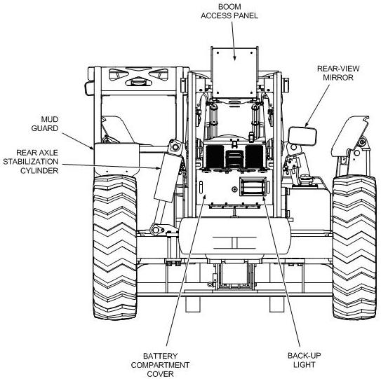
Refer to Figure 1-1 for a depiction of forklift components and nomenclature. All forklifts are basically the same except that models XR1245, XR1255, XR1267, XR1270, XR2045, and XR2450 are equipped with left and right outriggers.
Service Manual Rev 02 – 08/11
P/N 24933-000
General Information & Specifications
1-2
Figure 1-1. Forklift Nomenclature (Sheet 1 of 3)
General Information & Specifications
Service Manual Rev 02 – 08/11 1-3 P/N 24933-000
FRAME SWAY CYLINDER
OUTRIGGER PAD
Figure 1-1. Forklift Nomenclature (Sheet 2 of 3)
FOAM- FILLED TIRE
General Information & Specifications
Service Manual Rev 02 – 08/11 1-4 P/N 24933-000
Figure 1-1. Forklift Nomenclature (Sheet 3 of 3)
General Information & Specifications
Service Manual Rev 02 – 08/11 1-5 P/N 24933-000
Xtreme Xr Forward Reach Forklift Service Manual
Full download: http://manualplace.com/download/xtreme-xr-forward-reach-forklift-service-manual/
Figure 1-2. Forklift Covers
Service Manual Rev 02 – 08/11 1-6 P/N 24933-000
This is the cut pages sample. Download all 280 page(s) at: ManualPlace.com

General Information & Specifications
