7 minute read
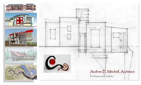
Andrew e Mitchell Architect Portfolio


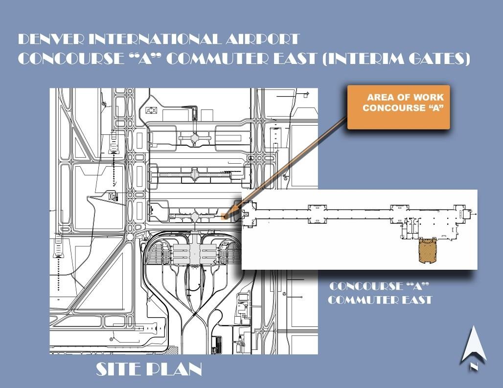
Project: Denver International Airport (DIA) - Interim Gate at Concourse ‘A’, Commuter East.
Denver, Colorado
Principal in Charge: Jeffery Reddy
Project Manager/Senior Project Architect: Andrew Mitchell
Project Design: Andrew Mitchell
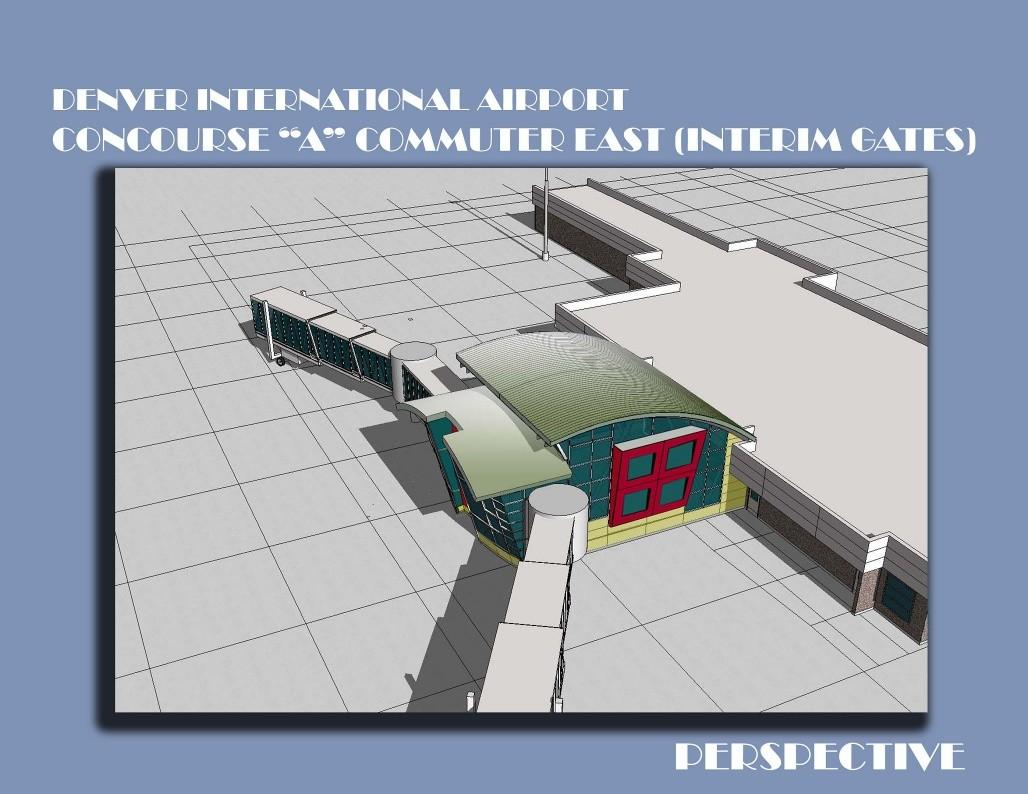
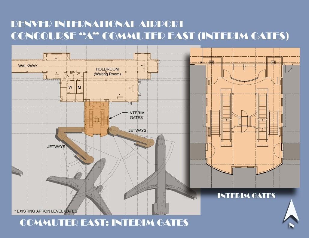
The current Concourse ‘A’ Commuter East facility provides apron level walk-on access to commuter aircraft. Frontier Airlines required service via regional jets from this wing of the concourse. These jets are of such a size and design that passenger access to the aircraft via the apron is undesirable. The planned facility is designed to address this issue by providing new gates with access to planes via ‘apron drive loading bridges’. (Loading bridges that load from the first story apron level) Vertical circulation in the form of escalators, a chair lift and stairs is provided to give access to the loading bridges at an elevated floor level of the new addition.

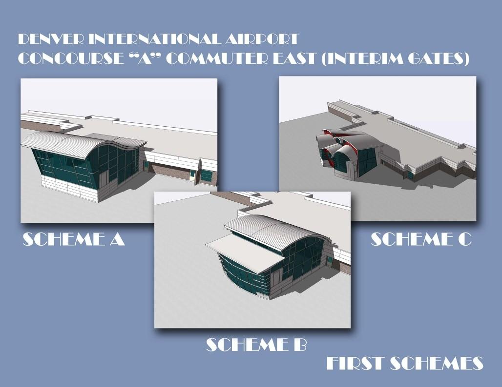
Design aesthetics were to be to the level of the existing main terminal and concourse. Elements of this design include:
Strategic use of glazing coupled with a light and exposed structure creates a ‘glass pavilion’ feel to the space.
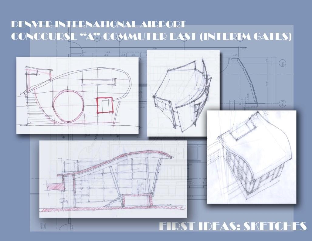
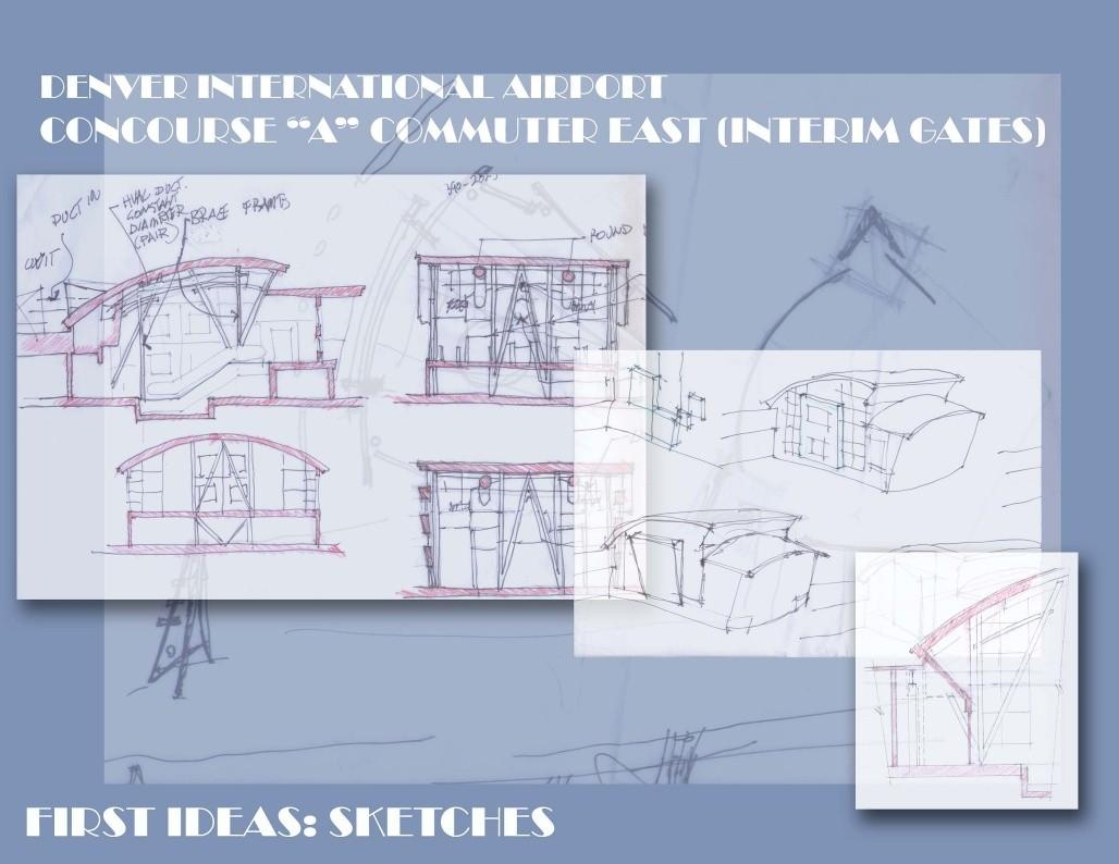
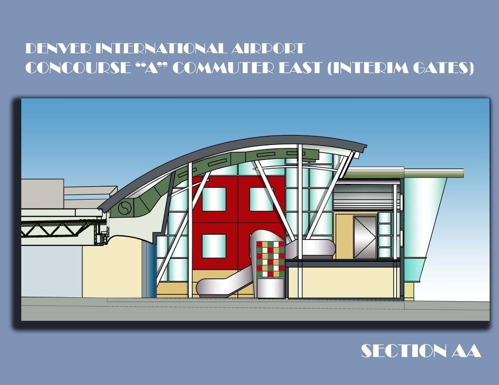
Capitalizing on the upward flow pattern of passengers resulting in a curved shell roof over the vertical circulation area.
A curved barrel-vault at right angle to the ‘main-roof’ keys off the passenger flow to the loading bridges and recalls the classic imagery of barrel vaulted hangers and terminals reminiscent of early aviation design.
The character of the light and airy space is further augmented by the organic ‘V’ shaped supports at each side of the facility and the ‘K’ bracing in the interior. The roof forms are achieved thorough the use of rolled steel members and a long-span cellular deck system expressly designed for curved roof applications.

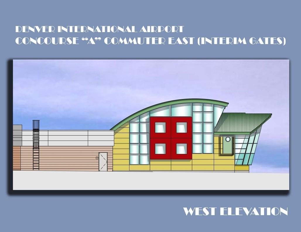
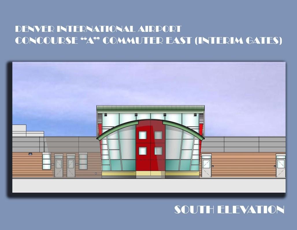
The building exerts its own personality with the dynamic and bold use of color. Bold shapes are expressed, not only in the roof, but also in plan and elevation, the upper circulation area is fronted by a sloped and curved exterior curtain-wall system. The sides incorporate a ‘solid, square element’ with square window punched in. Flanked by expense of glazing, this element appears to float.
The design presents innumerable technical challenges that demand a thoughtful and sensitive approach to system integration. Such issues include:
The existing commuter facility was designed as a temporary structure sitting directly on the existing 17” thick concrete apron. The structural engineers determined that this glass and steel pavilion needed a firmer foundation – so for this project the apron would be cut and piers and grade beam utilized.
The internal sprinkler system and an external deluge system are to be ‘fed’ by an 8” sprinkler main running several hundred feet from the main concourse to the addition. This sprinkler line could not be run on the roof or in the ceiling plenum, leaving the only option for it to be hung below the ceiling. The designer’s response was to run the line in the middle of the ceiling and hide it with decorative perforated metal shapes.
The unique nature of the roof design is incompatible with mounting major HVAC equipment on it. The solution was to ‘float’ the new mechanical unit over the roof of the existing waiting area on four existing columns below. All ductwork enters the facility through backside of the curved roof form. The unit is thusly hidden by the curved roof and the existing parapets.
The curtain wall system as specified on the project requires horizontal support due to wind loads. Instead of creating a new structure, the support is simply picked up by the ‘V’ columns supports wherever they cross the vertical curtain wall mullions.
The character of the light and airy space is further augmented by the organic ‘V’ shaped supports at each side of the facility and the ‘K’ bracing in the interior. The roof forms are achieved thorough the use of rolled steel members and a long-span cellular deck system expressly designed for curved roof applications.
The exterior building envelope is a mixture of metal panels and curtain wall glazing. For the sake of context, the existing metal panels are matched on the addition as well as the bluegreen glass. The building exerts its own personality with the dynamic and bold use of color. Bold shapes are expressed, not only in the roof, but also in plan and elevation, the upper circulation area is fronted by a sloped and curved exterior curtain-wall system. The sides incorporate a ‘solid, square element’ with square window punched in. Flanked by expense of glazing, this element appears to float.
This design presents innumerable technical challenges that demand a thoughtful and sensitive approach to system integration. Such issues include:
The existing commuter facility was designed as a temporary structure sitting directly on the existing 17” thick concrete apron. The structural engineers determined that this glass and steel pavilion needed a firmer foundation – so for this project the apron would be cut and piers and grade beam utilized.
The internal sprinkler system and an external deluge system are to be ‘fed’ by an 8” sprinkler main running several hundred feet from the main concourse to the addition. This sprinkler line could not be run on the roof or in the ceiling plenum, leaving the only option for it to be hung below the ceiling. The designer’s response was to run the line in the middle of the ceiling and hide it
The unique nature of the roof design is incompatible with mounting major HVAC equipment on it. The solution was to ‘float’ the new mechanical unit over the roof of the existing waiting area on four existing columns below. All ductwork enters the facility through backside of the curved roof form. The unit is thusly hidden by the curved roof and the existing parapets.
The curtain wall system as specified on the project requires horizontal support due to wind loads. Instead of creating a new structure, the support is simply picked up by the ‘V’ columns supports wherever they cross the vertical curtain wall mullions.