


MARCO IMPERADORI MEDINA CARMEN DIEZ CORRADO PECORA MARIA GRAZIA FOLLI SCHOOL OF ARCHITECTURE URBAN PLANNING CONSTRUCTION ENGINEERING ARCHITECTURE A.Y. 2021/2022 988206 YING-HSIU LIN 987567 VARSHINI MYSORE SURESH990635 ALALE SARABADANI991524 SEZIM SYIDALIEVA987623 AURELIEN LEROUGE989797 JUAN DAVID GARCIA FLOREZ ROYAL SKYLINE


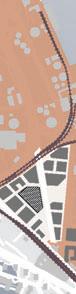


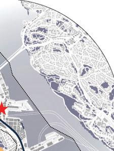
OF THE CASE STUDY Historical Analysis STOCKHOLMNORRMALMÖSTERMALMROYAL SEAPORT “SITE LOCATION” HERSERUD LIDINGÖ y 1737 Hedvig Eleonora Church 1788 Royal Drama Theatre 1889 Östermalmstorg 1903 Oscar s Church 2010 Swedish Museum of Performing Arts r 2011 The Scandic V ctoria Tower 2020 Sthlm 01 Tower / Sauerbruch Hutton 1600 STOCKHOLM CITY PLAN URBAN DEVELOPMENT METHOD LEGEND Urban Development Area Transformation Area for proposed transformation to mixed use with homes, businesses, services, streets, parks, cultur and sport facilities. The transformation can involve ent re or part h g d Urban Development Area Addition Mixed- wh xt iv additi development is proposed. The area may gain new homes, services, businesses, streets, parks, cultur and sport facilities. The area may include places h or structura hanges are proposed Strategic Connections Connections that are strategically important to attain the goal of a cohesive city Connections can be made by developing the cityscapes with buildings green corridors, activity areas and streets. Urban Corridors Over- ide stree s n he local road netwo k and motorways with side areas that can be transformed into bustling urban environments in the short or ong term. City Development Area Ecological Corridor FUTURE COMMUNICATIONS A Rail or Road development agreed or in process Rail or Road development in negotiation New Main line New Metro Station LILLA ESSINGEN MARIEBERG FREDHALL KRISTENBURG STADSHAGEN LADUGARDSGARDET VASASTADEN Högskolan OSTERMALM ROYAL SEAPORT LIDINGÖ NORTH DJURGARDEN SÖDERMALM GAMLA STAN DJURGARDEN KUNGSHOLMEN 0.20.51 km 0 Stockholm City Map 100250 500 m 0 Section SUSTAINABILITY GREEEN AREAS TRANSPORTATION HISTORY & CULTURE RESEARCH & DEVELOPMENT CONNECTION
KNOWLEDGE
STOCKHOLM Proposal of Function and Activities
THE CITY
Role of the Tower In Stockholm
OVERVIEW OF
CONCEPT OF
The
KNOWLEDGE OF THE CASE STUDY
The Role of the


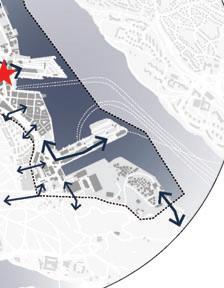


100200 400 m 0 Masterplan Map GASVERKET HJORTHAGEN SÖDRA VÄRTAN PORT & CITY Preservation, Public Sectors of the Area, Old/New Interaction Mid-rise residence, Small-scale Services, the Ring of Greenery Connection, Visual Entry, Tourism, Terminal Support, High-Rise Buildings Up to 600,000 sqm Commercial Space Starting 2022 GASKLOCKAB TOWER (90 meter height, In Construction) Herzog & de Meuron The site locates in Valparaiso (Port & City District) and aimed to link the northern and southern part of the masterplan. VÄRTATERMINALEN FERRY TERMINAL C.F. Møller Architects NASDAQ STOCKHOLM Stock Exchange Centre MAGASIN I, II, III, 9 Modern Art&Design Museum PROJECT AREA Team Anomaly UNICORN Powerful Startups over $10 billion Value FINTECH Financial Technology NOBEL MUSEUM The basic of Innovation RESEARCH KTH Royal Institute of Technology INNOVATION Misson-Oriented Innovation Method VINNOVA Sweden’s Innovation Agency CIRCULATION ECONOMY Instead of Linear Economy Spotify Mojang Studios iZettle King Klarna ECOLOGICAL LINKAGE ACTIVITIES NODES FLOWS & CONNECTION HOTSPOTS & TRANSPORTATION 2 3 4 6 southern part o the Team Anoma y 1 GASVERKET Mid-rise Residence High Density, Open Space 2 HJORTHAGEN Mid-rise Residence Low Density 3 INDUSTRY&OFFICE Of ce Complex Near the Site Area 4 PORT Port Facilities & Terminal Supportive Infrastructure 5 SÖDRA VÄRTAN Mid-rise Commerce District High Desity, Limited Open Space 6 HERSERUD Low-rise Houses Low Density THE STOCKHOLM ROYAL SEAPORT A brown eld project launched in 2000
OF THE PROJECT
Role of the Tower In Royal Seaport
Density & Building Height Keywords Cloud Kista Science Tower Tallest building in Stockholm. Second tallest of Sweden. floors 30 year 2003 Norra Tornen (in English, Northern Towers) A pair of high-rise apartment buildings Tallest residential building of Stockholm. floors 38 year 2018 The Scandic Victoria Tower is a skyscraper HOTEL floors 32 year 2011 Kista Torn floors 40 year 2015 Sthlm 01 floors 27 year 2020 Royal Seaport Tower Height 162 oors 34 year 2025 Factory Stockholm Exergi AB Height 120 (pipe)
CONCEPT
The
Masterplan
Tower
Stockholm CONNECTIONS AND AXIS OSTERMALM A ALM T ST RMMATERM ROYAL SEAPORT LIDINGÖ LID Ö D NGÖ NG N L liga ga a l NORTH DJURGARDEN DE lig Norra Djurgården Green Area EN TH T AG THAG H HA HAGAGE Green Area Park Park Green Area Greve von Essens väg Green Area Site Location Ferry Terminal Royal Djurgården South wind Bestsun orientation Stockholm University Kungliga nationalstadsparken
OF GREEN AREA
greenery near by 0.20.51 km 0 Axis and Orientation 40100 200 m 0 Urban Elevation
in
CONNECTION
As a purpose we linked our project with other
Proposal


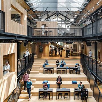
The functionality concept comes from the innovation agency in Sweden, VINNOVA. The agency developes innovative projects and provides 100+ fellowships and scholarships to worldwide candidates. It is also a local department locates in Stockholm. The potential connection between the KTH university and VINNOVA is also a reason for the setting of functionality.
Rooftop Restaurant
Third Zone: Short Stay
Buffer Zone: Mechanical
Second Zone: Coworking
Buffer Zone: Garden
First Zone: Coworking
Buffer Zone: Library


Podium: Cinema Outdoor Courtyard


Seminars Meetings Hostel Restaurant


Canopy: Interchagable
Podium: Roof passage
Podium: Food & Retail


Library Co-working

SPACES TYPOLOGY
Buffer Zones: These spaces come between the two functions of below and above and work as a joint between them. 23F-31F Hostel rooms: 9 oors - Shared social space - Shower room - Bathrooms - Shared kitchen 32F-33F 22F 11-12F 2-3F - Book shelves, Printing service - Meeting rooms, Reading area Värtatermina en Ferry & Cruise Terminal 4 Million Annual Passenger Port, Berth Depth approx.15M Waterfront stand Tramline Planning Road Tramline Waiting Booth Existing Job Agency Waterfront Plaza (new axis) Access Control (Elevator): Public Panoramic x2 Hotel Service x2 Technical&Cargo x1 Hotel Customer x4 Coworking Of ce x2 Coworking User x2 13-21F For Of ce/Long-term Users: 9 oors - Reception/ Postal services - Meeting rooms, Calling rooms - Registered of ce - Makerspace, Seminar stairs 4-11F For Public users: 8 oors 1 1 3 3 3 4 4 4 6 5 6 7 5 7 2 2 X
FUNCTIONALITY
of function and activities ACCESS CONTROL
DESIGN PROCESS PROCESS
Concept Diagram: How to Arrive the Shape&Volume (architectural)
Concept Diagram: How to Arrive the Shape&Volume (architectural)
Future Fabric (Understand the site)
(Concerntration)
(Stretch the volume)
DESIGN STRATEGY
Concept Diagram: The things that are considered for the design and the shape The that are considered for the and the
URBAN FACADE URBAN
Detail of the Podium design
Detail of the Podium


Connection from the Park Future Connection Industrial Offices The Canopy The Piazza Residential Area Access to the roof Main Entrance Main Courtyard Existing Building Furry Termina S N Center E W 162 m
Connections Panoramic View
Urban
Clear
Ground Floor
Urban Connection
Context Axis
to
Sun Analysis Vertical connection Height Accessibility Green Area Podium Pubblic Spaces Wind Analysis
the
(Orientation) Connection
the seaport (Facade & Landscape)


Pedestrian Brridge g Reeta t il Re R tail Retail Park Tram Waterfront Park Greenery Buffer Po P rt/ / Be B rth Hi H gh g way Interchangge Terminal a Coourtyarrd Courtyar a d 4 5 2 1 1 6 6 7 9 A B Podium Block H ghway Height& Symbo g Street Facade Port View Ground Connection Visua Connection & New Axis ardCouurtyar Intercchangngable A ea Area Tower Canopy 1 1 1 1 7 7 7 7 8 8 8 8 9 9 10 9 9 2 2 2 2 3 3 3 3 4 4 4 5 4 5 5 5 6 6 6 6 Värtaterminalen Ferry & Cruise Terminal with rooftop garden open to public Värtaterminalen Ferry & Cruise Terminal with rooftop garden open to public Commercial area Industrial Complex The pipe as height reference: 120m Connection to the industrial area Residential Area Tram way stop Parking Inner courtyard Highway 277/ E20 Leads to donwtown and Marieberg New Connection from the future master plan Office Complex Connected to the project by ground passage (under the bridge) Existing building which is preserved in the design aswell Park Finlandsparken Park Finlandsparken and its connect on Rebuilt Pedestrian Bridge (existing location) Two buildings in the future plan are eliminated Existing pool (water area) Added piazza as a joint with harbour CURRENT SITUATION Actual situation of the site with sourrandings Actual situation of the site with URBAN SECTIONS How the building is connected with the context How the is connected with the context DESIGN STRATEGY
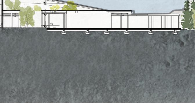
the podium For the 50100 250 m 0 Satellite Plan (Status quo) 50100 250 m 0 Project Masterplan 3060 150 m 0 Urban Section A 3060 150 m 0 Urban Section B
For


FERRY TERMINAL HARBOUR COURT YARD CANOPY ACCESS ACCESS PIAZZA BUILDINGEXISTING TRAM WAY TRAM WAY HIGHWAY GREENERY GREENERY HIGHWAY OVERALL VIEW view of the building from the city of Stockholm view of the from the of Stockholm GROUND FLOOR PLAN main plan of the podium and the towei- connection to the context main of the and the towei- connection to the context 1020 50 m 0 Ground Floor Plan Scale: 1 / 1000

Canopy

From
Rooftop
Handrail
Cultural
Outdoor
Operational
Canopy
Small
Reception of
Tower
Interchangable
Climbing
Inner
Comercial
Urban
Cinema
Lobby
Waiting area
walls
Room
courtyard Bar
access
Food Court
area
Main Hall
Commercial
Coffee shop
Scale shops
Sitting
Area
Shops
Walking area
View
the
the Podium
the park to
port by means of
well
the
to keep
greenery as
funitures, instead of handrails at
edge,
passengers safe
Lobby
Super market
DESIGN exploded isometric of the podium with two stories isometric of the with two stories
Sitting Area PODIUM


BUILDING SECTION TRANSVERSAL
0102050 0102050
BUILDING SECTION LONGITUDINAL


1 2 4 5 6 6 7 8 9 10 11 11 13 12 3 13 14 14 15 6 6 7 7 FUNCTIONALITY - RESTAURANTProposal of function and activities of function and activities Main Entrance Green sitting area Reception Vertical access Waiting area Social Table Service area Lounge Kitchen Private Tables Sitting area Toilets Backup Main corridor Bar 1 10 2 11 3 12 4 13 5 14 6 15 7 8 9 Vertical access Bar Lounge lounge Sitting area Social table Toilets Green sitting area Main s tting area Kitchen Sitting Lounge Stairs s tting area View N.03 Vertical access and greenery View N.04 Main sitting area waiting area Private tables SCALE BAR 1:200 05102030 View N.01 Main Sitting area View N.02 Social table RESTAURANT LOWER PLAN SCALE. 1:200 RESTAURANT UPPER PLAN SCALE. 1:200
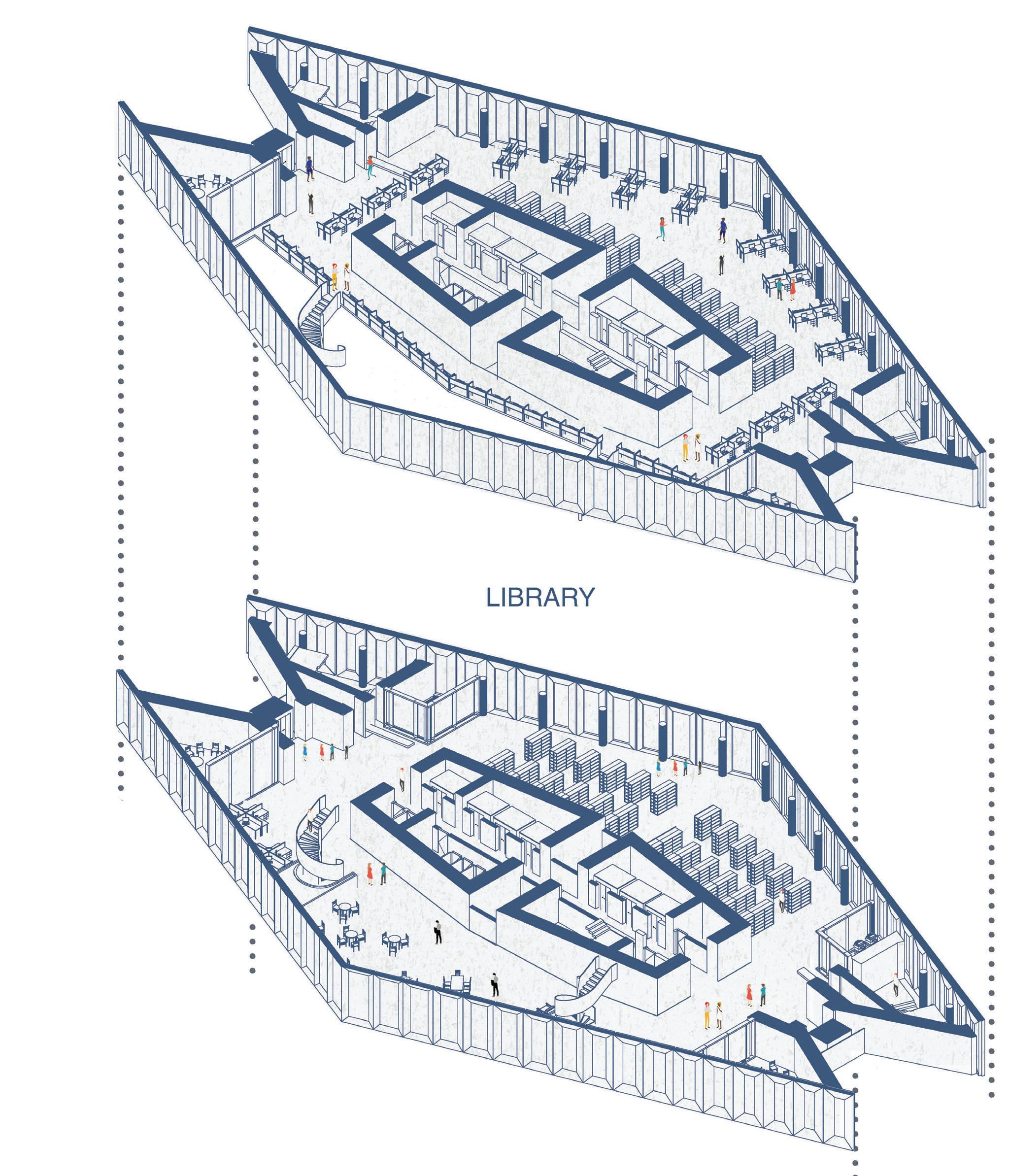


Vertical access Book shelf Study area Reception Personal study area meeting rooms Toilets Reading area Main reading area Toilets Study area Study area Stairs Treasury Private tables FUNCTIONALITY - LIBRARYProposal of function and activities of function and activities 1 10 0 2 2 3 3 5 5 4 6 7 9 8 7 3 3 8 8 11 12 12 4 6 10 View N.01 Main Studying area View N.02 Personal desks View N.03 Book Shelf View N.04 Conference room Main Corridor Toilet Reception personal study area treasury Vertical access Book shelf Reading lounge Reading area Study area Group reading area Conference area 1 10 2 11 3 12 4 5 6 7 8 9 LIBRARY LOWER PLAN SCALE. 1:200 LIBRARY UPPER PLAN SCALE. 1:200 SCALE BAR 1:200 05102030


FUNCTIONALITYCO-WORKING, HOSTEL HOSTEL Proposal of function and activities of function and activities Main Corridor TV room Toilet Reception Toilets Room type A Private working area Showers Room type B Unit type C semi private working area Private meeting rooms Conference room Study area Lounge Gaming room Laundry room 1 10 14 2 11 15 3 12 16 17 4 5 6 7 8 9 13 Toilets Bar Reception TV room Working area Loundry Private meeting room Showers Persona working area toilets Semi private working area Residential room Stairs Gaming room Conference room View N 01 Studying area View N.02 Semi private tables View N 03 Group work area View N 04 Hostel rooms 1 7 8 9 10 11 1 12 2 12 2 13 3 13 3 14 15 16 6 1 3 4 17 6 6 5 2 2 CO-WORKING PLAN SCALE. 1:200 HOSTEL PLAN SCALE. 1:200 SCALE BAR 1:200 05102030


FUNCTIONALITY VIEW Hostel - Restaurant - Library Hostel - Restaurant -


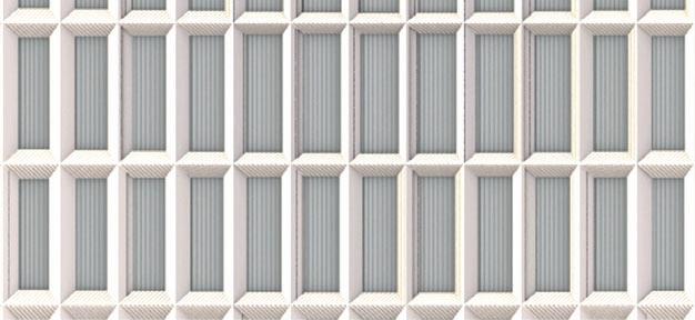


PARAMETRIC FACADE Facade- Repond to Light Interior Functions FACADE Ground Floor orientation FACADE Parametric facade due to teh function and sun analysis Due to the analysis that we could get from Ladybug and Honeybee we understood that we have different radiations for all the facades of the tower. Each facade has a different orientation according to the sun therefore has different amount of sun and light. On the other hand, because of the functions that we have for the tower, we can say we need different amount of light for each space. PARAMETRIC FACADE Grasshopper Work ow PARAMETRIC FACADE Oppennness 1 2 3 4 5 6 7 8 9 1 STEEL BEAM HEA 700 5 JOINT 2 HORIZONTAL CONNECTOR 6 THERMAL INSULATION 3 PRECAST CONCRETE PANELS 7 WINDOW FRAME 4 FIRST LAYER INSULATION 50mm 8 DOUBLE LAYER GLASS 9 STEEL BEAM HEA 360 Maximum and minimum dimeters of the oppenness Transition in the dimention of the panels of the facade PARAMETRIC FACADE Details

PARAMETRIC FACADE
Details of the facade - tower and Podium
Main S tructure Win d ows as t h e height of the floor C urtain s for controlling h e lig h t INTERIOR OF THE TOWER Details of the facade in the interior spaces


VIEWS CONNECTIONS THROUGH THE BUILDING SCHEME OF THE SLABS AND CONNECTIONS OF THE FACADE SCHEME OF THE SLABS AND DETAILS OF THE COMPOSITION AUDITORIUM WALL DETAIL PODIUM FIRST FLOOR PLAN SCALE 1:1000 DETAIL B SCALE 1:20 AUDITORIUMWALLDETAIL SCALE 1:20 AUDITORIUM DOOR DETAIL SCALE 1:20 DIAGRAMATIC SECTIONS OF PODIUM STRUCTURE 1 EXTERIOR WOODEN PANEL6 DRYWALL 5 BREATHABLE MEMBRANE 2 FIRST LAYER OF INSULATION7 28mm TIMBER BATTEN 3 SECOND LAYER OF INSULATION8 INTERIOR AUDITORIUM CLADDING 4 ACCOUSTIC DRY WALL WITH INSULATION9 AUDITORIUM SEATING 10 ACCOUSTIC DOOR 1 1 2 2 3 3 4 4 5 5 6 6 7 7 8 10 9 10.0 10.0 10.0 10.0 10.0 .0 16 23 26 PODIUM STRUCTURE PLAN SCALE 1:1000 PODIUM STRUCRUE Structural plan - details of the design PODIUM STRUCRUE Technical details - Auditorium STRUCTURAL ELEMENTS Main core - Columns - Facade Core Core Coulumns Coulumns Beams Beams Facade Slabs
SCALE
EXPLODED ISOMETRIC VIEW elements of the podium and facade in layers


SLAB PRIMARY AND SECONDARY BEAMS TOWER BUILDING PODIUM WOOD STRUCTURE PODIUM WOOD TRUSS & COLUMN CANOPY WOOD WAFFLE BEAM & COLUMN CORE CONCRETE STEEL CLT ROOF TRUSS GLU-LAM TRUSS PARAMETRIC FACADE TYPICAL STRUCTURAL PLAN SCALE 1:200 DOUBLE HEIGHT STRUCTURAL PLAN SCALE 1:200 SECONDERY BEAMS PRINCIPAL BEAMS CORE AND CONCRETE SHEAR WALLS COLUMNS FACADE CONFIGURATION OF THE CORE EXPLODED AXONOMETRIC VIEW CROSS SECTION OF STRUCTURE
PLANS Plans for the tower with structural elements
STRUCTURAL
BAR 1:200
05102030


1 2 3 4 5 6 7 8 9 10 11 12 13 14 9 15 16 18 DETAIL AT ADETAIL AT C DETAIL AT D SLAB SECTION 1:50 DETAIL AT A SCALE 1:20 DETAIL OF CLC JOINERY WITH CORE SCALE 1:20 DETAIL AT B SCALE 1:20 VIEW OF THE SLAB & FACADE 18 19 19 23 24 25 26 11 1 20 21 22 13 9 3 8 5 26 13 1 24 21 11 27 20 28 STRUCTURAL ELEMENT Section details 1 STEEL BEAM HEA 700 5 JOINT 2 HORIZONTAL CONNECTOR 6 THERMAL INSULATION 3 PRECAST CONCRETE PANELS 7 WINDOW FRAME 4 FIRST LAYER INSULATION 50mm 8 DOUBLE LAYER GLASS 9 STEEL BEAM HEA 360 10 SAFETY RAILING 12 WALL FINISHING 19 SIDE WELD L-ANGLE 15 CLADDING 22 ACCOUSTIC INSULATION 11 FINISHING BOARD 13 CLT LAYER 20 FLOORING IN WOOD 16 FALSE CIELING 23 TIMBER SCREWS 14 STEEL BEAM & CONCRETE WALL JOINT 21 IMPACT INSULATION AREA 17 FRAMEWORK 24 DUCT FOR VENTILATION & MEP 18 SELF-TAPPING SCREWS 25 BARS FOR CONNECTION 27 ALUMINIUM PROFILE 26 CONCRETE CORE 28 HORIZONTAL CONNECTOR


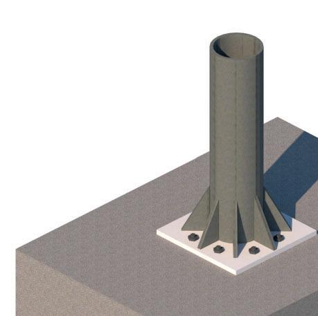


1 2 3 4 5 6 7 8 9 10 11 DETAILATD 12 13 4 5 6 7 3 2 1 DETAIL AT C -SECTION OF SLAB SCALE 1:20 VIEW OF COLUMN CONNECTION DETAIL AT D SPLINE CLT CONNECTION SCALE 1:10 1 FLOORING IN WOOD 5 PLASTERBOARD 2 IMPACT INSULATION LAYER 6 SELF-TAPPING SCREWS 3 CLT LAYER (0.175m) 7 STEEL BEAM HEA 360 4 ACCOUSTIC INSULATION 8 DUCT FOR VENTILATION 9 STEEL BEAM HEA 700 10 PROFILE FOR ROOFING 12 TIMBER SCREWS 19 SCREWS BOLDS 15 IMPACT INSULATION AREA 22 BARS FOR CONNECTION 11 FINISHING BOARD 13 SECTION OF TIMBER + TOLERANCE GAP 20 SCREWS FOR CONCRETE 16 ACCOUSTIC INSULATION 23 CONCRETE CORE 14 FLOORING IN WOOD 21 DUCT FOR VENTILATION & MEP 17 SELF-TAPPING SCREWS 18 CONNECTION PIN PLATE CONNECTION OF COLUMN WITH THE BEAMS CONNECTION OF BEAM WITH THE CORE CONNECTION OF COLUMN WITH BASE CONNECTION OF BEAM TO CORE SCALE 1:10 14 15 17 18 7 22 20 11 18 23 11 19 21 13 12 16 3 STRUCTURAL ELEMENT Section details HEA 700 HEA 360 HEA 360 CHS 406/25 CHS 406/25 FOUNDATION CONCRETE CORE HEA 700


TRUSS SECTION SCALE 1:50 DETAIL AT 1 DETAIL AT 2 1 3 6 2 4 5 8 7 DETAIL AT 1 SCALE 1:20 DETAIL AT 2 SCALE 1:20 11 12 13 10 9 1 2 3 4 5 6 7 8 9 10 11 12 13 GLASS COVERING CONCRETE CORE RAFTERS RAINWATER GUTTER RECTANGULAR SECTION PURLINS BOTTOM WOOD POST CONNECTING PLATE STEE BEAM WATERPROOF MEMBRANE PRECAST CONCRETE PANEL PRINCIPAL RAFTER STEEL COLUMN ABCDEFGH 34F +162.00 33F +157.50 32F +153.00 31F +148.50 30F +144.00 29F +139.50 4,5 4,5 4,5 4,5 4,5 4,5 TECHNICAL FLOOR TECHNICAL FLOOR TECHNICAL FLOOR BASEMENT WATER DISTRIBUTED IN THE FLOORS VERTICAL WATER DISTRIBUTION ELECTRICITY VENTILATION PLOMBING FIRE-SMOKE HOTEL ELEVATOR OFFICE ELEVATOR COWORKING ELEVATOR PANORAMIC ELEVATOR TECHNICAL ELEVATOR ROOFTOP DETAILS MEP ORIENTATION Elevator Distribution MEP ORIENTATION Vertical Shafts MEP Typical Plan ELECTRICITY VENTILATION PLOMBING FIRE-SMOKE PANORAMIC ELEVATOR VISITOR CARGO ELEVATOR PANORAMIC ELEVATOR VISITOR TECHNICAL ROOM TECHNICAL ROOM ENTRY AND RETRAIL LIBRARY GREENHOUSE TERRACE ROOFTOP RESTAURANT COWORKING UNIVERSITY COWORKING OFFICES HOSTEL
q = (G1x1,3) + (G2x1,3) + (Qx1,5)
q=
q=
Mmax:
Mmax:
Mmax: 665 kNm
Mpl: Wpl x (Fy/Mo)
Mpl: 0,007032 m3 x (275000 kN/m2 / 1,05)
Mpl:
Mpl
Mmax: 35,86 kNm
Mpl: Wpl x (Fy/Mo)
Mpl: 0,002088 m3 x (275000 kN/m2 / 1,05)
Mpl: 546,85 kNm
Mpl
q = (G1x1,3) + (G2x1,3) + (Qx1,5)
q= (3,56kN/m x1,3) + (12,23kN/m x1,3) + (12kN/m x1,5)
q= 38,54kN/m
Imax/min = I / A
Imax/min = 0,000598 m4 / 0,019458
Imax/min
=
p
p
p
ref
q = G1 + G2 + Q
q= 3,56 kN/m + 12,23 kN/m + 12,0 kN/m
q= 27,80 kN/m
Wmax
q = (G1x1,3) + (G2x1,3) + (Qx1,5)
q= (3,56kN/m x1,3) + (12,23kN/m x1,3) + (12kN/m x1,5)
q= 38,54kN/m
Imax/min = I / A
= 0,000598 m4 / 0,019458 m2 Imax/min = 0,1752
=
CHARACTERISTICS OF BEAM Beam spam: 3,7 m Competence distance: 2,3 m DEAD LOADS G1 Dead Load (structure): 1,12 kN/m HEA360 1,12 kN/m G2 Dead Load (slab): 7,04 kN/m CLT slab: 0,771kN/m2 Materials x 2,3 m 3,06kN/m2 x 2,3 m LIVE LOADS Q Live load (of ce): 6,9 kN/m Category B 3,0 kN/m2 x 4,0 m CHARACTERISTICS OF THE COLUMN Column spam: 6,75 m Area of in uence 23,2 m DEAD LOADS G1 Dead Load (structure): 3,57 kN/m HEA700 - HEA360 2,04kN/m + 1,52kN/m G2 Dead Load (slab): 12,23 kN/m CLT slab: 0,771kN/m2 Materials x 4,0 m 3,06kN/m2 x 4,0 m LIVE LOADS Q Live load (of ce): 12,0 kN/m Category B 3,0 kN/m2 x 4,0 m SECONDARY BEAM HEA360 h = 350 mm b = 300 mm tw =10,0 mm G = 112 kg/m Iy = 0,0003309 m4 Wply = 0,002088 m3 iy = 15,22x10 mm E: 200000000 kN/m2 PRINCIPAL COLUMN CHS 508/12,5 d = 508,0 mm t = 12,5 mm G = 153,1 kg/m A = 0,019458 m2 Iy = 0, 000598 m4 i = 0,1752 m Lcr = 5,40 m Fy = 223800 kN/m2 E: 200000000 kN/m2 q = G1 + G2 + Q q= 1,12 kN/m + 7,04 kN/m + 6,9 kN/m q= 15,06 kN/m Wmax / Wmin < 1 Wmax: (5/384) x q x L4 /E x Iy Wmax: (5/384) x 15,06 kN/m x 3,7 m / 200000000 kN/m2 x 0,0003309 m4 Wmax: 0,000555 Wmin: 1 /250 x L Wmin: 1/250 x 3,7 m Mmin: 0,0148 Wmax / Wmin < 1 0,000555 / 0,0148 0,04 < 1 Resistance check
= (G1x1,3) + (G2x1,3) + (Qx1,5) q= (1,12kN/m x1,3) + (7,04kN/m x1,3) + (6,9kN/m x1,5) q= 20,96 kN/m Mmax: 1/8 x q x L2 Mmax: 1/8 x 20,96 kN/m x (3,7 m)2
q
546,85
kNm Resistance check
> Mmax
kNm > 35,86
m2
= 0,1752 m2
Io / Imin = 5,40 m / 0,1752 m2 = 30,81
= x E
fy
/
= x 200000000 kN/m2
/ 223800 kN/m2
93,91
=
= / p ref = 30,81 m / 93,91 ref = 0,33
Imax/min
m2
Io
Imin = 5,40 m / 0,1752 m2 = 30,81 p = x E / fy p = x 200000000 kN/m2 / 223800 kN/m2 p = 93,91 ref = / p ref = 30,81 m / 93,91 ref = 0,33 Vmax: 5/8 x q x L Vmax: 5/8 x 20,96 kN/m x 3,7 m Vmax: 48,46 kNm Va : (Av x Fy)/ 3 x Mo Va : 0,04896 m2 x 275000 kN/m2 / 3 x 1,05 Va :5384203,65 kNm VA > Vmax 5384203,65 kNm > 48,46 kNm Resistance check = 1 + ( ref -0.2) + ref2 / 2 = 1 + 0,21(0,33 - 0,2) + 0,33 / 2 = 0,57 = 1/ + + ref2 = 1/0,57 + 0,572 + 0.332 = 1,22 Nb,rd = A * fy * / m Nb,rd = 0,019458 m2 * 223800 kN/m2 * 1,22 / 1.05 Nb,rd = 4147,33 Ned = (((1.3xG)+(1.5xQ) )x33) + Load columns x 1.3 Ned = q x 32 + 243,06 kN/m Ned = 1476,27 Nb,rd > Ned 4147,33 > 1476,27 Resistance check LOADS LOADS SECONDARY BEAMS ULS COLUMN SECONDARY BEAMS SLS 4m 2.3m 2.3m CHARACTERISTICS OF BEAM Beam spam: 11,75 m Competence distance: 4,0 m DEAD LOADS G1 Dead Load (structure): 3,57 kN/m HEA700 - HEA360 2,04kN/m + 1,52kN/m G2 Dead Load (slab): 12,23 kN/m CLT slab: 0,771kN/m2 Materials x 4,0 m 3,06kN/m2 x 4,0 m LIVE LOADS Q Live load (of ce): 12,0 kN/m Category B 3,0 kN/m2 x 4,0 m PRINCIPAL BEAM HEA700 h = 690 mm b = 300 mm tw =14,5 mm G = 204 kg/m Iy = 0.002153 m4 Wply = 0.007032 m3 iy = 28,75x10 mm E: 200000000 kN/m2
/
/ Wmin < 1 Wmax: (5/384) x q x L4 /E x Iy Wmax: (5/384) x 27,80 kN/m x 11,75 m / 200000000 kN/m2 x 0,002153 m4 Wmax: 0,016 Wmin: 1 /250 x L Wmin: 1/250 x 11,75 m Mmin: 0,047 Wmax / Wmin < 1 0,016 / 0,047 0,34 < 1 Resistance check
+ (12kN/m x1,5)
(3,56kN/m x1,3) + (12,23kN/m x1,3)
38,54kN/m
1/8 x q x L2
1/8 x 38,54 kN/m x (11,75 m)2
1841,71 kNm
> Mmax 1841,71 kNm > 665 kNm Resistance check Vmax: 5/8 x q x L Vmax: 5/8 x 12,23kN/m x 11,75 m Vmax: 283,01 kNm Va : (Av x Fy)/ 3 x Mo Va : 0,0117m x 275000 kN/m2 / 3 x 1,05 Va :1769,16 kNm VA > Vmax 1769,16 kNm
283,01 kNm Resistance check LOADS PRINCIPAL BEAMS ULS PRINCIPAL BEAMS SLS 4.0m4.0m 11.75m CALCULATIONS Details
>
