PARAMETRIC SOFTWARES
1
Anahita Ghatage
F.Y. Digital Architecture , B.N.C.A
DA1905_2019-20
Tutors : Ripple Patel | Mugdha Gandhi
01 Modelling
1.1 Furniture Design
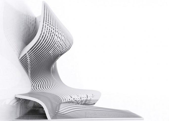
1.2 Lofted Geomteries
1.3 High Rise Structures
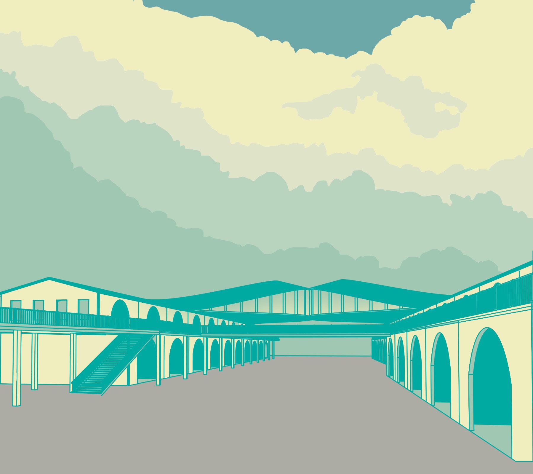
1.4 Coal Drops Yard
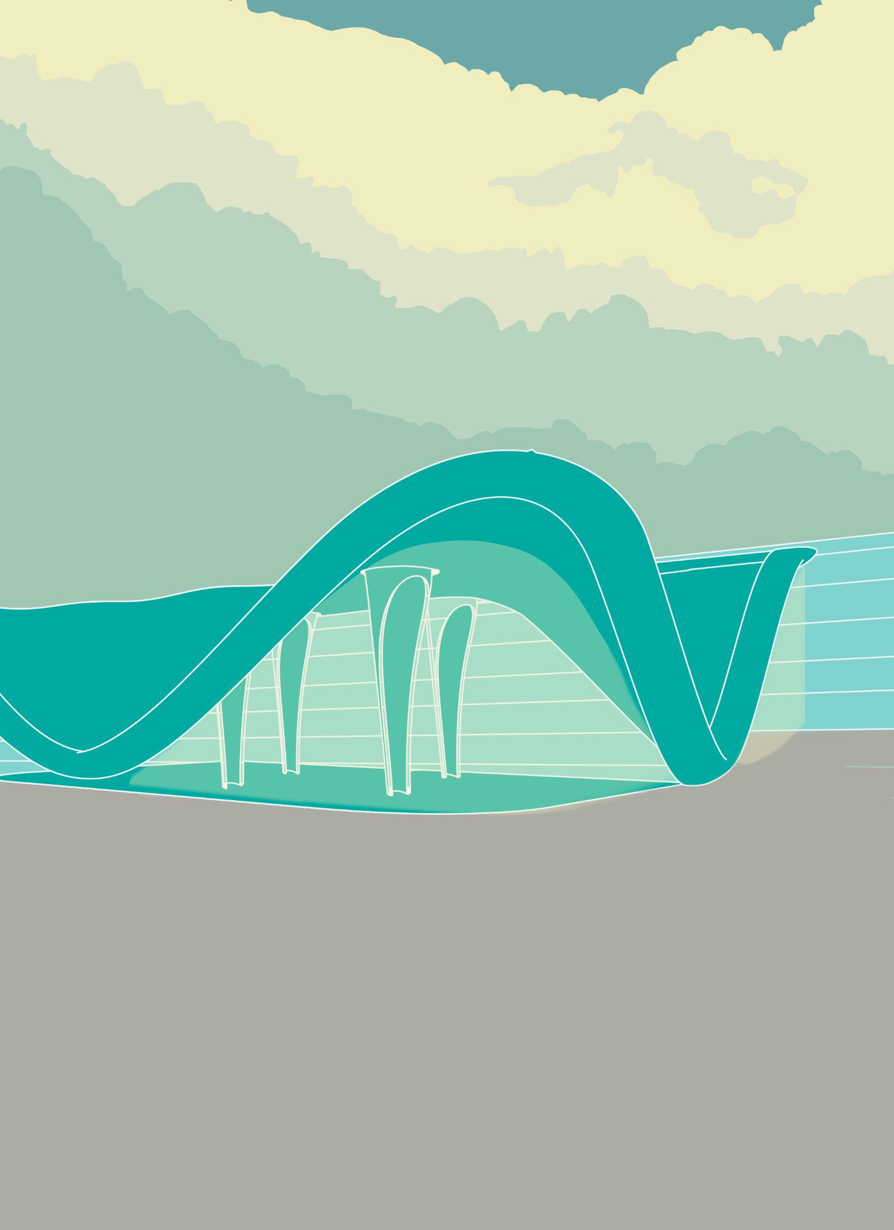
1.5 Serpentine Sackler Gallery
02 Geometry
2.1 Parametric Star
2.2 Rotating Panels
2.3 Wall Panel
2.4 Parametric Louvers
2.5 Rotating Cylinders
2.6 Fractals - Koch Snowflake
2.7 Mathematical Surfaces
2.8 Recreating Felix Candela’s Shell Structures
03 Manipulation &Transformation
3.1 Single and Multiple Attractor Points
3.2 Attractor Curves
3.3 SDU Facade
About the Author
Anahita Ghatage
Architect | Designer
Student of Digital Architecture
Abstract
Department of Digital Architecture Semester 1_2019-20
This book shall contain basic exercises in Rhino and Grasshopper as an Introduction to 3d modelling and parametric design. The final chapter about the Natural Phenomenon shall speak about logic based diagrams of The Glass Sponge and a few exercises that could be explored based on this logic.
3.4 Hybrid Facade
04 Natural Phenomenon
4.1 Anatomy of the Hexactinellid Deep Sea Sponge
4.2 Structural & Component Logic
4.3 Relationship Between Components
4.4 Exploring Exoskeletons- WeaverBird
4.5 Exploring Mesh and Weave
2 3
CONTENT
Chapter 01: Modelling
4 5
Creating a Grid according to Anthropometry and Ergonomics
RHINO FURNITURE DESIGN
The Chair has been designed using CURVES FROM TWO VIEWS. This allows us to achieve this type of geometry.
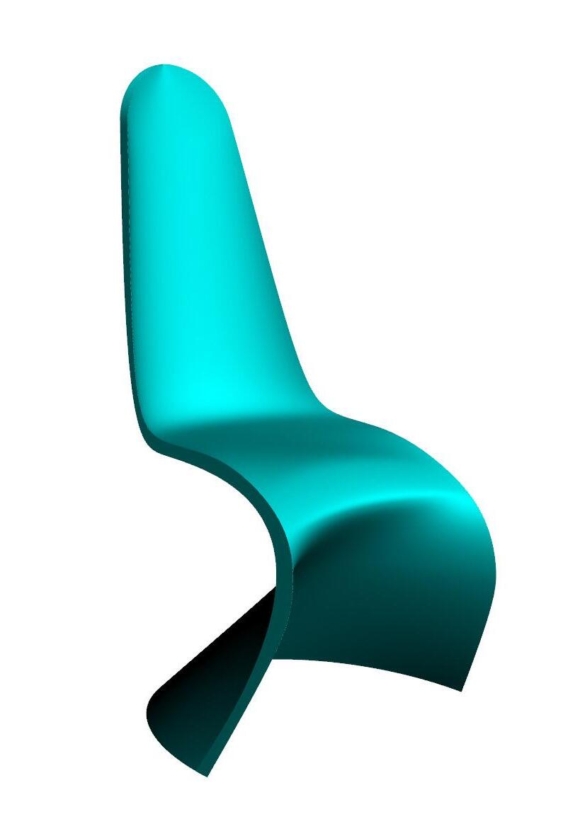
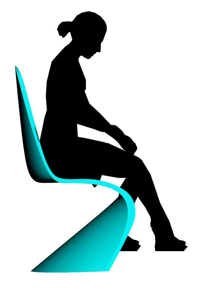
Creating two Curves for the Front and Side Using CURVE FROM TWO VIEWS to achieve the desired item
Creating the Chair using Loft (Selecting curves to create loft)
6 7 INTRODUCTION TO
LOFTED GEOMETRIES
1. Lofted Geometries from 2 curves
2. Lofted Geometries from 3 curves
3. Lofted Geometries from 4 curves
Create Base Curve
Create Secondary Curves for Contours
Create Secondary Curves for Loft & Contours
8 9 INTRODUCTION TO
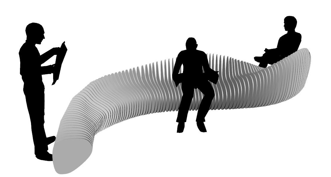
RHINO
PARAMETRIC BENCH
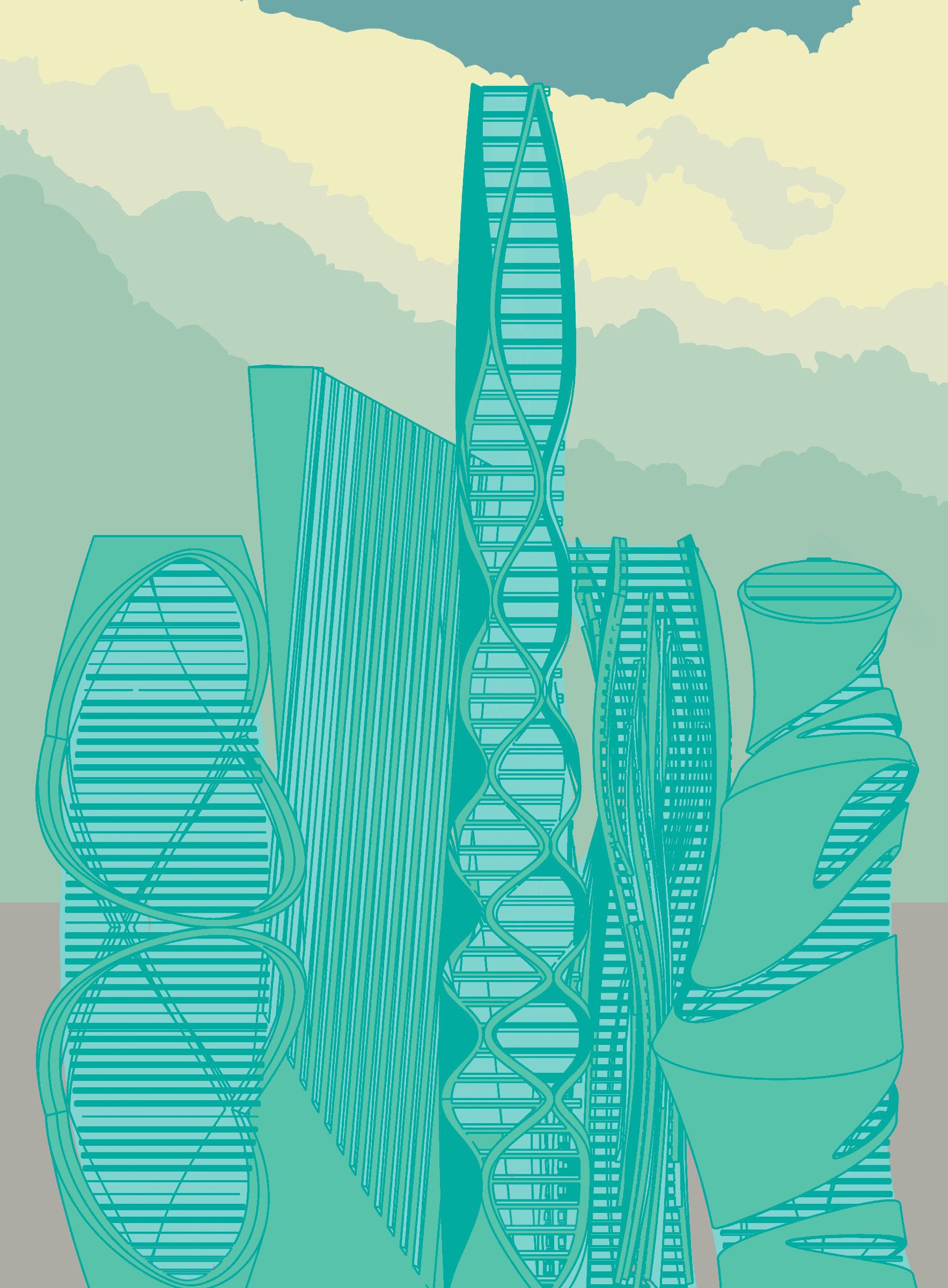
11 01 02 03 04 05 high rise structures Create and Apply UV Curves
12 13
Process Steps Involved in Modelling the Coal Drops Yard
COAL DROPS YARD
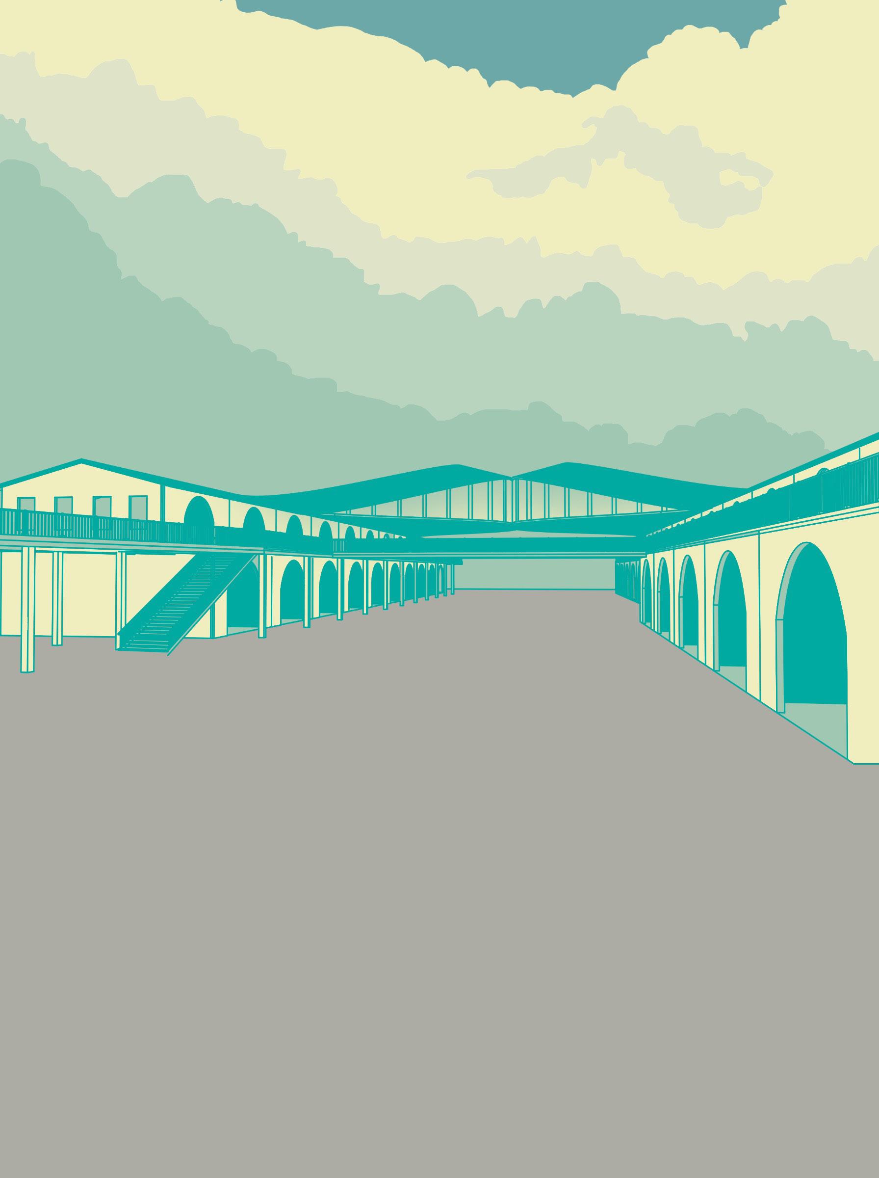
SERPENTINE SACKLER GALLERY PARK
Process Steps Involved
14 15
in Modelling of the Column of Serpentine Sackler Gallery Park
Chapter 02: Geometry
16 17
PARAMETRIC STAR
GRASSHOPPER BASICS
Grasshopper is a visual programming language and environment developed by David Rutten at Robert McNeel & Associates, that runs within the Rhinoceros 3D computer-aided design (CAD) application. Programs are created by dragging components onto a canvas.
1. Create Circle
2. Divide Curve
3. Select Alternate Points (Dispatch)
4. Move Selected Points (Vector and Amplitude)
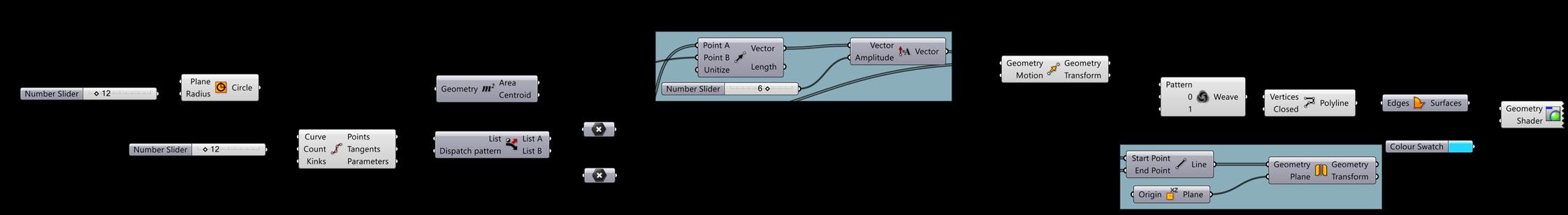
5. Weave
Achieve Different Number of Divisions by Changing Number Slider
Achieve Larger/ Smaller Geometry by Changing Radius of Circle
Use Custom Preview Apply Colour Swatch
18 19 01. Coding and Programming for Architects- ArchDaily 02. Architecture and AI 03. Generative Design Using Algorithmic Modelling 04. Use of Computation Design in Architecture 01 03 02 04
INTRODUCTION TO GRASSHOPPER
RotaTING Panels
Create Rectangle Offset and Range
Rotate 3D
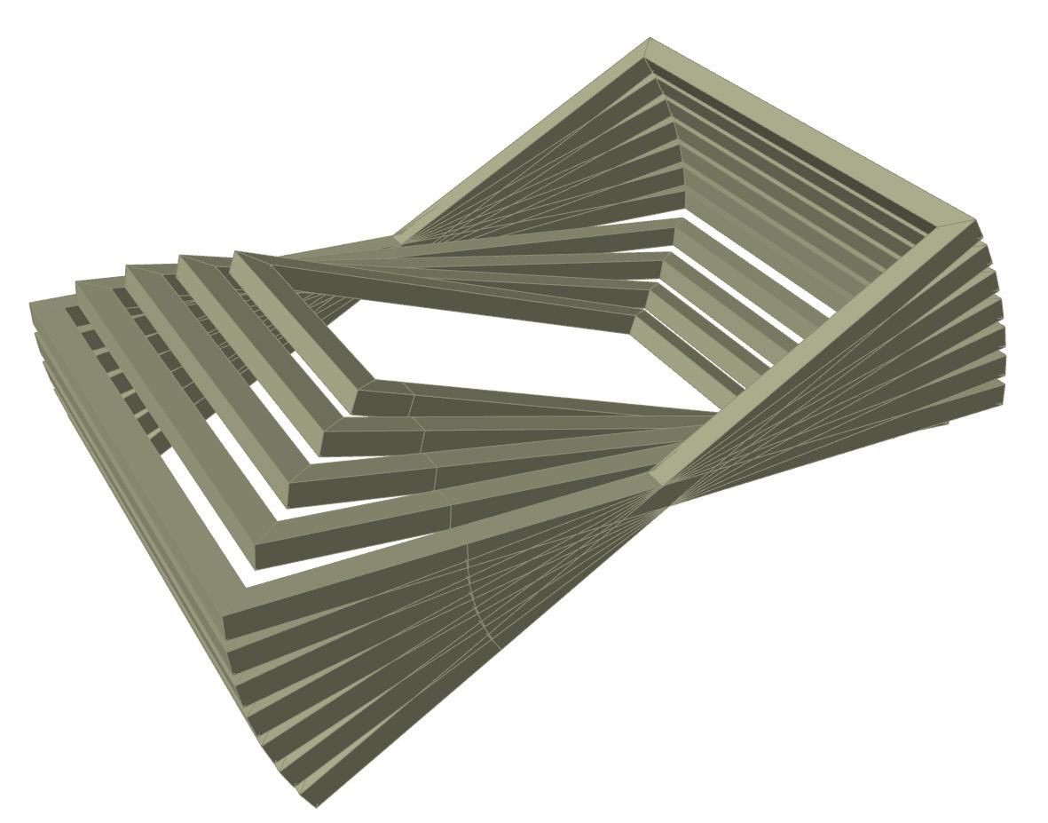
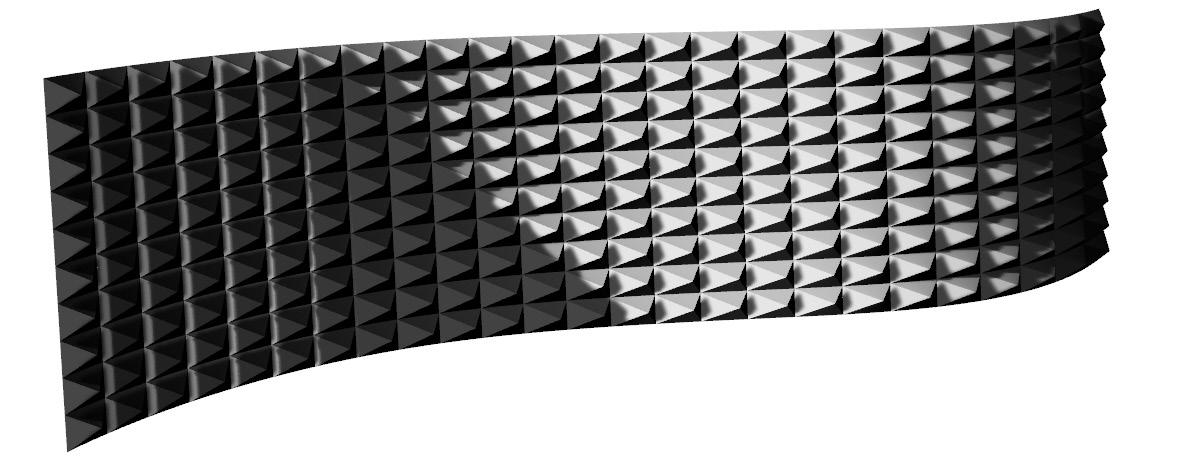
WALL PANEL
Create Subdivisions Divide Domain2 Isotrim

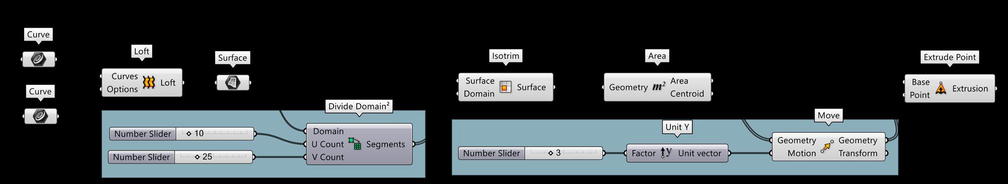
Create Thickness Offset Curve Loft Extrude
Extract Centroid and Extrude Point
20 21
Create Loft from 2 Curves
PARAMETRIC LOUVERS
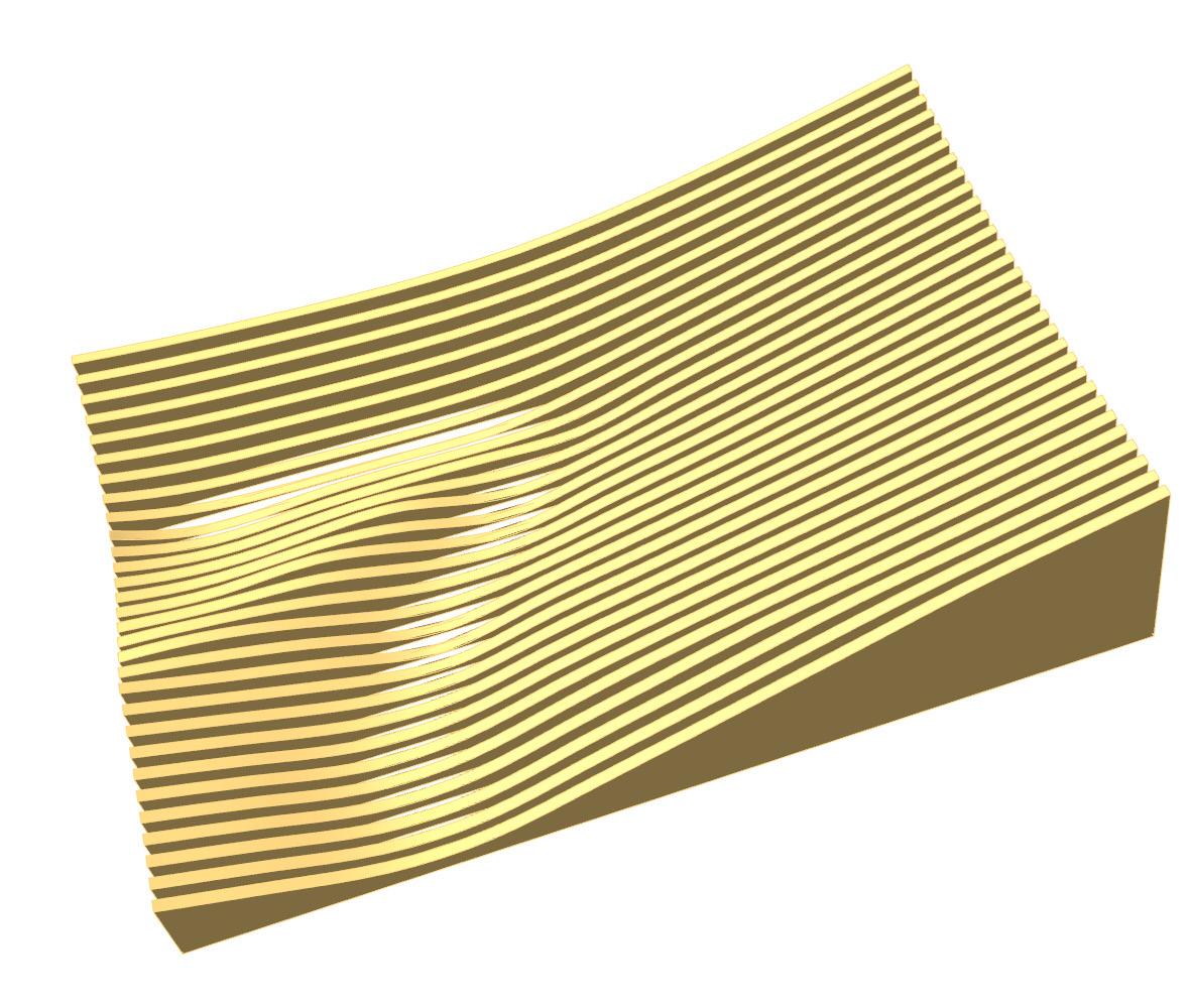
Create Rectangle Contour
Divide Curve
Create Curve Closest Point for Attractor
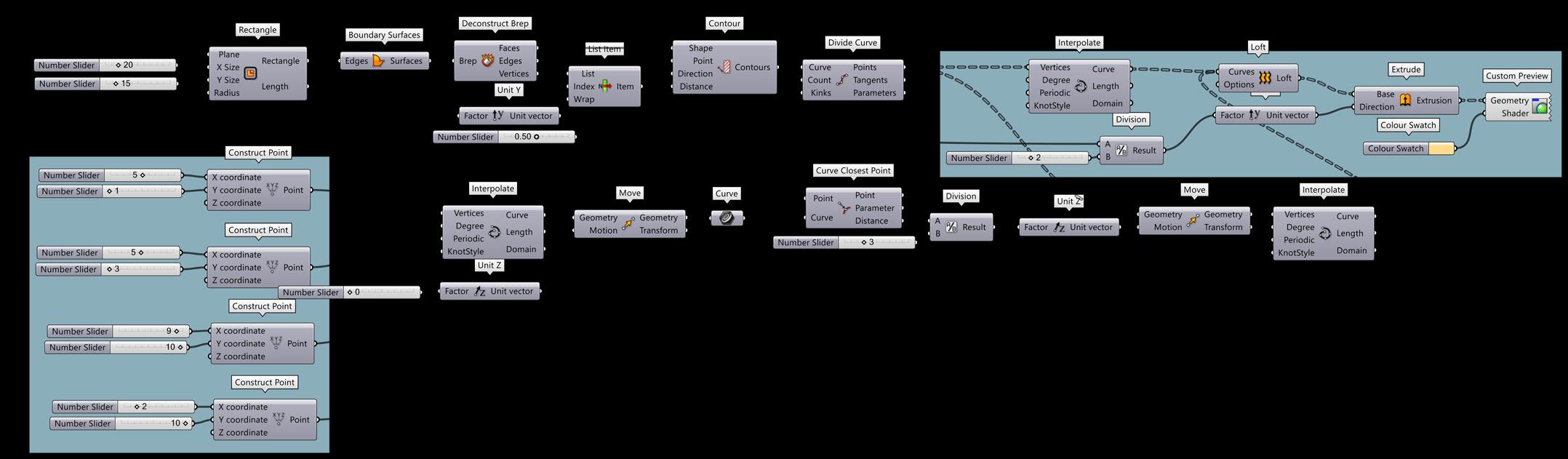
Loft
Create Extrusion
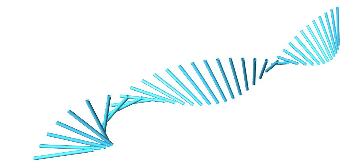
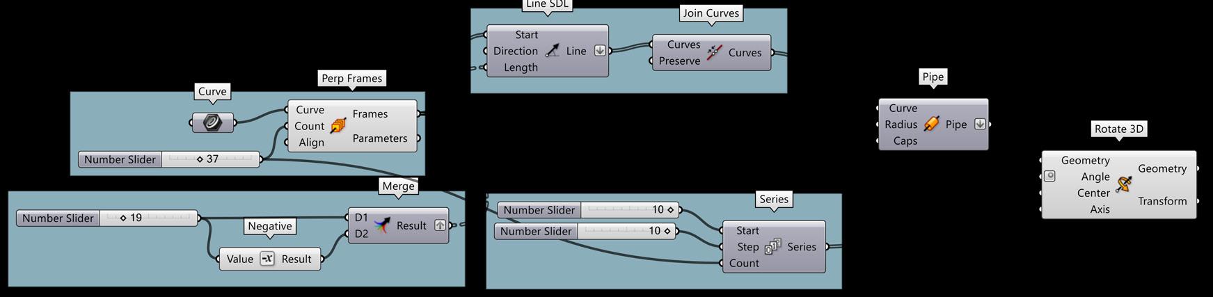
ROTATED CYLINDERS
Create Curve
Perpendicular Frames
Line SDL and Pipe Rotate
22 23
FRACTALS THE KOCH SNOWFLAKE
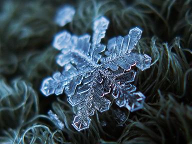
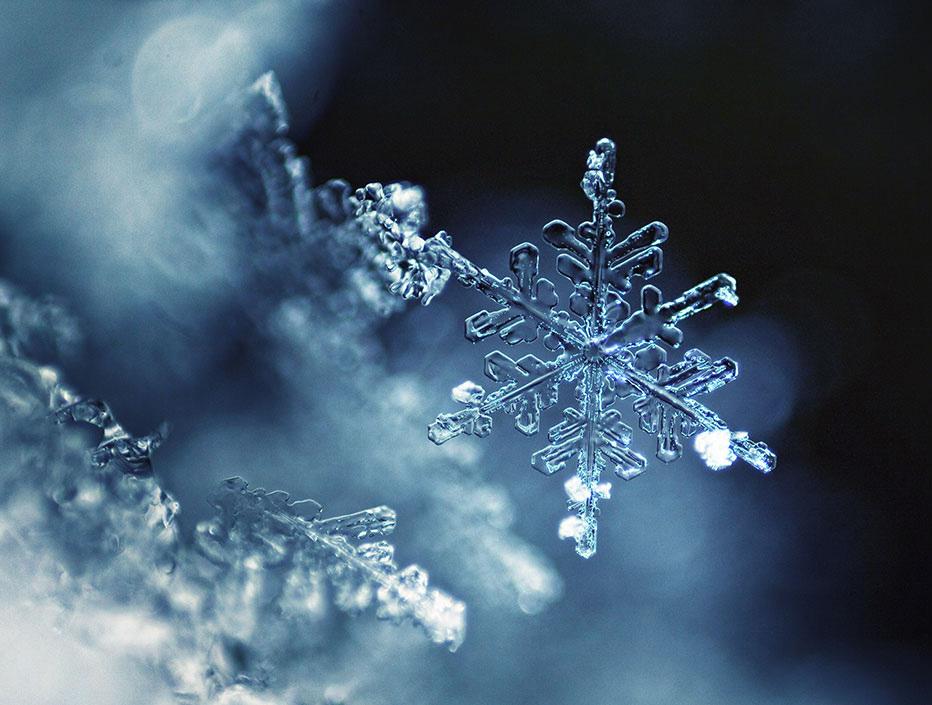
In mathematics, a fractal is a subset of a Euclidean space for which the Hausdorff dimension strictly exceeds the topological dimension. Fractals exhibit similar patterns at increasingly small scales called self similarity, also known as expanding symmetry or unfolding symmetry. Fractal geometry lies within the mathematical branch of topology.
The feature of “self-similarity”, for instance, is easily understood by analogy to zooming in with a lens or other device that zooms in on digital images to uncover finer, previously invisible, new structure. If this is done on fractals, however, no new detail appears; nothing changes and the same pattern repeats over and over, or for some fractals, nearly the same pattern reappears over and over.
24 25
The Koch snowflake (also known as the Koch curve, Koch star, or Koch island) is a mathematical curve and one of the earliest fractals to have been described. It is based on the Koch curve, which appeared in a 1904 paper titled “On a Continuous Curve Without Tangents, Constructible from Elementary Geometry” by the Swedish mathematician Helge von Koch.
Base Geometry Derivation Logic
1. Polygon 2. 3 Segments (Triangle)
3. Divide Segments 4. Perpendicular Frame
5. Deconstruct Plane & Move
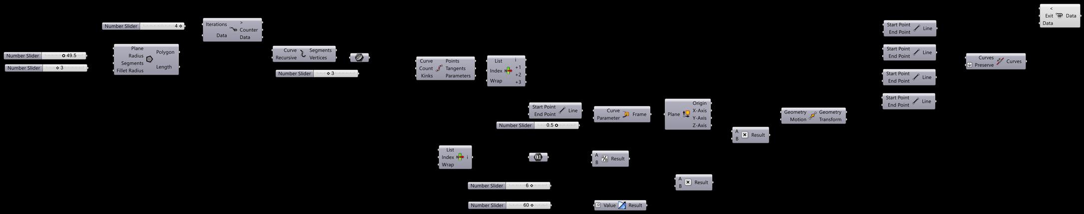
6. Join Curves 7. Anemone (Fast Loop Start/End)
Growth Logic at Iteration 01
Equilateral Triangles with each angle as 60 degrees
Image Source: Internet
Growth Logic at Iteration 02
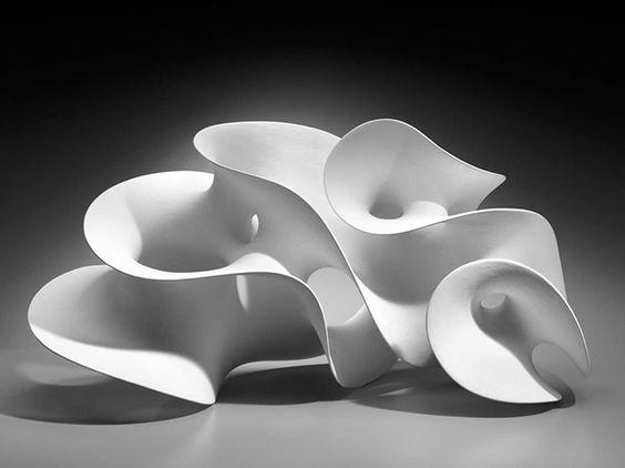
MATHEMATICAL SURFACES
Growth Logic at Iteration 03
Growth Logic at Iteration 04
Reference for Definition: Parametric3d
Source: Internet
In mathematics, a minimal surface is a surface that locally minimizes its area. This is equivalent to having zero mean curvature (see definitions below).
The term “minimal surface” is used because these surfaces originally arose as surfaces that minimized total surface area subject to some constraint. Physical models of area-minimizing minimal surfaces can be made by dipping a wire frame into a soap solution, forming a
soap film, which is a minimal surface whose boundary is the wire frame. However, the term is used for more general surfaces that may self-intersect or do not have constraints.
For a given constraint there may also exist several minimal surfaces with different areas the standard definitions only relate to a local optimum, not a global optimum.
26 27 Fractal Iterations
Demonstration of Growth Logic around Base Geometry
Cartesian Coordinate System
Polar/Spherical Coordinate System
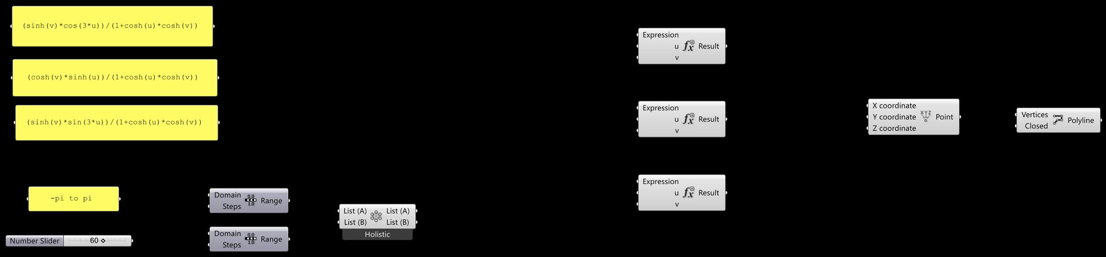
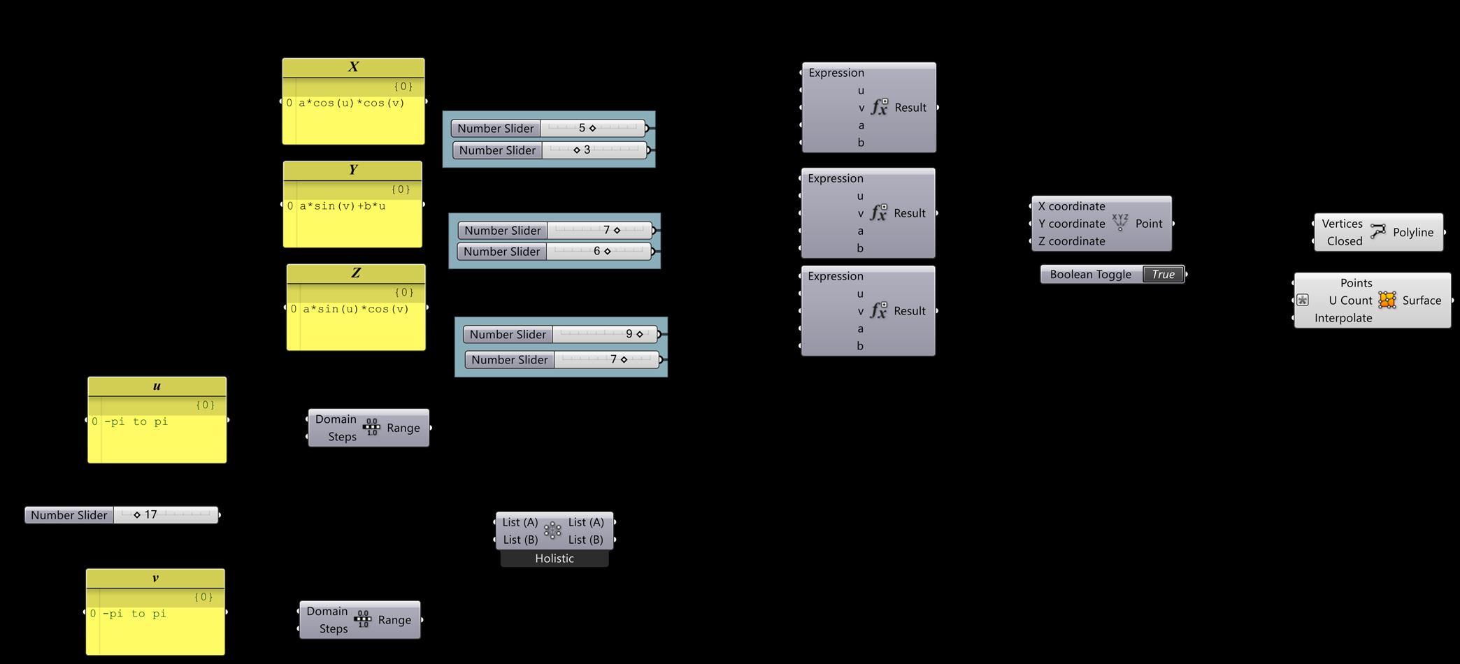
Grasshopper Definition
SPIRAL
Mathematical Expression Used For Spiral: (sinh(v)*cos(3*u))/(1+cosh(u)*cosh(v)) (cosh(v)*sinh(u))/(1+cosh(u)*cosh(v)) (sinh(v)*sin(3*u))/(1+cosh(u)*cosh(v))
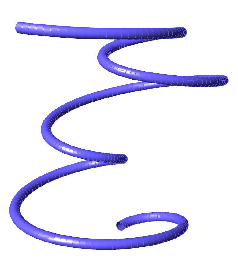
Domain : -pi to pi
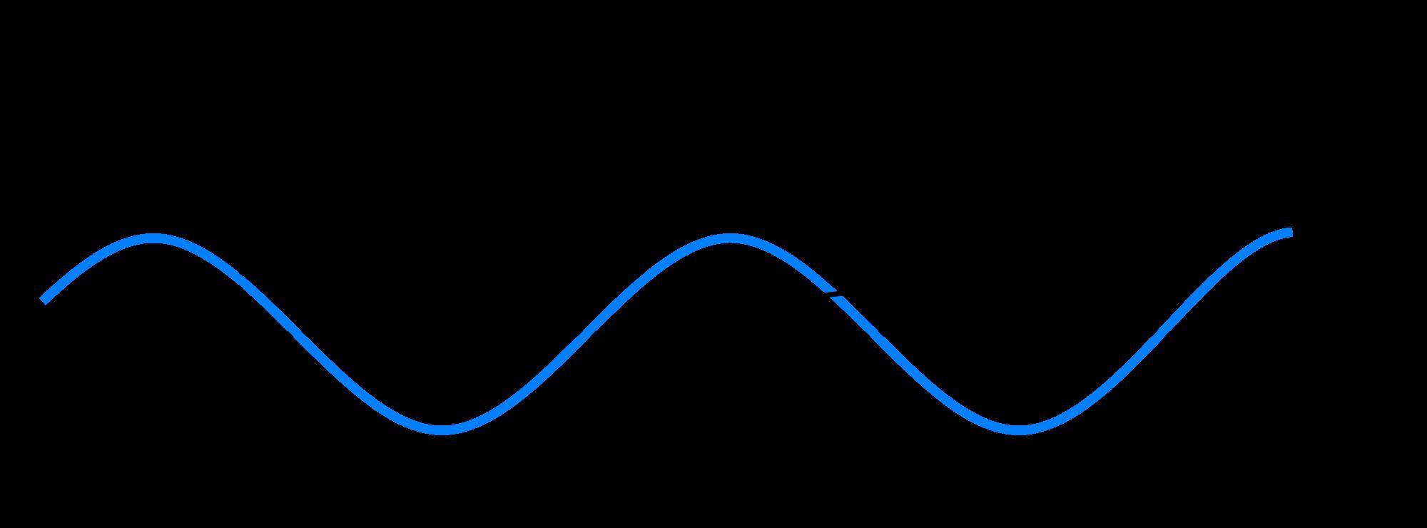
Sine curve
Mathematical Expression Used For Sine Curve: Pi*x sin(u)*(-2+v*sin(u/2)) cos(u)*(-2+v*sin(u/2)) v*(cos(u/2))
28 29
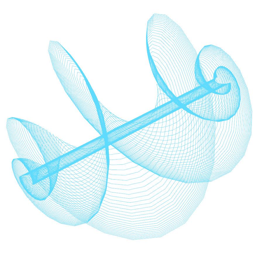
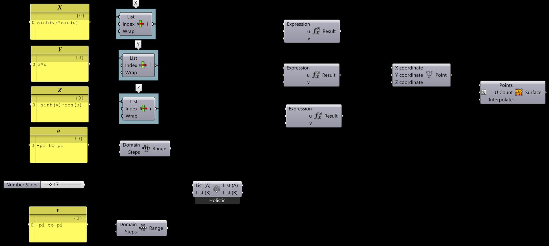
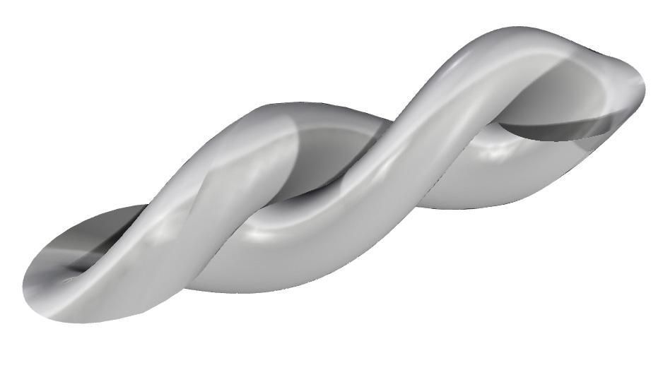
TWISTED SPHERE HELICOIDAL
Mathematical Expression Used For Twisted Sphere:
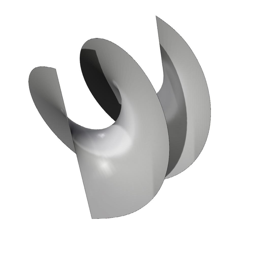
x = a cos(u) cos(v)
y = a sin(v) + b u
z = a sin(u) cos(v)
Domain: -pi to pi
Mathematical Expression Used For Helicoidal: sinh(v)*sin(u)
3*u
-sinh(v)*cos(u)
Domain: -pi to pi
30 31
SHELLS
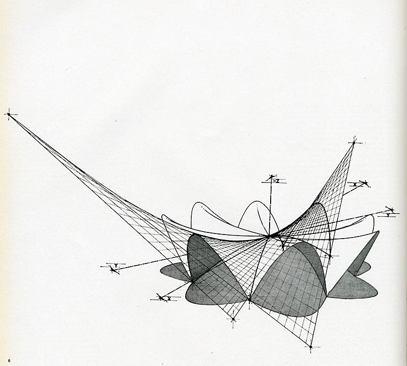
RECREATING FELIX CANDELA’S SHELLS
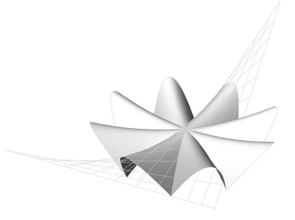
With the design for Los Manantiales, Felix Candela’s experimental form finding gave rise to an efficient, elegant, and enduring work of structural art. Comprised of four intersecting hypars, a strikingly thin roof surface creates a dramatic dining space. Built as Candela was establishing an international reputation as the foremost shell building, he demonstrated to the world his masterful combination of artistry and techni-
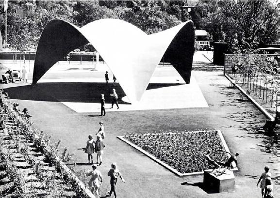
cal virtuoso. Los Manantiales was created as Candela’s mastery thin-shell concrete construction was solidifying. Initially conceived for another client on a different site, the structure found realization as a replacement for a wooden restaurant alongside a floating gardens filled canal in the Xochimilco area of Mexico City.
32 33
INTRODUCTION TO
GRASSHOPPER
Image Source: Internet
Grasshopper Definition
Los Manantiales / Felix Candela
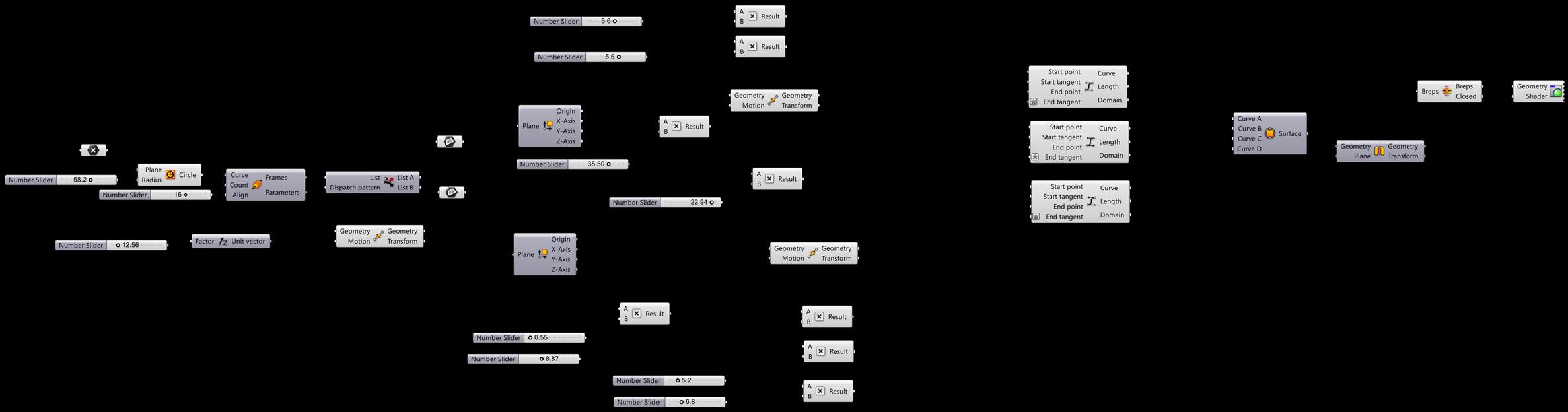
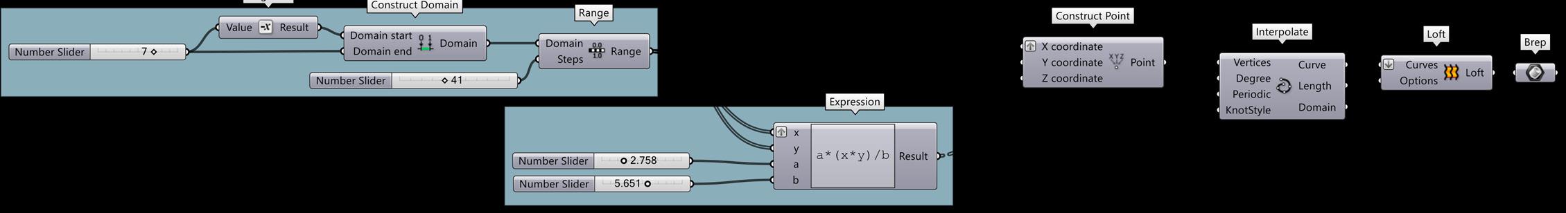
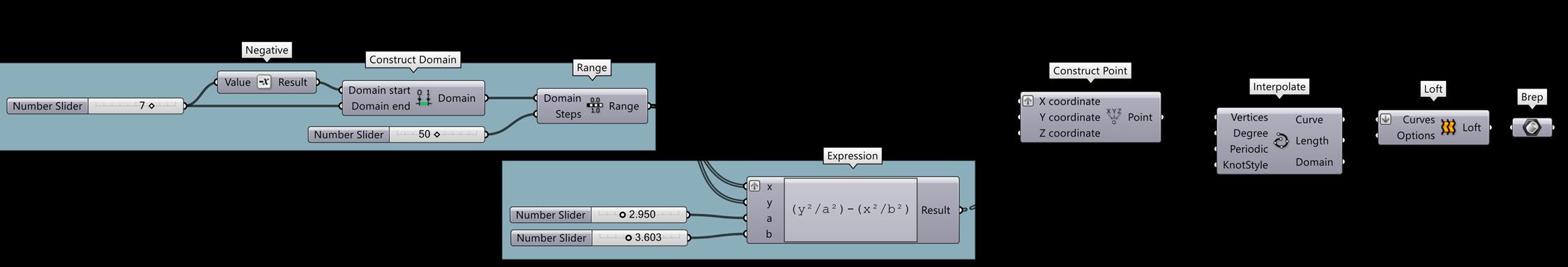
Recreating Felix Candela’s SHELL STRUCTURES
Geometry 01
Base Geometry with Expression: (y2/a2)-(x2/b2)
Geometry 02
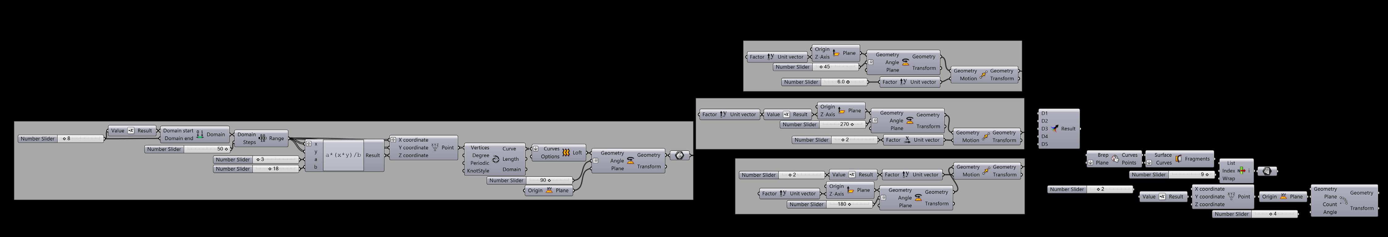
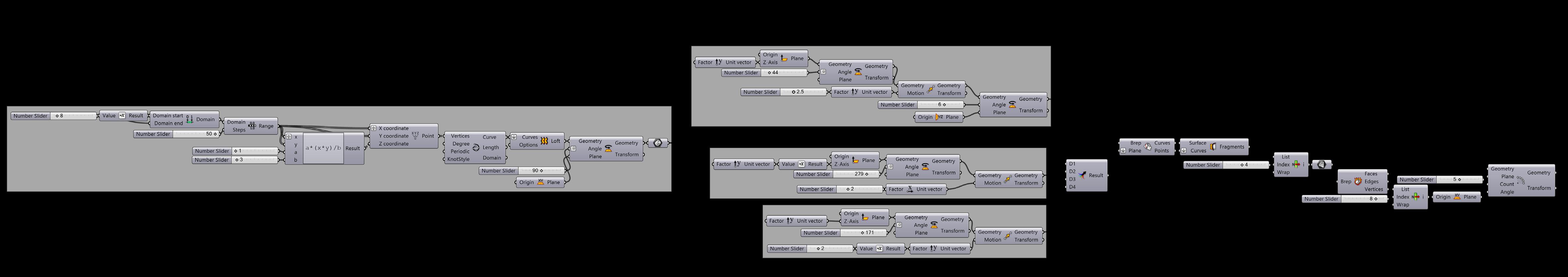
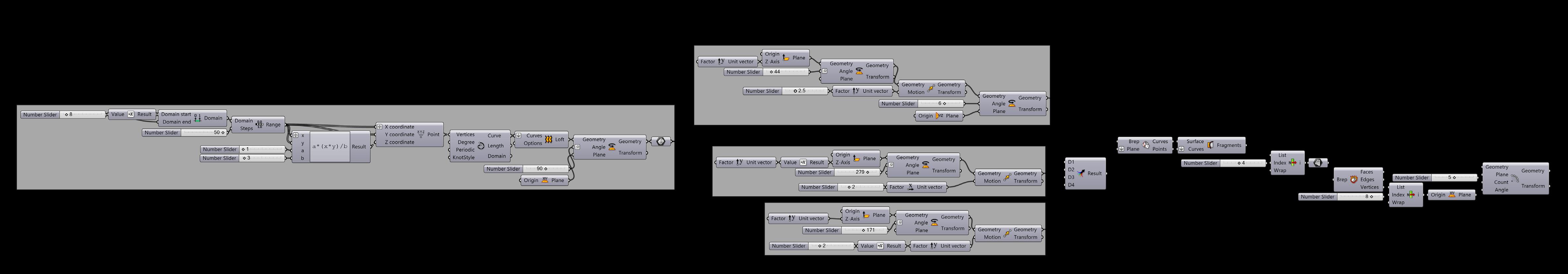
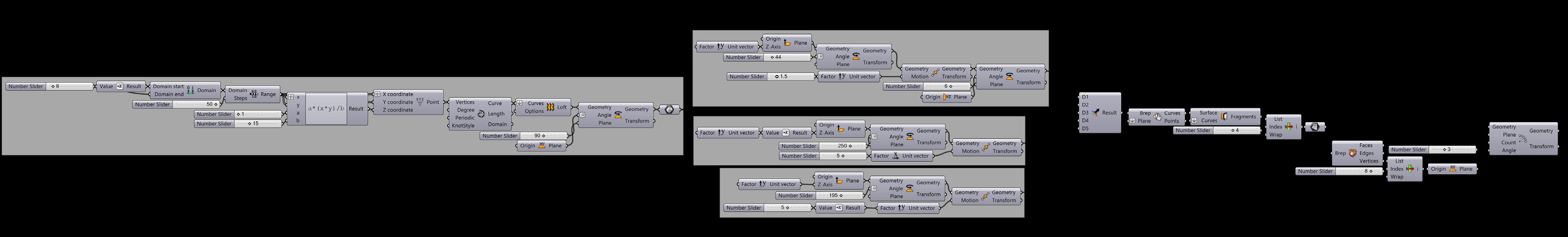
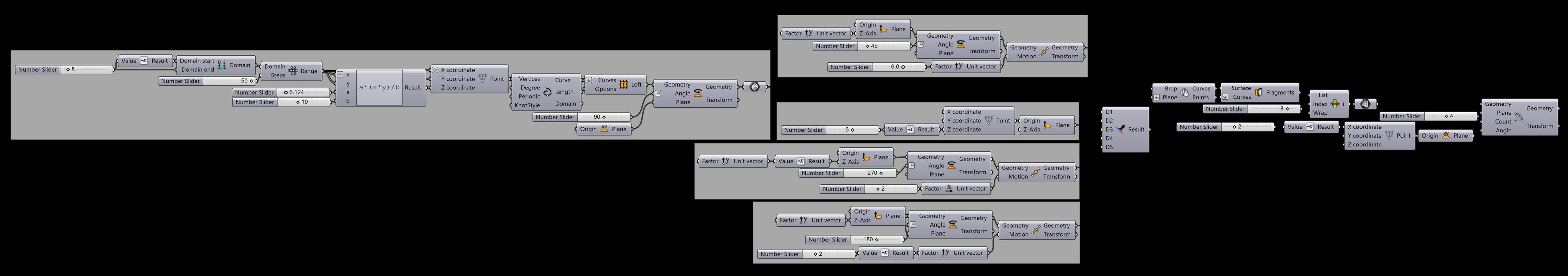
Base Geometry with Expression: a(x*y)/b
Geometry 03
Geometry 04
Geometry 05
34 35
36 37 Geometry 07 Geometry 06 Geometry 08 Geometry 09
38 39 Geometry 05 Geometry 04 Geometry 03
40 41 Geometry 08 Geometry 07 Geometry 06
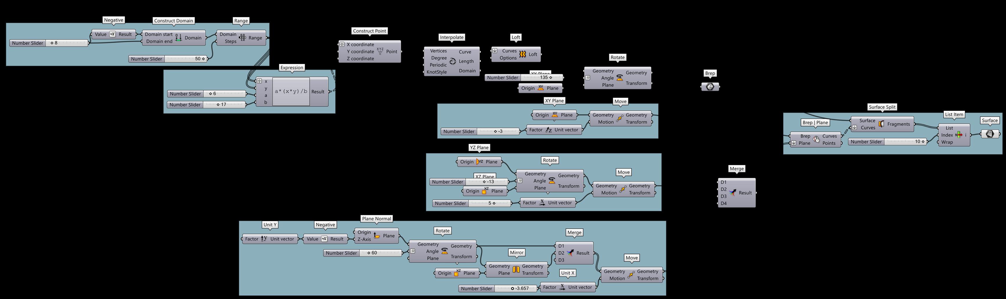
Base Geometry Derivation Logic
Achieved Shell Geometry
Base Geometry Derivation Logic
Achieved Shell Geometry
Base Geometry Derivation Logic
Achieved Shell Geometry
Base Geometry Derivation Logic
Achieved Shell Geometry
42 43
INTRODUCTION TO GRASSHOPPER
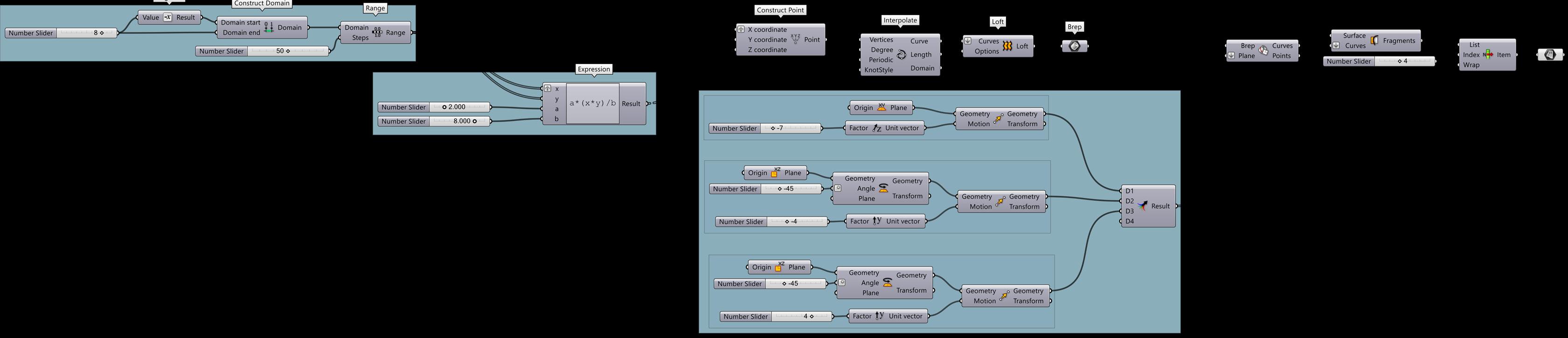
Base Geometry Derivation Logic
Achieved Shell Geometry
Base Geometry Derivation Logic
Achieved Shell Geometry
Base Geometry Derivation Logic
Achieved Shell Geometry
Base Geometry Derivation Logic
Achieved Shell Geometry
44 45
Chapter 03: Manipulation and Transformation
46 47
Single Attractor Point
Grasshopper Definition
GRASSHOPPER
ATTRACTORS
Attractors are points that act like virtual magnets - either attracting or repelling other objects. In Grasshopper, any geometry referenced from Rhino or created within Grasshopper can be used as an attractor. Attractors can influence any number of parameters of surrounding objects including scale, rotation, color, and position. These parameters are changed based on their relationship to the attractor geometry.
Multiple Attractor Points
Grasshopper Definition
48 49 SINGLE & MULTIPLE Attractor Points
INTRODUCTION TO
Attractor CURVE
FACADE
EXPLORING RESPONSIVE FACADE SYSTEMS
50
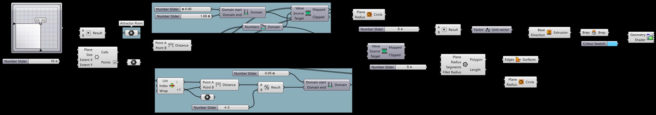
Grasshopper Definition
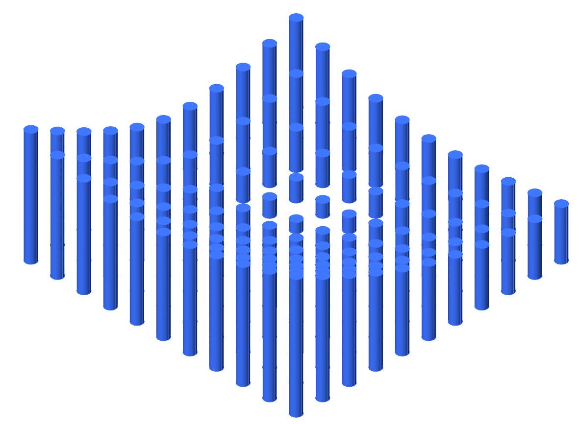
Grid of Cylinders Introduce an Attractor Curve
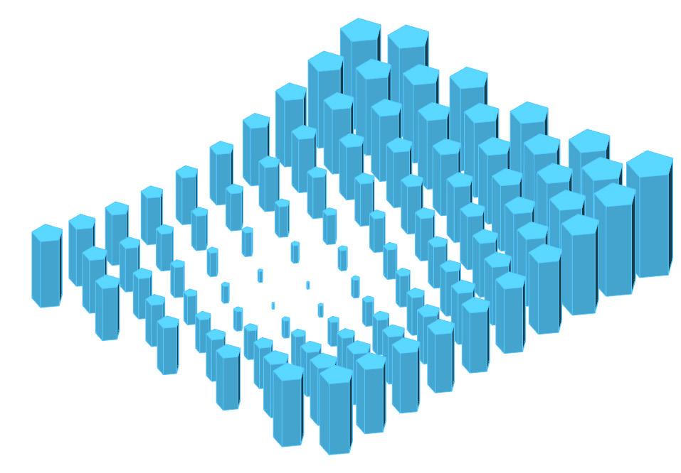
Resizing of cylinders based on Attractor Curve by Domain
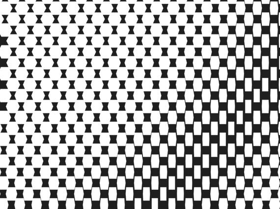
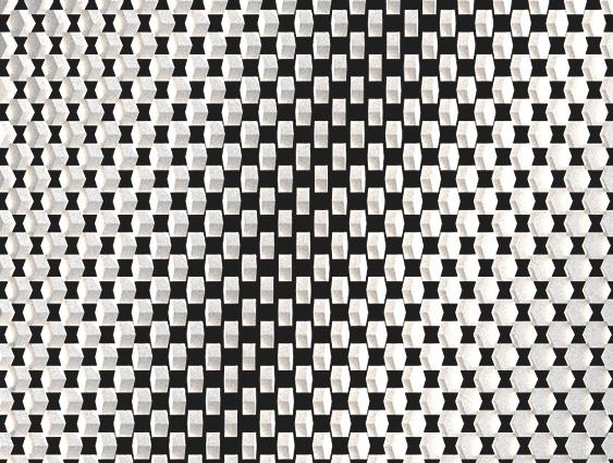
Create Rectangular Surface Divide Domain2 Isotrim to get Facade Segments
Surface Split (Splits Surface into Fragments to Create a Pattern) Dispatch Cull Pattern
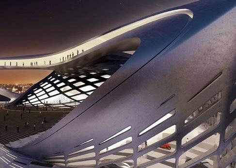
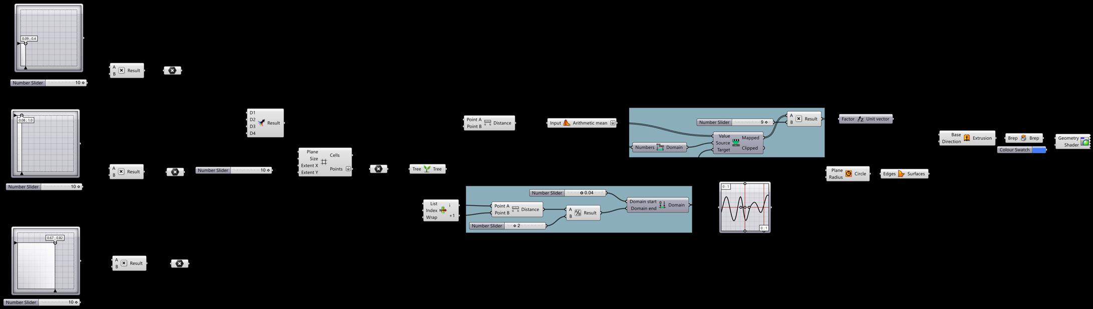
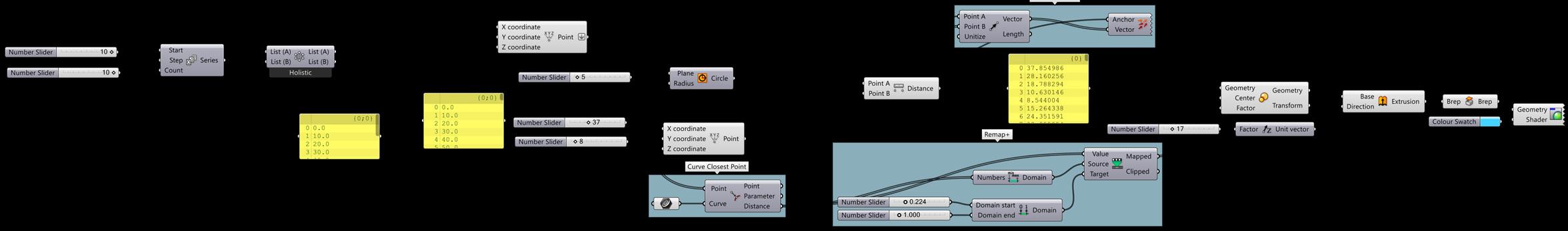
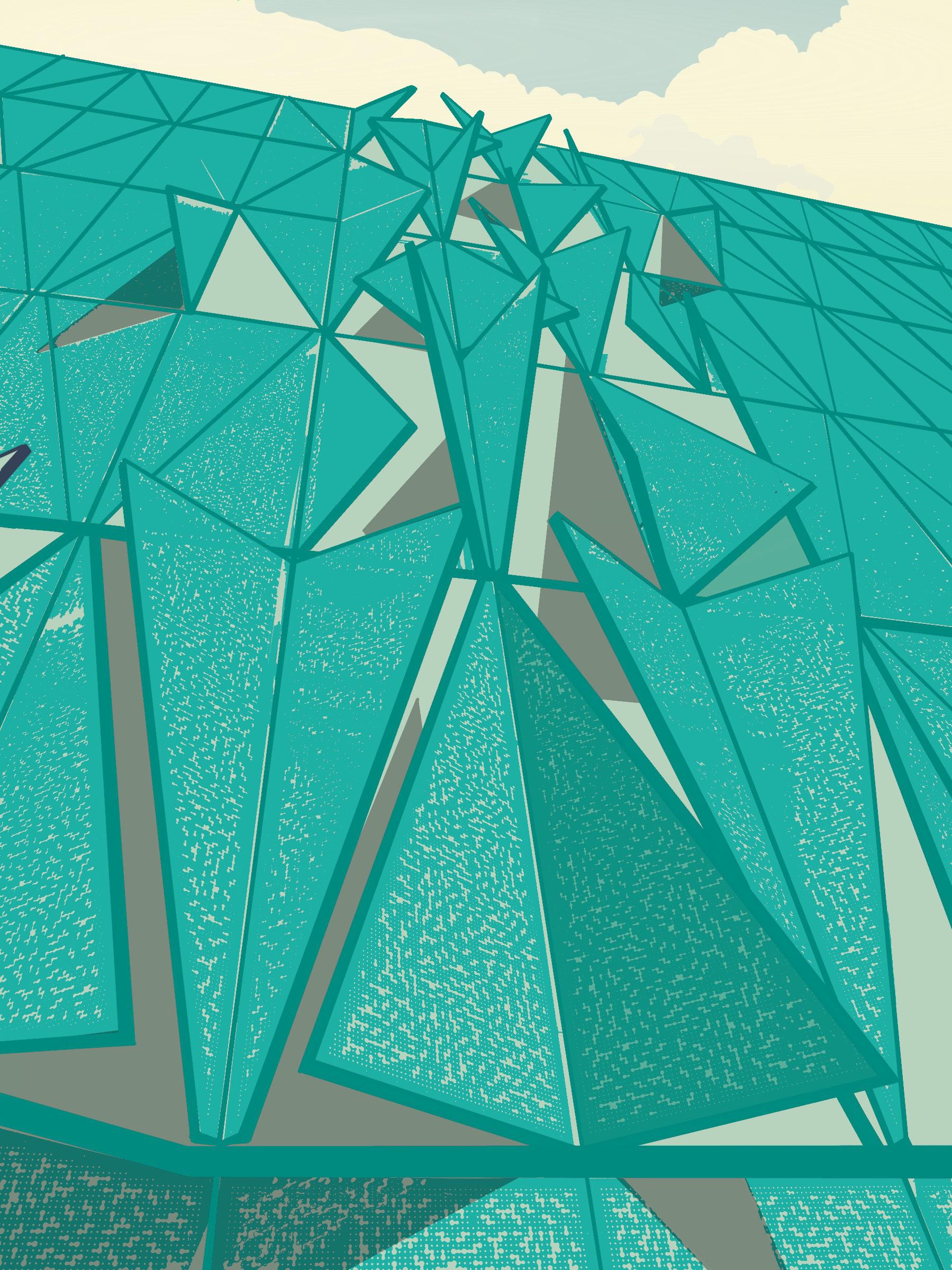
SDU FACADE
Henning Larsen Architects aimed to set a benchmark for green design with the Southern Denmark University building in Kolding, Denmark, featuring a climate-responsive kinetic facade and a triangular form
Rotational Logic Remap Numbers Rotate
Grasshopper Definition
52 53 INTRODUCTION TO
GRASSHOPPER
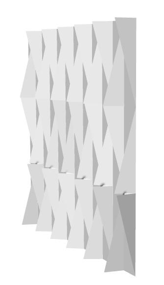
Generate Surface Rectangle
FACADE
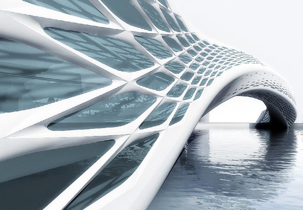
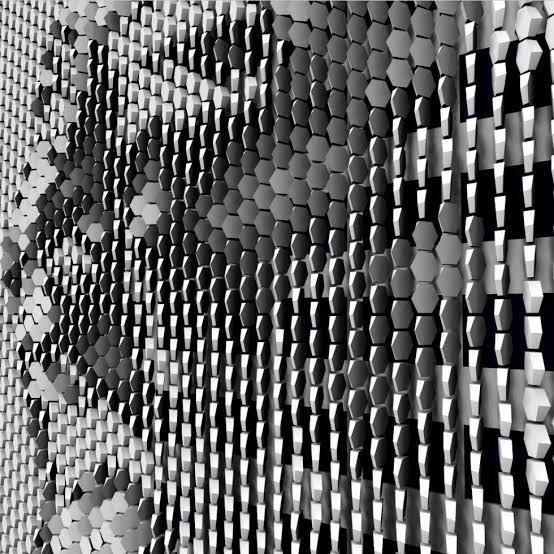
The research conceives sunscreens as performing a hybrid role: performing environmentally as a shade and glare modulator; while also enabling the façade to operate as a low resolution media screen that can generate income.
Current state of research: A prototype consisting of physical mock-ups and software has been developed and calibrated with simulations to provide an interactive proof of concept.
Step 01
Hybrid Responsive FACADE
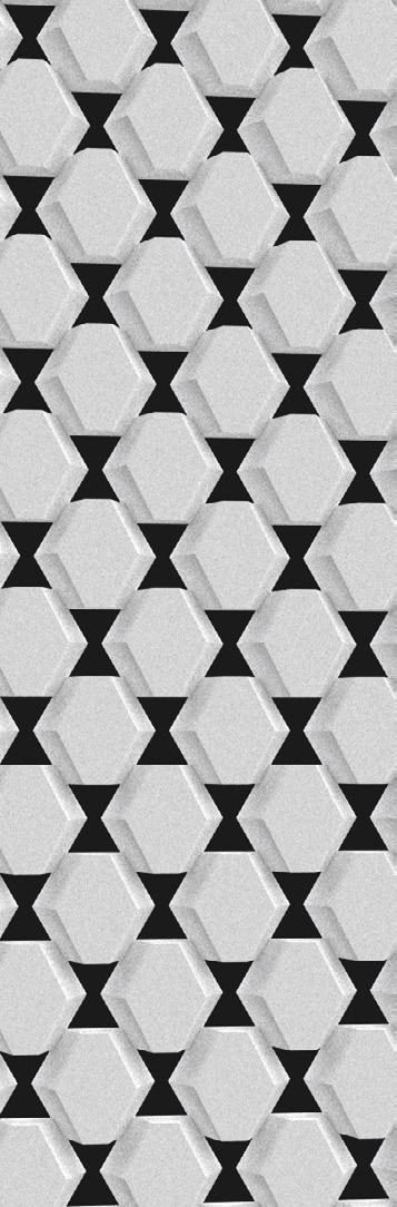
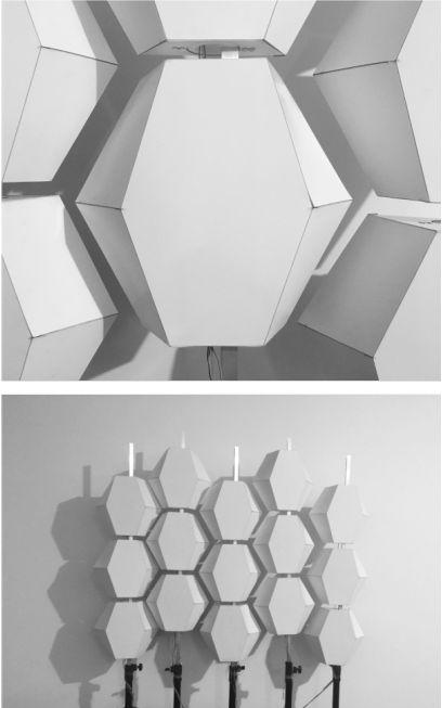
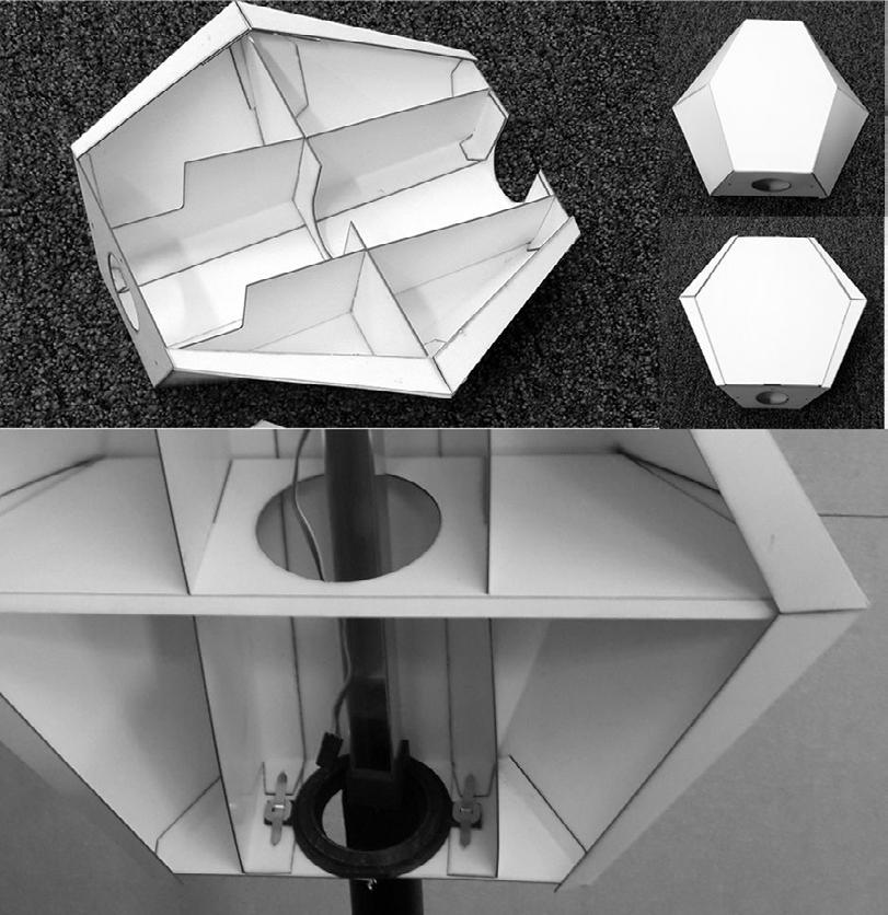
Next stage that requires funding: The research will shift to the design and fabrication of a solar powered autonomous panel, and research and testing of low maintenance actuators.
Divide Domain2 and Isotrim (Control U and V values) Create Cull Pattern
Deconstruct Brep and Extract Centroids
54 55
Facade Derivation Logic
INTRODUCTION
TO GRASSHOPPER HYBRID
Reference : IdEea Lab_Projects
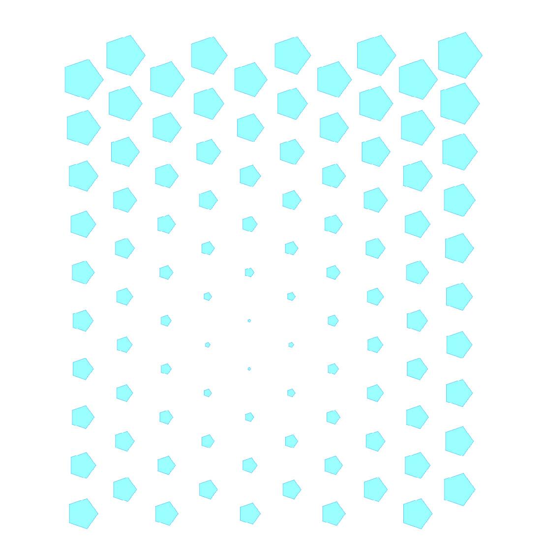
Polygon From Centroid Boundary Surfaces (Control Radius)
Rotate Module (Using Remap Numbers)
Deconstruct Brep and Extract Vertices
Create Axis of Rotation for each Module from Line SDL using Polygon Centroid
Extrude and Extact Points to Move for Module
Single Module of the Hybrid Facade
56 57
Step 02
Step 03
Create Hexagonal Grid
Deconstruct and Scale Each Cell
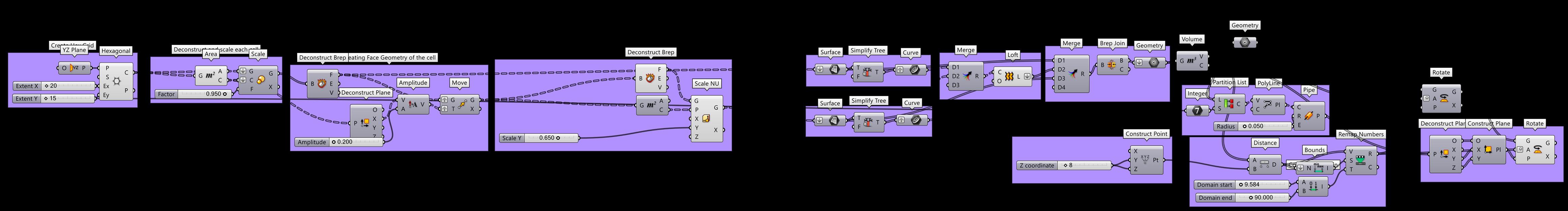
Create Face Each Cell Using Scale NU (Scale Non-Uniform)
Reworking Using HEXGRID
Simplified Grasshopper Definition
58 59
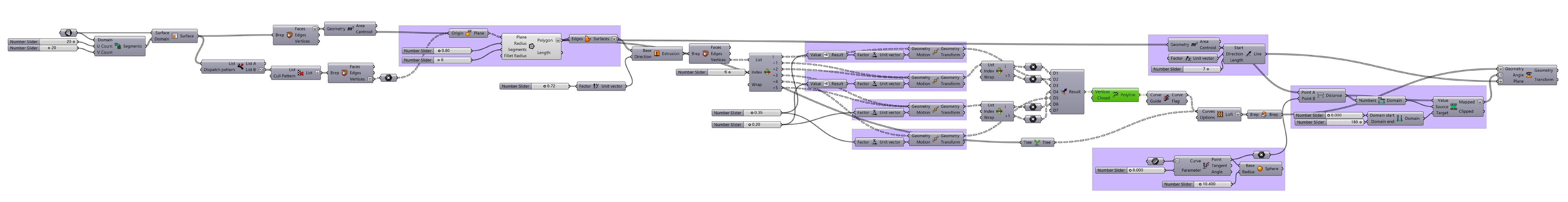
Initial Grasshopper Definition
Loft the Faces to get the Cell (Create Surface, Simplify Tree, Merge Data and Loft)
Chapter 04: Natural Phenomenon
60 61
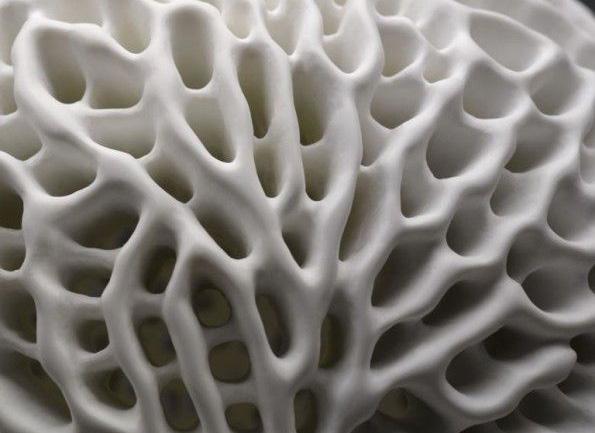
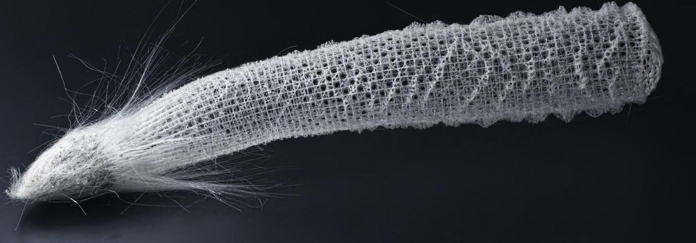
Anatomy of the GLASS SPONGE
Top Cylinder
Diameter
Bottom cylinder diameter
20-30 cm
GLASS SPONGE
Glass sponges are exclusively marine sponges with mineral skeletons composed of silica (glass) spicules. They have a worldwide distribution but are mainly restricted to deeper waters (200 to > 6000 m) where they grow attached to hard or soft substrates..
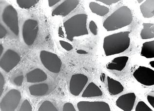
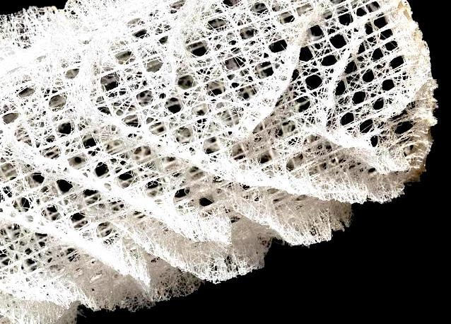
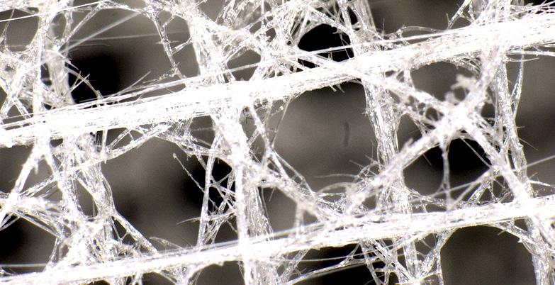
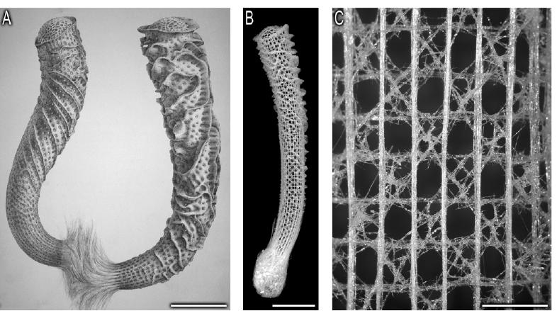
Hexactinellid SEA SPONGE
The complex and mechanically robust cage like skeletal system of hexantinellid sponge has proved to be particularly useful model system for investigating structure- function relationships in hierarchically ordered biological components.
Vertical Struts: 36 Horizontal Struts: 70 (Appx
62 63
Barbs
1. Anchor Spicules
Lower end of cylinder
Upper end of cylinder
2. Cylindrical cage
3-5 cm
2-3 cm
1:2)
3. Sieve Plate
NATURAL PHENOMENON
Structural logic
Quadrate Lattice
Horizontal + Vertical Bundles
Diagonal Bundles Ridge Formation
Fixed node Free node Verticals towards exterior, Horizontals towards interior
Lattice at lower end of cylinder more dense, less porus, overlap = x
Lattice at upper end of cylinder less dense, more porous, overlap = x/2
64 65 x x x x/2 x/2 2.5mm 4mm 5mm 5mm 8mm 2x 2x 10mm 10mm
66 67 Unfused Node Fused Node 900 900 900 900 900 900 The quadrate lattice spicule Lattice formation (plan) 1600 1800 Diagonal bracing Horizontal and vertical spicule bundles Octagonal openings Formation of a ridge 450 Every 4th lattice opening c/c between open cells Top: 6mm Bottom: 4mm 450
SPICULE AND NODE LEVEL Structure Local Geometry Spicule Regional Geometry
Global Geometry
Efficiency Optimization Growth Hierarchy
STRUCTURAL HEIRARCHY
Diagonal Members + Ridges
Material
Structural logic
Relationship between COMPONENTS
Skeleton
Skeletal Walls
Spicule Network
Constituent Spicules
Organic and Inorganic Composites
Inorganic and Organic Components
Cylinderical Skeletal Lattice
Anchoring Apparatus Cap Spiral Ridges Tapered Tube
Partially Ordered Network of Bundled Spicules Diagonally Ordered Spicule Bundles
Vertically and Horizontally Ordered Bundles
Underlying Square Grid of Cruciform Spicules
Basilia (Anchor Spicules)
Other Diactine, Tetractine and Hexactine Spicules Non-Planar Cruciform Spicules
Laminated Cement Laminated Spicules
Consolidated Silica Nanoparticles
Organic Interlayers
Axial Protien Filament
A : External Ridge system and terminal sieve plates
B : Underlying Siliceous cylinderical skeletal lattice.
C : Square grid and ordering of the vertical and horizontal components of the skeletal system
Reference: <Science Direct, Hierarchical assembly of the siliceous skeletal lattice of the hexactinellid sponge
Euplectella aspergillum> Journal of Structural Biology 158 (2007) 93–106
Workshop: AAVS, Biomorph_2016
68 69
HEIRARCHY LEVELS Component logic
Reference for Definition: OM.egvo
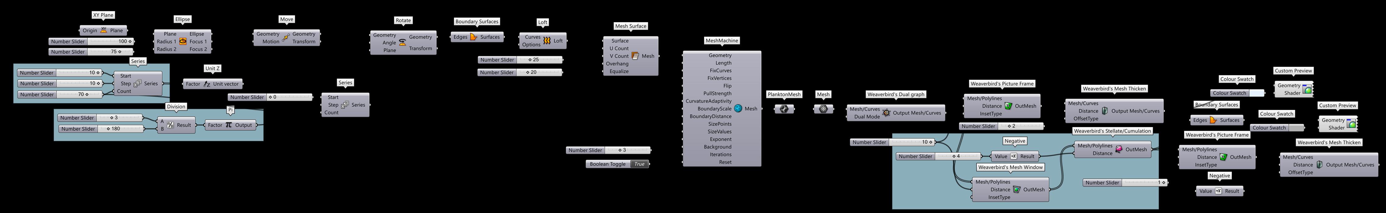
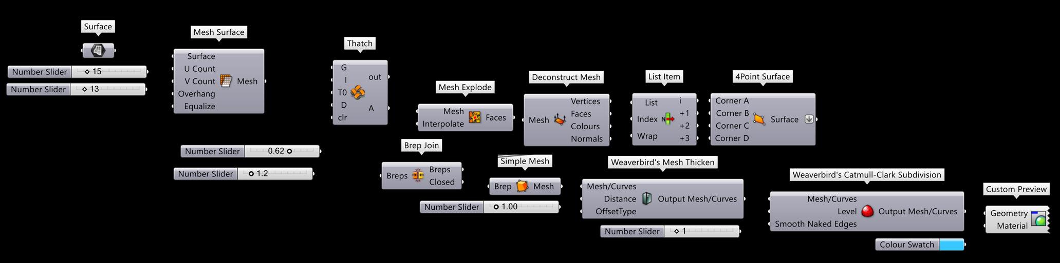
Create Ellipse Series
Rotate the Ellipse
Loft Mesh Surface Mesh Machine
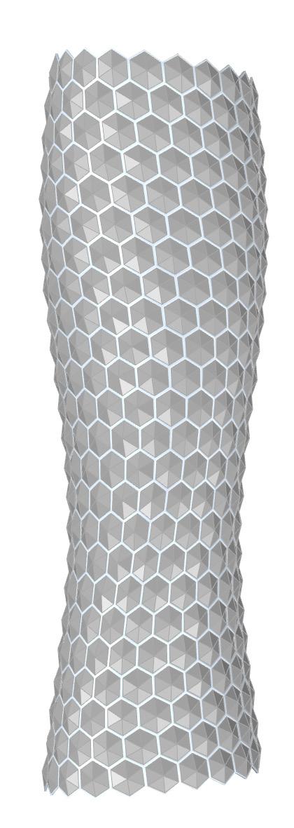
Creating the Exoskeleton using Weaverbird Components
70 71
Exploring EXOSKELETONS
Reference for Definition: OM.egvo
Create Circle
Perpendicular Frames
Rotate
Create Polygons
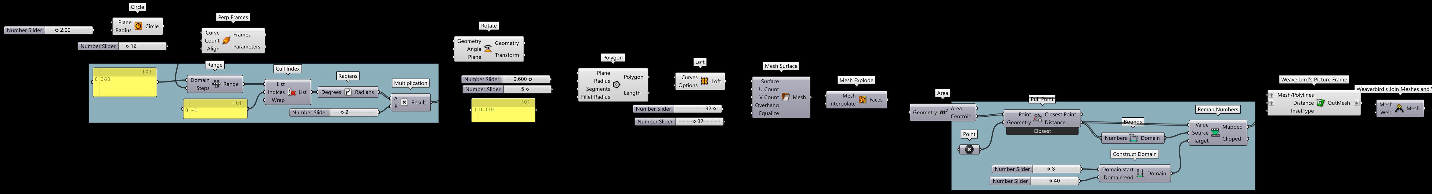
Create Closed Loft Mesh Surface
Explode Mesh
Extract Centroid
Remap
Join Meshes and Weld
Grasshopper Definition
72 73
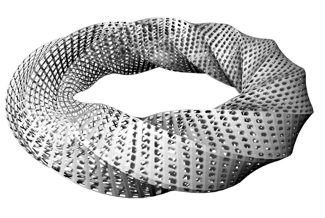
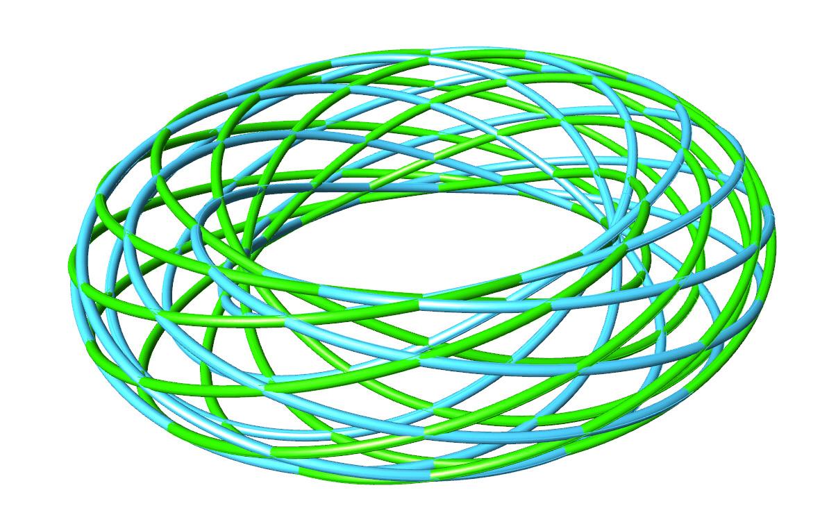
Exploring MESH
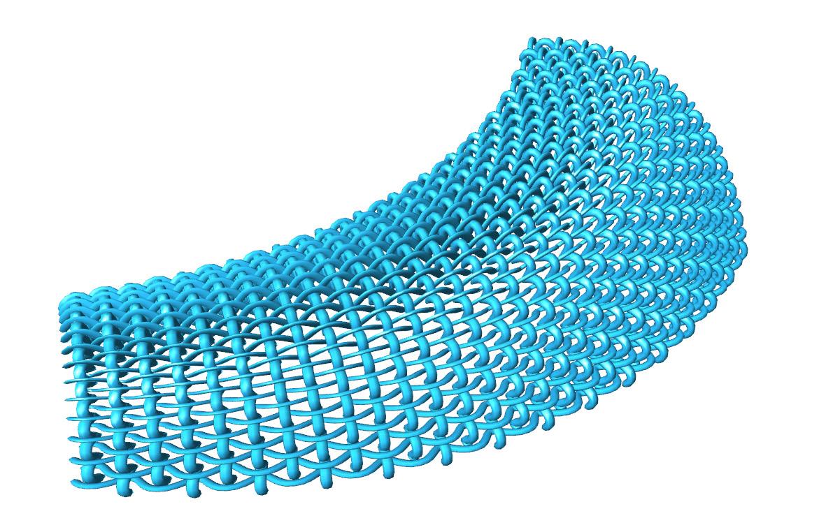
Create 2 Circles Use Perpendicular Frames
Evaluate Curve to find Points Interpolate to Join
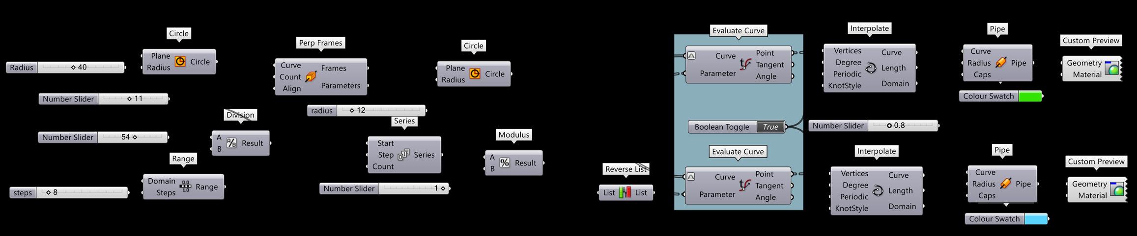
Alter Radius Number Slider to change Geometry
Reference for Definition: Parametric House
Grasshopper Definition
Reference for Definition: Parametric House
Grasshopper Definition
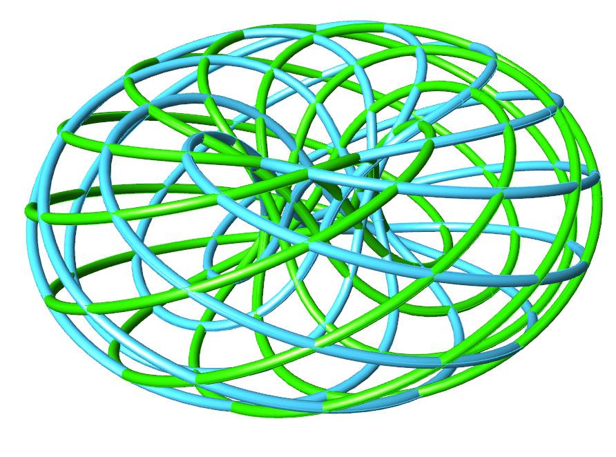
74 75 Exploring WEAVE
PARAMETRIC SOFTWARES
ANAHITA GHATAGE
anahitaghatage29@gmail.com
DA1905
TUTORS: RIPPLE PATEL | MUGDHA GANDHI
76