
SELECTED WORKS

0432512992
amypcollins.01@gmail.com
in/amy-collins-240929104/ Melbourne, Victoria
Recent Graduate from Bachelor of Design (Architecture). A creative, flexible, and high energy individual. With a passion for designing harmonious spaces between the built form and environment. An excellent communicator with a high attention detail and drive to succeed. Accompanying proficient software skills with over 4 years experience in Autocad and Revit.
Developing a strong foundational knowledge in construction technologies, building legislations and Australian Standards, which has further aided my design development within Architecture.
Having the ability to collaborate on various design projects as part of a team and individually, gaining the skills to convey ideas in creative and abstract ways.
Take a journey through my portfolio from selected design works, public exhibitions, and technical drawings.

Project : Academic / 2022
Participants: Individual
Software : Rhino, Adobe Photoshop, Adobe Illustrator

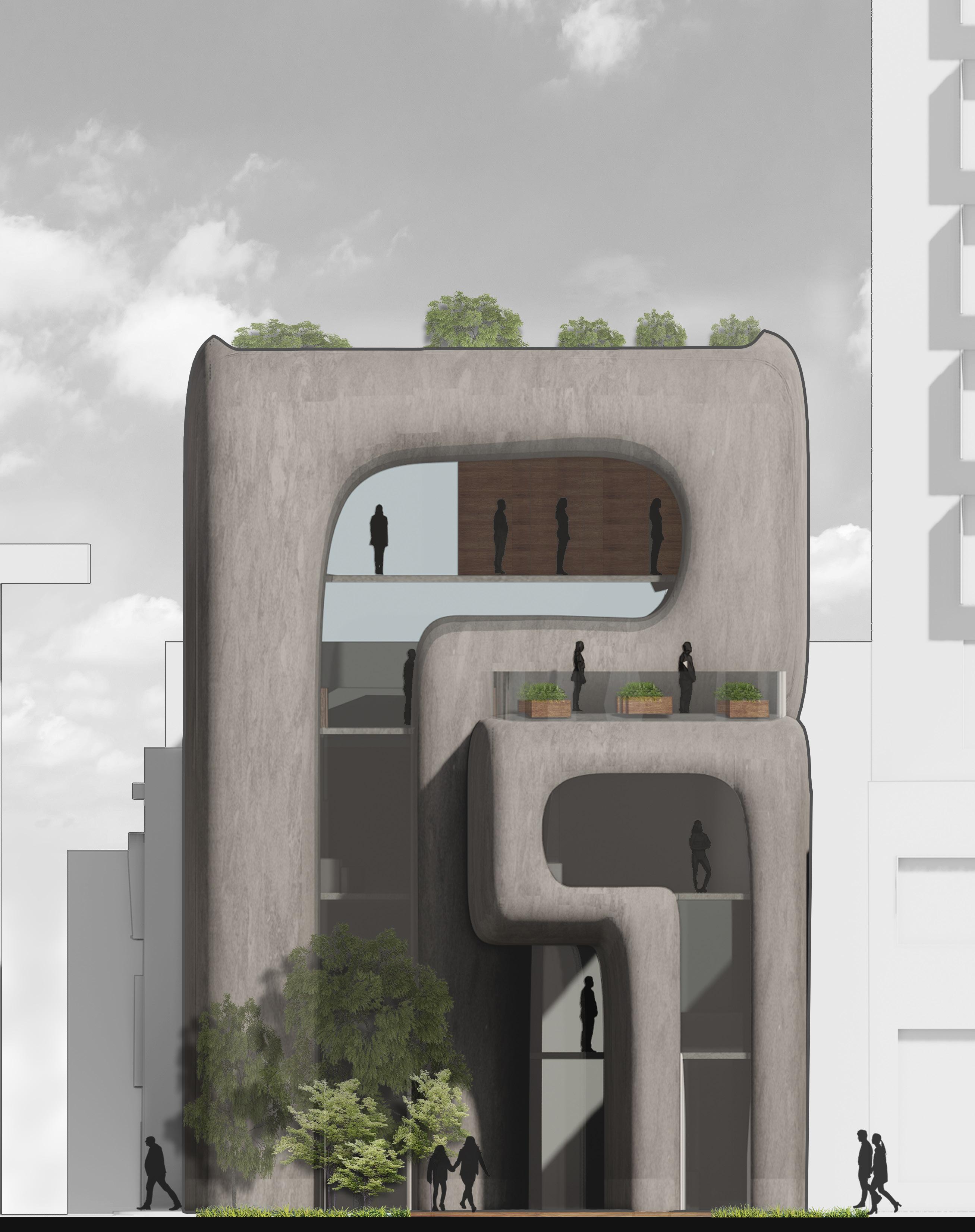
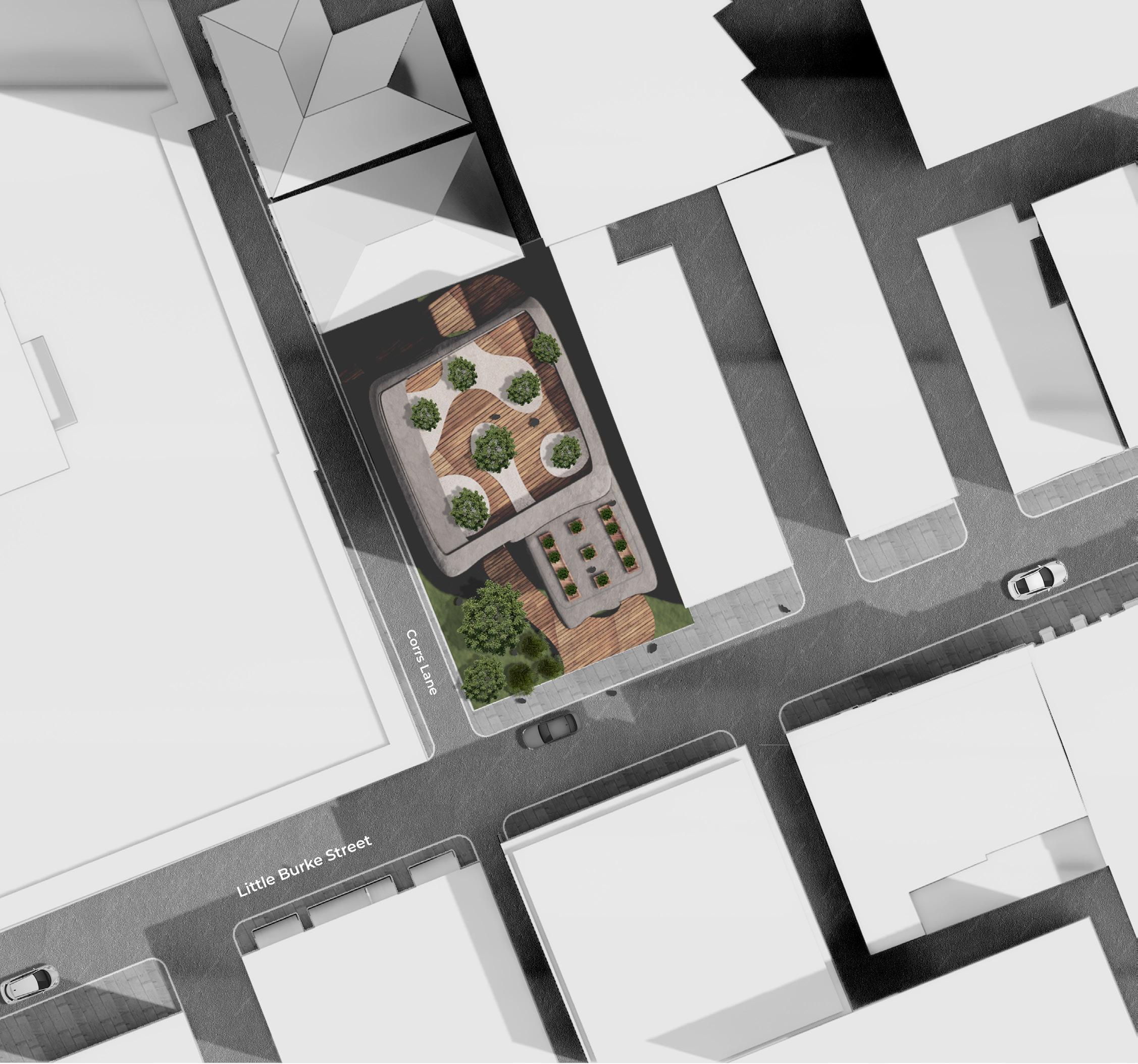
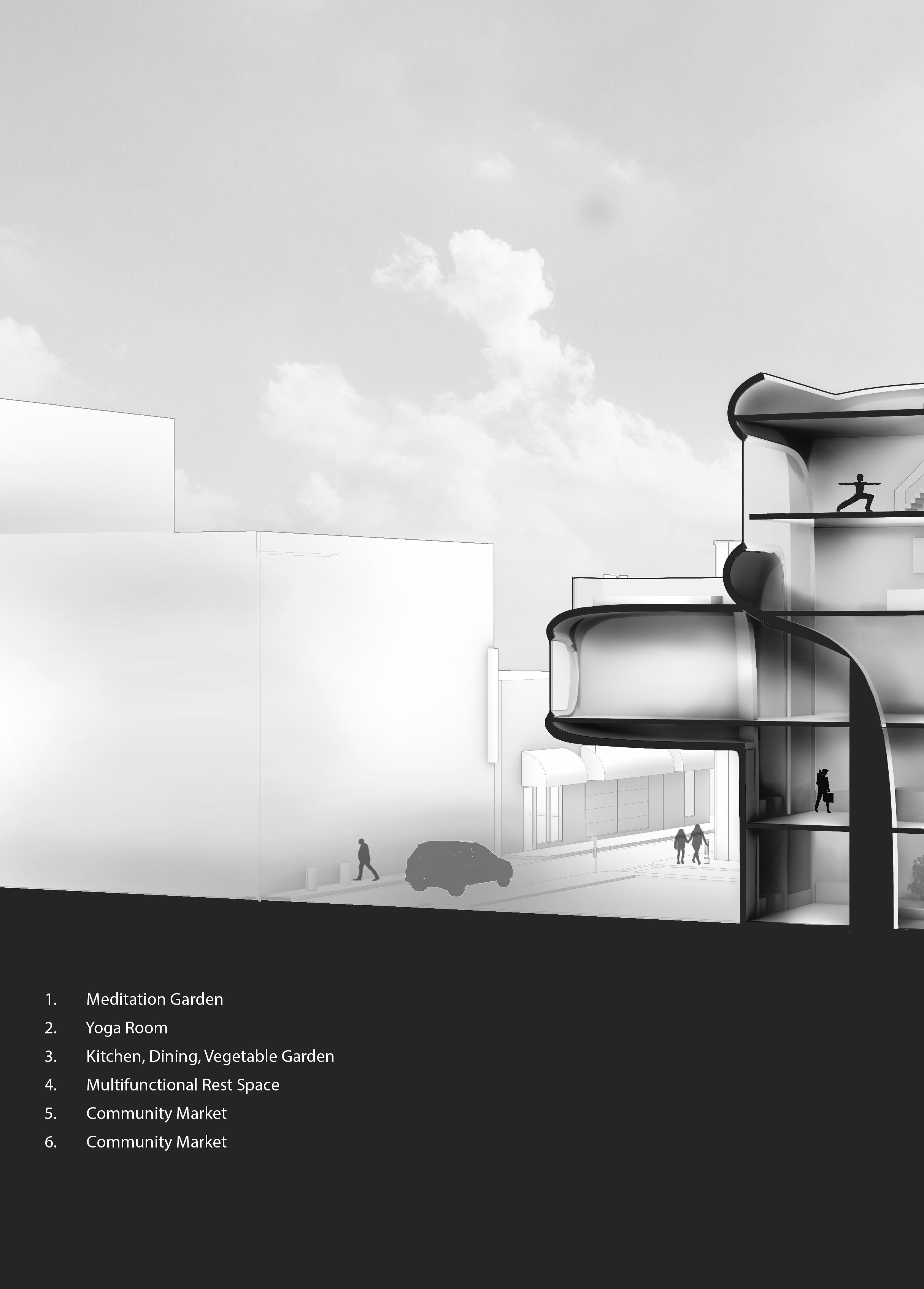
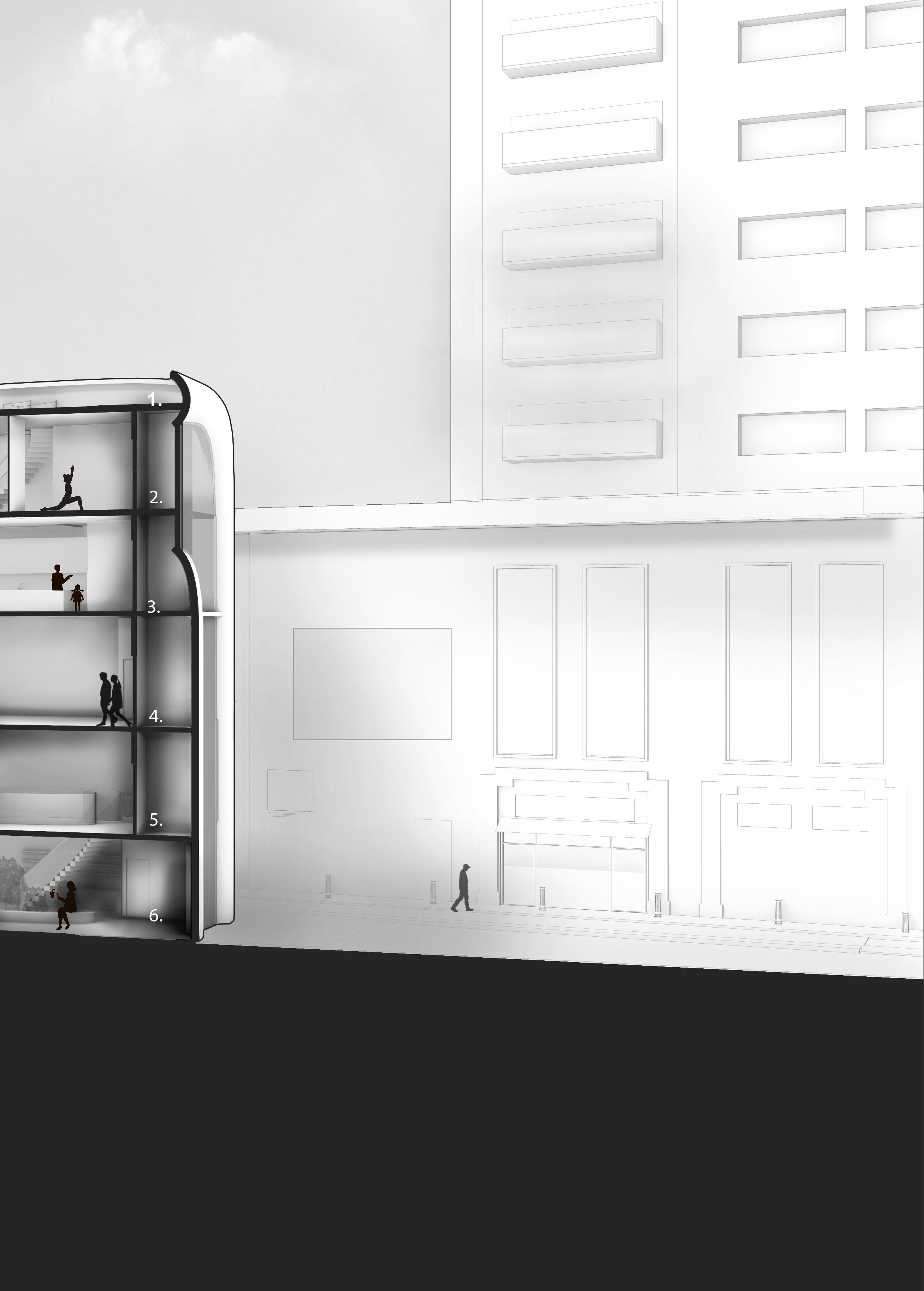
Taking a siteless curved form and developing into medium scale commerical wellness centre.
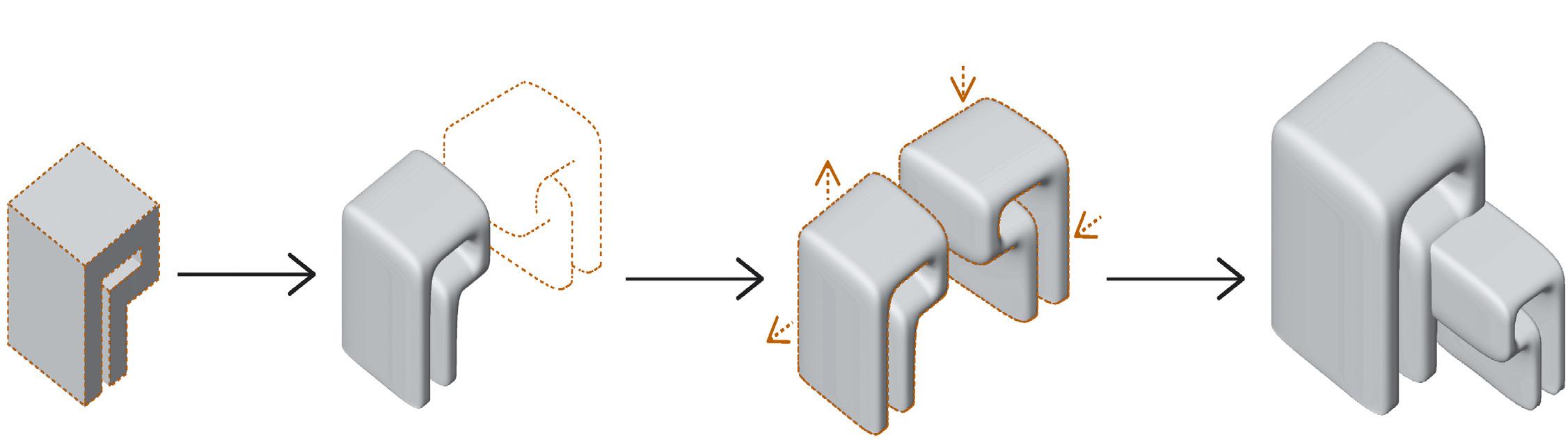
The siteless form was explored in many ways and scales to explore how form can translate into a functional space. This form curve was doubled, mirrored and scaled to create the final shape.
The form then became the exterior shell. I sculpted the form to allow for windows and added interior walls to develop this form into a building. Working with hand sketching, 3d modeling and 2d linework to develop this building.
Project : Academic / 2019
Participants: Group of two Software : Rhino, Enscape, Adobe Photoshop, Adobe Illustrator
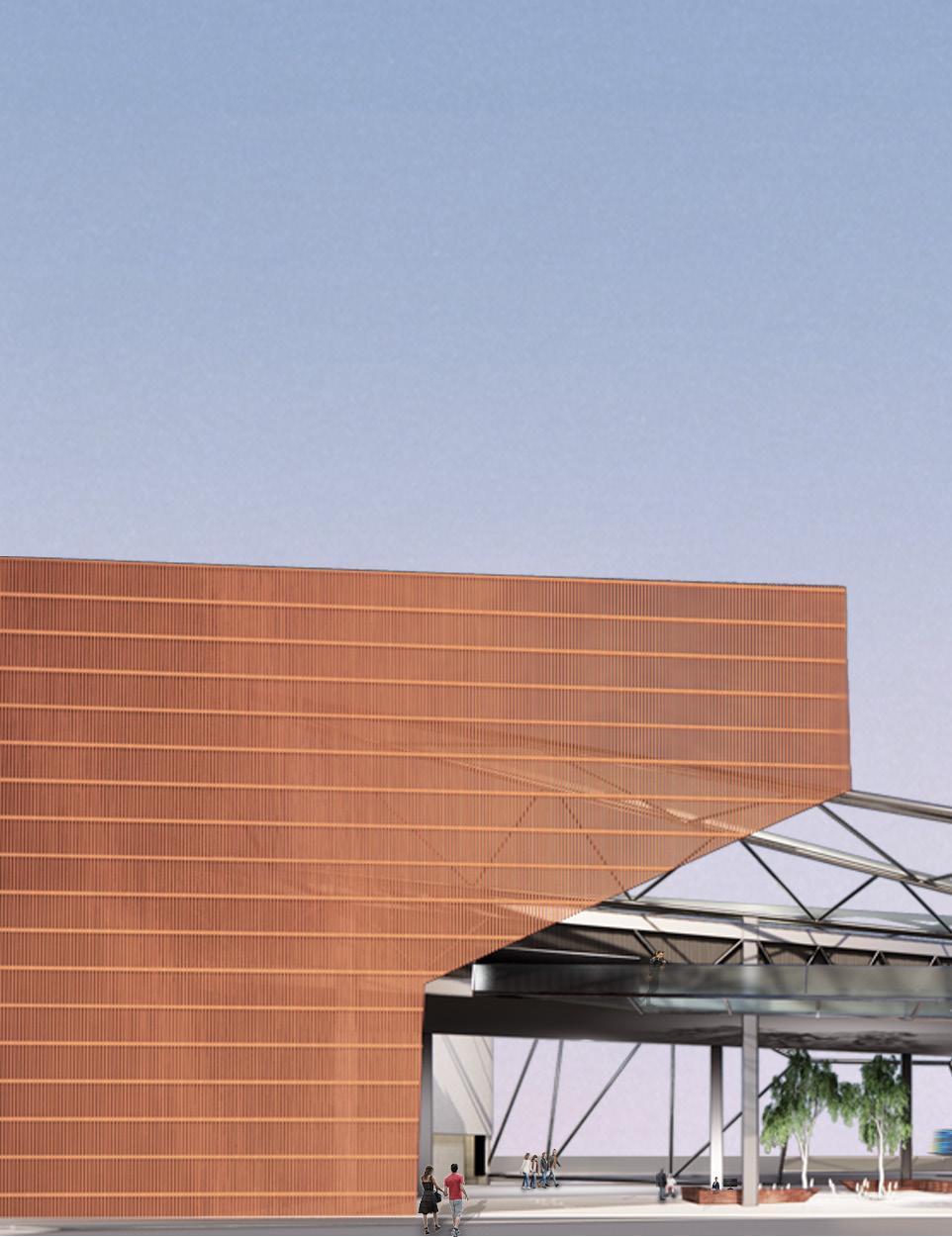
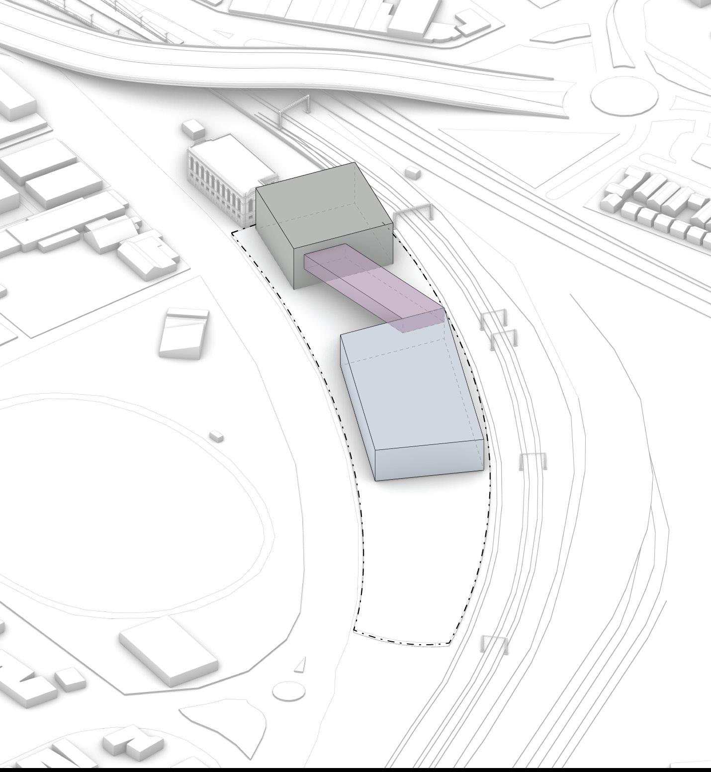
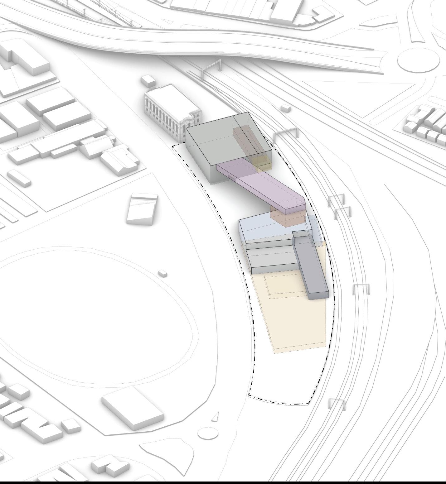
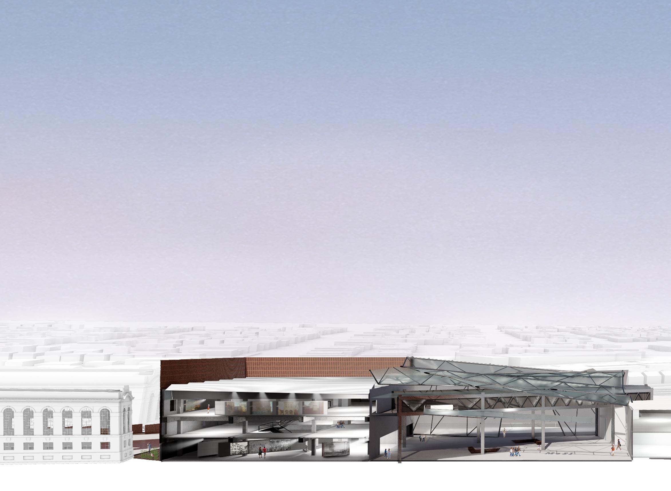
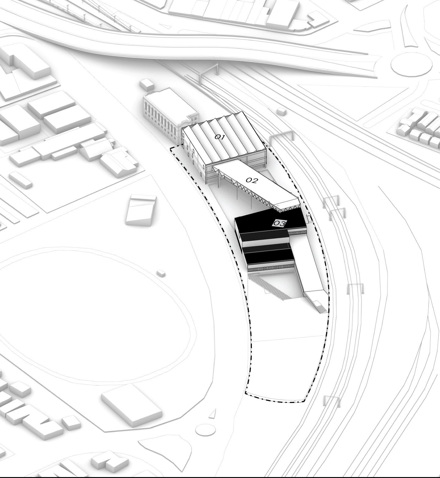
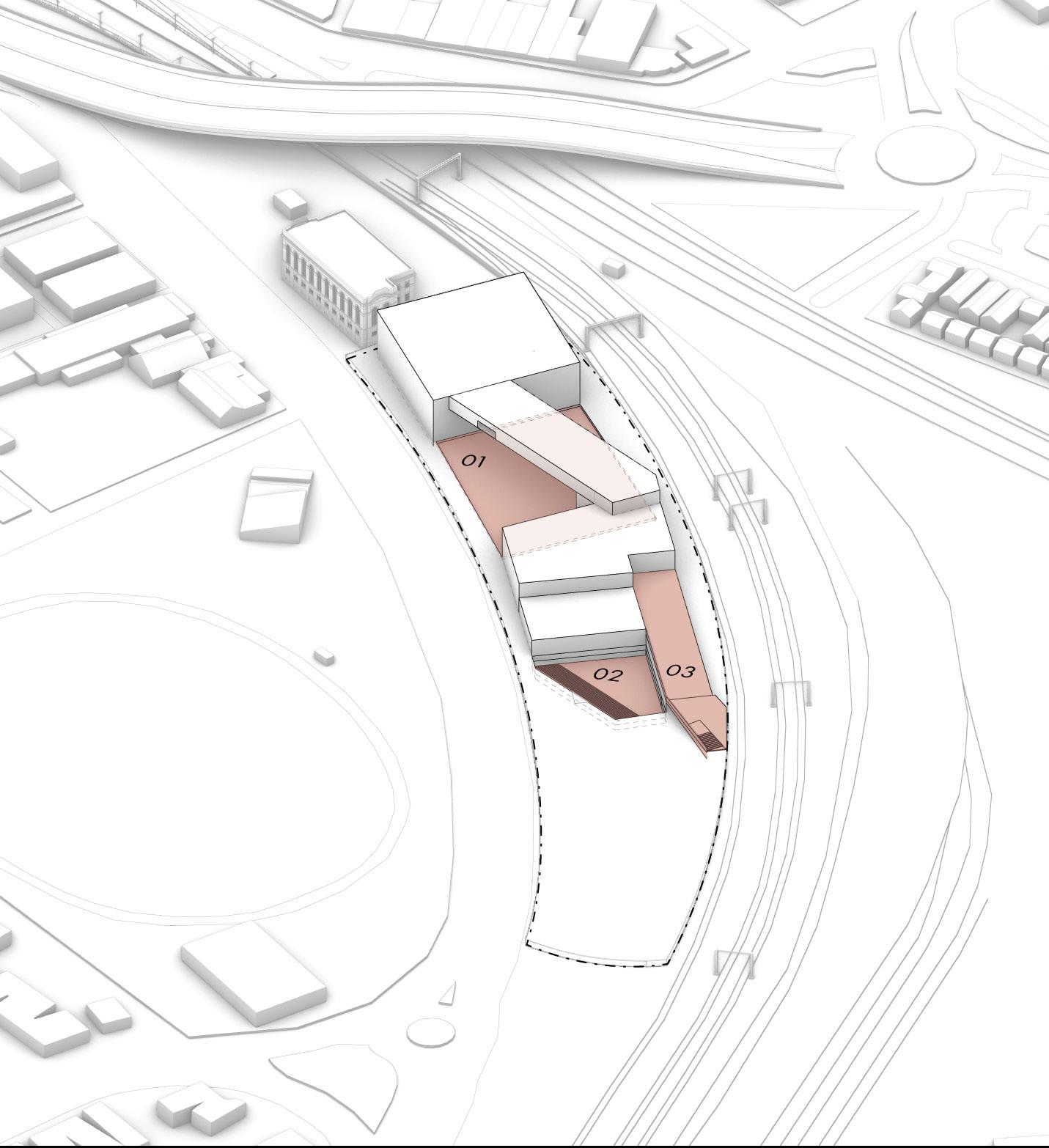
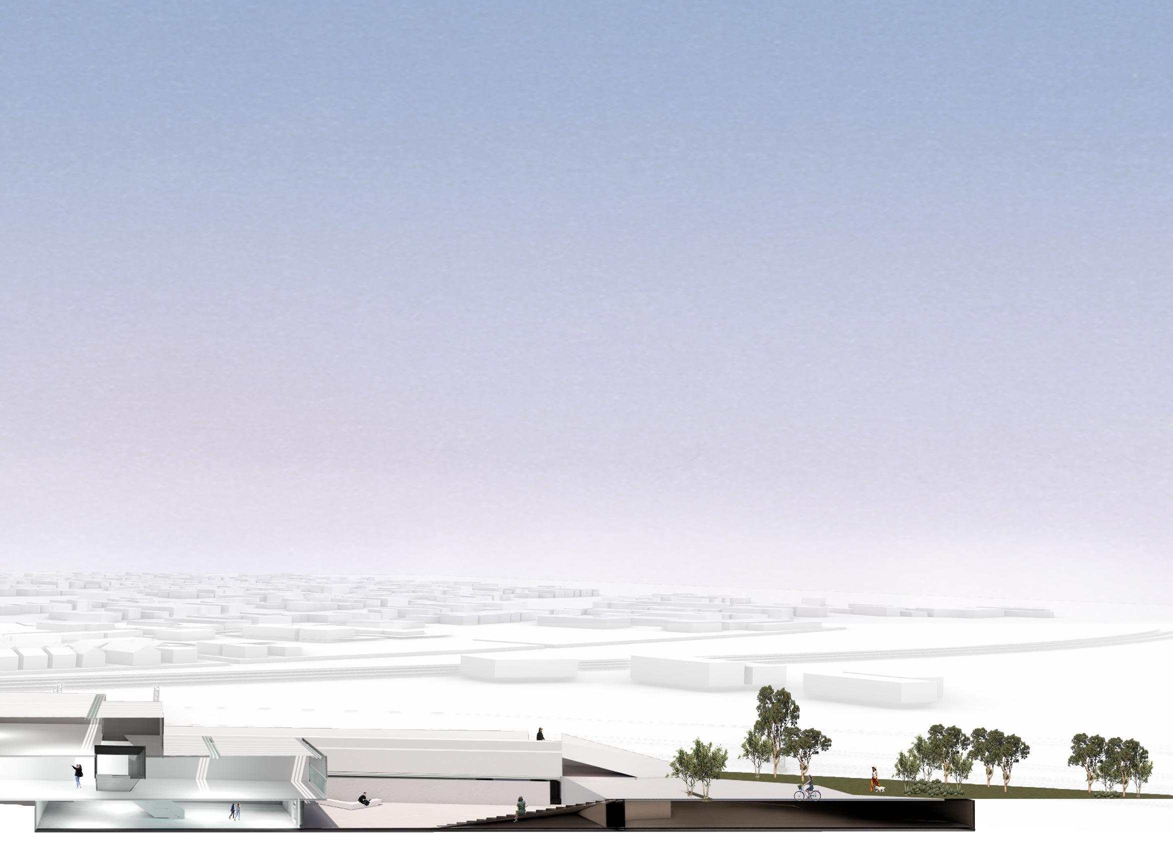
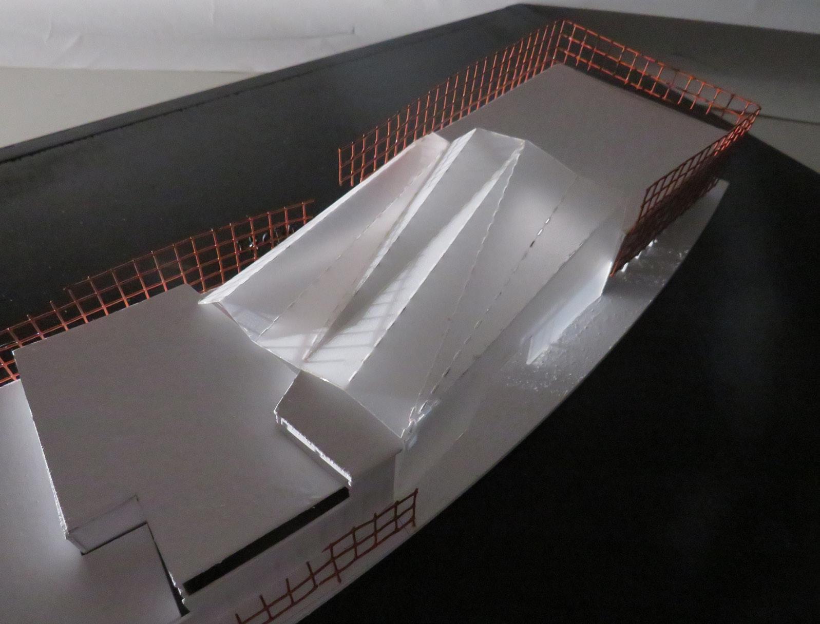
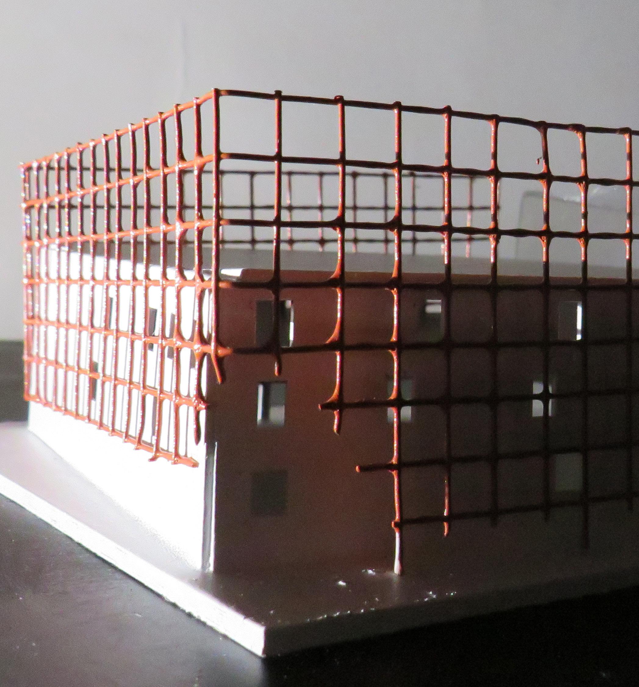
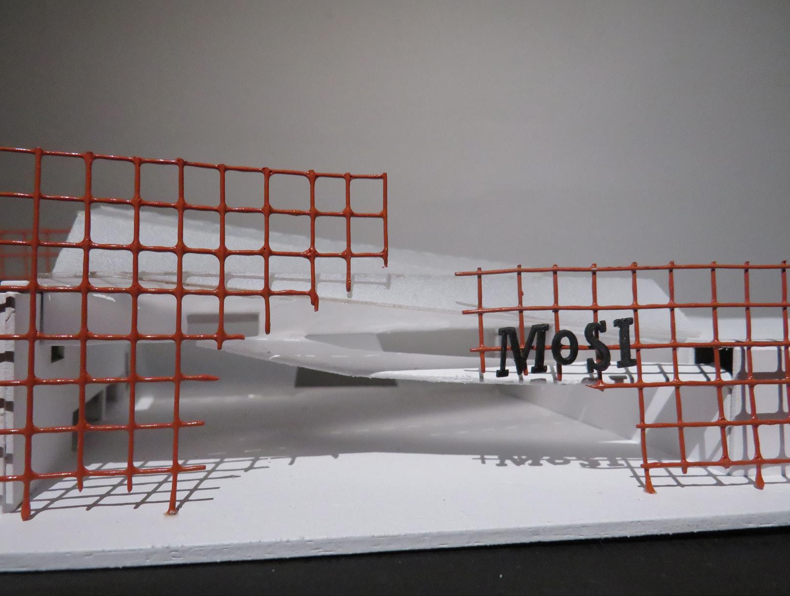
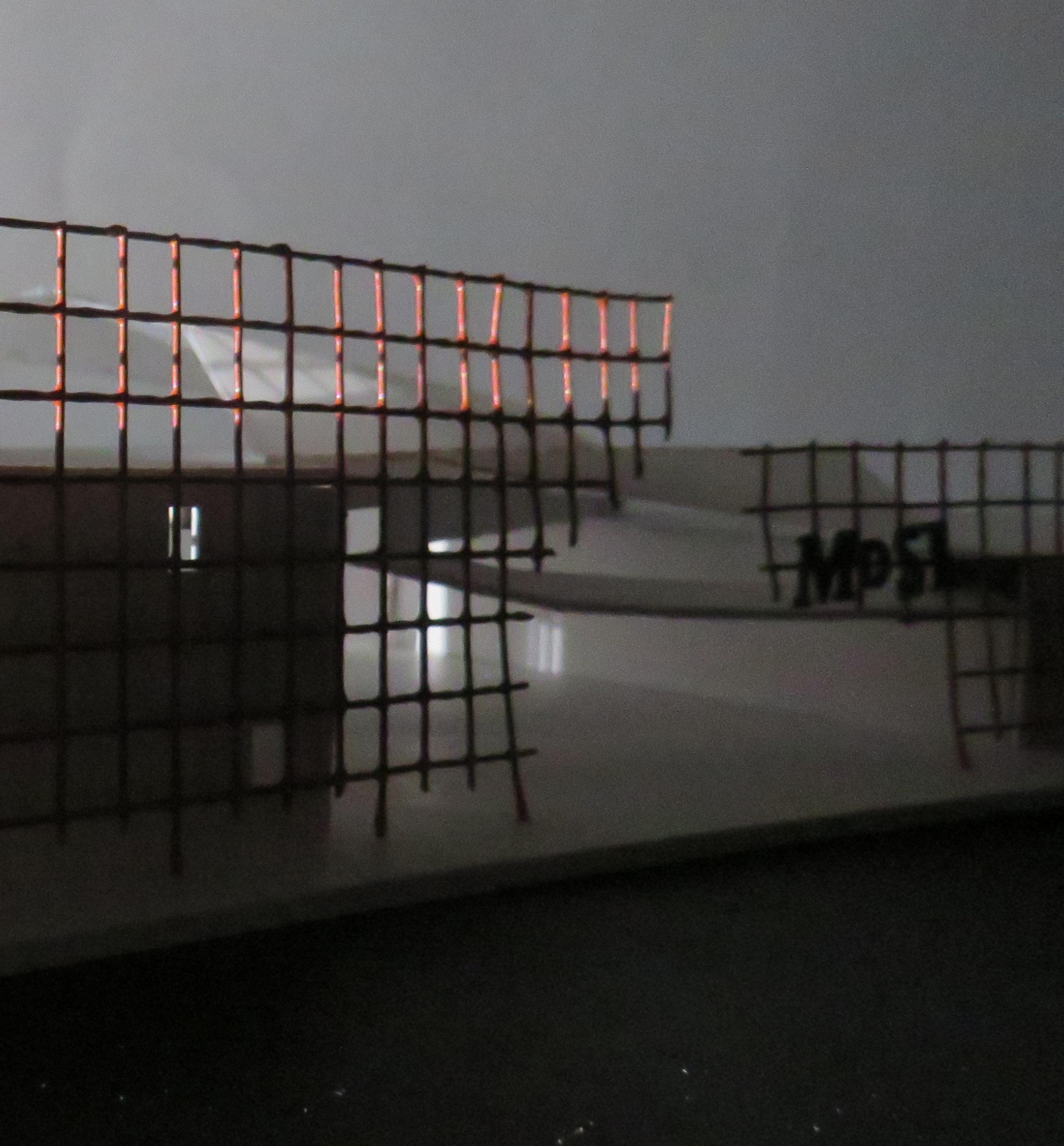
Museum MoSI showcases the hidden identity of the Western Melbourne Suburb Newport. Now considered to have no identity, the true foundational identity of Newport is heavily industrial. We propose to bring back that industrial language and culture, through a sense of permanence, becoming lost under the rubble of gentrification. MoSI aims give back the identity the identity of Newport, and allows the Newport Community to Breathe their own Unique Future.


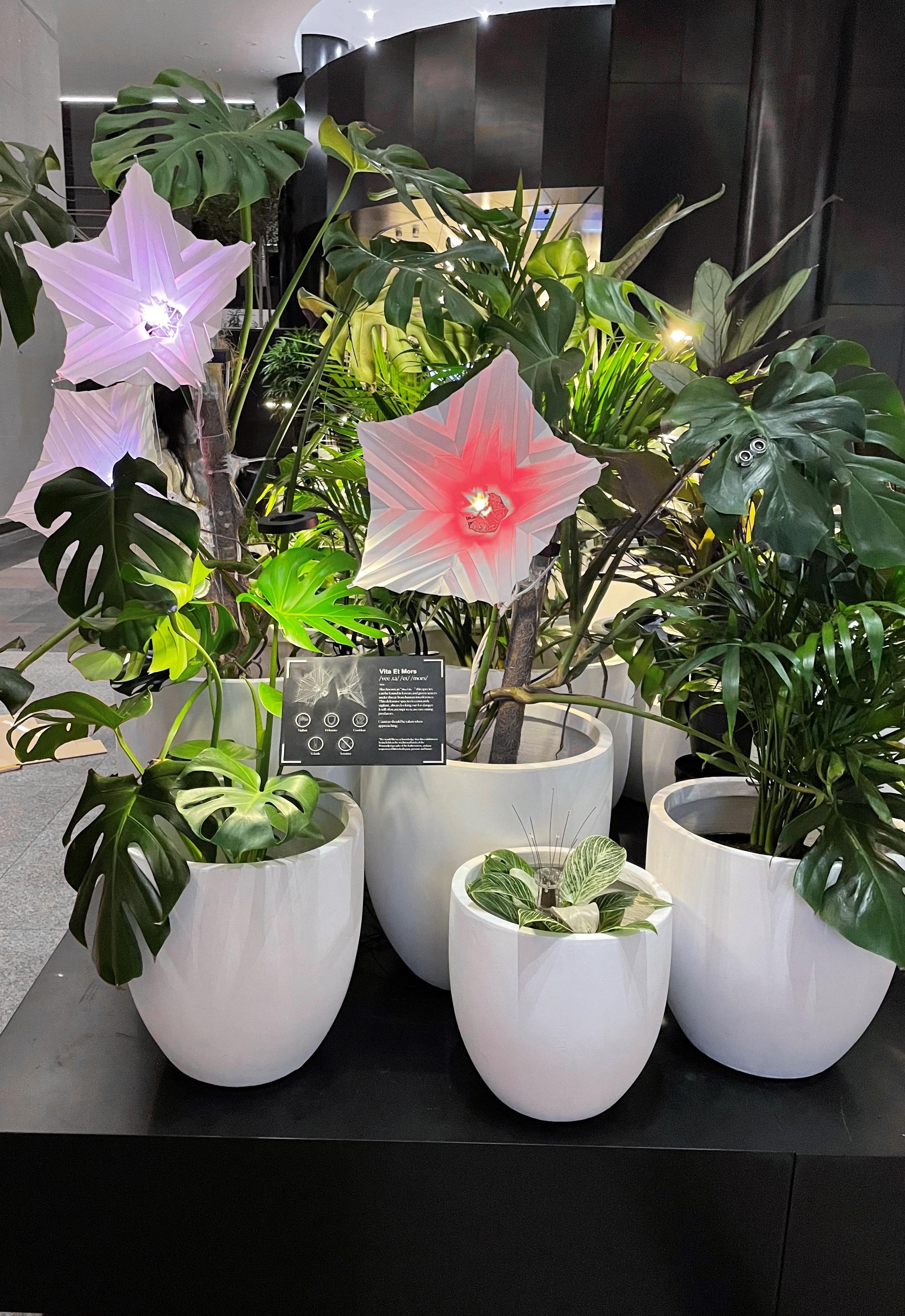
Project : Public Exhibtion / 2022
Participants: Four member team, Individually developed the flower petal, connections, base lighting.
Software : Rhino, Grasshopper, Adruino, Adobe Illustrator
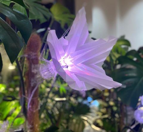
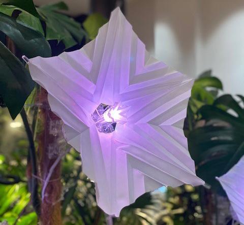
The night flower resembles a future world where humanity has failed to protect the natural environment. Flowers have evolved into aggressive cybernetic organisms - part-robot; Half organic, half mechatronic beings that have learnt to protect themselves from their persecutors, human beings.
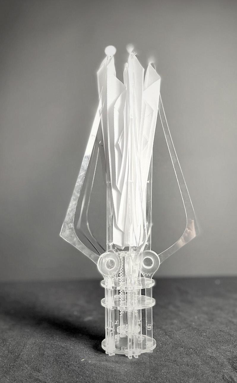
Made from 3mm Acrylic, the mechanism uses a rack and pinion to open and close the mid ribs of the flower. Attached to the mid ribs is the petal design - an origami inspired pattern made using polyester that reveals itself as the mechanism opens, and folds as it closes. The flower responds to the movement of humans to tell its story with mechanism opening up to protect itself aggressively if a person gets to close to it, and staying vigilant and closed when solitude.
The flower is a theoretical concept that is inspired by the environmental challenges that humanity and the natural world face. It draws inspiration from how organisms evolve, the changing in characteristics of a species over several generation.
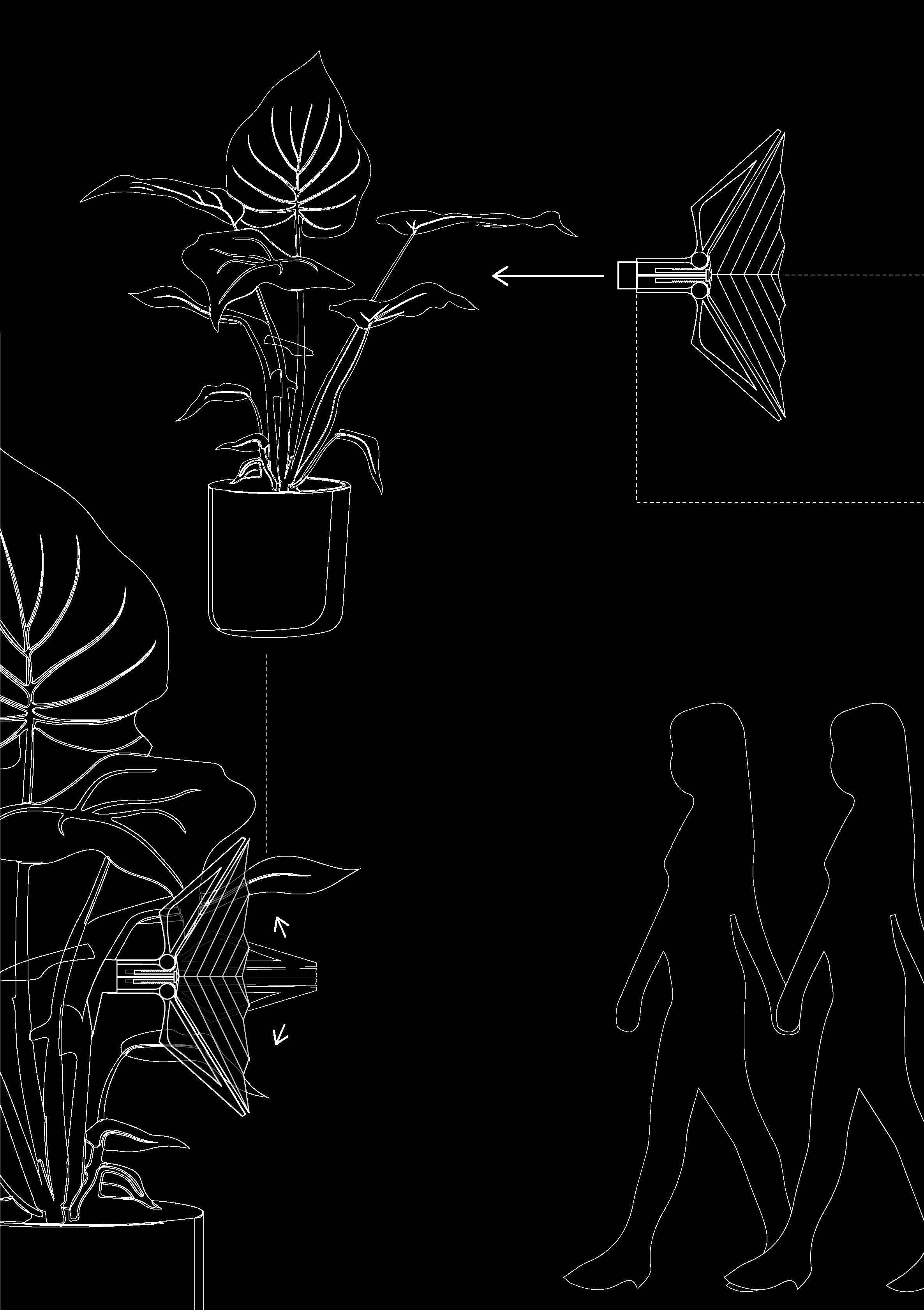

CONSTRUCTION
• Individually researched and developed 12 prototype flower petal designs at 1:1
• Once all individual elements developed, connected the flower to the mechanisim

• Attached all lighting and second flower petal to cover the connection join
• Connected the flower mechanism to the natural plant
MATERIALS
• Plolyster fabric
• 5mm / 3mm acrylic sheet
• Acrylic screw/bolts
• Steel screw/bolts
• Arduino board
• 9 watt motor
• LED lights
• Cable ties
• Power supply
• Plants


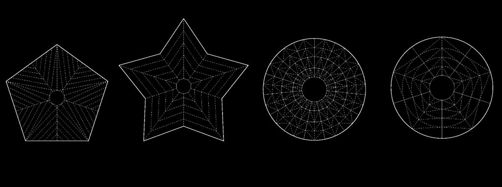
Spend time researching origami techniques, followed tutorials and learnt how orgami works. It was important to handle the fabric with care as it was easy to burn within th e creasing process. Overall completed 12 prototypes.
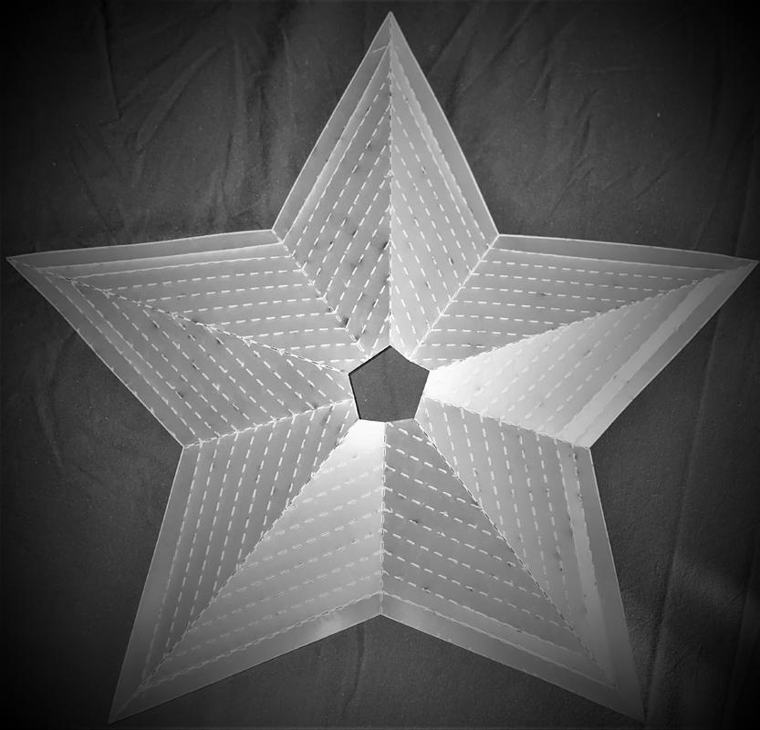
01. The Dashed lines present each open petal, 8 petals in total. Made with chiffon fabric with is light and offers a good level of opacity, the downside because of the fabric being so light it struggled to hold its shape. Was really informative in refining my flower design moving forward.
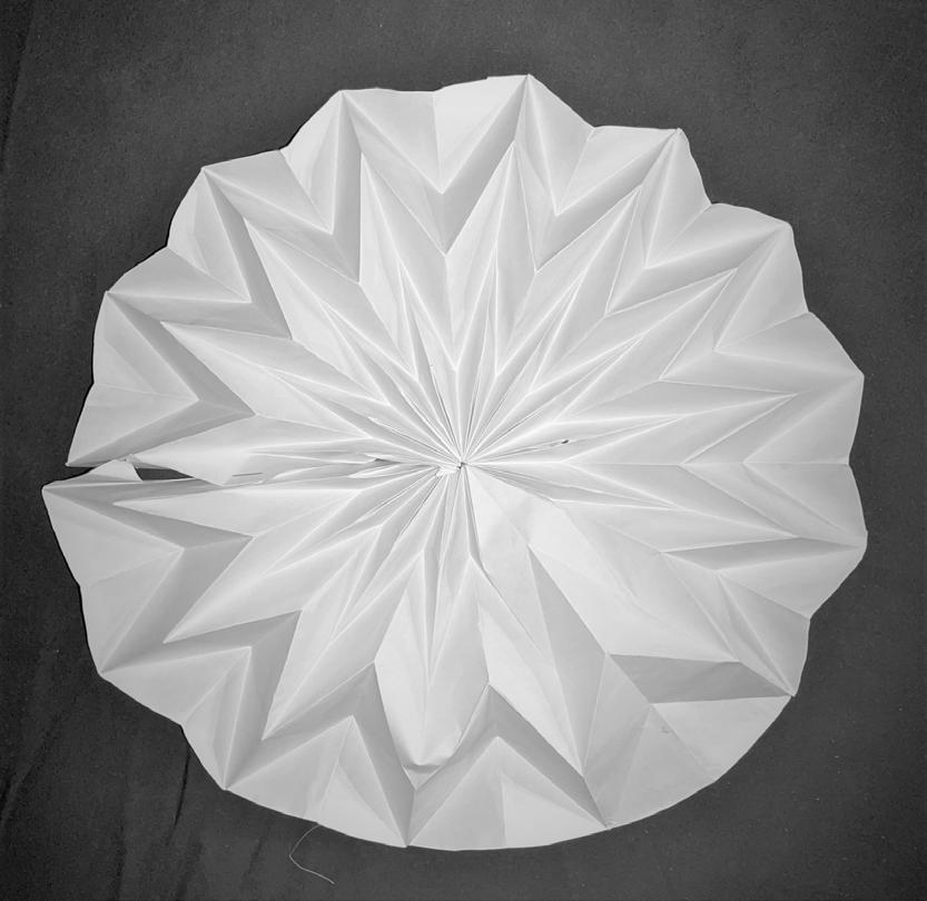
02. Once I understood how the system worked I turned my last technique into a circle form to mimic a flower. This Form worked well but the folding technique was very complex.
03.I tried the below shape and discovered that the material was too dense and didn’t allow much room for folding. In addition would require strain on the server motor once attached.
04. Through discovered 5 point circled design wouldn’t work, I developed a 5 point hexagon.
Project : Academic / 2019
Participants: Individual
Software : AutoCAD, Revit, Enscape, Adobe Photoshop
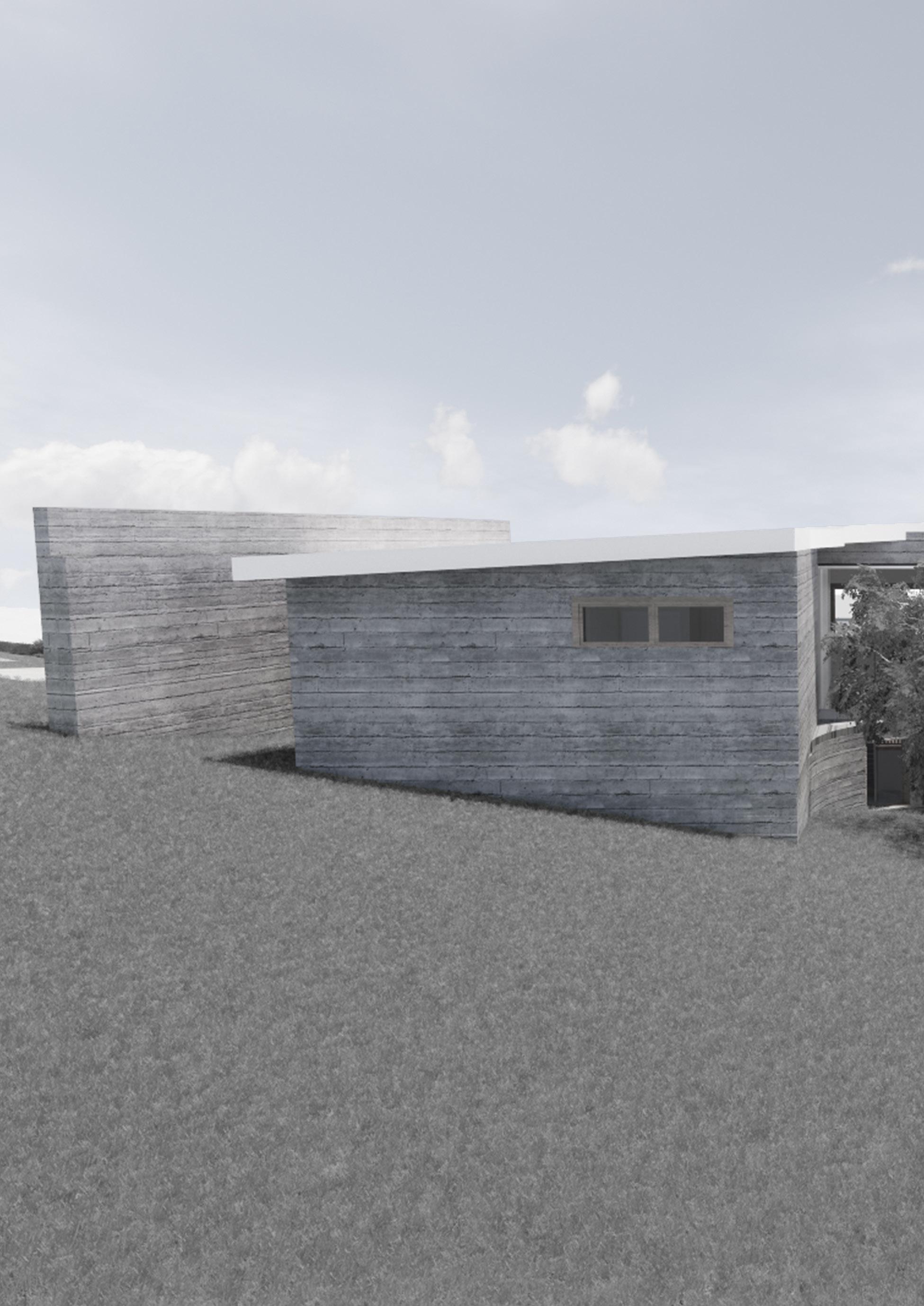
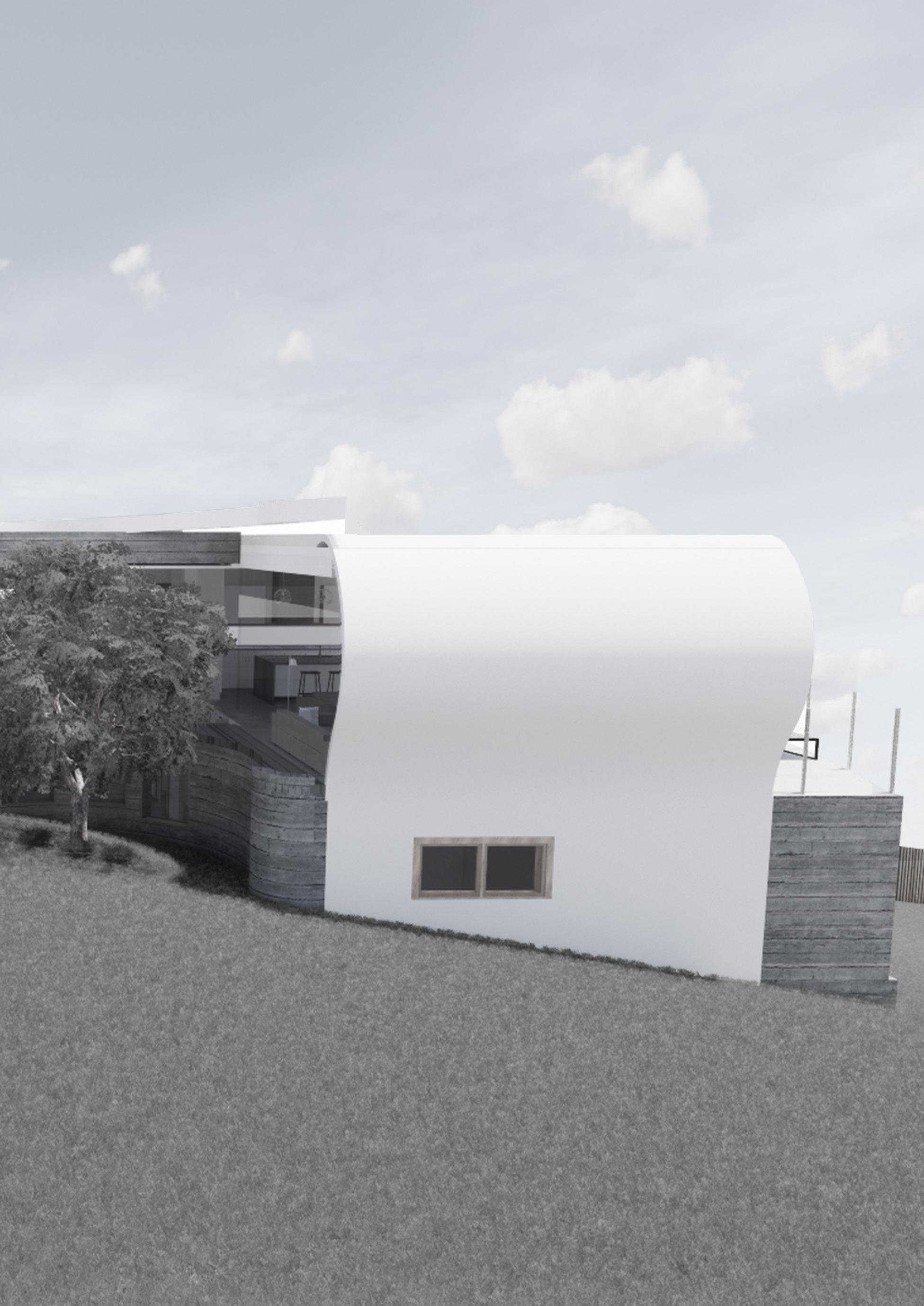
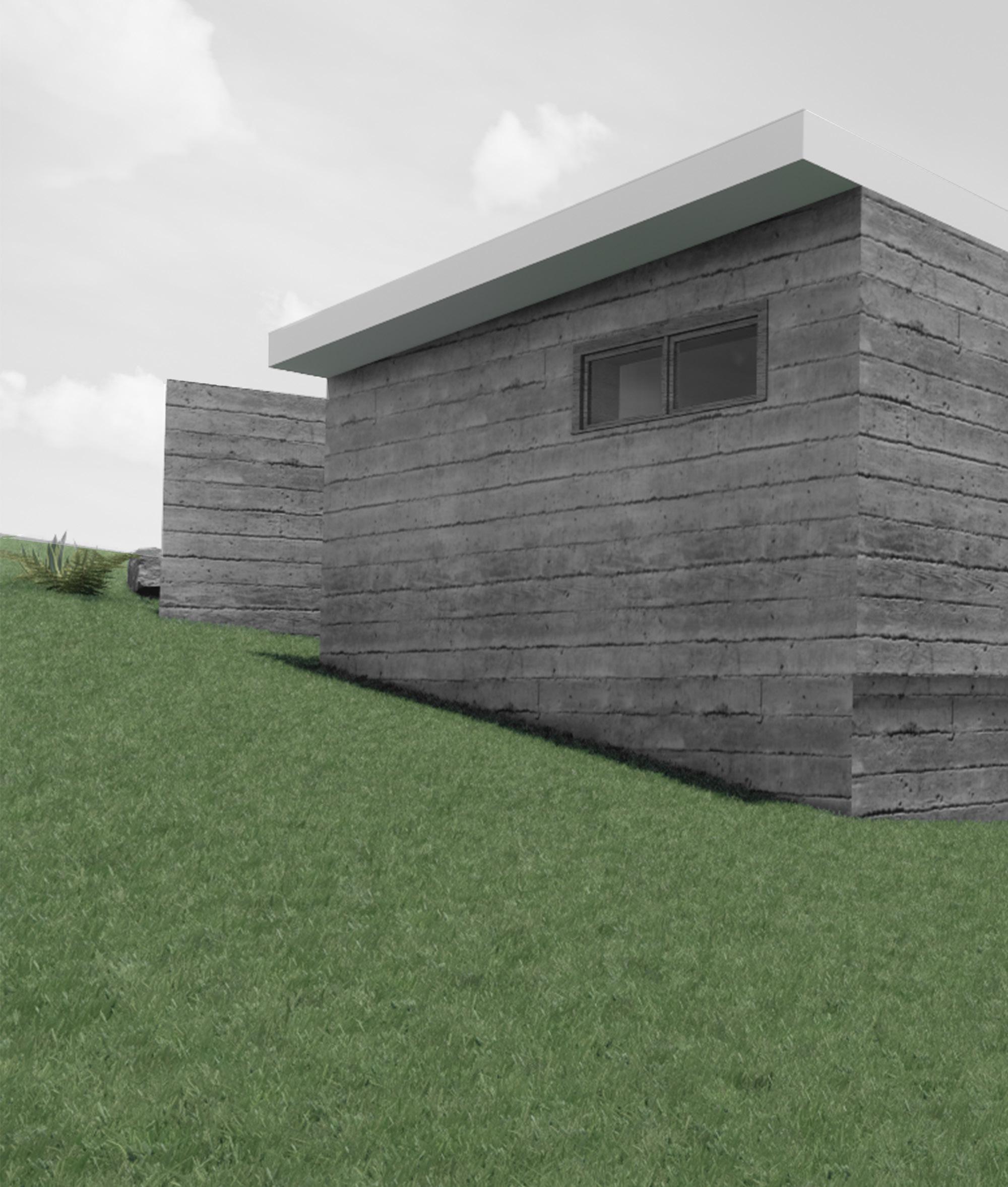
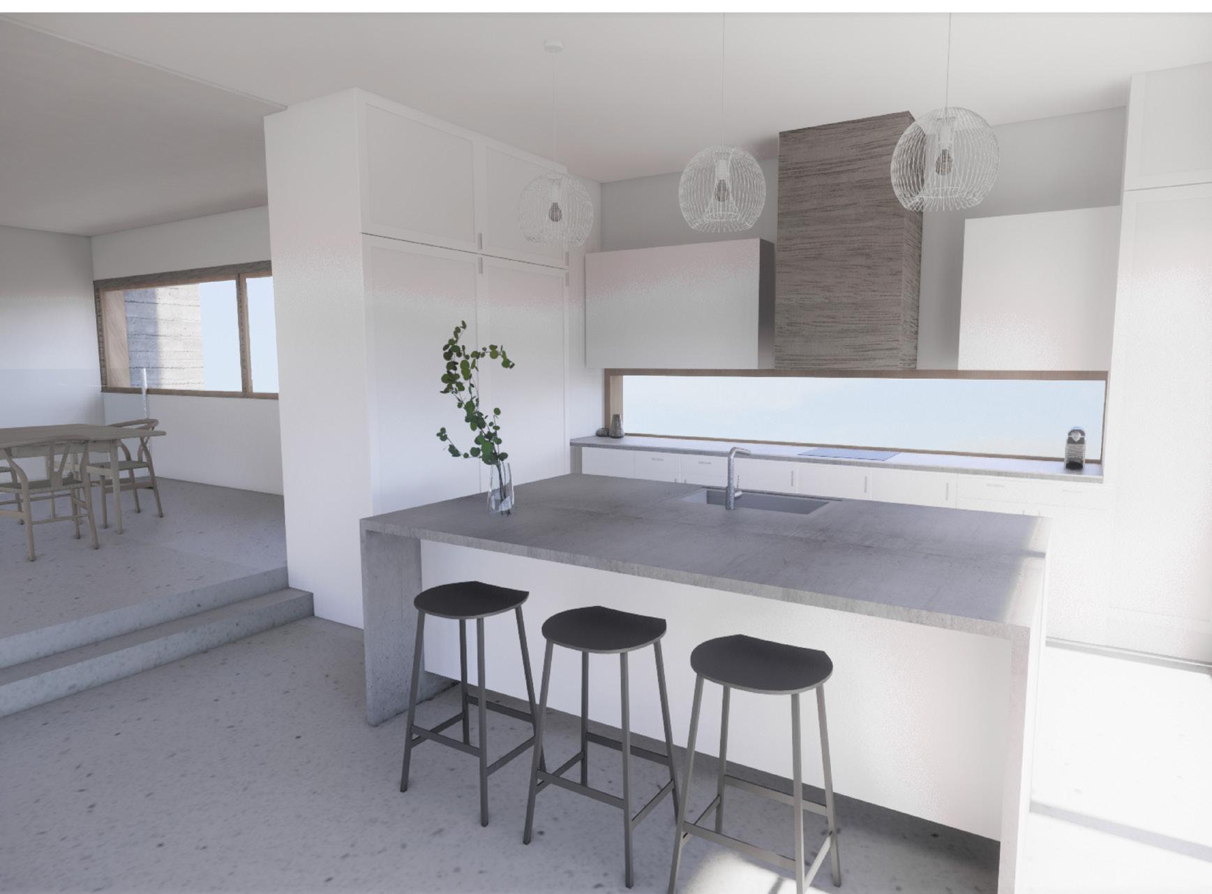
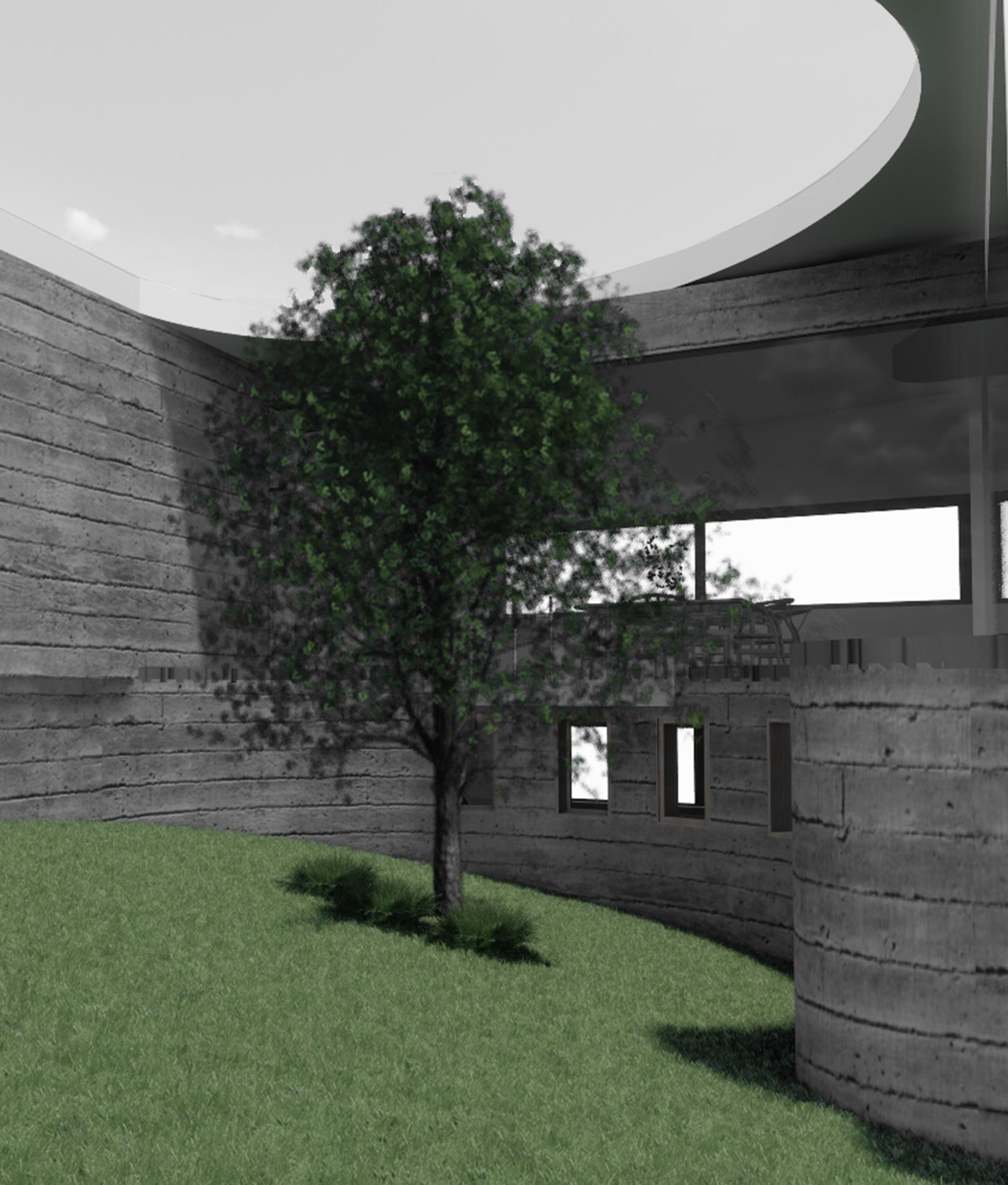
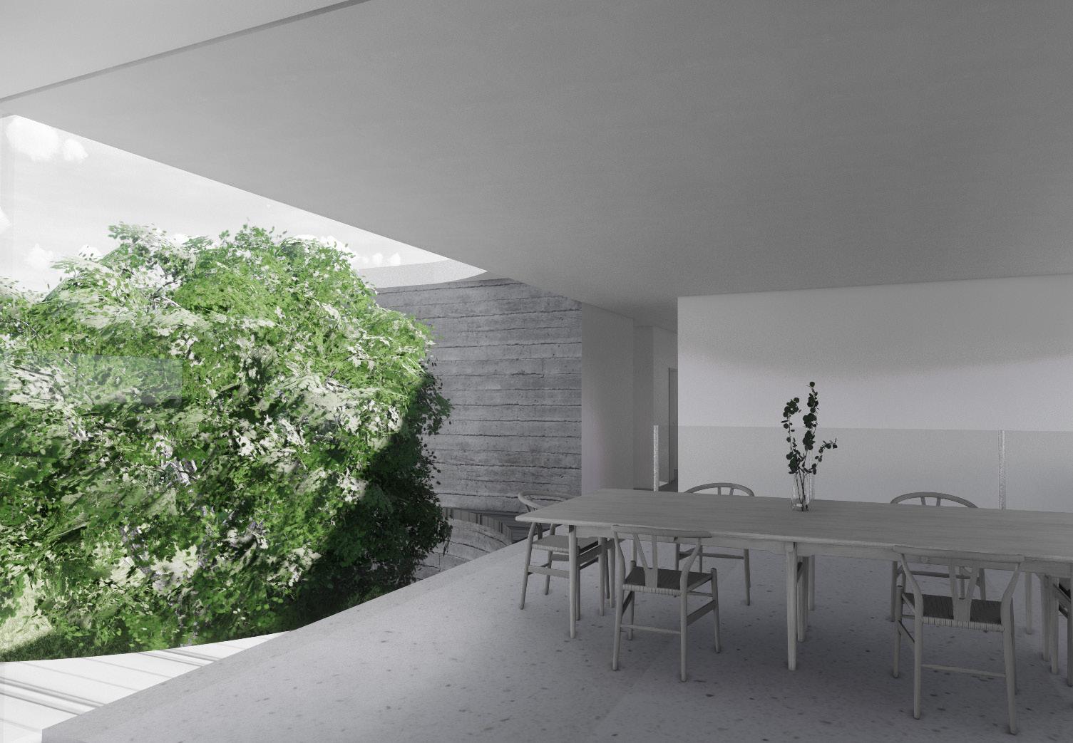
The Maple House, a three-bedroom home, designed on a sloped site with ocean views and a mature Japanese Maple Tree that was to be retained. Inspired by the curshing waves that curve around the bay. The house makes use of the japanese maple by curving around it, then an inverted curve that becomes the roof. Blending form and function. One of the added focuses was on sustainability and utilizing the natural environment, such as the ocean breeze for a passive air system and the sun for a solar heating within the home.
Project : Academic / 2020
Participants: Individual project
Software : Revit - BIM
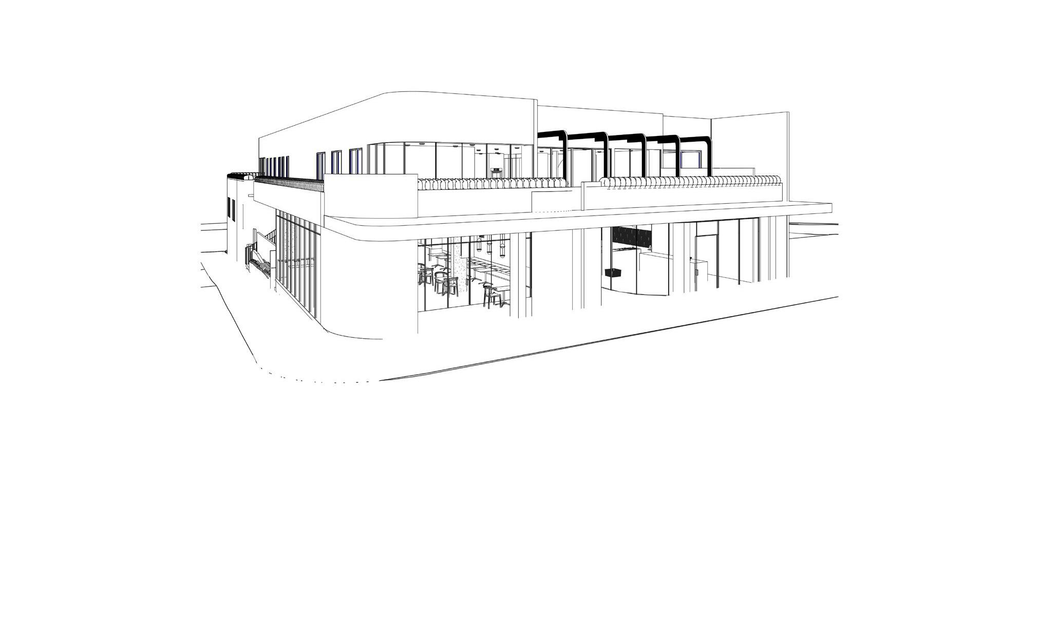
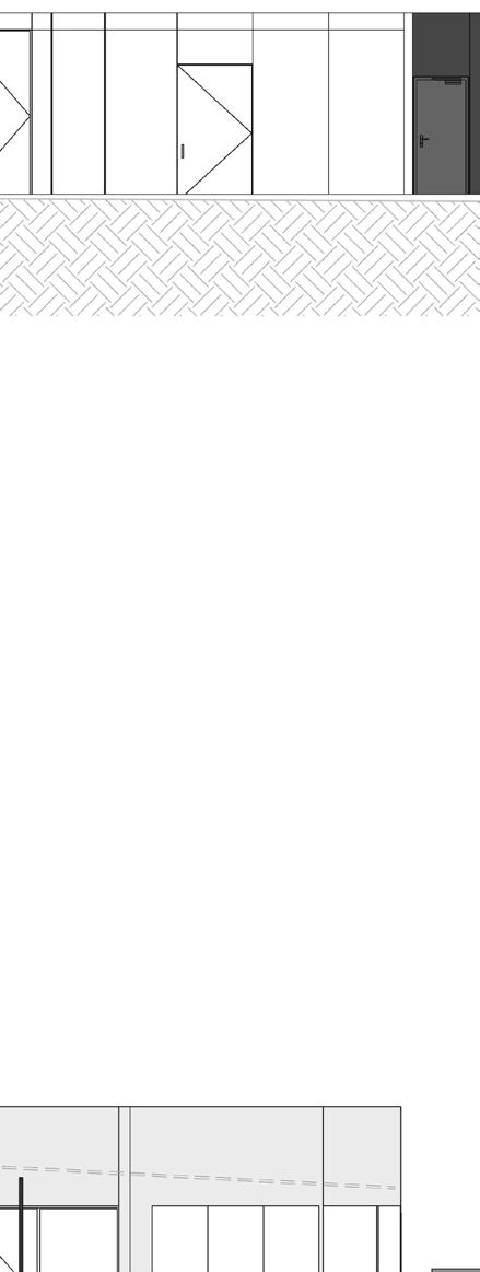
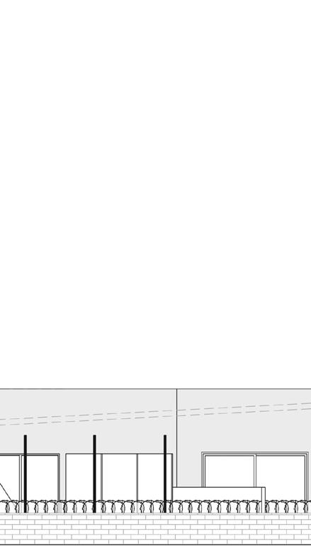
Juno is about using materiality and form to connect the built form and the natural invironment as one. Juno Development comprises of a basement carpark. Ground floor with a Café, Organic Greengrocer, Barrister’s Office, and Building Design Studio. Along with the first floor which contains two apartments each with four bedrooms. Once the schematic design was approved, further exploring materiality, sustainable and recycled material were chosen where possible. Working to the local council requirements, feasibility reports and town planning drawings were produced with all relevant documentation.
The more detailed phase then began, producing working drawings for the Juno Development. Researching, collaborating, and working from the National Construction Code and all relevant Australian Standards to accurately detail and note the specifics of the project.


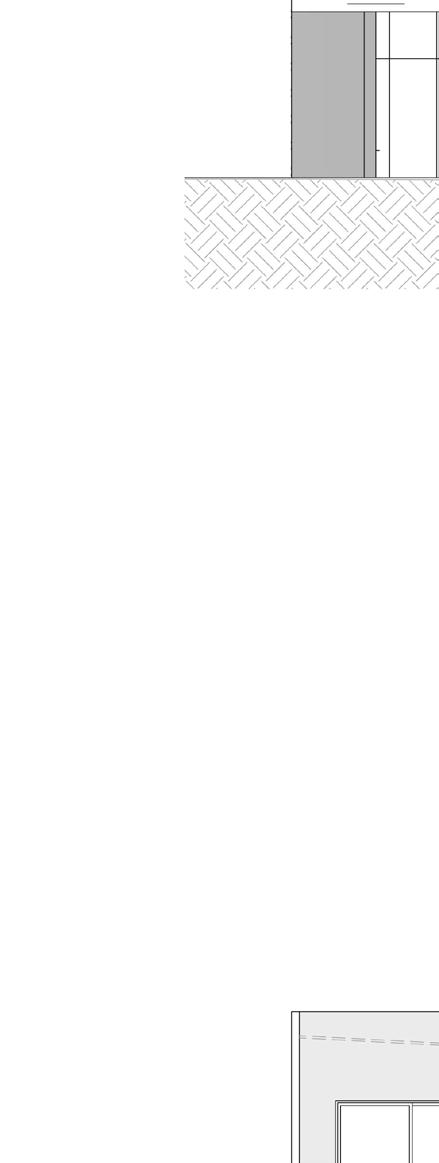

1 150mm PRECAST PANEL WALL TO ENGINEERS DETAIL AND PROVIDE 30mm OF INSULATION FIXED AND BRICK 110mm FIXED WITH BRICK TIES.
150mm PRECAST CONCRETE PANELS
(REFER TO ENGINEER'S DRAWINGS FOR DETAILS). PROVIDE BACKING RODS AND 20mm MIN DEPTH OF SILICON SEAL. AT GROUND LEVEL WALL PROFILE CHANGE TO WALL TYPE 1
PROVIDE 150mm SHOTCRETE WALL AGAINST BORED PIERS AS PER ENGINEER'S DETAILS. PROVIDE TANKING AND WEEPHOLES TO ENG. DETAIL.
150mm PRECAST CONCRETE WALL AND SELECTED FINISH. PROVIDE TANKING
UNDERGROUND -PREFER TO ENGINEER'S DRAWINGS FOR DETAILS. FRL 90/90/90
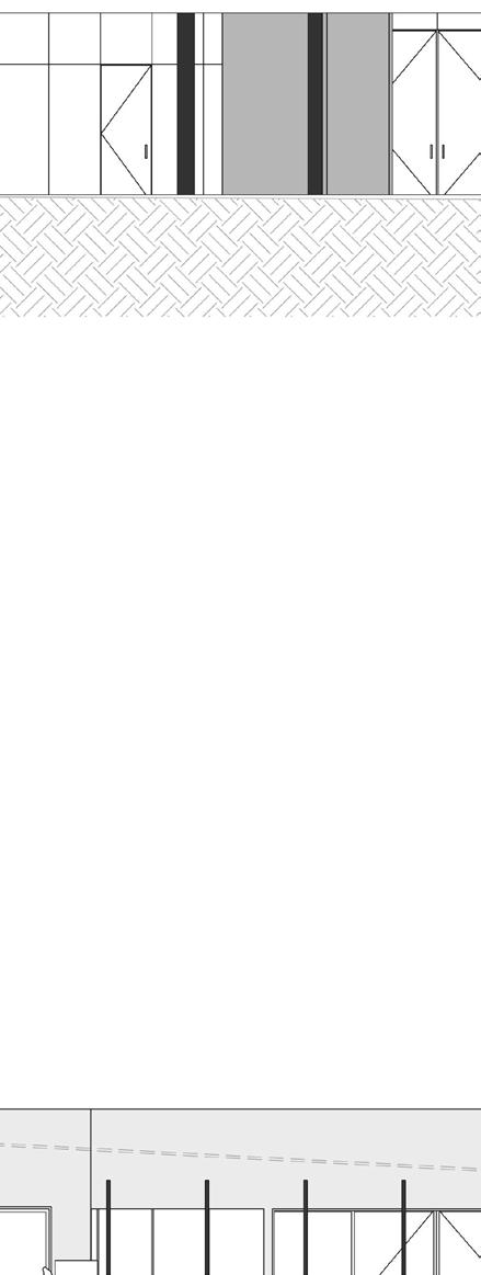
92mm STEEL STUDS @ 450 CTRS. 75mm INSULATION. 13mm PLASTERBOARD SCREW FIXED TO BOTH EXTERIOR AND INTERIOR.
NOMINAL 10mm STEEL MESH
100mm PRECAST LOAD BEARING CONCRETE WALL AS PER ENGINEER'S DETAILS. WITH SELECTED FINISH. FRL
INTERIOR.
SCREW FIXED INTERIOR.
STUD STEEL WITH 75mm INSULATION, 13mm PLASTERBOARD
10mm VENETIAN PLASTER TOWEL COLOUR TO CLIENT REQUEST
11
92mm STUD STEEL WITH 75mm INSULATION, 9mm BLUEBOARD AND 10mm RENDER IN PEARL GREY COLOUR WITH TOWEL FINISH
90mm TIMBER STUD WITH 75mm INSULATION AND 9mm BLUEBOARD
SCREW FIXED. 10mm RENDER POLISHED CONCRETE FINISH RENDER
150mm PRECAST CONCRETE PANELS
(REFER TO ENGINEER'S DRAWINGS FOR DETAILS). PROVIDE BACKING RODS AND 20mm MIN DEPTH OF SILICON SEAL.
ENSURE 20mm CAVITY TO INDEPENDENT 70mm STUD TIMBER @ 600 CENTRES WITH 50mm INSULATION.
13mm PLASTER BOARD FIXED TO INTERIOR.
14
10mmGYPROCK SUPERCHEK ATTACHED TO TIMBER STUDS AT 600MM MAXIMUM CENTRES WITH 75 GOLD BATTS INSULATION.
30mmSEPARATION BETWEEN FRAME AND GYPROCK SHAFT LINER PANEL.
25mm GYPROCK SHAFT LINER PANEL BETWEEN STEEL H-STUDS AT 600MM MAX CENTRES.
16MM GYPROCK FYRCHEK SCREW
LAMINATED TO SHAFTLINER. 30mm SEPERATION BETWEEN FRAME AND GYPROCK FYRCHEK. TIMBER STUDS AT 600MM MAXIMUM CENTRES WITH 75 GOLD BATTS INSULATION ATTACHED TO 10mmGYPROCK SUPERCHEK.
DOUBLE 110MM BRICK WALL WITH 20MM CAVITY WITH REINFORCING BARS (REFER TO ENGINEER'S DRAWINGS FOR DETAILS)
90mm TIMBER STUD WALL WITH 13mm PLASTERBOARD DRAWN
CT COOKTOP DP DOWNPIPE
DW DISHWASHER SPACE
FEDFIRE ESCAPE DOOR
FH FIRE HYDRANT
LBWLOAD BEARING WALL
F.F.LFINISHED FLOOR LEVEL
REF FREFRIDGERATOR SPACE
RF GROUND FLOOR ROOF
WF WINE REFRIDGERATER
ALL DIMENSIONS TO BE TAKEN IN PREFERENCE
THESE DRAWINGS SHALL BE READ IN STRUCTURAL ENGINEERS AND ALL OTHER DRAWINGS AND IN CONJUNCTION WITH SPECIFICATIONS AND MANUFACTURER'S
N O T E S:
ALL COLUMNS ARE SETOUT ON CENTRELINK OTHERWISE NOTED AS PER ENGINEERS
CURVED WALLS HAVE A RADIOS OF 250mm OTHERWISE SPECIFIED.
ALL WET AREAS SHALL HAVE A TILE FLOOR. ALL BEDROOMS AND WIR SHALL HAVE ALL LIVING AREAS/TERRACE TO HAVE FLOORING.
A STAIRWAY MUST HAVE NOT MORE THAN 2 RISERS IN EACH FLIGHTAND
A GOING (G) RISER (R) AND QUANTITY WHERE A RISER MUST BE WITHIN MAX: 190mm MIN: 115mm WHERE A GOING SHALL BE WITHIN MAX: 335mmMIN:250mm WITH A MINIMUM LANDING OF 750mm
LIFT DOORS MUST HAVE AN F.F.L OF 1735.11
ALL INTERNAL DOORS 1000 X 2400mm SPECIFIFED. FIRE ESCAPE DOORS TO ALL DOORS WITHIN AN EXIT PATH MUST WITHIN WITHOUT A KEY BY A SINGLE ACTION OR PUSHING DEVICE LOCATED FROM FLOOR LEVEL. EXIT DOORS MUST SWING AGAINST TO BE CAPABLE OF BEIND HELD IN AN ALL INWARD SWINGING DOORS WITHIN PAN MUST BE FITTED WITH REMOVABLE
THE DOOR TO A TOILET IS TO OPEN OR HAVE HINGES THAT ARE EASILY REMOVED OUTSIDE IF THERE IS LESS THAN 1200mm CLOSET PAN AND THE NEAREST PART FLASH ALL SANITARY FIXTURES. SEAL FLOOR JUNCTIONS WITH PVC ANGLE ALL WET AREAS USE 10mm MOISTURE PLASTERBOARD WITH SELECTED PAINT WATERPROOFING OF ALL WALLS AND SHALL COMPLY WITH CURRENT AUSTRALIAN 3740.
THERMAL INSULATION BE PROVIDED PART 5 OF THE BCA
ALL TIMBER FRAMING TO COMPLY WITH STANDARD AS: 1684 NATIONAL TIMBER
ALL FURNITURE IS FOR DISPLAY PURPOSES
RETAINED SOIL INNER FACE
SUSPENDED CONCRETE SLAB 150mm
REFER TO ENGINEERS DRAWINGS AND SCHEDULES AND ALL OTHER CONSULTANTS' DRAWINGS AND IN CONJUNCTION WITH ALL TECHNICAL SPECIFICATIONS AND MANUFACTURER'S INSTRUCTIONS.
SLAB EDGE BEAM (1400mmX150mm) AS PER ENGINEERS SPECIFICATIONS
REFER TO GENERAL NOTES ON WD001
REFER TO ENGINEERS DRAWINGS AND SCHEDULES AND ALL OTHER CONSULTANTS' DRAWINGS CONJUNCTION WITH ALL TECHNICAL SPECIFICATIONS AND MANUFACTURER'S INSTRUCTIONS. REFER TO GENERAL NOTES ON WD001
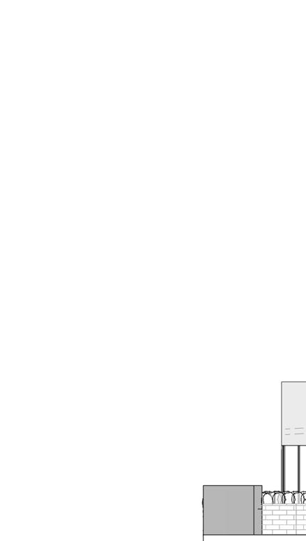
150mm CONCRETE TILT PANEL WALL APPLIED WATERPROOF MEMBRANE BELOW GROUND
100mmX50mm NYLEX VERTICAL CORE DRAINAGE LAYER BEHIND WALL AT INTERVALS SPECIFIED BY ENGINEER
50mmD x100mmW SPOON DRAIN TO PERIMETER. DRAPE SLAB REINFORCEMENT TO MAINTAIN COVER
150mmCONCRETE SLAB ON GROUND. REFER TO SCHEDULE FOR DETAILS INC REINFORCEMENT
150mm CONCRETE CAST-INSITU SLAB AS PER ENGINEER'S SPECIFIFCATIONS
150mm CONCRETE CAST-INSITU SLAB AS PER ENGINEER'S SPECIFIFCATIONS
50mm PACKING SAND
(1400mmX150mm) AS SPECIFICATIONS
PANEL WALL MEMBRANE
VERTICAL CORE WALL AT ENGINEER
150mm CONCRETE CAST-INSITU SLAB AS PER ENGINEER'S SPECIFIFCATIONS
150mm CONCRETE CAST-INSITU SLAB AS PER ENGINEER'S SPECIFIFCATIONS
STRIP FOOTING (1200mmX1200mm). REFER TO ENGINEERS DESIGN
SLAB EDGE BEAM AS PER ENGINEER'S SPECIFICATION
SLAB EDGE BEAM AS PER ENGINEER'S SPECIFICATION
TILT PANEL RETAINING WALL AND BASEMENTCONCRETE SLAB 1
TILT PANEL RETAINING WALL AND BASEMENT CONCRETE SLAB
: 20
PRECAST CONCRETE PANEL 150mm
PRECAST CONCRETE PANEL 150mm
POUR LIQUID GROUT AT 1:1 SAND AND CREMENT MIX AFTER FINAL PANEL ALIGNMENT FINISH PATCH IF REQ.
POUR LIQUID GROUT AT 1:1 SAND AND CREMENT MIX AFTER FINAL PANEL ALIGNMENT FINISH PATCH IF REQ.
DRAIN MAINTAIN
LANDSCAPING IS TO FALL AWAY FROM STRUCTURE
LANDSCAPING IS TO FALL AWAY FROM STRUCTURE
32mmW x 200mmL GROUT TUBE
32mmW x 200mmL GROUT TUBE
SCHEDULE FOR
REINFORCING BARS AS PER SCHEDULE
REINFORCING BARS AS PER SCHEDULE
10mm EXPANDATION JOIN
CONCRETE CAST-IN-SITU SLAB 150mm
CONCRETE CAST-IN-SITU SLAB 150mm
0.2 POLYETHYLENE MOISTURE BARRIER
0.2 POLYETHYLENE MOISTURE BARRIER DRILLED HOLE 24mm DIA
N20x300mm DOWEL (HOT DIPPED GAL) 150mm MIN IMBEDMENT INTO SLAB
N20x300mm DOWEL (HOT DIPPED GAL) 150mm MIN IMBEDMENT INTO SLAB
AMENDMENTS DATE (1200mmX1200mm). REFER
USE OF 15MPA BINDING CONCRETE IS PERMISSABLE TO ACHIEVE FOUNDATION DEPTH AS REQUIRED IN GEOTECHNICAL REPORT
USE OF 15MPA BINDING CONCRETE IS PERMISSABLE TO ACHIEVE FOUNDATION DEPTH AS REQUIRED IN GEOTECHNICAL REPORT
50mm PACKING SAND
NON SHRINK GROUT
50mm PACKING SAND
PROJECT NAME:
NON SHRINK GROUT
N12 STARTER BARS AT 600mm CENTRES AS PER ENGINEER'S SPECS
N12 STARTER BARS AT 600mm CENTRES AS PER ENGINEER'S SPECS
REINFORCEMENT AS PER SCHEDULE
REINFORCEMENT AS PER SCHEDULE
1153-1157 BURKE ROAD,
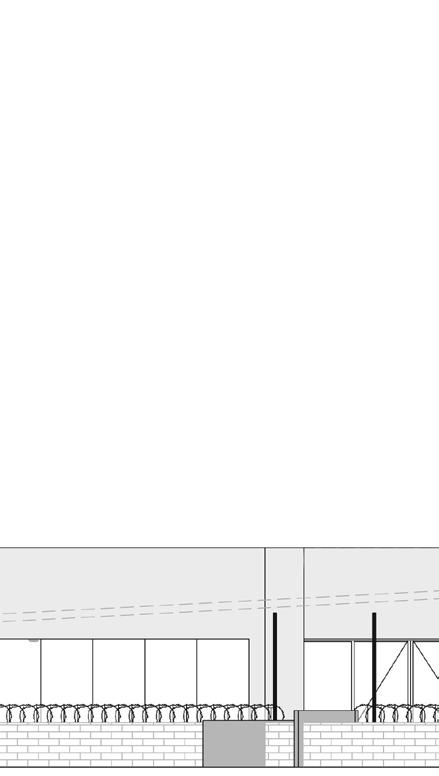
PROVIDE TWO SETS OF LIGATURES AT TOP AND BOTTOM LAP SUSPENDED
IN SITU COLUMN (600mmX300mm). REFER TO SCHEDULE FOR DETAILS
BAND BEAM 2400mmW X 150mmHAS PER ENGINEERS SPECIFICATIONS
BAND BEAM 2400mmW X 150mmHAS PER ENGINEERS SPECIFICATIONS
150MM CONCRETE SLAB ON GROUND. REFER TO SCHEDULE FOR DETAILS INC REINFORCEMENT
WATERPROOF MEMBRANE
REF COLUMN SCHEDULE FOR TIE SPACING
PROVIDE TWO SETS OF LIGATURES AT TOP AND BOTTOM LAP
THROUGHLY SCABBLE FACE
CRANK BARS 1:6 MAX. PROVIDE 2 SETS OF LIGATURES AT CRANK
PROVIDE TWO SETS OF LIGATURES AT TOP AND BOTTOM LAP
IN SITU COLUMN (600mmx300mm). REFER TO ENGINEER'S SCHEDULE FOR DETAILS
REFER TO ENGINNER'S COLUMN SCHEDULE FOR TIE SPACING
PROVIDE TWO SETS OF LIGATURES AT TOP AND BOTTOM LAP
STARTER BARS TO MATCH SIZE OF SPACING OF COLUMN BARS
PROVIDE 10mm ABEFLEX AROUND COLUMN
MASS PAD FOOTING (1500mmx750mm)
REFER TO ENGINEERS PLAN AND SCHEDULE FOR DETAILS
NO DRAINAGE OR SURFACE TRENCHESTO BE LOCATED BELOW THIS LINE
Project : Academic / 2022
Participants: Group of 4, displaying only individual drawings and design
Software : Rhino, Enscape, Adobe Photoshop, Adobe Illustrator
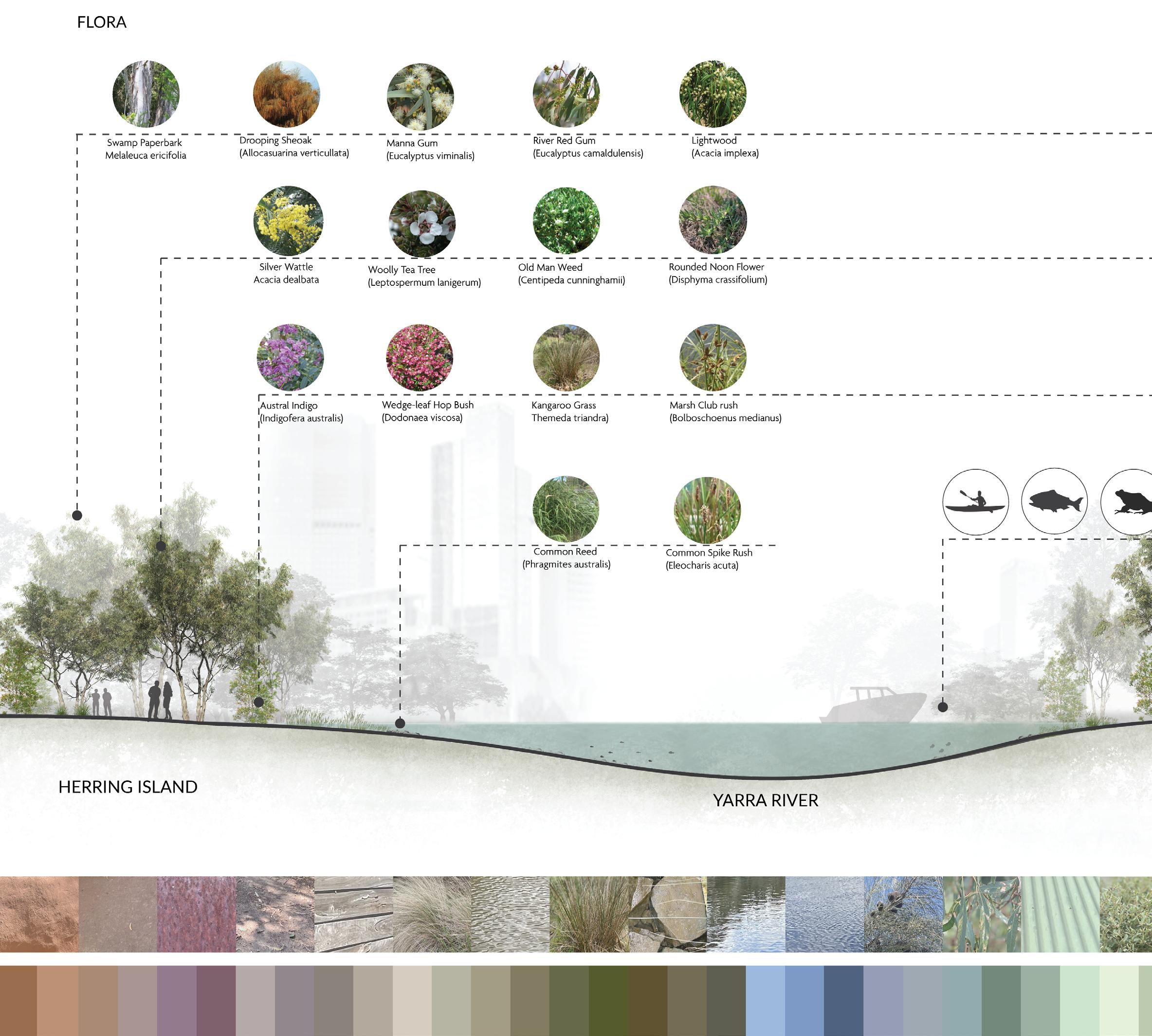
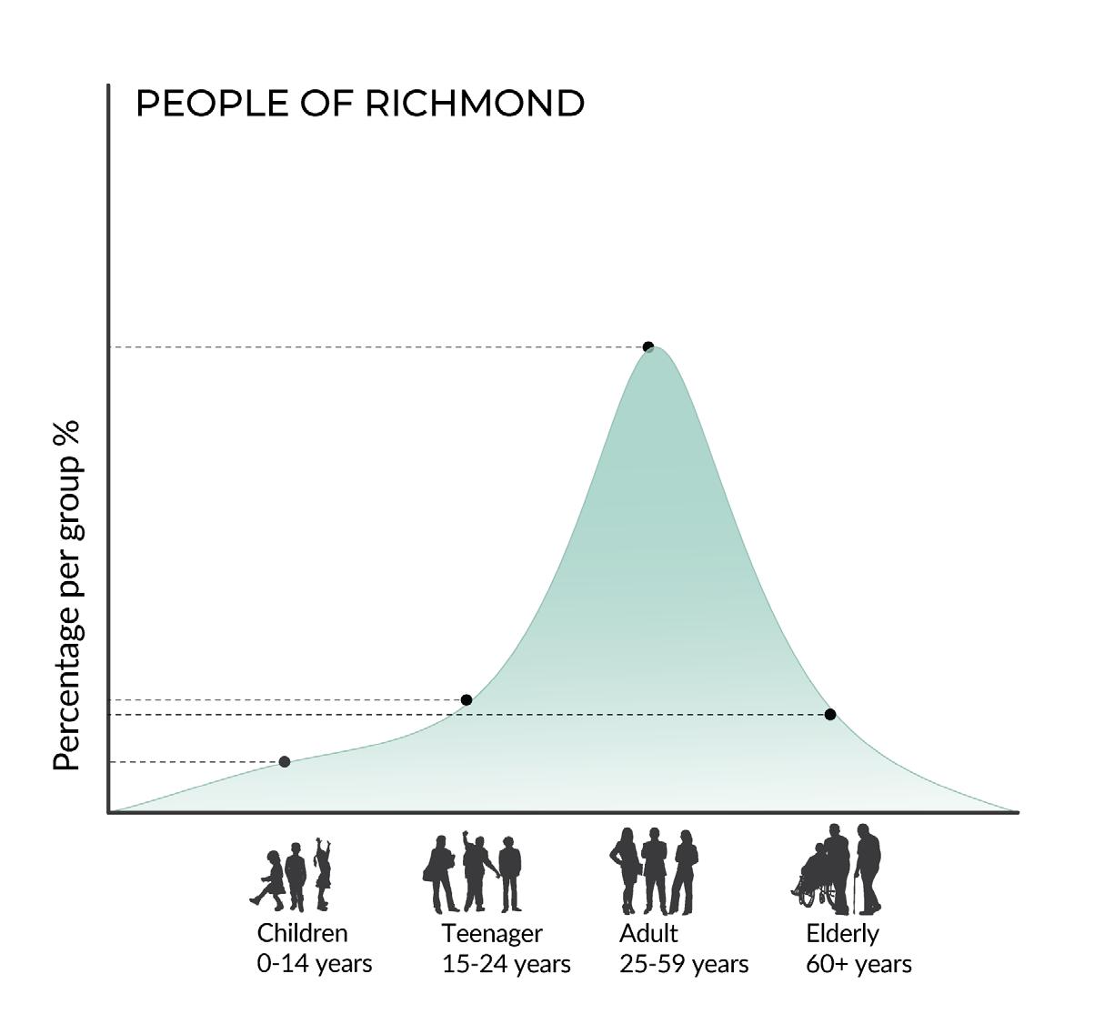
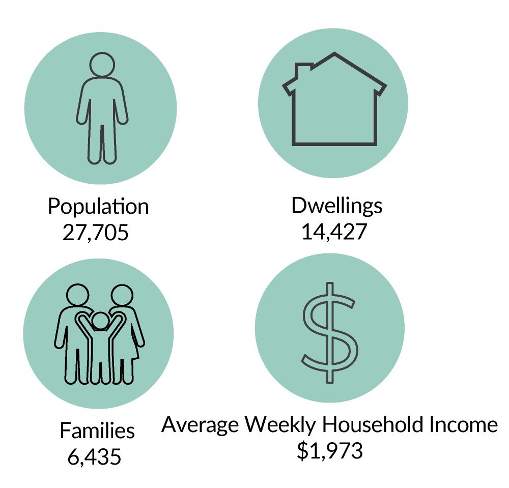
A water and nature boundary between Richmond and South Yarra, separated by a river but forgotten about since it’s creation. Once man made but now stands juxtaposed to the concrete and industrial heritage of Richmond. A way to access Herring Island from Richmond and connect the land but to emphasise the duality between the natural and the created.
Earth Dock is about reconnecting people to herring island and undoing the man-made channel running through the north side.
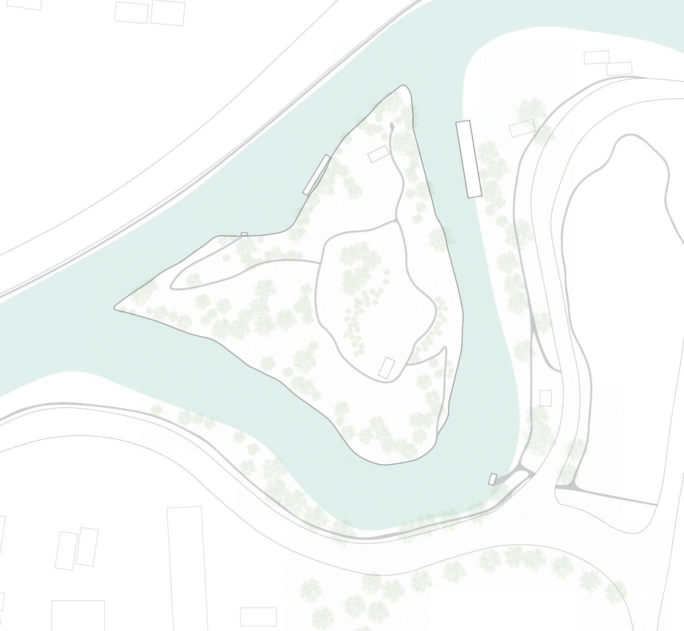
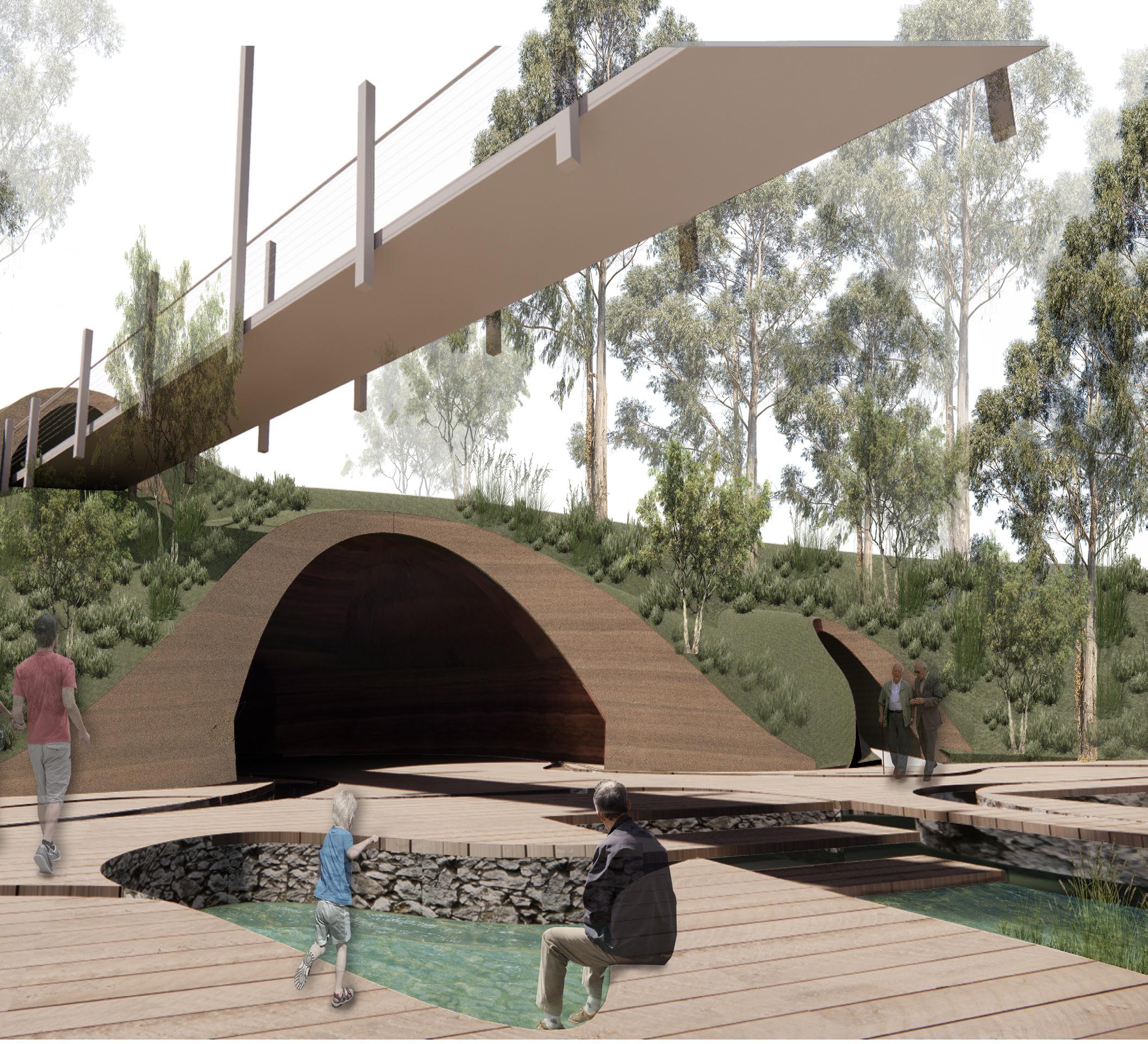

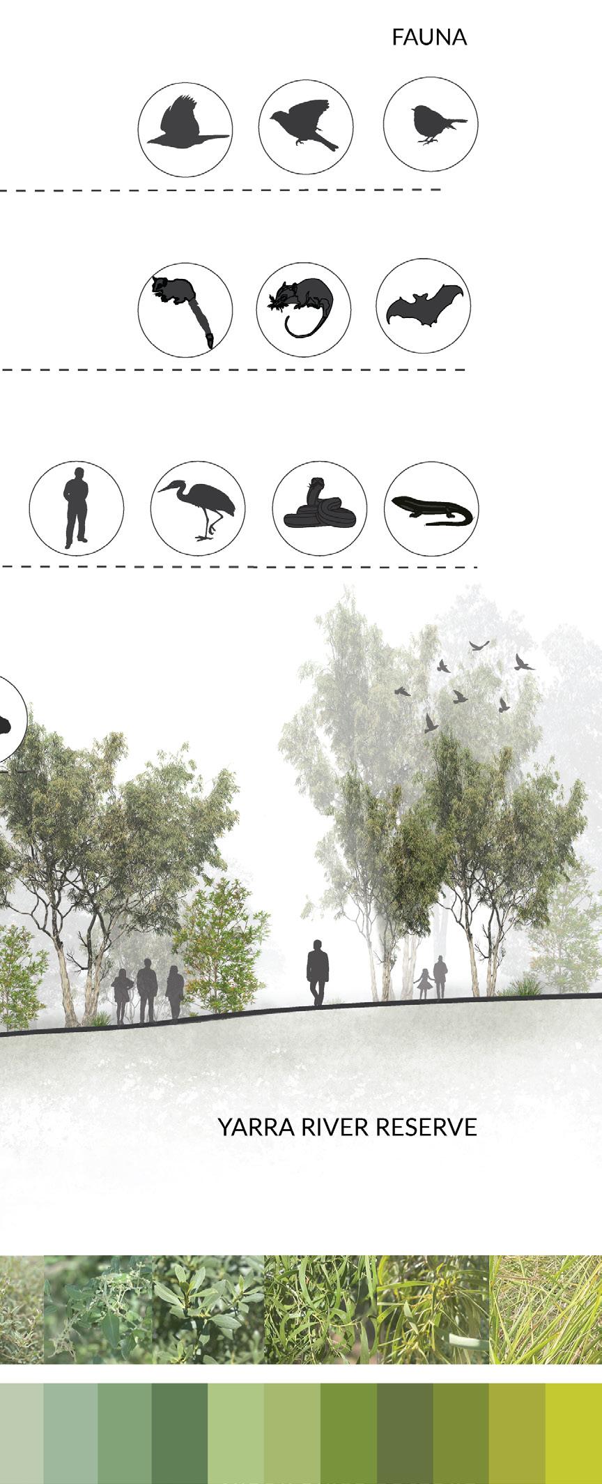
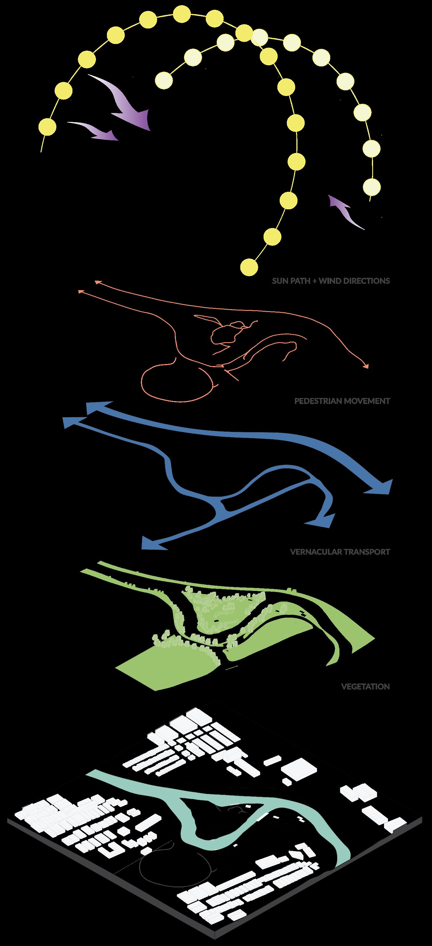
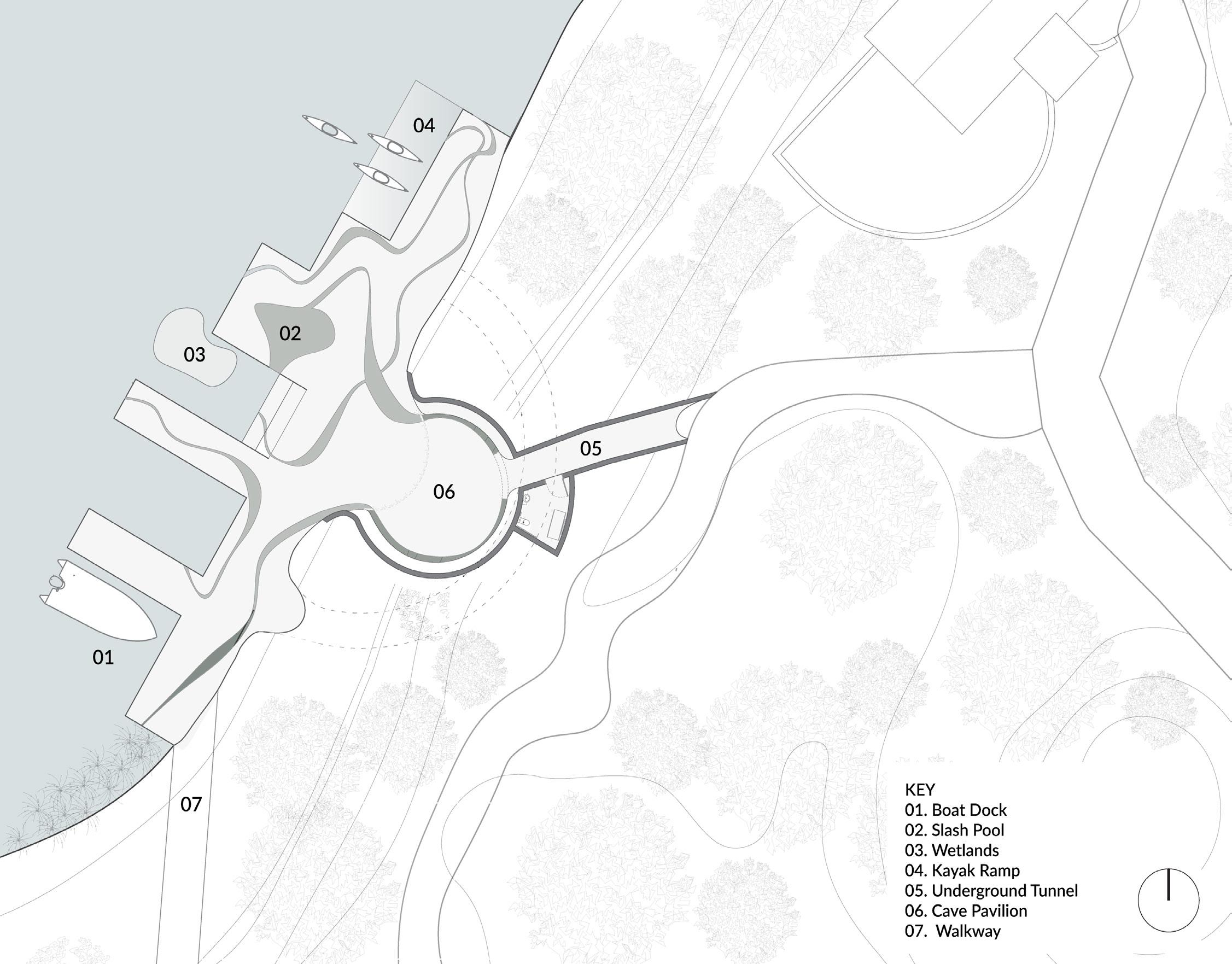
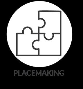


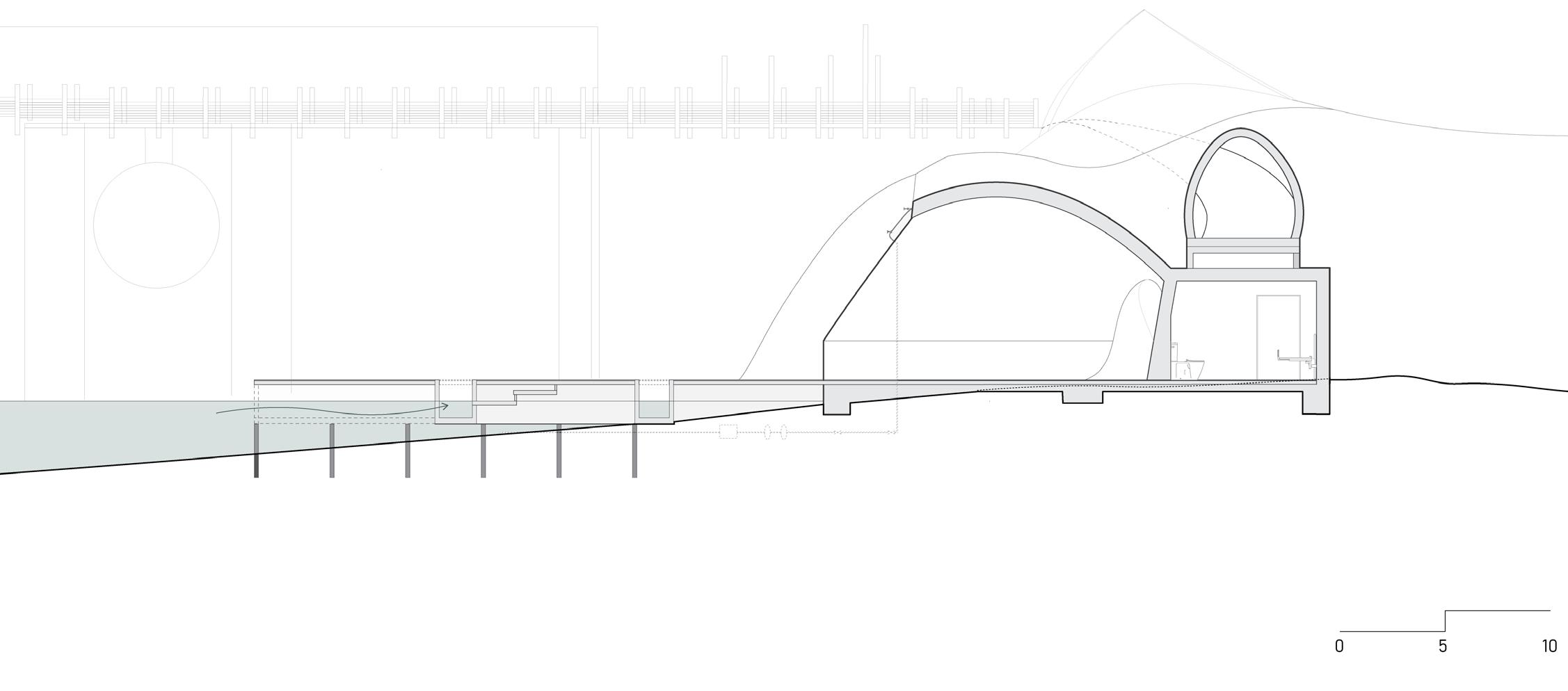
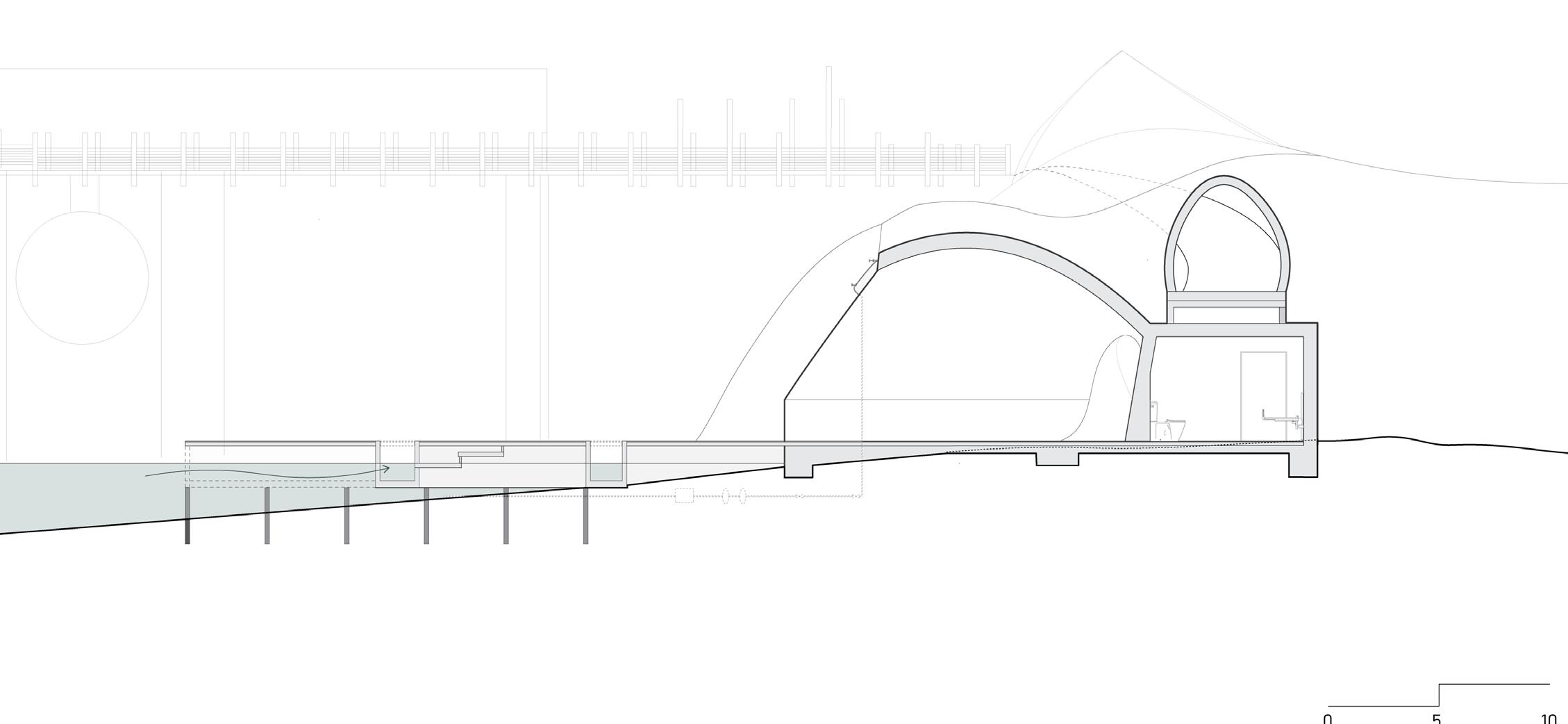
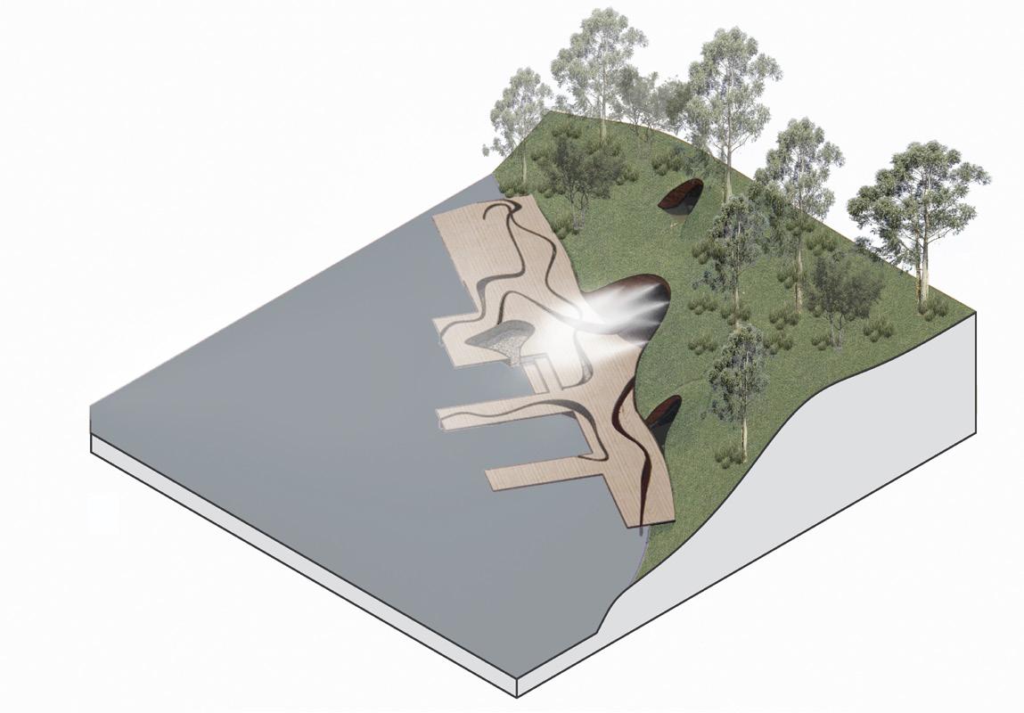
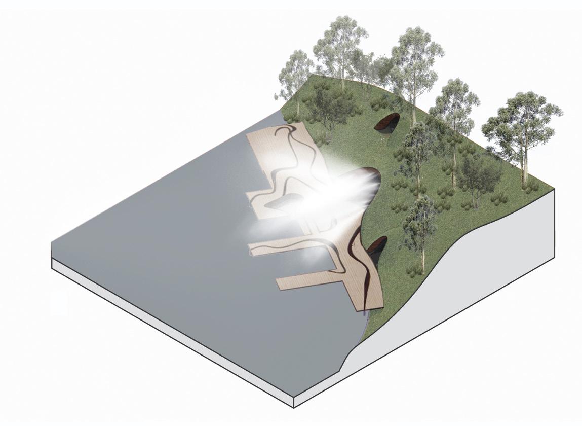
Connecting people back to water through river channels across the dock. These channels are various depths in order for the rising and falling tide to create a sensory experience. Using rock taken from the existing waters edge as the base structure creates a larger sound experience, emulating nature.

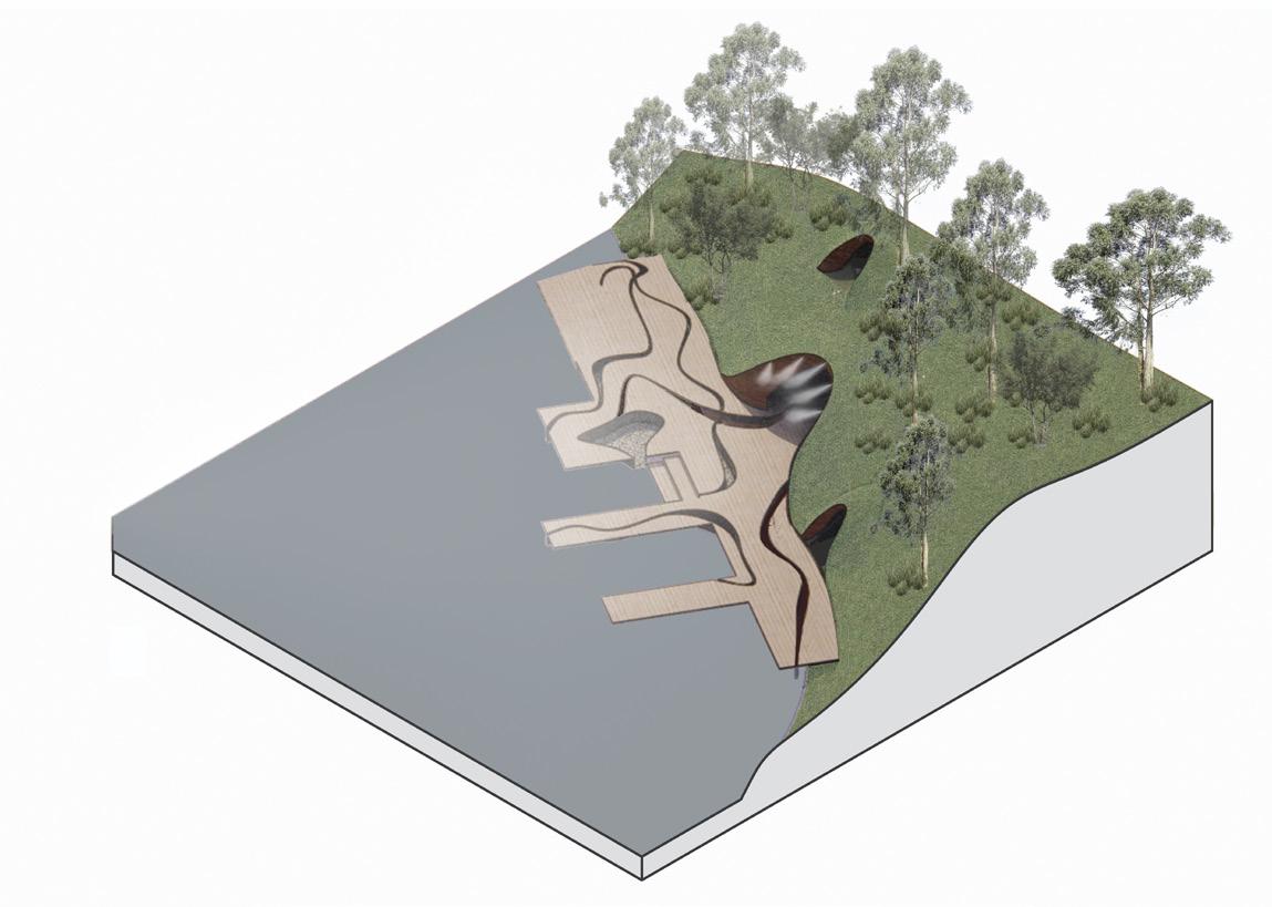
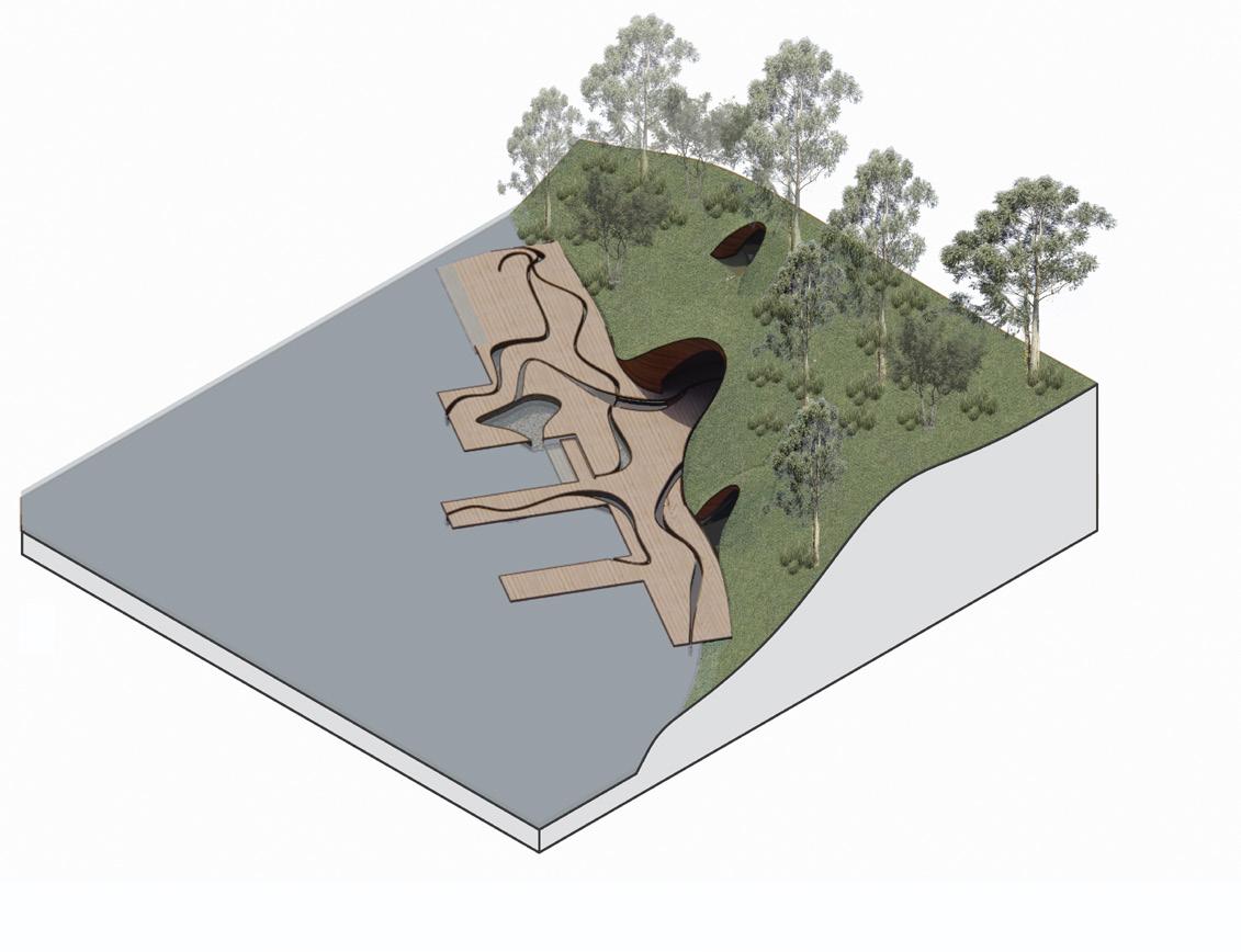
The second aspect having mist nozzles at the opening on the underground pavilion. This mist is released when the water bridges ‘closes‘ as a signal to people to leave the island as the land needs to regenerate. This mist will also aid to hide the dock and earth pavilion and create a non place experience.
0432512992
amypcollins.01@gmail.com in/amy-collins-240929104/ Melbourne, Victoria