


EXPERIENCE
ARCHITECTS LOFT - PHOENIX, AZ (REMOTE)
NOVEMBER 2022 | CURRENT
POSITION: Project Manager
DUTIES:

• Oversaw entire projects from design concept to construction completion
• Developed + tracked project schedules and timelines
• Prepared project proposals and bid requests for all required trades throughout a project
• Reported project progress regularly to clients, trades, + all stakeholders
• Developed + tracked project estimates throughout design + monitored budget during construction
ALEX MORGAN
ORLANDO, FL
502.523.6336
alexmorgandesign@gmail.com
EDUCATION
UNIVERSITY OF CINCINNATI - CINCINNATI, OH
College of Design, Architecture, Art, and Planning
Bachelor of Science in Architecture
Class of 2017
JEFFERSONVILLE HIGH SCHOOL - JEFFERSONVILLE, IN
Graduated with JHS Honors Diploma
Class of 2013
SOLIDWORKS
ASSOCIATE - MECHANICAL DESIGN
3D Experience Company
Awarded May 1st, 2012
SKILLS
PROFICIENT WITH:
Revit, AutoCAD, Photoshop, InDesign, Illustrator, SketchUp, Rhino3D, Chief Architect, VRay, Lightroom, Podium, Enscape3D, 3ds Max, Maya, Twinmotion, Solidworks, 20-20 Design, Procore, CoConstruct, MS Project, Adobe Acrobat, Bluebeam Revu, G-Suite, Microsoft Office Suite, Hand Drafting & Modeling
• Conducted take-offs to estimate materials needed
• Attended + led on-site meetings for design verification + oversaw on-site trades and deliveries as needed
• Met with clients to determine wants/needs in design
• Preformed on-site measurements + verifications
• Utilized BIM technology to create construction documents, including:
• As-builts (if applicable)
• Site Plans + Floor Plans
• Renderings
• MEP drawings
• Interior + exterior elevations
• Details + Sections
• Window/door/millwork schedules
• Life Safety Plans + Occupant Loads
• Created 3D visuals for design conceptualization
• Managed ASMEP drawings with consultants throughout design to ensure proper coordination
• Reveiwed QC sets and provided redlines for drafting team as needed
• Coordinated with Civil Engineers and Landscape Architects as needed
• Created + presented client presentations
• Completed zoning reveiws as needed per municipal requirements in various jurisdictions
• Prepared + submitted all required documents for preapplication submittals, HOA reviews, or city permit applications
• Attended all city design review meetings as needed
L2 STUDIOS - ORLANDO, FL
OCTOBER 2021 | NOVEMBER 2022
POSITION: Architectural Project DUTIES:
• Managed projects from concept
• Created submittal packages
• Attended + led client meetings
• Created 3D models for conceptual
• Created renderings for presentations
• Created full construction ready
• As-builts (if applicable)
• Proposed drawings
• Renderings
• MEP drawings
• Interior + exterior elevations
• Details + Sections
• Window/door/millwork
• Life Safety Plans + Occupant
• Met with engineers to coordinate construction between all disciplines
MERRILL CONSTRUCTION GROUP
JUNE 2017 | SEPTEMBER 2021
POSITION: Lead Architectural Designer DUTIES:
• Met with clients to determine
• Oversaw entire design project through construction completion
• Preformed on-site measurments
• Created full construction ready
• As-builts (if applicable)
• Site Plans + Floor Plans
• Renderings
• MEP drawings
• Interior + exterior elevations
• Details
• Window/door/millwork
• Created full scope of work documents
• Created + presented client
• Created full job books for production
• Met on site with subcontractors guidance throughout project
• Coordinated project estimation selection allowances

FL 2022 Project Manager concept to completion packages for zoning + permits meetings conceptual + final design presentations ready drawing sets, including: elevations schedules
Occupant Loads coordinate details of designs and disciplines GROUP - NASHVILLE, TN
Designer determine needs/wants project from concept design completion measurments + verifications ready drawing sets, including: elevations schedules documents presentations production team at hand off subcontractors + carpenters for design project estimation for budgets and

TABLE OF CONTENTS
PROFESSIONAL
WORKPLACE
Boutique Hotel - St. Petersburg, FL | Page 4
Hotel Design- Jupiter, FL | Page 6
Amenity Clubhouse - Deland, FL | Page 8
Clubhouse Expansion - Port St. Lucie, FL | Page 10
Hotel Design - Tampa, FL | Page 12
Plaza Design - Denver, CO | Page 14
Co-Work Facility - Denver, CO | Page 16
RESIDENTIAL
Whole House Remodel - Nashville, TN | Page 18
Kitchen Remodel - Nashville, TN | Page 22
Whole House Remodel - Nashville, TN | Page 26
Screen Porch Addition - Nashville, TN | Page 30
Second Story Addition - Nashville, TN | Page 34
Whole House Remodel - Nashville, TN | Page 36
Kitchen Remodel - Atlanta, GA | Page 38
Kitchen Remodel - Atlanta, GA | Page 40
ACADEMIC STUDIO
Row House Design | Page 42
Alaska + Canada Border | Page 44
Over-The-Rhine Housing | Page 46
HAND SKILLS
Model Making | Page 48
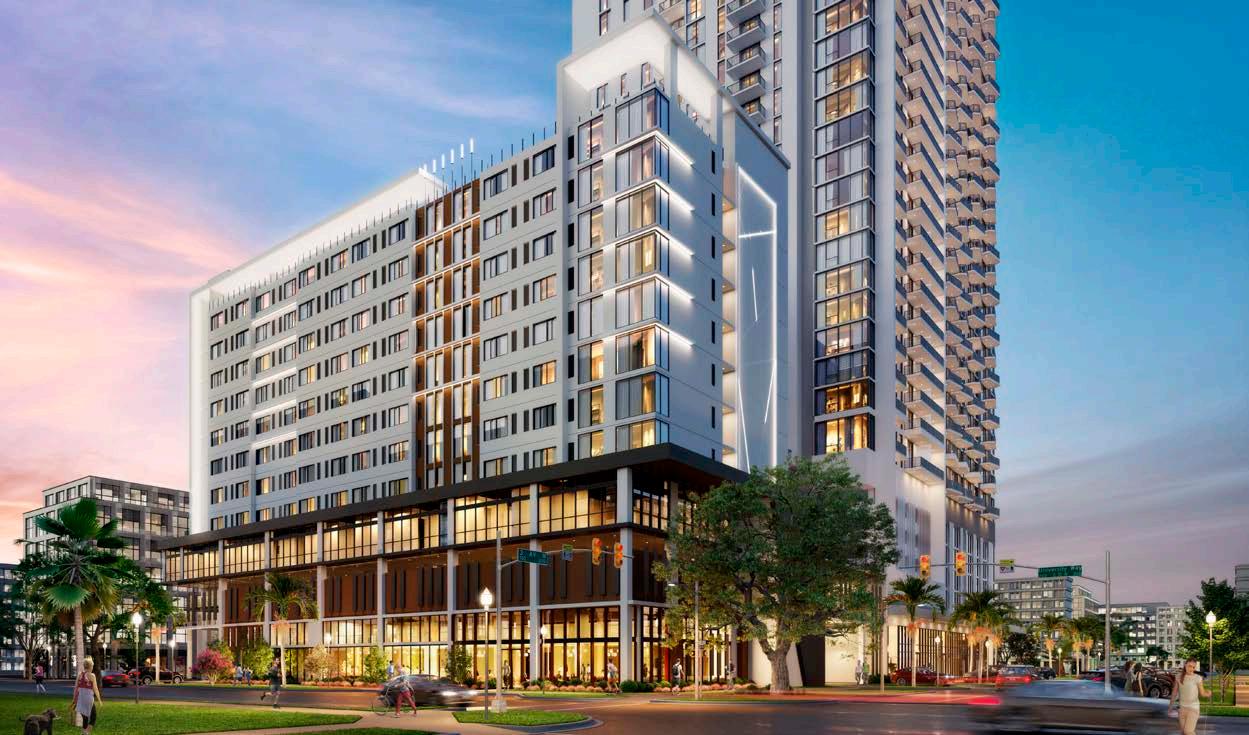
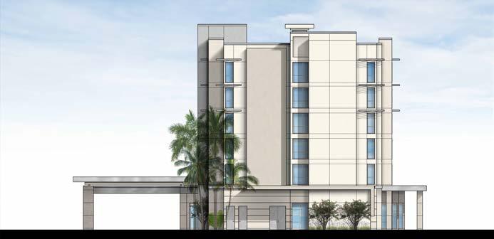
BOUTIQUE HOTEL
L2 Studios
St. Petersburg, FL
This project was for a small boutique hotel in downtown St. Petersburg Florida. The building was to share an existing site with a larger residential tower. I was tasked with coordinating the design of the two buildings to make sure they would be cohesive to each other. The design of our hotel building pulled inspiration from the rich musical history of downtown St. Pete, while also keeping in tune with the overall aesthetic of the surrounding buildings in the area.

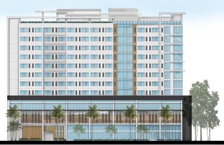
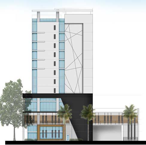
RENDERED EXTERIOR ELEVATIONS:
SKILLS:
• AutoCAD
• 3ds Max
• Adobe Photoshop
PAGE 4
EXTERIOR RENDERING:
PAGE 5 9,175 SF GROUND LEVEL HOTEL PUBLIC 30 PARKING SPACES NORTH STAIRWAY 3rd AVENUE NORTH 2nd STREET NORTH KITCHEN 1050 SF BAR TRANSFORMER FIRE COMMAND CENTER LUGGAGE FRONT DESK MANAGER FRONT DESK OFFICE GUEST ELEVATOR LOBBY FUEL BAR HARVEST KITCHEN MENS WOMENS SERVICE/STORAGE LOUNGE INFORMAL MEETING ROOM MAIN ENTRANCE SECONDARY ENTRANCE LOOK-UP ARRIVAL MOMENT REGISTRATION MARKET OUTDOOR CAFE SEATING 480 SF EV READY EV READY EV READY EV FUTURE EV FUTURE EV FUTURE EV FUTURE EV FUTURE TRASH RECYCLING A/C AREA (GROUND FLOOR) OPEN SPACE: PARKING SPACES (STD.): PARKING SPACES (CMP.): PARKING SPACES TOTAL: 9,175 SF 480 SF 94 30 124 13.8% 4' Rise 29' Run 16.5% 5'-4" Rise 32' Run 10.42% Rise Above 8.11% 4' Rise 49' Run FIRE PUMP MECH/ BOILER GENERATOR SOUTH STAIRWAY TRASH STAGING ELECTRICAL up up up PANTRY ICE WATER GUEST LAUNDRY DBL QUEEN DBL QUEEN ELECT. IDF HK STORAGE GUEST ELEV. LOBBY KING KING KING KING KING KING DBL QUEEN DBL QUEEN KING KING CONNECT CONNECT DBL QUEEN DBL QUEEN DBL QUEEN DBL QUEEN KING KING KING KING CONNECT SUITE 12,050 SF PER FLOOR 23 ROOMS PER FLOOR 184 GUEST ROOMS TOTAL 13 KING ROOMS/FLOOR (59%) 9 QUEEN/QUEEN ROOMS/FLOOR (41%) 1 SUITE/FLOOR 24 CONNECTING KING TO QUEEN/QUEEN GUEST ROOM FLOORS 12,050 SF LEVEL 4 - GUEST ROOM FLOOR PLAN 100 SF 200 SF 175 SF 325 SF ANALYSIS FOR PARKING SPACES 1 SPACE PER (4) GUEST ROOMS 184/4= 46 SPACES DBL QUEEN KING SOUTH STAIRWAY NORTH STAIRWAY up up 3,192 SF (A/C ENCLOSED) LEVEL 12 - ROOF AMENITY DECK NORTH STAIRWAY GUEST ELEV. LOBBY MECHANICAL YARD 500 SF CHEMICAL 30 SF POOL EQUIP. & ELECT. 270 SF STAGING & STORAGE 760 SF MEN'S WOMEN'S BAR SWIM/SPA 600 SF SUN LOUNGE 573 SF UNISEX NOTE ALL SOFA SEATING IS FIXED IN PLACE ANALYSIS FOR ACCESSORY USE PARKING SPACES 1 SPACE PER 500 SF (GFA) OF USE AREA 3,500 SF/500 = 7 SPACES SUN LOUNGE 500 SF LOUNGE 2465 SF JAN. TOWELS/ TRASH UNISEX SOUTH STAIRWAY MEETING 2562 SF 1-7sf Person 366 People MECH/STOR 230 SF PANTRY 500 SF GUEST ELEV. LOBBY MEN WOMEN SMALL CONF. 625 SF CIRCULATION PRE-FUNCTION 512 SF 1-7sf Person 75 People FLEXIBLE MTG. ROOMS 650 SF FITNESS 1000 SF STORAGE 6.04% PARKING RAMP 35 PARKING SPACES FLAT DECK +31' 11,500 SF LEVEL 3 - PARKING/MEETING & FITNESS FLAT DECK +23'-0" Compact FDC FDC FDC FDC STORAGE 288 SF CIRCULATION HORIZONTAL EXIT 2 HOUR RATING 91 91 92 92 OCCUPANT LOAD: WEST AREA OF HORIZONTAL EXIT: 454 PEOPLE EAST AREA OF HORIZONTAL EXIT: 124 PEOPLE SOUTH STAIRWAY F+B OFFICE SMALL CONF./ HUDDLE 280 SF KITCHEN/ CENTRAL HUB NORTH STAIRWAY up GROUND FLOOR PLAN: MEETING ROOMS + PUBLIC AREAS: TYPICAL GUESTROOM FLOOR PLAN: AMENITY ROOF PLAN:
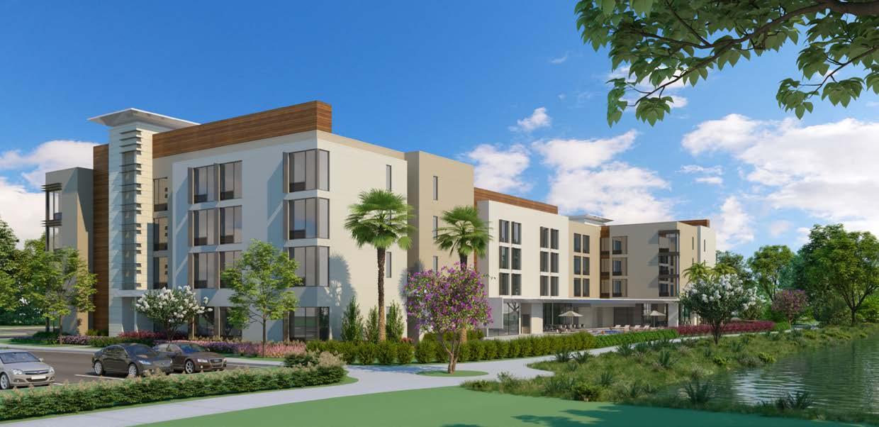
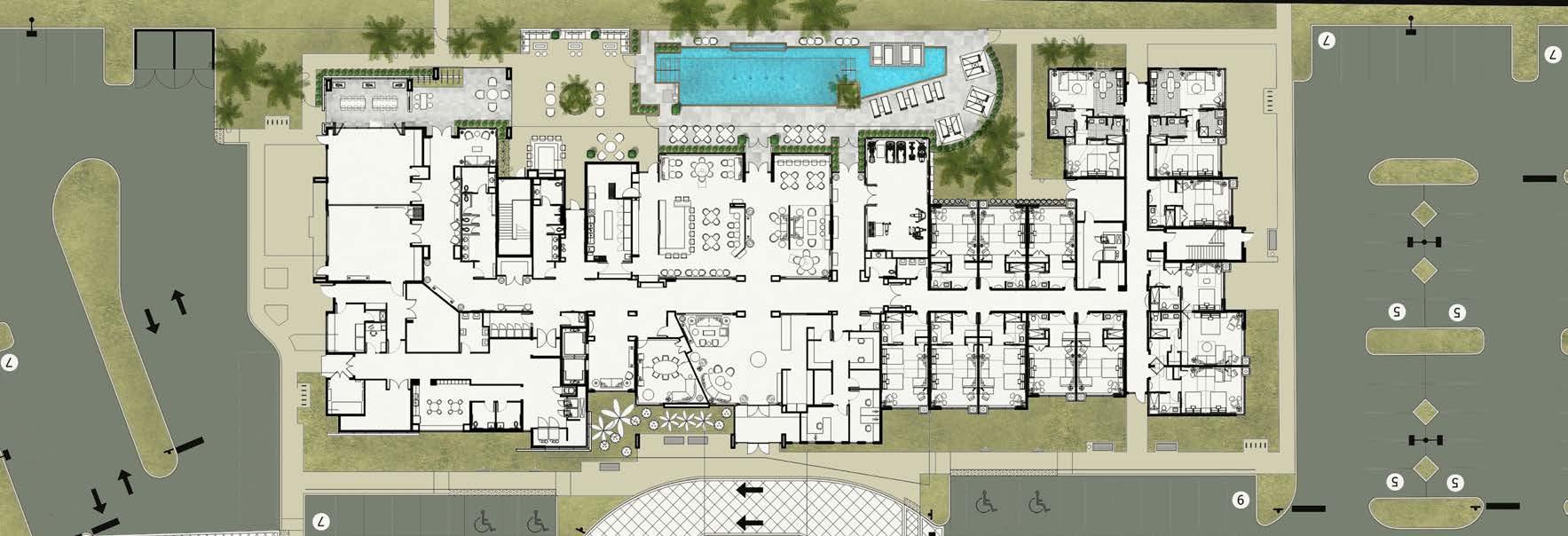
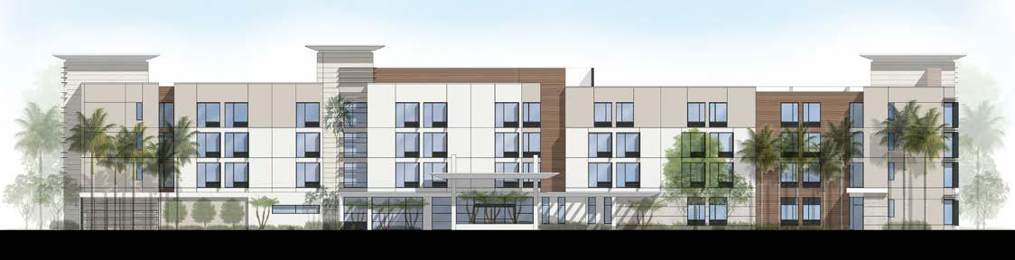
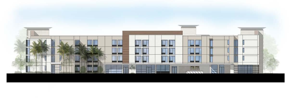
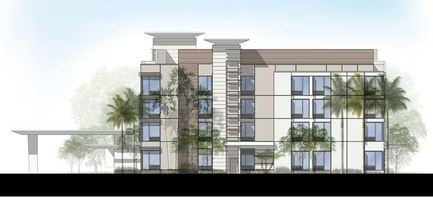
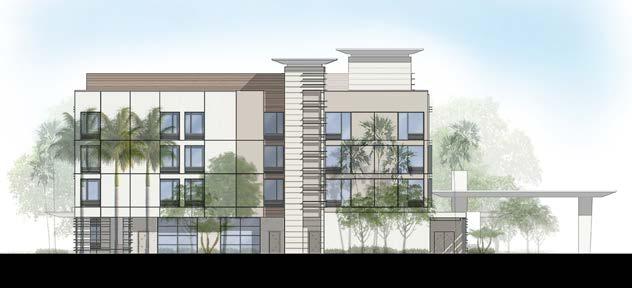
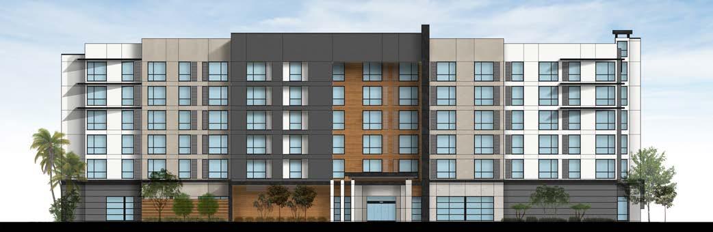
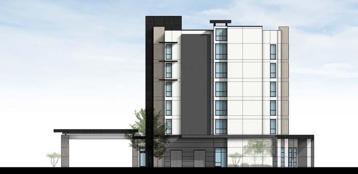
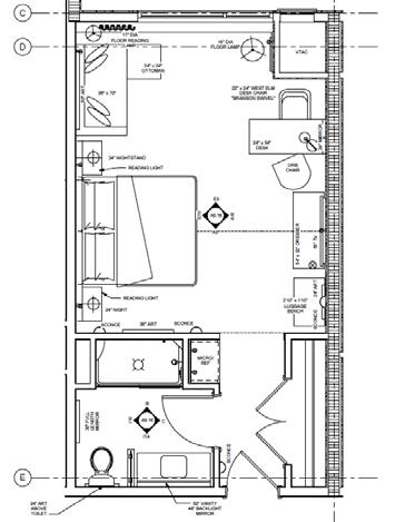
HOTEL DESIGN
L2 Studios Jupiter, FL
We were hired by a large development company to design multiple hotel projects they had acquired. I was made lead on these projects to keep communication streamlined between us and the client. This was one of the projects we began developing for them. We were charged with taking well known flagship brands and customizing them to an extent, to ensure a more upscale luxury experience was provided for the guests. The materials and finishes for the building use the surrounding Florida landscape as an inspiration and guideline.
SKILLS:
• Revit
• Enscape
• Adobe Photoshop
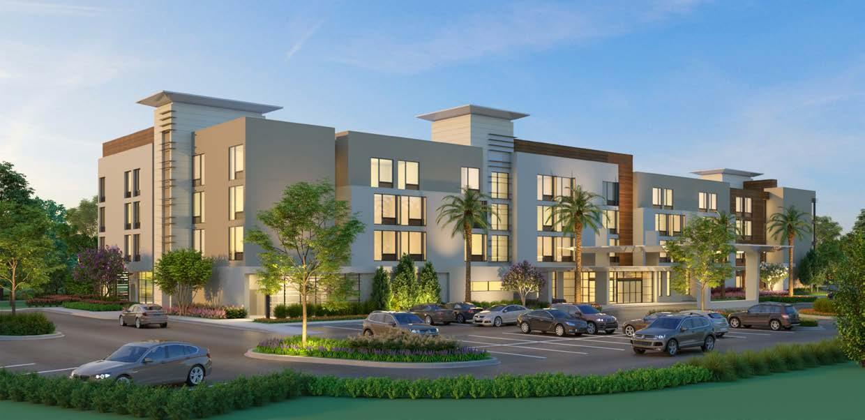
PAGE 6 EXTERIOR RENDERINGS:
RENDERED ELEVATIONS:
PAGE 7 RENDERED SITE PLAN:
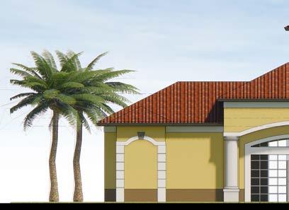
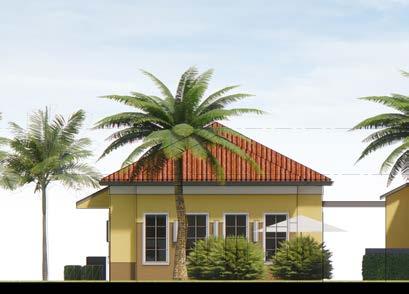
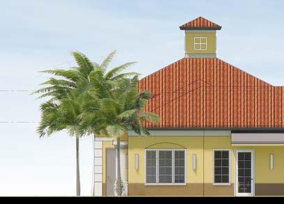
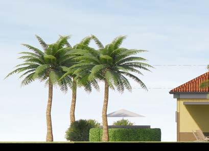
AMENITY CLUB HOUSE
L2 Studios Deland, FL
These clients hired my company to design the public areas for a new residential apartment complex they were developing, This included an amenity clubhouse for the residents use once opened. We designed the clubhouse to be cohesive with the brand’s established look of modern farmhouse with a luxurious interior. We also wanted to include as much site context as possible, with a nod to the nearby citrus tree farm and Florida landscape.
SKILLS:
• AutoCAD
• Sketchup
• Enscape
• Adobe Photoshop
EXTERIOR ELEVATIONS:
PAGE 8 M9 Leg Press Seated Raised circular banner 10'x10' dumbbell rack flat/incline Machine cable crossover flat/incline recumbant bikes recumbent bike Wall Functional Training Solution NORTH PROPOSED FLOOR PLAN:
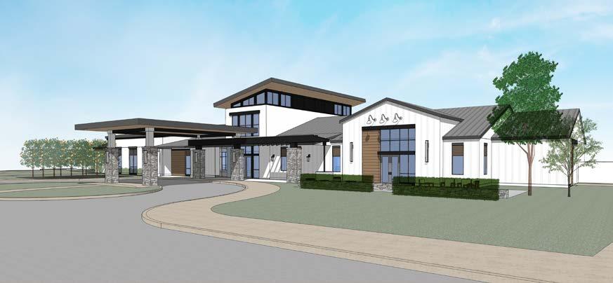
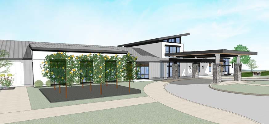
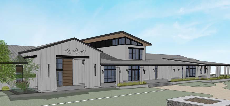
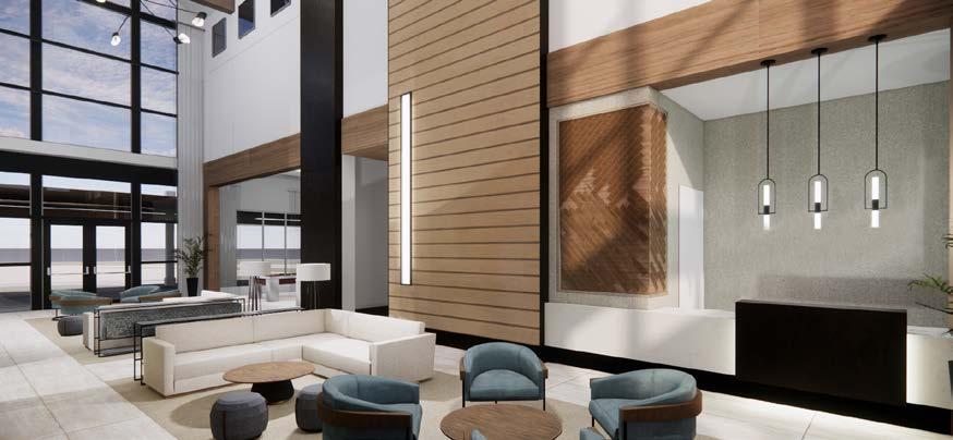
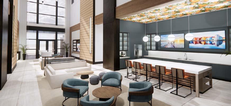
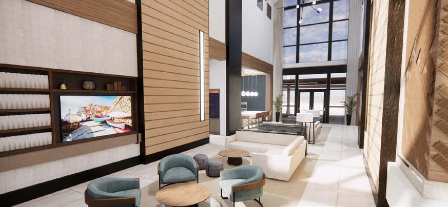
PAGE 9 EXTERIOR RENDERINGS: INTERIOR RENDERINGS:
CLUB HOUSE EXPANSION
L2 Studios Port St. Lucie, FL
This project was a smaller expansion job for an existing resort clubhouse. My company was tasked with designing a new building adjacent to the existing building on the site. This new building would provide more amenities to the resort guests, which included a new sales center, meeting room, outdoor grilling area + fire pit, and a fully equipped gym. The goal for this project was to ensure the new building was cohesive with the old building and would look as if it had been there from the start.
SKILLS:
• Revit
• Enscape
• Adobe Photoshop
GROUND FLOOR PLAN:
PAGE 10 TH1 A6.01 A6.01 Refrigerator Refrigerator F1 A4.02 A4.01 A1 Fitness Room 101 Multi-Purpose Room 102 Break Room 105 Sales Office 106 Housekeeping Closet 107 IDF 108 HVAC 104 Admin 112 Ops 113 Computer/Telephone 114 Men's Restroom 110 Women's Restroom 109 Lobby 111 Pantry 103 3/4" 8" 4' 8" 1/2" 4' 3/4" 5' 1/4" 5' 1/4" 5' 1/4" 8 1/2" 2' 11" 4' 1/4" 5' 1/4" 5' 1/4" 2' 1/4" 15' 1/4" 10 1/4" 5' 1/4" H1 102-A 103-A 101-A 101-B 101-C 101-D 101-E 101-F 101-G 101-H 101-I 102-C 102-B 102-D 102-E 102-F 105-A 104-A 105-B 106-D 106-B 106-C 106-A 108-A 107-A 109-A 110-A 111-B 111-A 112-A 113-C 113-A 113-B 114-A 5A1 2 4" - 6 ROOF PLAN: RENDERED EXTERIOR ELEVATIONS:
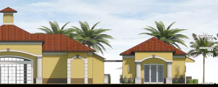
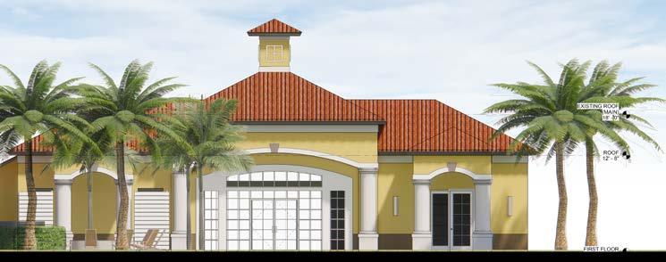
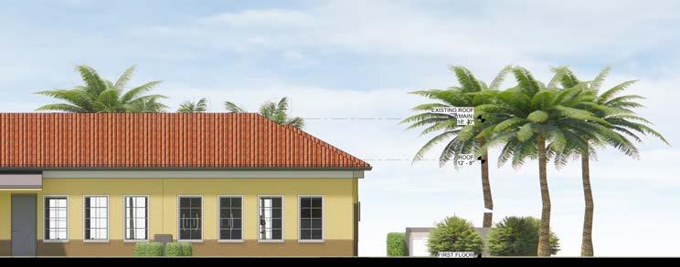
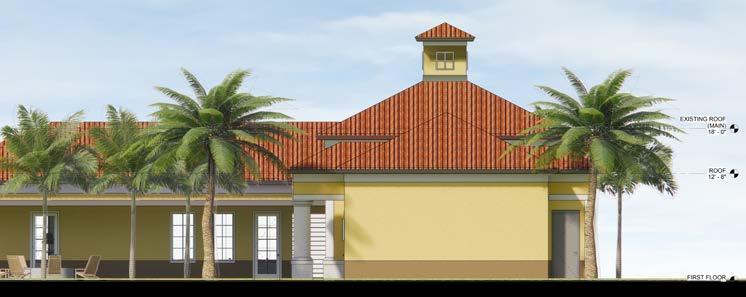
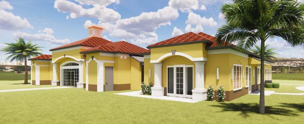
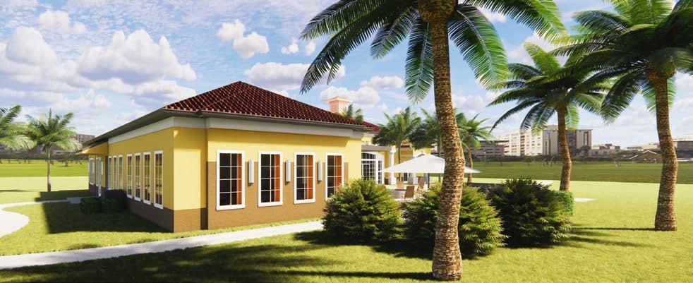
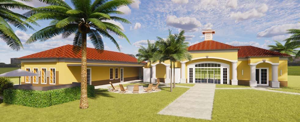
PAGE 11 ELEVATIONS: EXTERIOR RENDERINGS:
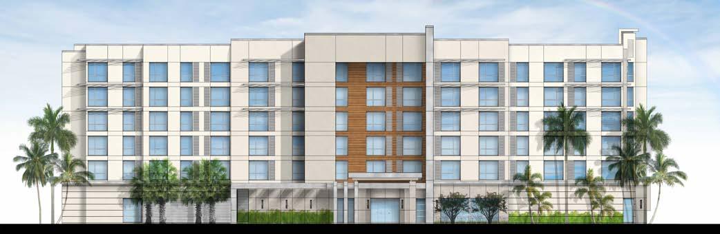
HOTEL DESIGN
L2 Studios | Tampa, FL
This was another hotel design for the large development company we were hired by to design multiple hotel projects. I was made lead on this project as well, to keep communication between us and the client streamlined.
Again, we were charged with taking a well known flagship brand and customizing them to an extent, to ensure a more upscale luxury experience was provided for each guests. The materials and finished for this building use the
surrounding Florida landscape as an inspiration and guideline. While also keeping in mind the brand standard designs provided to us by the flagship.

EXTERIOR ELEVATIONS FINISH OPTION #1:
EXTERIOR ELEVATIONS FINISH OPTION #2:
PAGE 12
SKILLS:
Revit
Adobe Photoshop
•
•
PAGE 13 UP 1 2 3 4 5 6 7 8 9 10 11 12 B C D CL G H E F A 23' 23' 15' 4" 15' 4" 15' 4" 8' 1" 8' 11" 30' 8" 30' 8" 23' 4" 23' 4" VESTIBULE MAIN LOBBY FRONT DESK LOUNGE BOARDROOM CORRIDOR MEETING ROOM #2 ELECTRICAL/ GENERATOR SWITCH MECHANICAL MEETING ROOM STORAGE WOMEN MEN SALES COMPUTER/ PBX 104 SF GENERAL MANAGER WORK ROOM TREATS LAUNDRY LINEN CHUTE ELEV LOBBY LINEN STORAGE HK OFFICE MECH DRYER EMPLOYEE BREAKROOM GUEST LAUNDRY VENDING MAINT. SECURITY CORRIDOR LUGGAGE CARTS WOMEN MEN POOL STORAGE FITNESS MECH POOL RR CORRIDOR FOOD PREP STORAGE BAR WATER HEATER A13 A6.03 A8 A6.03 HYDRATION STATION COFFEE NEWSPAPERS 24" 72" 39" REFRESH 3' 0" 6" 6" 3' 1/2" PANTRY MEETING ROOM #1 A13 A6.04 A8 A6.04 30" 48" CLEAR FLOOR SPACE 1' 72" 16" 42" MIRRORS (3) 42" MIRRORS (3) MIRRORS 48" 60" 48" 1/2" BUSINESS NOOK 24" 24" DOOR 6' 0" 12"x48" 24"x24" 2" 38" x 100" BREAKFAST 9' 3" FIRE PUMP 0" 2' 7" 1' 8" 3/4" 0" 3/4" 6' 0" COFFEE BAR 1/2" 1' 3/4" Drawn: Scale: S No: NOTICE: INCORPORATES FEDERAL PROPERTY DUPLICATED 1/4" Author GROUND FLOOR PLAN: TYPICAL GUESTROOM:
PLAZA DESIGN
McPherson Architecture Denver, CO
For this project my company was tasked with performing a plaza re-design located in a downtown business district office building. The clients wanted the space to feel more interacting and lively. The clients requested bright colors and an overall lightening up of the space. I worked on the concept design of the plaza and the initial presentation. I came up with two initial design options to present to the client, in order to decide how to further proceed.
OPTION #2 FLOOR PLAN:
SKILLS:
• SketchUp
• Podium
• Adobe Photoshop
PAGE 14
OPTION #1 FLOOR PLAN:
PAGE 15 OPTION #1 RENDERINGS: OPTION #2 RENDERINGS:
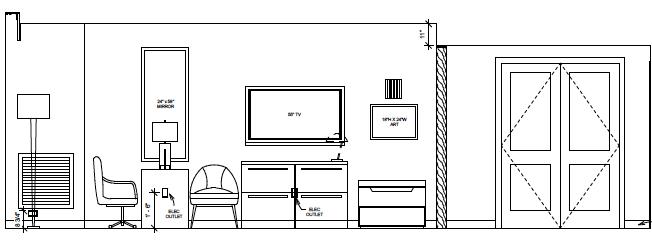
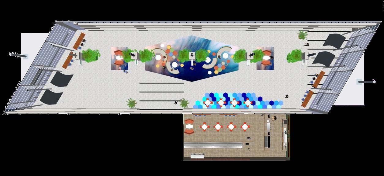
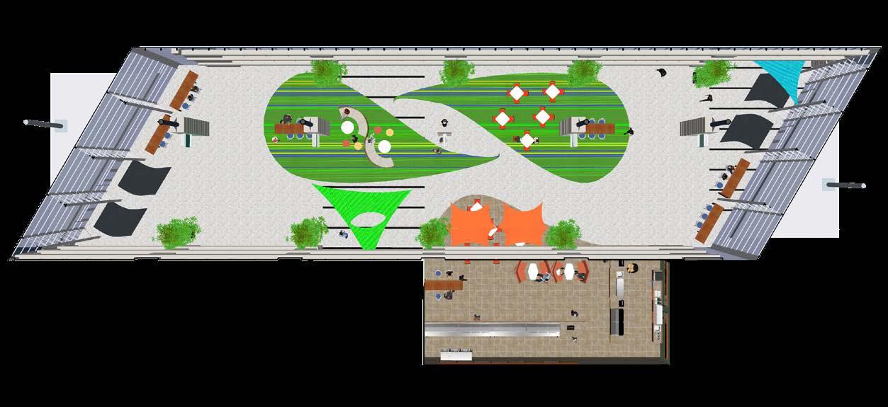
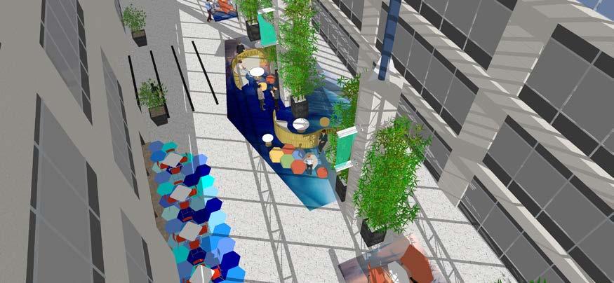
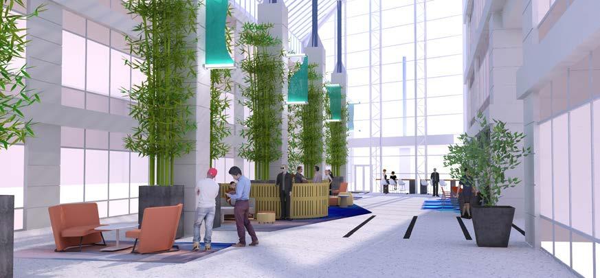
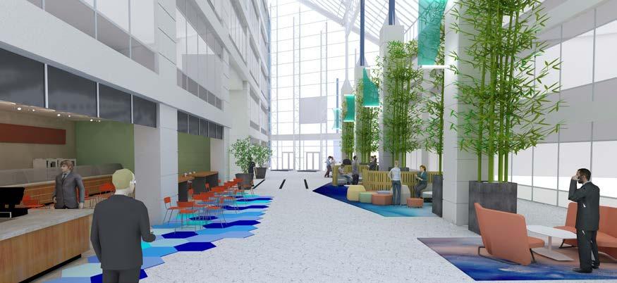
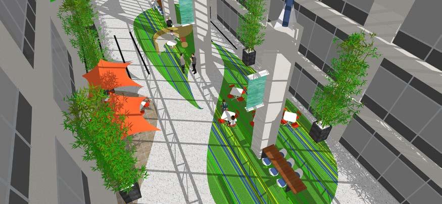
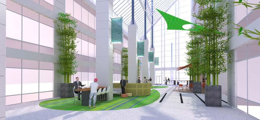
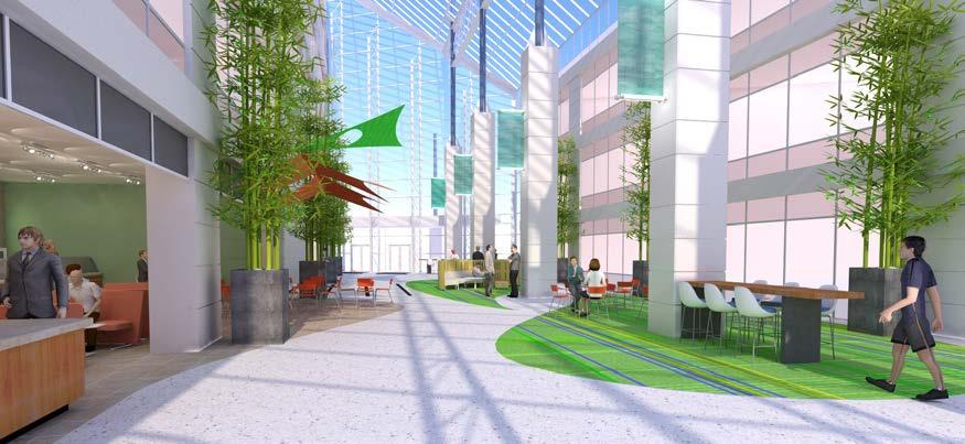
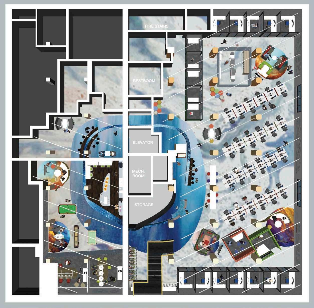
CO-WORK FACILITY
McPherson Architecture Denver, CO
For this project my company was tasked with designing a new co-work space in a historic downtown Denver building. The space was completely open, and we were given total freedom in the design. The only objectives being that the atmosphere was inviting and encouraged collaboration between individuals utilizing the space. I was in charge of creating the initial design and presentation to the client. In order to achieve the atmosphere they wished for, I conducted research of other co-working facilities around the area and took notes of all the pros/cons of each. Creatin a collaborative and openminded space was my driving force in my initial design.
SKILLS:
• SketchUp
• Podium
• Adobe Photoshop
PAGE 16
FLOOR PLAN:
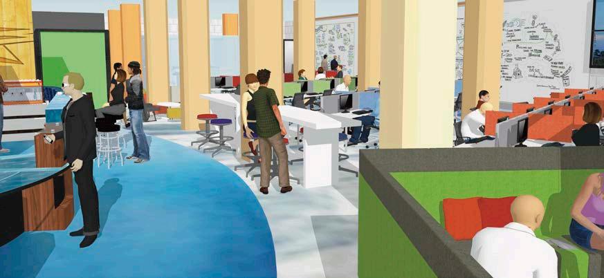
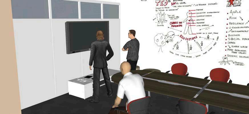
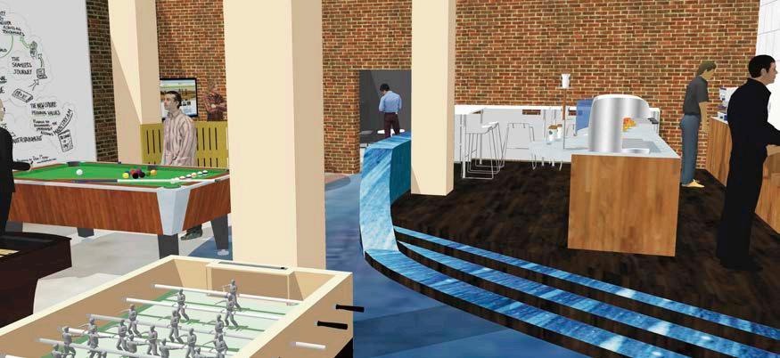
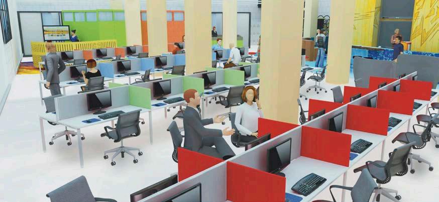
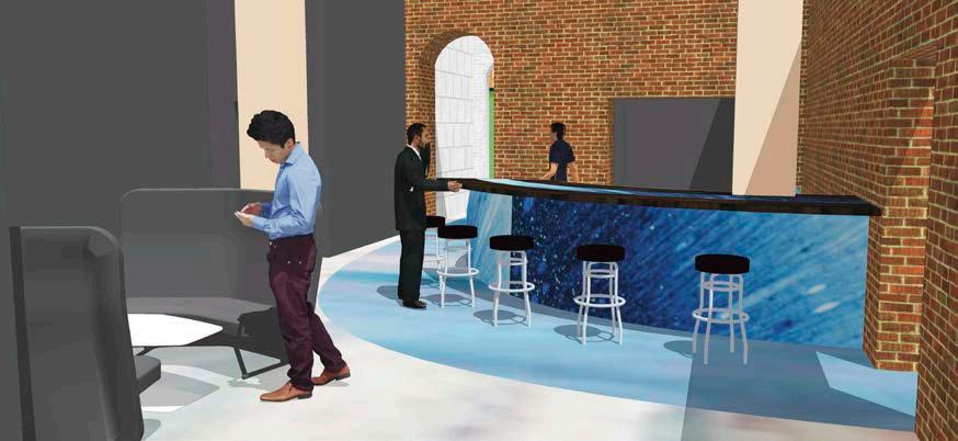
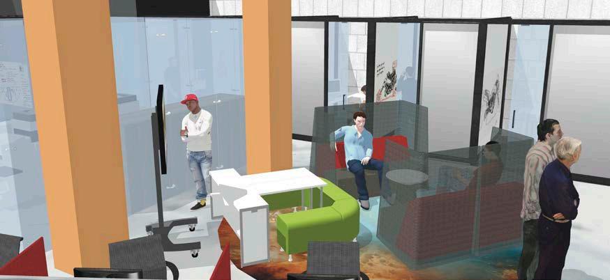
PAGE 17 RENDERINGS:
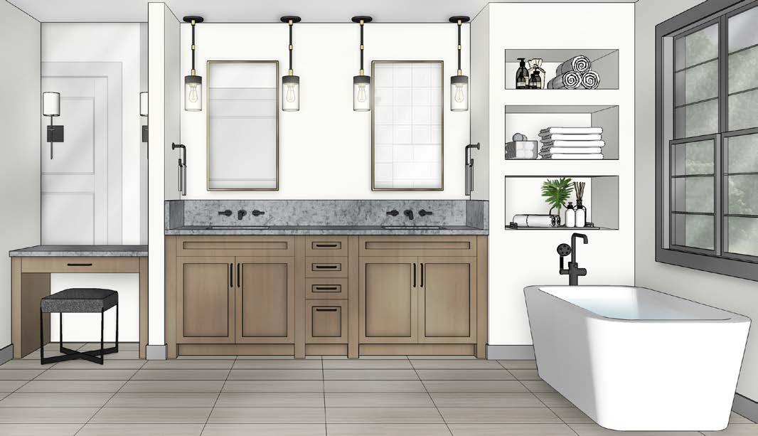
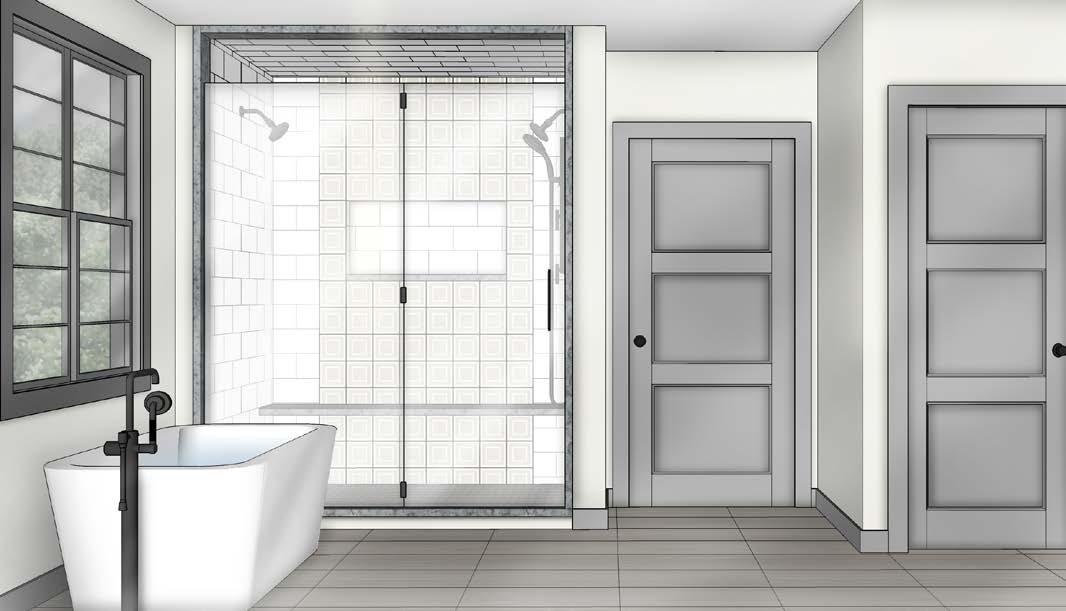
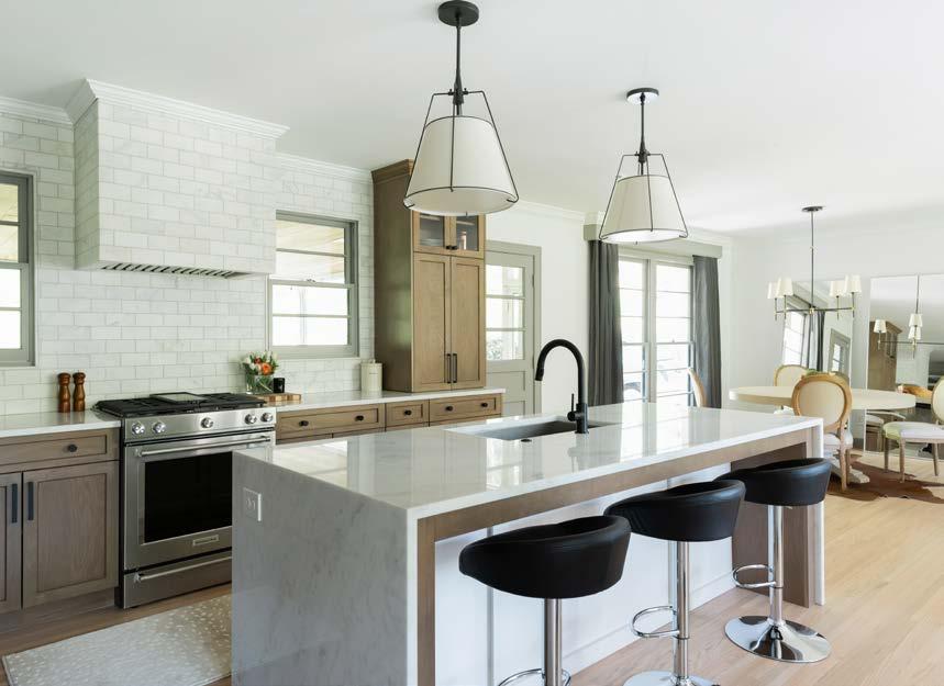
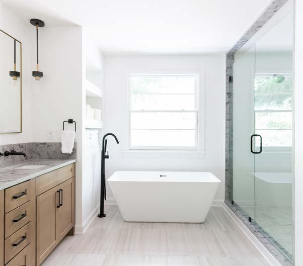
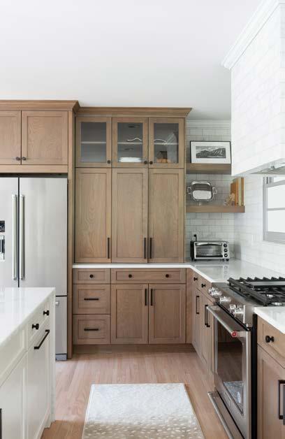
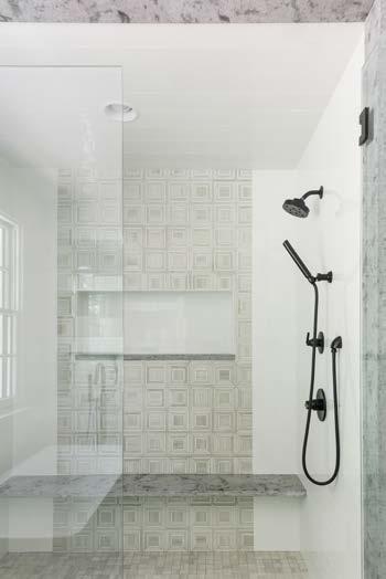
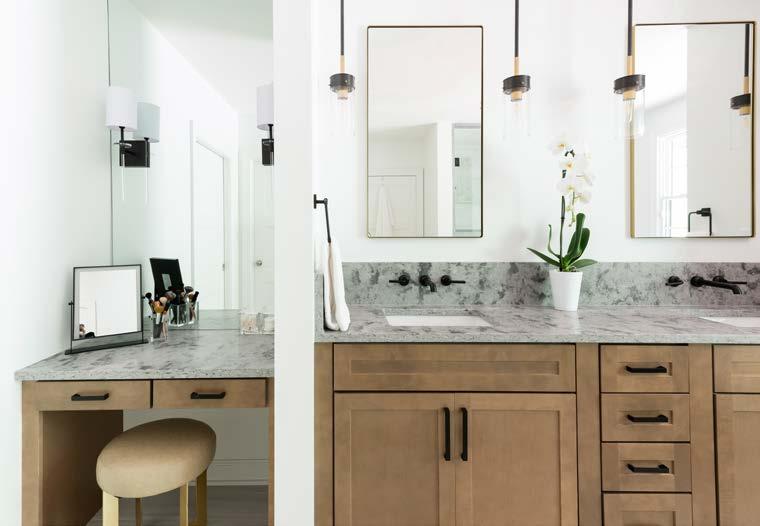
WHOLE HOUSE REMODEL
Merrill Construction Group Nashville, TN
This project was for a couple that was thinking of growing their family when they quickly realized their existing house was not quite ready for this. In order to best achieve a design that could grow with them, we decided to add an addition off the back of the house to accommodate a larger master suite for the couple. With a larger bedroom and spacious master bathroom. As well as, reconfigure their existing kitchen/living/dining room space and open it up to better suit their needs for entertaining guests. Natural light, efficient use of space, and modern finishes were the driving factors for this remodel. SKILLS:
• AutoCAD
• SketchUp
• Adobe Photoshop
PAGE 18 2868 2668 2668 1668 2068 1668 2868 2468 2468 2468 2868 2468 2468 2668 2068 2868 3068 3068 6465 9"AFF 2868 3735 3'9 AFF 3745 2'9 AFF 3030 4'1 AFF 2330 4'1 AFF 3745 2'9 AFF 2'9 AFF 3045 6445 2'9 AFF 6445 2'9 AFF 11'65 9"AFF 2868 2668 P.D KITCHEN 8'3" C.H. DINING 8'3" C.H. LIVING ROOM 8'3" C.H. FOYER 8'3" C.H. GUEST BEDROOM 8'3" C.H. OFFICE 8'3" C.H. MASTER BEDROOM 8'3" C.H. GUEST BATH 8'3" C.H. MASTER BATH 8'3" C.H. SHOWER CL CL CL CL CL CL CL CL SHOWER LINEN HALL UP DOWN 14'-11" 4'-2" 8'-5" 18'-5" 11'-11" 23'-3" 23'-5" 6'-10" 13'-5" 11'-3 4 12'-3" 2'-2" 13'-1" 13'-3" 2'-1" 13'-4" 3'-5" 3'-9" 3'-3" 19'-5" 28'-2 30'-8" 29'-4" 28'-3" 30'-7 EXISTING SCREEN PORCH REVISIONS Designed By: SCALE: 3/16"=1'-0" EXISTING FLOOR PLAN 01 2468 2668 3068 6465 9"AFF 2'9 AFF 3045 2'9 AFF 6445 2'9 AFF 11'65 9"AFF 2868 GUEST BATH 8'3" C.H. SHOWER LINEN UP DOWN 8'3" C.H. DINING (new)2468 COAT CLOSET FOYER 8'3" C.H. MASTER BEDROOM 8'3" C.H. 1' TRAY CEILING W/ INTERIOR CROWN MOULDING 2668 (new) 3068 (new) (new tempered) 6465 9"AFF 2468 CLOSET MASTER CLOSET 8'3" C.H. BENCH 4046 (new) BUILT IN OPEN SHELVES 3068 P.D. (new) 3068 C.O. BEDROOM 8'3" C.H. 8'3" C.H. W.C. 8'3" C.H. MASTER BATH 3068 6068 C.O. 4668 C.O. 2868 (new) 2635 3'9 AFF (new) 2635 3'9 AFF 2'-1 4'-8 27'-1" 13'-9 11'-10 9'-8" 13'-1" 12'-3" 6445 2'9 AFF 8'-9 2 14'-5 2 11'-10" 4 29'-2" 50'-3" 20' 33'-3 10'-9" 4 4 10'-2" 6'-5 2 24'-9" 3'-2" 19'-10 2 60'-4 3'-4 1 2 3'-7" KITCHEN 8'3" C.H. TRASH D.W. REF. 3'-3" 4' 2' 2' 1'-3" 8'3" C.H. LIVING ROOM EXISTING T.V. BUILT-IN 2668 2668 1668 1668 2868 2468 2468 CL CL CL CL CL 3068 (new) 2868 2868 CLOSET 4'-0 12'-6" OPEN SHELVES OFFICE 8'3" C.H. BEDROOM 8'3" C.H. 9'-2" 10'-6 2 7' 1'-10 3' 9'-11 14'-11" 2'-1" 13'-3" 2'-2" 4'-2" 4'-6" 8'-10" 5'-8 2 6'-3 2 3'-5" 3'-3" 12'-7" 14'-8" 7'-3" 2 3'-6" 6'-2 1'-6" 4' 2868 (salvaged) 7'-6" 1 8'-10 1'-6" 1'-6" 15' 9'-10" 8'-3" 10'-9 32 4'-3" 6'-9" 5'-3 3'-10" 6'-415 32 6'-0 recessed LVL to support load of previous exterior wall recessed LVL to support load of previous interior walls removed frame out tray with recessed (2) LVL's span on exterior and interior walls perpendicular with long side of tray Use long LVL's to support suspended beams @ short side to finish out framing recessed tray VANITY DESK EXISTING SCREEN PORCH TALL CAB. W/ HIDDEN MICRO TALL CAB- NEW 2X4 WALL6 x 11 CONCRETE PAD FOR NEW A/C 6' 11' 3'X3' CRAWL SPACE ACCESS DOOR **KITCHEN, LIVING, DINING, FOYER ALL ON EXISTING CRAWL** **UP STAIRS (GUEST BATH BEDROOMS) ALL ABOVE FINISHED SPACE** **ADDITION WILL BE ON CRAWL** DRAWERS W/ SHELVES ABOVE SHOES DOUBLE HANGING RODS DOUBLE HANGING RODS DOUBLE HANGING RODS LONG HANGING ROD DRAWERS W/ SHELVES ABOVE SHOES 3'-5" 2876 Sheet of 03 10 A101.1 SCALE: 3/16"=1'-0" PROPOSED FLOOR PLAN 03
EXISTING FLOOR PLAN:
KITCHEN RENDERINGS:
PROPOSED FLOOR PLAN:
MASTER BATH RENDERINGS:
PAGE 19
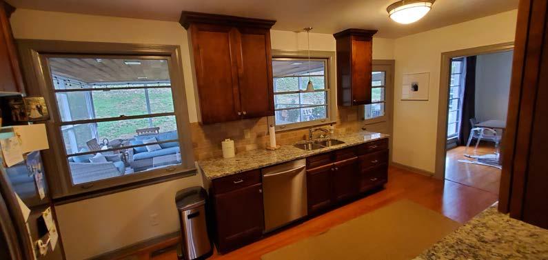
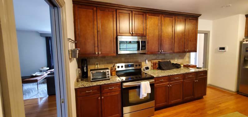
BEFORE CONSTRUCTION: AFTER CONSTRUCTION:
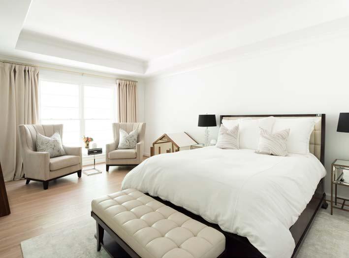

PAGE 20

All final photography + edits are credited to Ruby + Peach Photo (Nashville, TN)
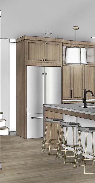
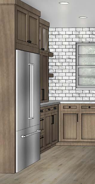
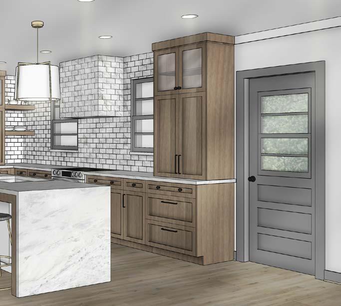
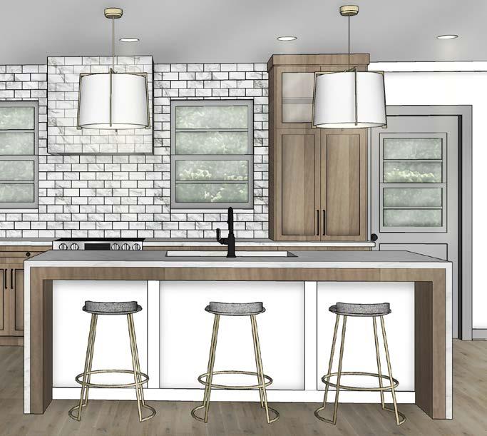
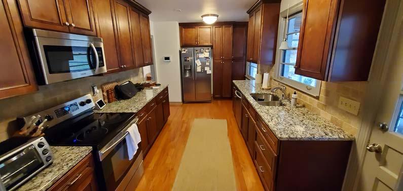
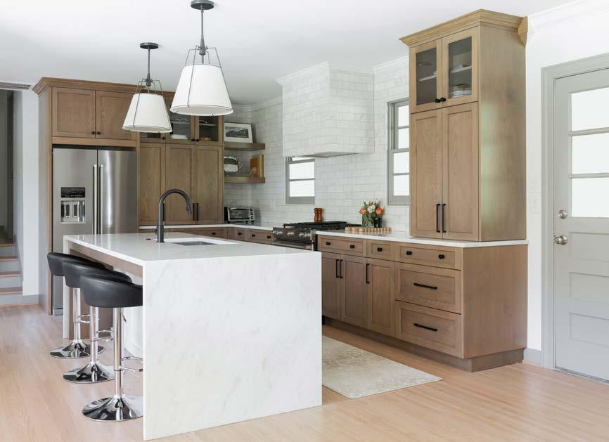
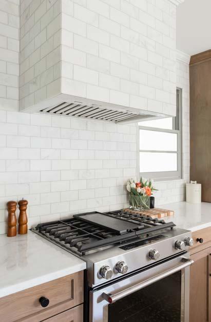
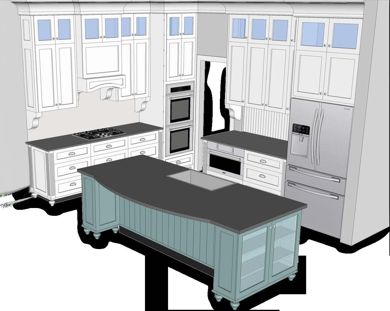
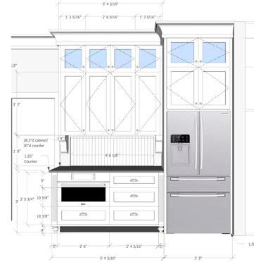
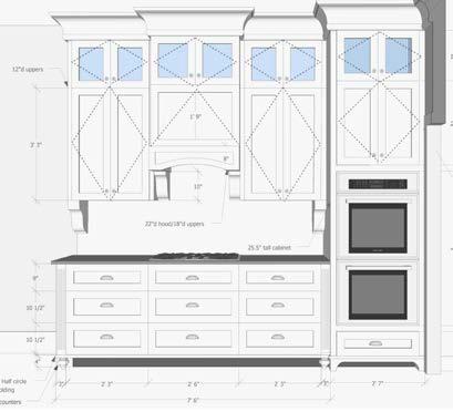
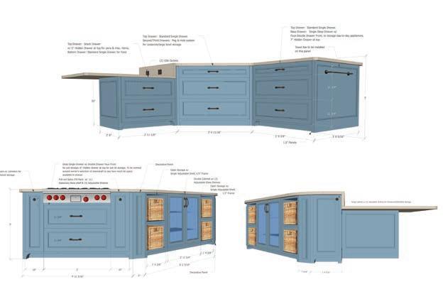
KITCHEN REMODEL
Merrill Construction Group | Nashville, TN
This client recently moved into her childhood home and wanted to start giving the space an upgrade, starting with the kitchen. The existing kitchen was closed off from the rest of the house, and did not allow for the large family to gather together. It was very
important for the kids to have a place to do their homework and eat snacks while the parents were in the kitchen or at the dining table. We started by removing the wall separating the kitchen from the rest of the house, and added in a large island to accommodate
the whole family as needed. We upgraded all appliances and finishes throughout the space. This client wanted to have fun with the finishes, so we provided multiple options to choose from that would keep the space unique and playful.
• AutoCAD
• SketchUp
• Adobe Photoshop
FLOOR PLAN: PROPOSED FLOOR PLAN: ELEVATIONS:
PAGE 22
SKILLS:
12'-8" 11'-1" 24'-2" 25'-11" 18'-1" 12'-2" 10'-5" 7'-8" 21135 21135 3260 3260 2868 P.D. 2868 P.D. 21068 LIVING 8' C.H. KITCHEN 8' C.H. DINING 8' C.H. 10' 3'-4" Description Approved REVISIONS Date Drawn: Designed By: Exhibit A in regards to the Construction Agreement Preliminary Drawings AM Final Definitions Phase AM Production Set AM HIGHLAND CREST_KRAFTElizabeth Bleecker 807 Highland Crest Dr. Nasvhille, TN 37205 AM 02/07/2020 Plot to full scale on 11x17 21135 3260 3260 21068 TRASH D.W. EXISITING REF. M.W. BELOW PANTRY W/ ROLLOUTS OPEN SHELVES OPEN SHELVES 2868 KITCHEN 8' C.H. DINING 8' C.H. LIVING 8' C.H. F.H. CAB EXISITING T.V. 24'-2" 10'-1 11 16 " 3'-4" 25'-11" 18'-1" 12'-2" 4'-10 11 16 8'-101 2 " 7'-6" 4'-3" 3' 2' 1' 1'-3" 4'-1 2 " 3'-9" 3'-9" 3'-81 2 " 1'-6" 2'-6" 4'-81 2 " 6'-1" 2'-6" 1'-3" 2' 2' 2'-6" 4'-10 11 16 " 2' 3' 1 2 " 1 2 " 3" 2'-6" 3" 1 1 2 " 1 1 2 " 13'-7 2 10'-9" 4" recess beam in ceiling to take place of structural wall being removed (2) doubled 2x12 LVL's Built-ins to be built by MCG w/ door fronts supplied by Markraft unfinished to be painted after install 2' 1 2 2'-6" 1 2 1'-3" 2' 3' 13'-7 2 3'-3" 1'-6" 3' 8' 2' 3" 2'-7 2 " 2'-6" 2'-6" 1' 1 2 2'-6" 1 2 13'-7 2 " 3" 2'-71 2 1'-9" 6' 3" 1 2 3' 1 2 " 2' 2'-6" 411 16 2' 10'-111 16 1' 211 16 1'-21 2 " 2'-5 2 " 2' 1 2 " 3' 1 2 " 10'-111 16 2' 1 2 2'-6" 1 2 1'-3" 2' 3' 13'-7 2 3'-3" 1'-6" 3' 8' 2' 3" 2'-7 2 " 2'-6" 2'-6" 1' 1 2 2'-6" 1 2 13'-7 2 " 3" 2'-71 2 3'-3" 3" 1'-9" 3" 1' 211 16 1'-21 2 " 2'-5 2 " 2' 1 2 " 3' 1 2 " 10'-111 16 " 3'-71 2 3'-71 2 7'-3" 2'-10 1 2 1 1 2 " 7'-6" 3' 2' 1 2 2'-6" 1 2 1'-3" 2' 3' 13'-7 2 3'-3" 1'-6" 3' 8' 2' 3" 2'-7 2 " 2'-6" 2'-6" 1' 1 2 " 2'-6" 1 2 13'-7 2 " 3" 2'-71 2 8' 3' 1'-6" 3'-3" 3" 1'-9" 6' 3" 1 2 1 2 " 2'-6" 411 16 " 2' 10'-111 16 " 1' 211 16 1'-21 2 2'-5 2 2' 1 2 3' 1 2 10'-111 16 3'-71 2 3'-71 2 7'-3" 2'-10 1 2 1 1 2 " 7'-6" 3' 3" 1'-9" 3' 2' 3" 7'-3" 2'-10 1 2 1 2 3' 7'-6" 2' 1 2 " 2'-6" 1 2 1'-3" 2' 3' 13'-71 2 3'-3" 1'-6" 3' 8' 2' 3" 2'-7 2 2'-6" 2'-6" 1' 11 2 2'-6" 2 13'-71 2 3" 2'-71 2 8' 3' 1'-6" 3'-3" 3" 1'-9" 6' 3" 1 2 3' 1 2 2' 2'-6" 411 16 2' 10'-111 16 1' 211 16 1'-21 2 " 2'-5 2 " 2' 1 2 3' 1 2 " 10'-111 16 "
EXISTING
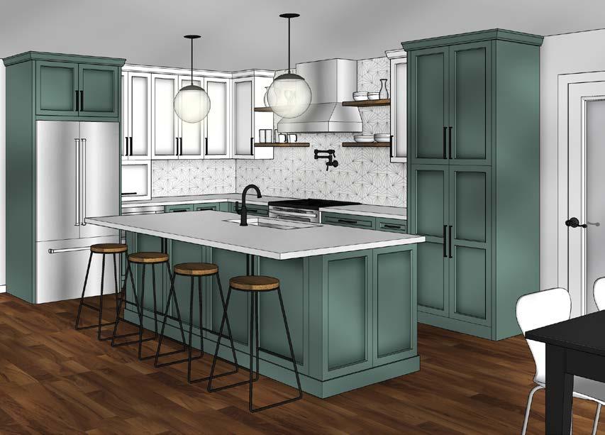
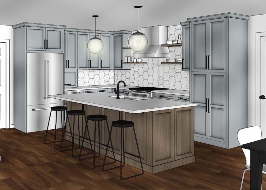
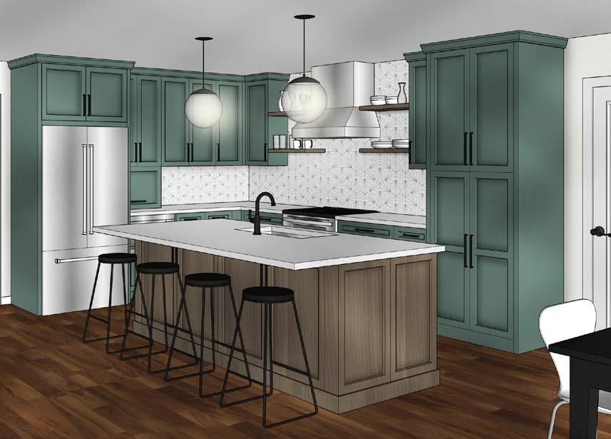
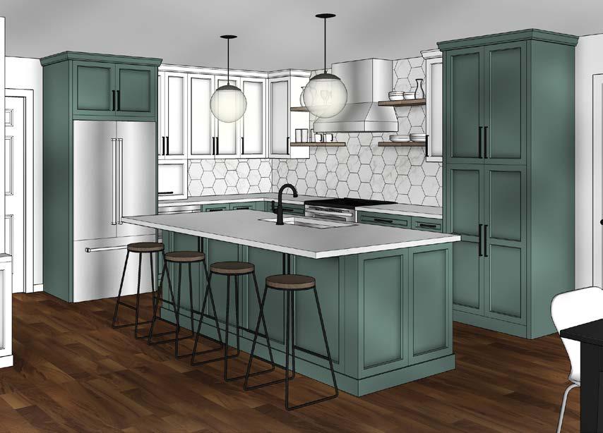
KITCHEN FINISH OPTIONS: 8' 3' 1'-6" 3'-3" 3" 3'-71 2 3'-71 2 7'-3" 2'-10 1 2 1 1 2 " 7'-6" 3' 3" 1'-9" 3' 2' 3" 7'-3" 2'-10 1 2 1 2 3' 7'-6" Sheet of Description Approved Date REVISIONS Date Drawn: Designed By: Exhibit A in regards to the Construction Agreement Preliminary Drawings AM 3/12 AM 4/2 Production Set HIGHLAND CREST_KRAFTElizabeth Bleecker 807 Highland Crest Dr. Nasvhille, TN 37205 1/2" = 1'-0" 05 06 E101.1 AM 02/07/2020 Plot to full scale on 11x17 Exhibit A in regards to the Construction Agreement HIGHLAND CREST_KRAFTElizabeth Bleecker 807 Highland Crest Dr. Nasvhille, TN 37205 02/07/2020 11x17 Description Approved Date REVISIONS Date Drawn: Designed By: Exhibit A in regards to the Construction Agreement Preliminary Drawings AM 3/12 AM 4/2 Production Set HIGHLAND CREST_KRAFTElizabeth Bleecker 807 Highland Crest Dr. Nasvhille, TN 37205 1/2" = 1'-0" AM 02/07/2020 Plot to full scale on 11x17 3'-71 2 " 3'-71 2 7'-3" 2'-10 1 2 1 1 2 7'-6" 3' 3" 1'-9" 3' 2' 3" 7'-3" 2'-10 2 1 1 2 3' 7'-6" Sheet of Description Approved Date REVISIONS Date Drawn: Designed By: Exhibit A in regards to the Construction Agreement Preliminary Drawings AM 3/12 Final Definitions Phase AM 4/2 Production Set HIGHLAND CREST_KRAFTElizabeth Bleecker 807 Highland Crest Dr. Nasvhille, TN 37205 1/2" = 1'-0" 05 06 E101.1 AM 02/07/2020 Plot to full scale on 11x17
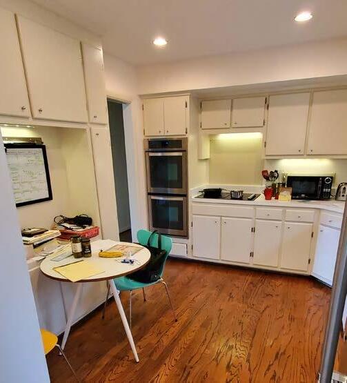
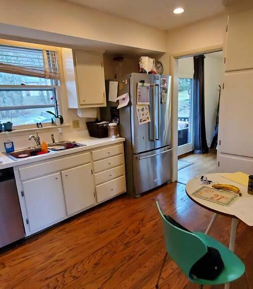
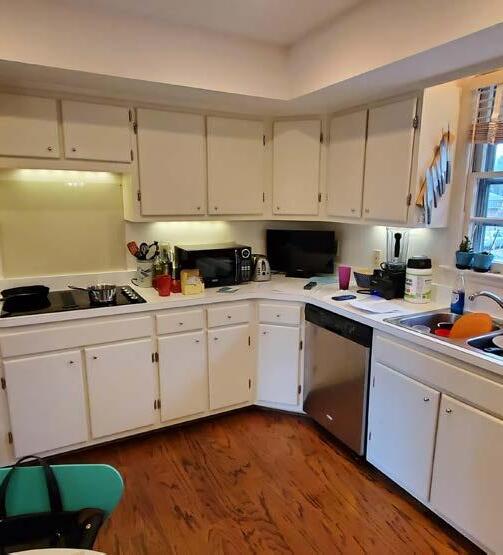
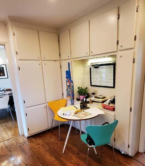

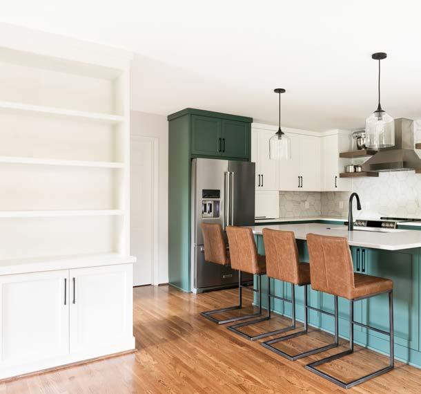

PAGE 24 BEFORE CONSTRUCTION: AFTER
CONSTRUCTION:

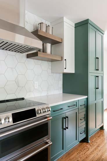
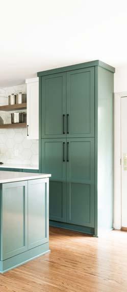
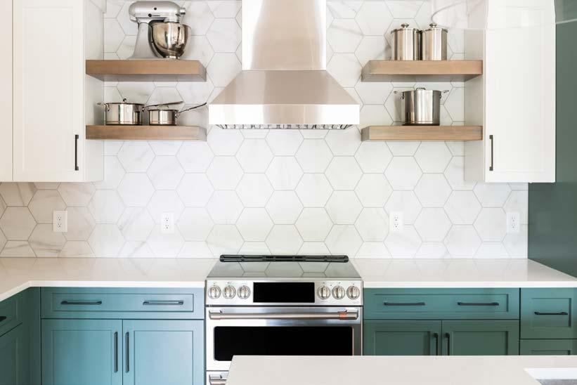
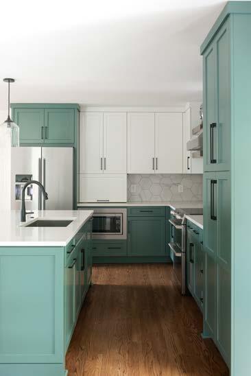
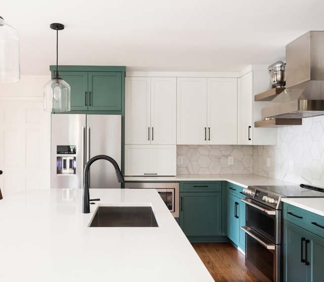
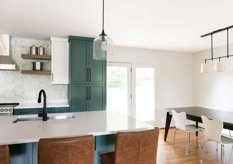
All final photography + edits are credited to Ruby + Peach Photo (Nashville, TN)
WHOLE HOUSE REMODEL
Merrill Construction Group Nashville, TN
These clients wanted to update their space to better suite their style as well as provide more adequate living space for their growing family. We started this process by adding a large addition to the side of the house. Creating a kitchen that was both aesthetically pleasing and functional was very important, as this couple loved to cook together. We also wanted to provide a better laundry space and larger master bathroom. Keeping things very open and natural feeling was key, so we made sure to include large windows wherever possible. This client had a unique midcentury modern style, and we definitely wanted to keep that in mind through the design.
SKILLS:
• AutoCAD
• Microsoft Excel


PAGE 26 3068 2868 2868 2868 2868 2668 2668 2868 C.O. 2668 C.O. 2068 2068 2068 2068 2668 P.D 3068 1668 2468 2268 2268 2068 2068 68110 4'11"AFF 7746 bay 11030 2250 2250 10358 1'3"AFF 102110 5'1"AFF 69110 5'1"AFF 3044 2'6"AFF 3044 2'6"AFF 4010 12" BFC 3030 12" BFC LIVING 7'10" C.H. CARPORT STORAGE MASTER BATH 7'10" C.H. LAUNDRY 7'11" C.H. MASTER BED 7'11" C.H. HIS CLOSET HER CLOSET COVERED PORCH sloped ceiling KITCHEN 8'0" C.H. DINING 8'0" C.H. BATH 7'10" C.H. KIDS ROOM 8'1" C.H. OFFICE 7'11" C.H. CL CL CL CL CL 23' 11'-7" 24'-5" 2'-1" 13'-2" 10'-3 2'-6" 1'-2 4'-10" 17'-5" 6'-11" 7'-3" 14'-7" 6'-11" 5'-7" 5'-5" 7'-2" 20'-1" 5'-6 2 16'-2" 6'-3" 19' 2'-6" 4'-9" 2'-4" 3'-6" 9'-8" 5'-6" 3'-1" 4'-6 1 8' 3'-8" 5' 3'-6" 6068 SLIDER Sheet of Description Approved Date REVISIONS Date Drawn: Designed By: Exhibit A in regards to the Construction Agreement Concept Dev. V.2 AM 11/13 Design Review #1 V.3 AM 12/23 OSEMV.4 AM 1/13 Design Review #2 V.5 AM 2/2 Final Construction Set V.6 AM 2/10 MAYWOOD_FANSHERBrad + Maggie Fansher 5001 Maywood Drive Nashville, TN 37211 3/16" = 1'-0" 02 14 A100.1 AM 08/06/2020 Plot to full scale on 11x17 SCALE: 3/16" = 1'-0" EXISTING FLOOR PLAN 01 BATH 7'10" C.H. KIDS ROOM 8'1" C.H. OFFICE 7'11" C.H. DECK TO DEMO STAIRS DEMO BUILT IN DESK @ CLOSET DEMO CEILING FIXTURE TO BE REPLACED WITH FAN (W/LIGHT) DEMO CEILING FIXTURE TO BE REPLACED WITH FAN (W/LIGHT) DEMO PLAN 02 3068 2868 2868 2068 2068 2068 2068 2668 P.D 1668 2468 2268 2268 2068 2068 REPLACE NEW SIZE 6858 1'3"AFF REPLACE SAME SIZE 10358 1'3"AFF REPLACE SAME SIZE 102110 5'1"AFF 69110 REPLACE SAME SIZE 2'6"AFF REPLACE SAME SIZE 3044 2'6"AFF DO NOT REPLACE 4010 12" BFC MASTER BATH 8'0" C.H. MASTER BED 7'11" C.H. HIS CLOSET HER CLOSET OPEN DECK BATH 7'10" C.H. KIDS ROOM 8'1" C.H. OFFICE 7'11" C.H. CL CL CL CL CL REF. WASH DRY EXISTING ISLAND 3068 NEW NEW 2668 P.D.(2) NEW2868 CLOSET 3068NEW 8'0" C.H. OFFICE C.H. TBD STORAGE 3068 P.D. 8'0" C.H. MUDROOM 8'0" C.H. NEW3068 BENCH PEG BOARD 8'0" C.H. STOOP NEW2668(2) PLAYROOM 8'0" C.H. HALL HALL 8'0" C.H. 2' 17'-7" 18'-7 2 13' 6'-4 4' 11' 9'-8" 12'-7" 4'-2" 2'-8" 4'-0 6'-11" 14'-7" 7'-3" 15'-0 2 13'-4 2 D.W. TALL CABINETS BEV. COOLER WINE RACK TRASH PANTRY. 3068 BARN NEW 5'-37 4'-6" 11'-9" 7'-8 11'-0 RAISE SILL TO BE @ 3' AFF OPEN SHELF COUNTERTOP CABINET OPEN SHELF 24'-5" 11'-7" 22'-7 4' 9'-8 2 8'0" C.H. DINING 10'-10 2 4'-6" 4' 2 - EXISTING WALLS - NEW 2x4 WALLS - NEW 2x6 WALLS WALL LEGEND 4'-6" NEW 6058 1'3" AFF NEW 3033 3'8" AFF NEW 12/0 6/8 DOUBLE SLIDER 8'0" C.H. LIVING 3'-6" 8' 9' 7'-7" 10'-1" 14'-1" 2650 NEW 3033 3'8" AFF NEW 3033 3'8" AFF 3033 3'8" AFF NEW 6058 1'3"AFF 2X4 SKYLIGHT 2X4 SKYLIGHT 2X2 SKYLIGHT NEW 1'11"AFF 3' X 3' CRAWL SPACE ACCESS DOOR MIN. 16 X 16 CHASE TO VENT RETURN FROM ATTIC 1'-4" 2' 1' 7015 2650 3'-5 9'-3" 4'-6" ROBE HOOKS 6'-4" 7'-2 1'-3 1'-3 1'-3 1'-11 4'-3" 6'-7 2 2'-10" 9" 4'-8" 3'-7 2 2'-7 5'-5 12'-107 16 32 3' 2 3' 4 3' 4'-6 4 6' 1'-1017 32 32 17'-5 3'-11" 6' 6' NEW RAIL, GATE, STAIRS GATE 2'-2 2' 2' 2'-11 Sheet of Description Approved Date REVISIONS Date Drawn: Designed By: Exhibit A in regards to the Construction Agreement Concept Dev. V.2 AM 11/13 Design Review #1V.3 AM 12/23 OSEM V.4 AM 1/13 Design Review #2V.5 AM 2/2 Final Construction Set V.6 AM 2/10 MAYWOOD_FANSHERBrad + Maggie Fansher 5001 Maywood Drive Nashville, TN 37211 1/8" = 1'-0" 04 14 A101.1 MB 08/06/2020 Plot to full scale on 11x17 SCALE: 3/16"=1'-0" PROPOSED FLOOR PLAN 03 LEGEND LIGHT SWITCH WALL OUTLET 6" CEILING CAN LIGHT CHANDELIER DROP PENDANT UNDER CABINET LIGHTING CAN + FAN LIGHT COMBO D CEILING FAN FLORESCENT STRIP CLOSET LED CABINET PUCK LIGHT CEILING FLUSH MOUNT FLOOD LIGHT **PER METRO CODES: UPDATE ALL SMOKE DETECTORS THROUGHOUT HOUSE** **PER METRO CODES: UPDATE HOUSE TO INCLUDE CO2 SENSORS @ EVERY FLOOR** **ALL FIXTURE LOCATIONS IN ELECTRICAL PLAN ARE APPROXIMATE. FOR FINAL DECORATIVE LIGHTING LOCATIONS SEE DRAWINGS/SCOPE OF WORK. RECESSED LIGHTING WILL BE DETERMINED BY CEILING FRAMING TO BE PLACED ON SITE** **OUTLETS + SWITCHES LOCATIONS WILL BE BASED ON ELECTRICAL PLAN SUBJECT TO CONDITIONS ON SITE H.O. TO VERIFY LOCATIONS AFTER FRAMING/ROUGH IN PRIOR TO DRYWALL** EXISTING HVAC UNIT ELECTRICAL PLAN 04
EXISTING FLOOR PLAN: DEMOLITION PLAN: PROPOSED FLOOR PLAN: ELECTRICAL PLAN:


PAGE 27 DEMO FLOOR DEMO FLOOR DEMO FLOOR DEMO FLOOR DEMO CONCRETE TO ALLOW FOR NEW FOOTERS @ ADDITION DEMO ROOF COVERING EXISTING PORCH REMOVE PATCH DO NOT DEMO BRICK LIVING 7'10" C.H. CARPORT STORAGE MASTER BATH 7'10" C.H. LAUNDRY 7'11" C.H. MASTER BED 7'11" C.H. KITCHEN 8'0" C.H. DINING 8'0" C.H. notify client when window is removed to check actual opening width notify client when floor is removed to check quality of concrete floor to determine if wants to keep exposed REMAIN STAIRS + RAILING ONLY DEMO PENDANTS TO REPLACE WITH CEILING CANS Sheet of Description Approved Date REVISIONS Date Drawn: Designed By: Exhibit A in regards to the Construction Agreement Concept Dev. V.2 AM 11/13 Design Review #1 V.3 AM 12/23 OSEMV.4 AM 1/13 Design Review #2 V.5 AM 2/2 Final Construction Set V.6 AM 2/10 MAYWOOD_FANSHERBrad + Maggie Fansher 5001 Maywood Drive Nashville, TN 37211 1/8" = 1'-0" 02 14 D100.1 AM 08/06/2020 Plot to full scale on 11x17 SCALE: 3/16" = 1'-0" 3' 11 2 " 3' 1' 1' 2'-3" 18'-71 2 " 11 2 " 1 1 2 7'-6 1 2 " 4" 3' 3' 11 2 " 3' 3'-6" 1'-6" HOOD MW LIVE EDGE SHELF 3' 17 16 " 2'-1" 1'-6" 3' 2' 1'-9" 10'-513 16 " 12'-107 16 " H.O. DW TRASH SHELF 13 4 " 2' 1'-41 2 " 2'-8" 1'-41 2 " 2' 13 4 " 9'-81 2 " 4" 3' 1'-8 1 2 " 5' 1 1 2 " 8' 1" 2' 3 4 " 3 4 " 2' 1" 5'-5" H.O. PROVIDE + FIXTURE 4 1 2 " 3'-0 1 2 " 2" 3" 2'-4" 3" 2'-4" 3" 2'-4" 3" 8' 2'-6" 2'-5 1 2 " 2'-1" 4'-1" 2'-1" Description Approved REVISIONS Date Drawn: Designed By: Exhibit A in regards to the Construction Agreement Concept Dev.V.2 AM Design Review #1V.3 AM OSEMV.4 AM Design Review #2V.5 AM Final Construction SetV.6 AM MAYWOOD_FANSHERBrad + Maggie Fansher 5001 Maywood Drive Nashville, TN 37211 MB 08/06/2020 Plot to full scale on 11x17 SCALE: 3/8"=1'-0" Coffee Bar Elevation 07 2'-7 11 16 " 4 1 2 4'-53 4 " 3'-23 4 " 3'-8" 4" 4' 7'-81 2 " 11'-9" 11'-5" 4' 10 1 2 " 6" 3'-113 4 " 2'-10 1 2 " CL 2'-2" 4'-3 11 16 " 4'-6" 6' 2' 8' 1' 8' 4' 7'-2" 2' 1'-8" 6' 4'-6" SKYLIGHT 2'-5" 1'-1" SCALE: 3/8"=1'-0" Master Bath | Vanity 14 SCALE: 3/8"=1'-0" Master Bath | Back Shower Wall 15 Ledge Detail 16 D D D D D 3WAY 3WAY 3WAY 3WAY D 3WAY D 3WAY D 3WAY CAB INSIDE CAB INSIDE INSIDE CTOP CTOP CTOP CTOP CTOP CTOP CTOP GFI DUPLEX WASH DRY D.W. BEV. COOLER AIR SWITCH EXISTING PANEL EQ EQ 2X4 SKYLIGHT 2X4 SKYLIGHT 2X2 SKYLIGHT NEW THERMO PROPOSED NEW HVAC UNIT LOCATION NEW PANEL NO LIGHT replace pendants with recessed cans INSIDE Sheet of Description Approved Date REVISIONS Designed By: Exhibit A in regards to the Construction Agreement Concept Dev. V.2 AM 11/13 Design Review #1 V.3 AM 12/23 OSEM V.4 AM 1/13 Design Review #2 V.5 AM 2/2 Final Construction Set V.6 AM 2/10 MAYWOOD_FANSHERBrad + Maggie Fansher 5001 Maywood Drive Nashville, TN 37211 3/16" = 1'-0" 05 14 A101.2 MB 08/06/2020 Plot to full scale on 11x17 SCALE: 3/16"=1'-0" KITCHEN ELEVATIONS: BATHROOM DETAILS: 11 2 " 3' 3' 11 2 " 3' 1' 2'-10" 31 2 " 2' 1' 2'-3" 18'-71 2 " 3' 1'-8 1 2 " 8' 11 2 " 1 1 2 " 7'-6 1 2 " 4" 3' 3' 11 2 " 3' 3'-6" 1'-6" 4'-41 2 " H.O. PROVIDE SHELF HOOD MW LIVE EDGE SHELF 5' 3' 8' 17 16 " 2'-1" 1'-6" 3' 2' 1'-9" 2'-5" 4" 1 1 2 " 3' 5 8 " 2'-3" 5 8 " 1'-8 1 2 " 10'-513 16 " 12'-107 16 " H.O. PROVIDE SHELF DW TRASH SHELF 13 4 " 2' 1'-41 2 " 2'-8" 1'-41 2 " 2' 13 4 " 9'-81 2 " 1" 2' 3 4 " 3 4 " 2' 5'-5" H.O. PROVIDE + FIXTURE 4 1 2 3'-0 1 2 " 2" 3" 2'-4" 3" 2'-4" 3" 2'-4" 3" 8' 2'-6" 2'-5 1 2 2'-1" 4'-1" 2'-1" SCALE: 3/8"=1'-0" Kitchen Elevation | Stove 06 SCALE: 3/8"=1'-0" Kitchen Elevation | Sink 08 Coffee Bar Elevation 07 Kitchen Elevation | Island 09 LIVE EDGE SHELF 5' 3' 8' 17 16 " 2'-1" 1'-6" 3' 2' 1'-9" 2'-5" 4" 1 1 2 3' 5 8 " 2'-3" 5 8 " 1'-8 1 2 " 10'-513 16 " 12'-107 16 " H.O. PROVIDE SHELF DW TRASH 4 1 2 " 3'-0 1 2 " 2" 3" 2'-4" 3" 2'-4" 3" 2'-4" 3" 8' 2'-6" 2'-5 1 2 " 2'-1" 4'-1" 2'-1" SCALE: 3/8"=1'-0" Kitchen Elevation | Stove 06 SCALE: 3/8"=1'-0" Kitchen Elevation | Sink 08 SCALE: Coffee Bar Elevation 07 SCALE: Kitchen Elevation | Island 09 11 2 3' 3' 11 2 " 3' 1' 2'-10" 31 2 " 2' 1' 2'-3" 18'-71 2 " 3' 1'-8 1 2 " 8' HOOD MW LIVE EDGE SHELF 5' 3' 8' 17 16 " 2'-1" 1'-6" 3' 2' 1'-9" 2'-5" 4" 1 1 2 " 3' 5 8 " 2'-3" 5 8 " 1'-8 1 2 " 10'-513 16 " 12'-107 16 " H.O. PROVIDE SHELF DW TRASH SCALE: Kitchen Elevation | Stove 06 SCALE: 3/8"=1'-0" Kitchen Elevation | Sink 08 2'-7 11 16 " 4 1 2 " 4'-53 4 " 3'-23 4 " 3'-8" 4" 4' 7'-81 2 " 11'-9" 11'-5" 4' 10 1 2 " 6" 3'-113 4 " 2'-10 1 2 " CL 2'-2" 4'-3 11 16 " 4'-6" 6' 2' 8' 1' 8' 4' 7'-2" 2' 1'-8" 6' 4'-6" SKYLIGHT 2'-5" 1'-1" 2x6 floor tile to continue up back wall of shower + ledge vertically stacked bullnose tile @ ledge (finish side to be 2" side) 4x20 tile @ side walls of shower Recessed linear drain to be installed @ long wall of shower
PAGE 28 FINISHED FLOOR TOP OF WINDOWS TO MATCH EXISTING TO MATCH EXISTING TO MATCH EXISTING **EXISTING SLOPE OF HIP ROOF ASSUMED TO BE 4.5:12 SLOPE TO MATCH @ NEW ADDITION HIP ROOF. VERIFY ON SITE PRIOR TO ROOF FRAMING FOR ADDITION** 4.5 12 4.5 4.5 23' 12'-6" 40'-9 8' 8'-3" 23' 3'-1 8 16'-6" 29'-1 14'-1" 3 E A A A C D 6'-11" FINISHED FLOOR FINISHED CEILING TOP OF WINDOWS TO MATCH EXISTING TO MATCH EXISTING 4.5 4.5 12 FLAT 3 14'-1" 29'-1 2 4'-5" 19'-4" 23' 8'-3" 8 23' 15'-4" 37'-11 2 2 CRAWL ACCESS H C 4 Sheet of Description Approved Date REVISIONS Date Drawn: Designed By: Exhibit A in regards to the Construction Agreement Concept Dev.V.2 AM 11/13 Design Review #1 V.3 AM 12/23 OSEM V.4 AM 1/13 Design Review #2 V.5 AM 2/2 Final Construction Set V.6 AM 2/10 MAYWOOD_FANSHERBrad + Maggie Fansher 5001 Maywood Drive Nashville, TN 37211 1/8" = 1'-0" 12 14 E101.5 MB 08/06/2020 Plot to full scale on 11x17 SCALE: 1/8"=1'-0" ELEVATION SCALE: 1/8"=1'-0" ELEVATION FINISHED FLOOR FINISHED CEILING TOP OF WINDOWS TO MATCH EXISTING TO MATCH EXISTING **EXISTING SLOPE OF HIP ROOF ASSUMED TO BE 4.5:12 SLOPE TO MATCH @ NEW ADDITION HIP ROOF. VERIFY ON SITE PRIOR TO ROOF FRAMING FOR ADDITION** 4.5 12 4.5 12 4.5 FLAT 23' 12'-6" 40'-9 8' 8'-3" 23' 3'-1 8 16'-6" 3 E A A A C D 6'-11" FINISHED CEILING TOP OF WINDOWS TO MATCH EXISTING TO MATCH EXISTING TO MATCH EXISTING EXISTING 4.5 12 12 FLAT 3 14'-1" 29'-1 2 4'-5" 19'-4" 23' 8'-3" 8 23' 15'-4" 37'-11 2 2 CRAWL ACCESS H C 4 Sheet of Description Approved Date REVISIONS Date Drawn: Designed By: Exhibit A in regards to the Construction Agreement Concept Dev.V.2 AM 11/13 Design Review #1V.3 AM 12/23 OSEMV.4 AM 1/13 Design Review #2V.5 AM 2/2 Final Construction SetV.6 AM 2/10 MAYWOOD_FANSHERBrad + Maggie Fansher 5001 Maywood Drive Nashville, TN 37211 1/8" = 1'-0" 12 14 E101.5 MB 08/06/2020 Plot to full scale on 11x17 SCALE: 1/8"=1'-0" ELEVATION SCALE: 1/8"=1'-0" ELEVATION FINISHED FLOOR FINISHED CEILING TO MATCH EXISTING TO MATCH EXISTING 4.5 12 FLAT 2 30'-8" 10'-3" 31'-7 8'-3" 3'-1 8' 19'-4 13' 11'-9" 4'-1 2'-6" G B 2 3 6'-11" FINISHED FLOOR FINISHED CEILING TOP OF WINDOWS TO MATCH EXISTING TO MATCH EXISTING 4.5 5'-3 3 3'-7 2 8' 30'-8" 28'-2" 4'-6 2 8'-3" M L N K Approved Date Drawn: Designed By: Exhibit A in regards to the Construction Agreement AM AM AM AM AM MAYWOOD_FANSHERBrad + Maggie Fansher 5001 Maywood Drive Nashville, TN 37211 MB 08/06/2020 Plot to full scale on 11x17 SCALE: 1/8"=1'-0" SIDE ELEVATION FINISHED FLOOR FINISHED CEILING TO MATCH EXISTING TO MATCH EXISTING 4.5 12 FLAT 2 30'-8" 10'-3" 31'-7 8'-3" 3'-1 8' 19'-4 13' 11'-9" 4'-1 2'-6" G B 2 3 6'-11" FINISHED FLOOR FINISHED CEILING TOP OF WINDOWS TO MATCH EXISTING TO MATCH EXISTING 4.5 5'-3 3 3'-7 2 8' 30'-8" 28'-2" 4'-6 2 8'-3" 4'-6 24'-2" 21' M L N K Description Approved Date REVISIONS Date Drawn: Designed By: Exhibit A in regards to the Construction Agreement Concept Dev. V.2 AM 11/13 Design Review #1V.3 AM 12/23 OSEMV.4 AM 1/13 Design Review #2V.5 AM 2/2 Final Construction Set V.6 AM 2/10 MAYWOOD_FANSHERBrad + Maggie Fansher 5001 Maywood Drive Nashville, TN 37211 1/8" = 1'-0" E101.6 MB 08/06/2020 Plot to full scale on 11x17 SCALE: 1/8"=1'-0" SIDE ELEVATION SCALE: 1/8"=1'-0" SIDE ELEVATION EXTERIOR ELEVATIONS: WINDOW + DOOR SCHEDULE EXTERIOR CARPORT + FRONT ENTRY DESIGN C F G L N B E M 3' 3'-3" 6' 5'-8" 10'-3" 10'-2" 1'-10" 5' 7' 2'-6" 5' 2'-6" 2 3 4 6'-8" 3' 6'-8" 3' 6'-8" 12' 6'-8" EXTERIOR DOORS SCALE 1/8" = 1'0" WINDOWS SCALE 1/8" = 1'0" A 3'-3" D H 3' MAIN OPERABLE SIDE 6'-8" 5'-8" TYP. DOOR STYLE LINCOLN PARK PROFILE ENTRY DOOR @ MUDROOM/KITCHEN **DUTCH DOOR** ENTRY DOOR MUDROOM/HALL **DUTCH DOOR** **POCKET DOOR** MCG TO FABRICATE BARN DOOR @ MASTER BATH ENTRY 3' 3' 6'-9" 3'-2" 9" 3 5'-1 2 3 9" 2" INTERIOR DOORS SCALE 1/8" = 1'0" K 6'-9" 1'-10" 3' 3' WINDOW + DOOR SCHEDULE TAG DESCRIPTION LOCATION FINISHED OPENING A MARVIN Essential LH Casement Kitchen (front of house) 3'-0" x 3'-3" B MARVIN Essential RH Casement Kitchen (carport side of house) 3'-0" x 3'-3" C MARVIN Essential Dual Casement Dining Room New Office 6'-0" x 5'-8" D MARVIN Essential Awning @ bottom Playroom 6'-8" x 5'-8" MARVIN Essential Awning @ bottom Living Room 10'-3" 5'-8" MARVIN Essential Transom Awning Existing Office (Front) 10'-2" 1'-10" G MARVIN Essential Double Hung Mudroom 3'-0" x 5'-0" H MARVIN Essential RH Casement Kid's Room 3'-0" x 4'-6" MARVIN Essential LH Casement Kid's Room 3'-0" x 4'-6" *EXISTING* MARVIN Essential Transom Hall Bathroom *DO NOT REPLACE* 4'-0" x 1'-10" K MARVIN Essential Awning Transom Existing Office (Right) 6'-9" 1'-10" MARVIN Essential RH Casement Master Bedroom 2'-6" x 5'-0" M MARVIN Essential LH Casement Master Bedroom 2'-6" x 5'-0" N Marvin Essential Awning Transom Master Bedroom 7'-0" 1'-5" *EXISTING* 3-Lite Exterior Door Front Entry Door *DO NOT REPLACE* 3'-0" x 6'-8" 3/4 Lite Exterior Door (LH In-Swing) (fiberglass) Mudroom Entry Door 3'-0" x 6'-8" Single Panel Double Exterior Door (fiberglass) Exterior Storage Room 5'-0" x 6'-8" MARVIN Patio Double Sliding Door Exterior Deck Entry Door 12'-0" 6'-8" shoe moulding 3/4x3/4 square window door casing to be S4S 4/4x4 mitered corners


20 INSULATION
20.01 Batt type insulation package
Install R-13 Batt type insulation in exterior walls
Install R-19 Batt type insulation in floor system
Install blown in type insulation within attic space of addition
Install new vapor barrier in crawl space of addition
Caulk all framing plates and joints
Install spray foam behind all electrical rough in boxes
21 DRYWALL
21.01 Wall + Ceiling Coverings
Hang + finish new drywall on all exposed framing
All walls and ceilings to receive ½” drywall
All wet locations to receive moisture resistant green board
All holes created during construction prior to drywall to be patched and finished
All corners 90 degree sharp with metal corner bead
All seams and inside corners to receive tape and mud (typical)
color and style to match existing of house
Middle section to be flat EPDM rubber roof
Install new drip edge at eaves
Install new Certainteed RoofRunner synthetic underlayment on wood deck
Install new Certainteed Winterguard ice and water shield in valleys
Install new Certainteed SwiftStart starter shingles at eaves and rakes
Install new Certainteed Landmark AR dimensional shingles n strict accordance to manufacturer's specifications
Install new Certainteed Shadow Ridge ridge cap shingles at ridges and hips
Install new Certainteed ridge vent on main ridges
Furnish and install (2) new VELUX FS D06 skylights on existing shingle roof on residence and new VELUX FCM 2222 skylight on new EPDM roof (Curb to be built by MCG) 13 GUTTERS 13.01 New Addition Gutters Install new 6" continuous aluminum gutters with new 3"x4" downspouts on new addition and tie into existing gutters on residence
14 EXTERIOR DOORS + WINDOWS
14.01 New Windows
New windows throughout existing house (EXCEPT transom window in existing hall bathroom tub/shower) – sash replacements to match existing openings unless otherwise noted on plans
Install new windows throughout addition as noted on plans
Marvin Essential – All fiberglass windows, GBG’s, black finish
14.02 New Exterior Doors
Install new sliding door @ entry to rear porch from living room (fiberglass ext/wood int)
Install new fiberglass exterior door @ side entry from new carport
Install new fiberglass double exterior doors @ new exterior storage room

**Drywall Trade contractor to remove all debris and clean up thoroughly prior to leaving jobsite. Final payment will not be issued until approved by Director of Ops and/or Account Manager**
22 FLOORING
22.01 Hardwood Flooring
Install new hardwood flooring throughout addition – to match existing main house
Install new hardwood flooring to match existing main house in playroom, hallways, and master bedroom **ASSUMED new hardwood floor being installed in master bedroom + playroom at time of contract signing**
REFINISH ALL HARDWOOD IN HOUSE (color to be uniform throughout whole house including addition)
Install flush mount registers within addition (where new registers are installed) and within existing house @ all existing register locations)
**FLOOR STAIN SAMPLES TO BE PUT UP ASAP TO BE APPROVED BY H.O.**
23 INTERIOR MILLWORK
23.01 Interior Trims
NO CROWN MOLDING THROUGHOUT HOUSE
OPTION #1 – Replace all trim in house to be new (base, shoe, casing) throughout (less existing hall bathroom) I If se ected ssue A W O for $ 1 232 at commencement of inter or mi work
OPTION #2 ASSUMED – Install new trims throughout addition ONLY (base, shoe, casing)
All trim millwork to be FJ Poplar
Baseboards to be S4S 4/4x4 (3/4x3-1/2). Supplied by Cumberland Millwork. Approx. 30 sticks for addition + 15 sticks for existing (if option #1 chosen)
Shoe molding to be RIPPED S4S 4/4x2 (3/4x3-1/2) into 1x1 (3/4x3/4) squares.
Supplied/Ripped by Cumberland Millwork. Approx 15 sticks for addition + 10 sticks for existing (if options # 1 chosen)
Doors + Window Casing to be S4S 4/4x4 (3/4x3-1/2) MITERED @ CORNERS. Supplied by Cumberland Millwork. Approx 42 sticks for addition + 28 sticks for existing (if option #1 chosen)
Window stool to be WS414 (3/4x4-1/4). Supplied by Cumberland Millwork. Approx. 11 sticks for whole house
**NO CASING, NO STOOL @ WINDOWS IN KITCHEN – TILE SURROUND** Merrill Construction Group P.O.
Merrill Construction Group P.O. Box 150365 Nashville, TN 37215 www.merrillconstructiongroup.com Page 8


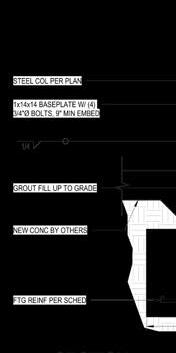
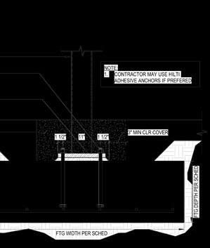
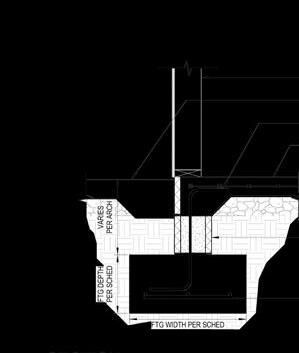
PAGE 29 SCOPE OF WORK: 3' 4'-6" 4' 1'-10" 4'-6" FRAME SIZE ROUGH OPENING 35 1/2" 41 1/2" 36" 42" 35 1/2" 41 1/2" 36" 42" 71 1/2" 71 1/2" 72" 72" 80 21/64" x 68" 80 53/64" 68 1/2" 121 53/64" 68" 122 21/64" 68 1/2" 121 53/64 20 21/64 122 21/64 20 53/64 35 1/2" 59 1/2" 36" 60" 81 3/8" 20 21/64 81 7/8" 20 53/64" 29 1/2" 59 1/2" 30" 60" 29 1/2" 59 1/2" 30" 60" 83 1/2" 17 1/2" 84" x 18" 3'0" 6'8-3/4" 5'0" 6'8" 141" 79 1/2" 142" x 80" window stool to be WS414 Sheet of Description Approved Date REVISIONS Date Drawn: Designed By: Exhibit A in regards to the Construction Agreement Concept Dev. V.2 AM 11/13 Design Review #1 V.3 AM 12/23 OSEM V.4 AM 1/13 Design Review #2 V.5 AM 2/2 Final Construction Set V.6 AM 2/10 MAYWOOD_FANSHERBrad + Maggie Fansher 5001 Maywood Drive Nashville, TN 37211 1/8" = 1'-0" A101.5 MB 08/06/2020 Plot to full scale on 11x17 Sheet of Description Approved Date REVISIONS Date Drawn: Designed By: Exhibit A in regards to the Construction Agreement Brad + Maggie Fansher 5001 Maywood Drive Nashville, TN 37211 3/16" = 1'-0" 01 06 AM 06/22/2021 Plot to full scale on 11x17 PRELIMINARY DRAWINGS NOT FOR CONSTRUCTION 6x6 steel column 14" steel I-beam PT 2x6 Top Plate 2x12 cedar rafter as exposed tails - sistered onto 2x12 SYP rafters w/ cedar blocking to enclose ceiling cavity and cover framing slope @ end to be cut to match house roof slope 5/8" OSB roof decking for EPDM rubber roof with 1/4":12" slope **5/8 nickle gap @ exposed soffit in place of decking** NON-SHRINK GROUT TOP OF STEEL TOP OF GUTTER 142-3/8" 101-1/2" 0'-0" TOP OF FOOTER @ FRONT 30-5/8" TOP OF STEEL TOP OF GUTTER 111-7/8" 101-1/2" 0'-0" TOP OF FOOTER @ REAR 44-5/8" Description Approved Date REVISIONS Date Drawn: Designed By: Exhibit A in regards to the Construction Agreement Brad + Maggie Fansher 5001 Maywood Drive Nashville, TN 37211 3/16" = 1'-0" AM 06/22/2021 Plot to full scale on 11x17 PRELIMINARY DRAWINGS NOT FOR CONSTRUCTION TOP OF STEEL TOP OF GUTTER 142-3/8" 101-1/2" 0'-0" TOP OF FOOTER @ FRONT 30-5/8" TOP OF STEEL TOP OF GUTTER 111-7/8" 101-1/2" 0'-0" TOP OF FOOTER @ REAR 44-5/8" Sheet of Description Approved Date REVISIONS Date Drawn: Designed By: Exhibit A in regards to the Construction Agreement Brad + Maggie Fansher 5001 Maywood Drive Nashville, TN 37211 3/16" = 1'-0" 04 06 AM 06/22/2021 Plot to full scale on 11x17 PRELIMINARY DRAWINGS NOT FOR CONSTRUCTION Merrill Construction Group P.O. Box 150365 Nashville, TN 37215 www.merrillconstructiongroup.com Page 5 11.02 New Addition Construct floor system of new addition Construct exterior and interior walls of addition Construct ceiling system of new addition Construct roof system – slope/shape to match existing hip roof Frame for new skylight opening - need curb on skylight to be installed on EPDM flat roof (see roofing specification for details, get specs from roofer on curb need for this skylight) Frame out all new window + door openings @ addition Frame out Dutch Pocket door at mudroom entry from master bedroom Frame out new stoop for new exterior entry @ addition **Exterior storage room to be left unfinished To remain @ grade level w/ concrete floor** 11.03 Blocking Install blocking where bath accessories to be installed in master bath Install blocking where cabinetry to be installed in kitchen, mudroom, + master bath Install blocking @ exterior storage room for new utility shelving on walls 12 ROOFING 12.01 New roof structure @ Addition Install new hip roof structure @ addition (hip slopes to match existing @ house) Shingle
Box 150365 Nashville, TN 37215 www.merrillconstructiongroup.com Page 10 Island: - WALNUT BUTCHER BLOCK - 2” thick standard eased edge - Conversion Varnish 27.02 Mudroom + Master Bath Countertops **ALL COUNTERTOPS TO BE PROVIDED + INSTALLED BY KIGHT CABINETS** Mudroom + Master Bath: - SOUTHERN STONE - PACIFICA GRAVITAS - No backsplash/sidesplash - Standard Eased Edge Profile **CLIENT TO APPROVE PACIFICA GRAVITAS SLAB IN PERSON PRIOR TO PURCHASING** 28 TILE 28.01 Tile Installation: Kitchen Install tile @ Kitchen backsplash (approx.. 60 SF): - Perimeter kitchen walls from countertop to ceiling - Wet Bar kitchen wall from countertop to BOTTOM of floating shelf TEC ARTE – YESO COLLECTION Size: 5” x 5” Field Tile + ½” x 5” Quarter Round (at windows) Color: Matte Green Pattern: Stacked Grout: Laticrete Natural Grey – Sanded 28.02 Tile Installation: Mudroom Install tile @ mudroom backsplash (approx. 36 SF): - Washer and dryer wall ONLY ANDALUCIA – TERRA COTTA TILE Size: 2” x 6” Field Tile Color – Atlantico – Matte Pattern: Stacked – Horizontal Grout: Laticrete Raven – Sanded 28.03 Tile Installation: Master Bathroom No curb @ shower – slope to linear drain @ back wall Provide + Install Linear Drain @ Master Bath Shower Back Wall Install Tile @ Master Bath Floor, Shower Floor + Back wall of shower (approx. 190 SF) Install Tile @ side walls of shower (approx. 140 SF) - On master bedroom side tile to stop @ end of shower - On vanity wall tile to continue along entire wall behind vanity ANDALUCIA – TERRA COTTA TILE Size: 2” x 6” Field Tile + 2” x 6” Bullnose on short side (approx. 15 LF) Color: Marino – Matte Pattern: Stacked – Vertical Grout: Laticrete Light Pewter – Sanded Location: Bath Floor, Shower Floor, Shower Ledge/Back wall of Shower LOVE AFFAIRS – CONCRETE TILE Size: 4” x 20” Field Tile Color: Light Grey Pattern: Stacked – Horizontal Grout: Laticrete Light Pewter – Sanded Location: Shower Side Walls + Full Vanity Wall
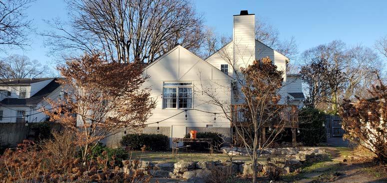
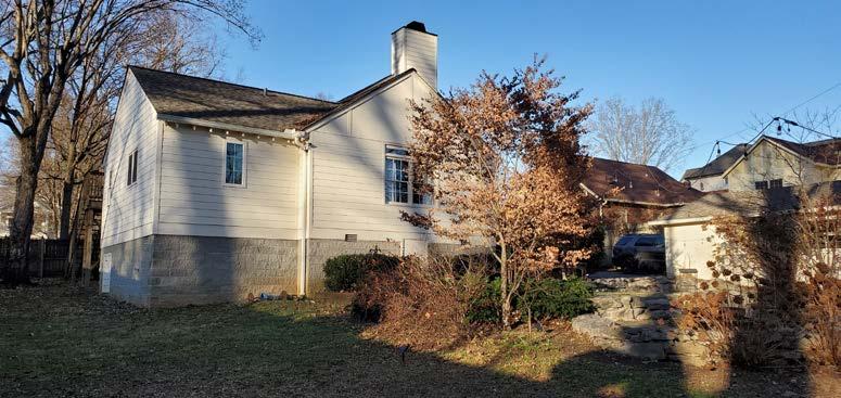
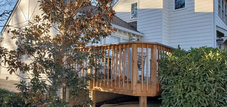
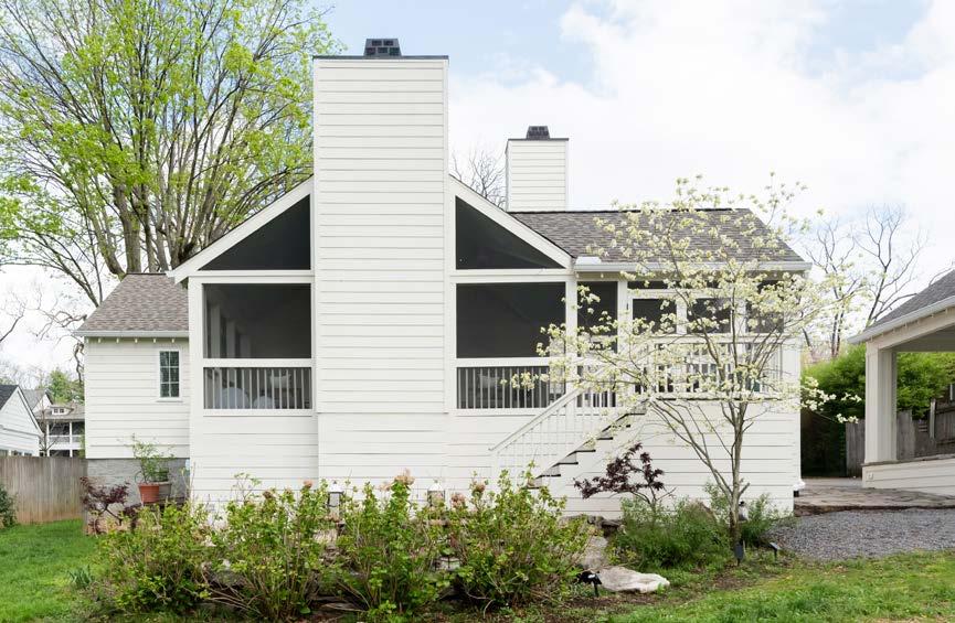
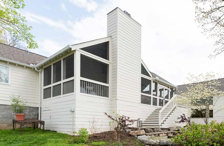
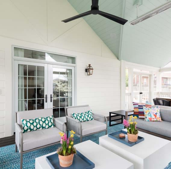
Merrill Construction Group Nashville, TN
This was a repeat client for the company I worked for. For this project, they wanted to add a screen porch to the back side of their house to upgrade their outdoor living space. We wanted to maximize natural light and keep everything as open as possible. They key to this was vaulting the ceilings of the porch roof to make the space feel larger and adding in screen panels to the gable ends to maximize that open feeling. We added in ceiling fans, as well as, a fireplace and outdoor heaters that dropped from the ceiling to ensure this porch could comfortably be used yearround. SKILLS:
• AutoCAD
PAGE 30 3068(2) 3068(2) W/ TRANSOM EXISTING DECK EXISTING MASTER BEDROOM SLOPE 12 SLOPE 8 12 NEW SCREENED PORCH APPROX 490 S/F (vaulted ceiling to match existing roof slope no collar ties) 3068(2) 33'-8" 15'-7 1 2 6'-6" 12'-5" corner posts to be 8x8 typ. middle posts to be 6x6 typ deck boards to extend past posts 4-1/2" see page D101.1 Detail #02 approx. location of stairs shown exact location to be FIELD VERIFIED stair treads to end existing patio edge 7 4 4'-6 4 5 2 4'-5 2 5 2 4'-6 1 4 7 4 7 4 2'-1 4 5 2 6'-1" 5 2 2'-1 7 4 DOUBLE SCREEN DOORS 6/0 6/8 R.O. 6'1" 6'9" DOUBLE SCREEN DOORS 6/0 6/8 4 2'-1 4 5 2 6'-1" 4'-0 3 4 5 2 2'-8 2 7 4 6'-03 8 5 2 8 6'-10 2 8 6'-03 8 7 4 4'-4" 5 2 4'-2 2 5 1 2 4'-4" 1'-9 1 2 9 4 1'-11 3 4 3'-2 2 42"W Wood Burning Fireplace R.O. 51-5/8" x 74" STRUCTURAL RIDGE STRUCTURAL RIDGE TIE INTO EXISTING DOWNSPOUT NEW DOWNSPOUT 35" 3068 7'-33 4 TIE INTO EXISTING DOWNSPOUT LEAVE 1-1/8" SPACE BETWEEN FRAMING FOR FIREPLACE CHIMNEY + 6X6 POST CHIMNEY VENEER TO CONTINUE BEHIND POST (SEE DETAILS ON PAGE D101.2) STRUCTURAL RIDGE TO BE EXPOSED STARTING AT VALLEY IN ROOF WRAP BEAM IN TRIM MATERIAL (SEE DETAIL) PAINTED TO MATCH CEILING SEE DETAILS ON PAGE D101.1 FAUX BEAM TO MIMIC STRUCTURAL BEAM FAUX BEAM TO MIMIC STRUCTURAL BEAM PLACE GAS CHEATER KEY ON RIGHT SIDE OF FIREPLACE CHIMNEY SURROUND Sheet of Description Approved Date REVISIONS Date Drawn: Designed By: Exhibit A in regards to the Construction Agreement Concept Review Notes V.2 AM 12/20 Notes from Designer V.3 AM 1/6 Drawing Revisions DetailsV.4 AM 1/28 Construction SetV.5 AM 1/30 Final Drawing Set V.7 AM 2/5 CLAYTON_WARFIELD II MIles + Susannah Warfield 907 Clayton Ave Nasvhille, TN 37204 1/4" = 1'-0" 02 16 A101.1 AM 12/6/19 Plot to full scale on 11x17 LEGEND LIGHT SWITCH WALL OUTLET SINGLE WALL SCONCE CEILING FAN 2700K LED RECESSED CAN EXTERIOR BUBBLE GFI FLOOD LIGHT DUPLEX RECESSED FLOOR OUTLET CABLE TV GFI plug in soffit existing floor register to remain approx locations exact location of heaters TBD on site GFI plug in soffit GFI plug in soffit GFI plug in soffit 3-way Dimmer 3-way each heater to have independent switch switch to control soffit GFI plugs GFI @ underpinning GFI @ underpinning include switch @ crawl access door include lights underneath deck 3068(2) 3068(2) W/ TRANSOM EXISTING DECK EXISTING MASTER BEDROOM SLOPE 12 SLOPE 12 NEW SCREENED PORCH APPROX 490 S/F (vaulted ceiling to match existing roof slope no collar ties) 3068(2) R.O. 6'1" X 6'9" DOUBLE SCREEN DOORS 6/0 X 6/8 R.O. 6'1" X 6'9" DOUBLE SCREEN DOORS 6/0 X 6/8 42"W Wood Burning Fireplace STRUCTURAL RIDGE STRUCTURAL RIDGE 35" 3068 tie into existing sconce existing switching @ interior of house fan rio-stat switch (hi-med-lo speed control) fan rio-stat switch (hi-med-lo speed control) Description Approved REVISIONS Date Drawn: Designed By: Exhibit A in regards to the Construction Agreement Concept Review NotesV.2 AM Notes from DesignerV.3 AM Drawing RevisionsDetails V.4 AM Construction Set V.5 AM Final Drawing Set V.7 AM CLAYTON_WARFIELD II MIles + Susannah Warfield 907 Clayton Ave Nasvhille, TN 37204 AM 12/6/19 Plot to full scale on 11x17
SCREEN PORCH ADDITION
PROPOSED FLOOR PLAN: EXTERIOR ELEVATIONS: FRAMING PLANS:
FINISH HEIGHT FINISH FLOOR TO MATCH EXISTING DECK ELEVATION MATCH EXISTING 8' TOP OF DOOR MATCH EXISTING 6'-8" 6'-6" 15'-9" chimney cap painted to match existing high-temp black match soffit + fascia detail of existing house (leave rafter tails) See Detail #01 on page D101.1 underpinning to be horizontal PT 2x8's CONTINUE DETAIL @ FIREPLACE CHIMNEY BELOW DRIP CAP 3-1/2" Corner Boards chimney surround to be 8" HARDI Board ABOVE DRIP CAP REVEAL TO MATCH EXISTING CHIMNEY @ HOUSE 6'-11 5 8 5 1 2 6'-11 5 8 7 4 7 1 4 71 4 5'-4 2 5 2 5'-113 4 7 4 " 6'-03 8 5 2 " 2X12 LEDGER BOARD (25) 2X10 JOISTS @ 16' 6X6 GRADE TO RACK 16' 8X8 GRADE TO RACK FLUSH 6X6 GRADE TO BAND 16' 8X8 GRADE TO RACK FLUSH 6X6 GRADE TO BAND 16' 8X8 GRADE TO RACK FLUSH 6X6 GRADE TO BAND (TIE INTO EXISTING DECK) FLUSH 6X6 GRADE TO BAND DOUBLE 2X12 BAND AROUND PERIMETER (OUTSIDE OF POSTS) 7 4 5'-4 2 51 2 5'-113 4 5 2 WRAP ALL POSTS @ DECK LEVEL WITH PT DEADWOOD TO SECURE DECK BOARD ATTACHMENT 4X4 POSTS TO FINISH @ TOP OF JOISTS DIRECTLY BENEATH KING STUDS FOR FIREPLACE HEADER TO SUPPORT WEIGHT OF STRUCTURAL RIDGE 16' 8X8 GRADE TO RACK 6X6 DECK TO RACK (32) 2X8 RAFTERS @ 16" O.C. 6X6 DECK TO RACK 16' 8X8 GRADE TO RACK 16' 6X6 GRADE TO RACK 6X6 DECK TO RACK 16' 8X8 GRADE TO RACK 6X6 DECK TO RACK 6X6 RACK TO LVL RIDGE STRUCTURAL RIDGE: 2X10 LVL CONTINUE TO OPPOSITE GABLE END TIE INTO RAFTERS ON PLAN EAST SIDE 2X8 RACK PACKED OUT WITH OSB 2X8'S TO SIT FLUSH WITH 6X6's 8X8's SIT PROUD @ CORNERS 6X6 DECK TO RACK 6X6 DECK TO RACK 8X8 DECK TO RACK 2X10 VALLEY RAFTER
ELECTRICAL FLOOR PLAN:

PAGE 31 19' 21' Sheet of Description Approved Date REVISIONS Date Drawn: Designed By: Exhibit A in regards to the Construction Agreement Concept Review NotesV.2 AM 12/20 Notes from DesignerV.3 AM 1/6 Drawing Revisions Details V.4 AM 1/28 Construction SetV.5 AM 1/30 Final Drawing Set V.7 AM 2/5 CLAYTON_WARFIELD II MIles + Susannah Warfield 907 Clayton Ave Nasvhille, TN 37204 1/4" = 1'-0" 07 16 E101.2 AM 12/6/19 Plot to full scale on 11x17 8 8 " 5 2 " 6'-03 8 71 4 " 7 2 76'-7 8 5 2 76'-7 8 7 1 2 LEAVE 1-1/8" SPACE BETWEEN FRAMING FOR FIREPLACE CHIMNEY 6X6 POST CHIMNEY VENEER TO CONTINUE BEHIND POST (SEE DETAILS ON PAGE D101.2) 16' 8X8 GRADE TO RACK FLUSH 6X6 GRADE TO BAND 16' 8X8 GRADE TO RACK 16' 6X6 GRADE TO RACK 16" O.C. 1'-0 16 11 1 4 11 1 4 1'-0 16 " 1'-5 4 1'-8 3 4 Approved Date Drawn: Designed By: Exhibit A in regards to the Construction Agreement AM AM AM AM AM CLAYTON_WARFIELD II MIles + Susannah Warfield 907 Clayton Ave Nasvhille, TN 37204 AM 12/6/19 Plot to full scale on 11x17 (30) 2X8 RAFTERS @ 16" O.C. 16' 6X6 GRADE TO RACK 16' 8X8 GRADE TO RACK STRUCTURAL RIDGE: 2X10 LVL 16' 8X8 GRADE TO RACK 6X6 DECK TO RACK 6X6 DECK TO RACK 2X8 RAFTERS DOUBLED ON EITHER SIDE TO SUPPORT RIDGE USE LAG BOLTS TO SECURE LVL Sheet of Description Approved Date REVISIONS Date Drawn: Designed By: Exhibit A in regards to the Construction Agreement Concept Review NotesV.2 AM 12/20 Notes from DesignerV.3 AM 1/6 Drawing RevisionsDetails V.4 AM 1/28 Construction SetV.5 AM 1/30 Final Drawing Set V.7 AM 2/5 CLAYTON_WARFIELD II MIles + Susannah Warfield 907 Clayton Ave Nasvhille, TN 37204 1/4" = 1'-0" 04 16 A101.3 AM 12/6/19 Plot to full scale on 11x17 SECTIONS: DETAILS: FINISH HEIGHT FINISH FLOOR TO MATCH EXISTING DECK ELEVATION MATCH EXISTING 8' TOP OF DOOR MATCH EXISTING 6'-8" 33'-8" 21'-3" 5' 8' 3' 12'-5" chimney cap painted to match existing high-temp black match soffit + fascia detail of existing house (leave rafter tails) See Detail #01 on page D101.1 underpinning to be horizontal PT 2x8's CONTINUE DETAIL @ FIREPLACE CHIMNEY BELOW DRIP CAP 3-1/2" Corner Boards chimney surround to be 8" HARDI Board ABOVE DRIP CAP REVEAL TO MATCH EXISTING CHIMNEY @ HOUSE Drip Cap @ new screened porch finish elevation Below 2x8 underpinning to continue around Above 8" Hardi Board (reveal to match house) 21' 19' Sheet of Description Approved Date REVISIONS Date Drawn: Designed By: Exhibit A in regards to the Construction Agreement Concept Review Notes V.2 AM 12/20 Notes from Designer V.3 AM 1/6 Drawing Revisions Details V.4 AM 1/28 Construction SetV.5 AM 1/30 Final Drawing Set V.7 AM 2/5 CLAYTON_WARFIELD II MIles + Susannah Warfield 907 Clayton Ave Nasvhille, TN 37204 1/4" = 1'-0" 06 16 E101.1 AM 12/6/19 Plot to full scale on 11x17 8' 10" vertical planks w/ 1/8" reveal (pre-primed 1x10's) LINE UP VERTICALS ON FIREPLACE CHIMNEY, SURROUND HEARTH 3'-2 1 2 top rail @ screen porch to line up with existing deck railing approx. 38-1/2" AFF Fireplace Hearth to be Honed Black Pearl Granite (Mitered to appear 2" thick around perimeter) Fireplace Surround to be: Honed Black Pearl Granite installed flush with vertical planks (MAXIMUM OF 1/2" REVEAL) HEATERS TO REMAIN AT SAME ELEVATION ACROSS SPACE FINAL HEATER LOCATION TBD ON SITE AT TIME OF COMPLETED ROOF FRAMING band to be double 2x12's on outside of deck posts (NOT NOTCHED IN) See detail #02 on page D101.1 underpinning to be PT 2x8's 6x6 centered @ gable end to support structural ridge + catch screen battens wrap with 1x trim material 2x8 rack notched into posts (pack out to match width of 6x6 posts 2x8+OSB) wrap with 1x trim material STRUCTURAL RIDGE: 2x10 LVL interior finished with 3/4" V-Groove STRUCTURAL RIDGE: 2X10 LVL 2X8 rafters interior finished with 3/4" beadboard (installed with v-groove exposed) 1x6 fascia board (match existing house) LEAVE EXPOSED RAFTER TAILS See Detail #01 on page D101.1 6'-8" 13' 6' 33'-8" 1' 2" 2'-6" 1' STRUCTURAL RIDGE: 2X10 LVL to continue into opposite end rafters support with doubled 2x8 rafters on both sides lag-bolted together where exposed trim out with 1x material SEE DETAIL #03 ON PAGE D101.1 PLACE GAS CHEATER KEY ON RIGHT SIDE OF FIREPLACE CHIMNEY SURROUND Description Approved REVISIONS Date Drawn: Designed By: Exhibit A in regards to the Construction Agreement Notes V.2 AM Designer V.3 AM Revisions DetailsV.4 AM V.5 AM V.7 AM CLAYTON_WARFIELD II MIles + Susannah Warfield 907 Clayton Ave Nasvhille, TN 37204 AM 12/6/19 Plot to full scale on 11x17 2x2 batten 1x batten 2x8 rack (notched into post) pack out with 2x8 + OSB to line up in between 6x6 posts trim out with 1x material 2x8 rafter 1x6 fascia board 3/4" V-Groove Beadboard Description Approved REVISIONS Date Drawn: Designed By: Review NotesV.2 AM from DesignerV.3 AM RevisionsDetailsV.4 AM Construction SetV.5 AM CLAYTON_WARFIELD II MIles + Susannah Warfield 907 Clayton Ave Nasvhille, TN 37204 AM 12/6/19 Plot to full scale on 11x17 Double band 2x12's (outside of posts) 4-1/2" 1-1/2" 1x4 batten 2x4 screen 2x2 baluster 1x4 1x6 batten 2x6 top rail 2x2 batten 1x batten 2x8 rack (notched into post) pack out with 2x8 + OSB to line up in between 6x6 posts trim out with 1x material 2x8 rafter 1x6 fascia board 3/4" V-Groove Beadboard Structual Ridge 9-1/4" LVL 2x8 Rafters 3/4" V-Groove Bead Board Ceiling (installed v-groove exposed) 1x Material to Trim Out Exposed Ridge Structural Ridge from adjacent gable roof to continue into rafters on plan east side of ridge Double 2x8's on either side to support continued ridge anchored together with lag bolts 1x Material to Trim Out Exposed Ridge 3/4" V-Groove Bead Board Ceiling (installed v-groove exposed) 2x10 Structural Ridge Doubled 2x4's to continue down to fireplace header to support structural ridge Typ. 2x4 wall construction for chimney @ 16" O.C 2x6 fireplace header (placed @ 74" AFF - to be packed down after firebox installation Doubled jack studs @ fireplace header Fireplace R.O - 51-5/8" x 74" add 2x blocking where structural ridge dies into studs/rafters wrap in 1x material 2x10 LVL (middle beam) 2x10's (faux beams) 1/2" OSB 2x4 2x8's w/ 1/2 Double (outside 4-1/2" 1-1/2" 1x4 2x4 screen 2x2 1x4 1x6 2x6 STRUCTURAL RIDGE: 2X10 LVL to continue into opposite end rafters support with doubled 2x8 rafters on both sides lag-bolted together ADD (2) FAUX BEAMS TO MIMIC FINISH OF STRUCTURAL LVL (1) EITHER SIDE OF LVL where exposed trim out with 1x material SEE DETAIL #03 ON PAGE D101.1 top rail @ screen porch to line up with existing deck railing approx. 38-1/2" AFF FINISH HEIGHT FINISH FLOOR TO MATCH EXISTING DECK ELEVATION MATCH EXISTING 8' TOP OF DOOR MATCH EXISTING 6'-8" TOP OF RIDGE MATCH EXISTING RIDGE HEIGHT 67 8 11 1 4 7 8 67 8 2'-10" 2'-10" repair trim pieces @ gable end of existing house (bondo repaint) Sheet of Description Approved Date REVISIONS Date Drawn: Designed By: Exhibit A in regards to the Construction Agreement Concept Review Notes V.2 AM 12/20 Notes from Designer V.3 AM 1/6 Drawing Revisions Details V.4 AM 1/28 Construction Set V.5 AM 1/30 Final Drawing Set V.7 AM 2/5 CLAYTON_WARFIELD II MIles + Susannah Warfield 907 Clayton Ave Nasvhille, TN 37204 1/4" = 1'-0" 11 16 E101.5 AM 12/6/19 Plot to full scale on 11x17 FINISH HEIGHT FINISH FLOOR TO MATCH EXISTING DECK ELEVATION MATCH EXISTING 8' TOP OF DOOR MATCH EXISTING 6'-8" match soffit fascia detail of existing house (leave rafter tails) See Detail #01 on page D101.1 underpinning to be horizontal PT 2x8's tie into existing deck underpinning to continue @ existing deck band 19' Sheet of Description Approved Date REVISIONS Date Drawn: Designed By: Exhibit A in regards to the Construction Agreement Concept Review Notes V.2 AM 12/20 Notes from Designer V.3 AM 1/6 Drawing Revisions DetailsV.4 AM 1/28 Construction Set V.5 AM 1/30 Final Drawing Set V.7 AM 2/5 CLAYTON_WARFIELD II MIles + Susannah Warfield 907 Clayton Ave Nasvhille, TN 37204 1/4" = 1'-0" 08 16 E101.3 AM 12/6/19 Plot to full scale on 11x17 FINISH HEIGHT FINISH FLOOR TO MATCH EXISTING DECK ELEVATION MATCH EXISTING 8' TOP OF DOOR MATCH EXISTING 6'-8" match soffit (leave rafter See Detail exact size (DOUBLE chimney surround ABOVE DRIP REVEAL TO chimney cap high-temp underpinning PT 2x8's CONTINUE FIREPLACE BELOW DRIP Drip Cap @ Below 2x8 Above 8"

PAGE 32
BEFORE CONSTRUCTION: AFTER CONSTRUCTION:
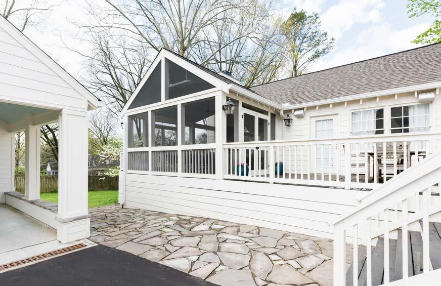
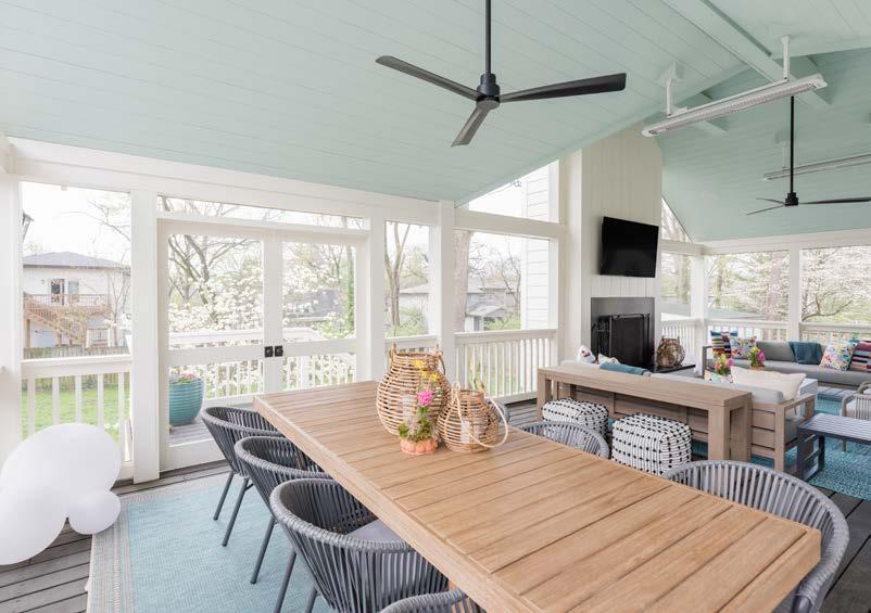
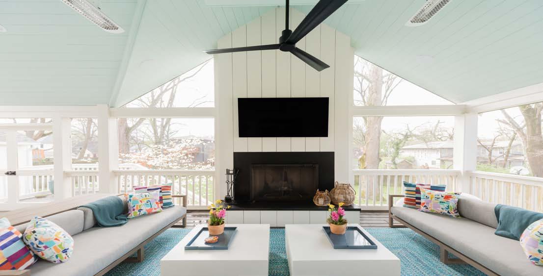
All final photography + edits are credited to Ruby + Peach Photo (Nashville, TN)
SECOND STORY ADDITION
Another repeat client for the company. This family had recently grown by two, and were finding that their existing space was not conducive for their large family. They wanted to add an upstairs addition to their existing house that could
operate as the “kids area” so that the downstairs could return to being more adult/ family oriented. We were able to provide each kid their own bedroom, as well as, a large playroom upstairs that increased the family’s storage
capability tenfold. We were also able to upgrade the master suite and mudroom, add a powder room downstairs, and convert one of the bedrooms to a guest suite for when extended family came to visit.
EXTERIOR ELEVATIONS:
PAGE 34
SKILLS: • AutoCAD Merrill
Approved Date Drawn: Designed By: Exhibit A in regards to the Construction Agreement am Description Approved Date REVISIONS Date Drawn: Designed By: Exhibit A in regards to the Construction Agreement Concept Drawings Round 2 am 12/15
Construction Group | Nashville, TN
PAGE 35 Approved Date Drawn: Designed By: Exhibit A in regards to the Construction Agreement am Description Approved Date REVISIONS Date Drawn: Designed By: Exhibit A in regards to the Construction Agreement Concept Drawings Round 2 am 12/15 Sheet of Description Approved Date REVISIONS Date Drawn: Designed By: Exhibit A in regards to the Construction Agreement Concept Drawings Round 2 am 12/15 02 10 REVISIONS Designed By:
FIRST FLOOR PLAN: SECOND FLOOR PLAN:
BATH
STAIRCASE DETAIL:
MASTER
DETAILS:
WHOLE HOUSE REMODEL
Merrill Construction Group Nashville, TN
For this project, the space had been neglected for many years and was in dire need of upgrades and overall maintenance. Additionally, we would be converting the existing downstairs bedroom + bathroom into a more ADA compliant space for the aging mother and revamping the upstairs to accommodate the daughter and two granddaughters that would be moving in. This included reconfiguring the kitchen to better suit the family and adding a laundry room on the first floor to bring it up from the basement. The clients also wished to create a nice outdoor space to sit and relax together that included a fence to keep in their dogs.
SKILLS:
• AutoCAD
PAGE 36 Sheet of Description Approved Date REVISIONS Date Drawn: Designed By: Exhibit A in regards to the Construction Agreement 01 10 Sheet of Description Approved Date REVISIONS Date Drawn: Designed By: Exhibit A in regards to the Construction Agreement 03 10
EXISTING FIRST FLOOR: EXISTING SECOND FLOOR: PROPOSED FIRST FLOOR: PROPOSED SECOND FLOOR:
PAGE 37 Sheet of Description Approved Date REVISIONS Date Drawn: Designed By: Exhibit A in regards to the Construction Agreement 04 10 Sheet of Description Approved Date REVISIONS Date Drawn: Designed By: Exhibit A in regards to the Construction Agreement 04 10 Exhibit A in regards to the Construction Agreement Exhibit A in regards to the Construction Agreement Sheet of Description Approved Date REVISIONS Date Drawn: Designed By: Exhibit A in regards to the Construction Agreement 04 10
KITCHEN ELEVATIONS: MASTER BATH ELEVATIONS:
GIRL’S BATH ELEVATIONS: MASTER BATH TUB:
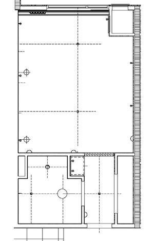
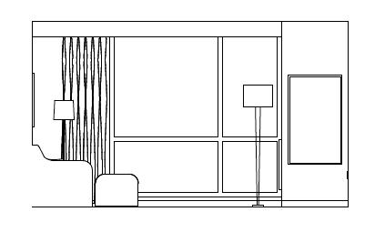
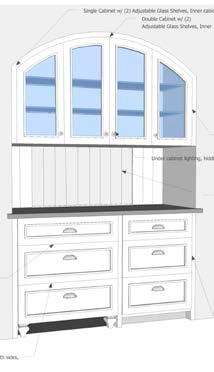
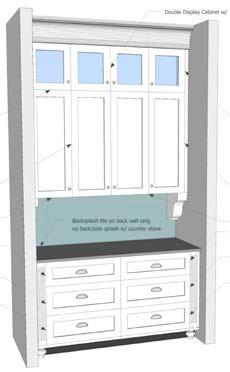
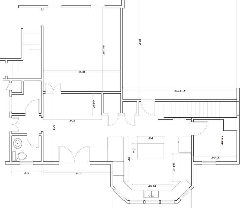
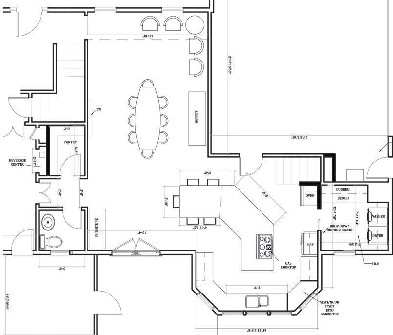
KITCHEN REMODEL
Weidmann & Associates | Atlanta, GA
For this client we were presented with everything she did not like about her current kitchen and tasked with designing a space that would accommodate all of her needs but still remain completely functional for her lifestyle.
We re-configured her pantry space and created a new island area. The bay window was converted into a banquet for her kitchen table. We incorporated an opening from the main kitchen area into the pantry,
as well as, through the bar area. A butlers pantry next to her dining room was also included in the redesign of the space to add functional circulation through to the dining room.
SKILLS:
• AutoCAD
• SketchUp
• Adobe InDesign
EXISTING + ELECTRICAL PLANS:
FINAL PROPOSED FLOOR PLAN:
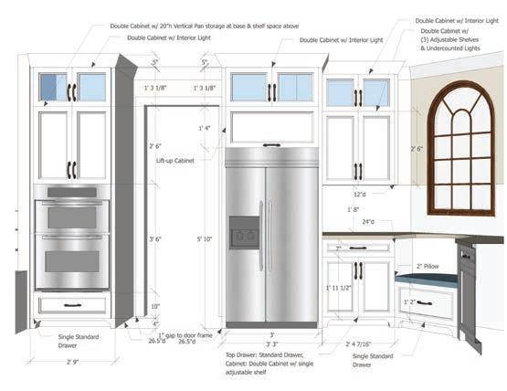
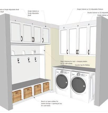
PAGE 39 RENDERED ELEVATIONS:
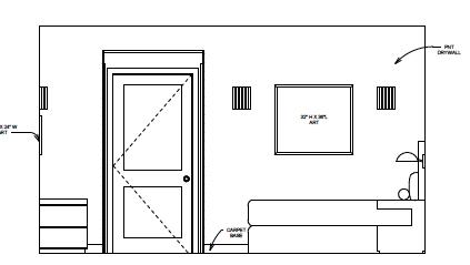
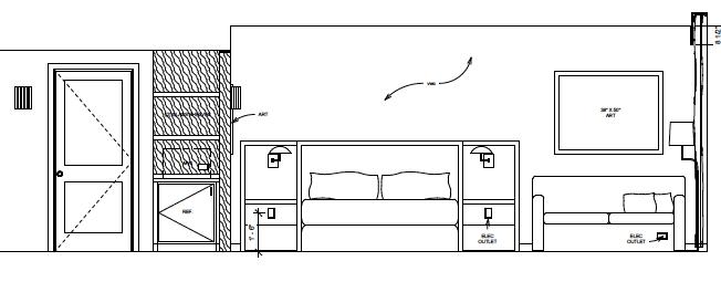
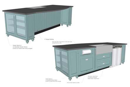
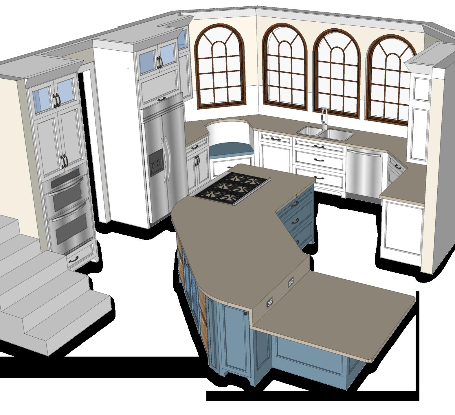
KITCHEN REMODEL
Weidmann & Associates Atlanta, GA
Another complete kitchen remodel located in Atlanta, GA. This client needed more space to accommodate her growing family and busy lifestyle. To achieve this we omitted the wall separating the dining room from the kitchen. This allowed for us to create a large island with a nice open dining room space. By re-spatial planning the existing space, we were able to achieve a much larger feeling kitchen space without actually extending the square footage, this way we could still keep the cost at a reasonable level.
SKILLS:
• AutoCAD
• SketchUp
• Adobe InDesign
PAGE 40
RENDERED ELEVATIONS:
PAGE 41 EXISTING FLOOR PLAN: PROPOSED FLOOR PLAN:
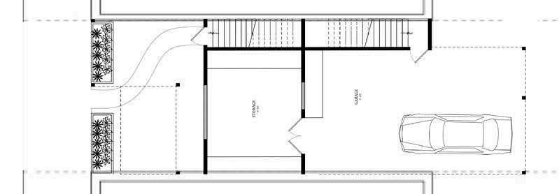
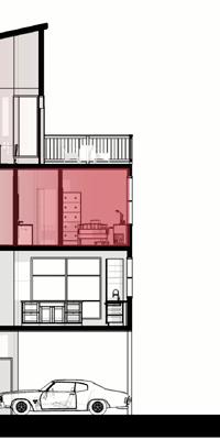
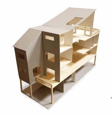
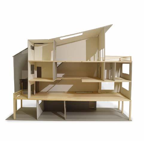
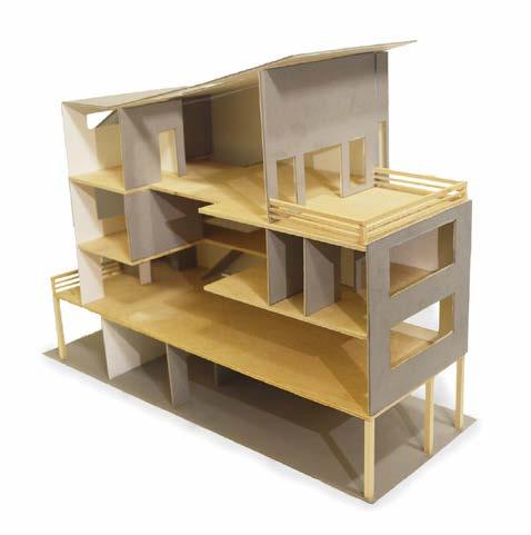
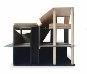
ROW HOUSE
University of Cincinnati Cincinnati, OH
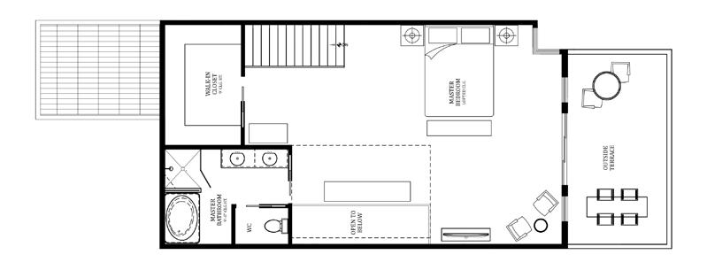
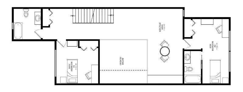
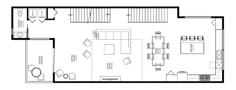
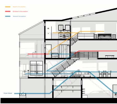
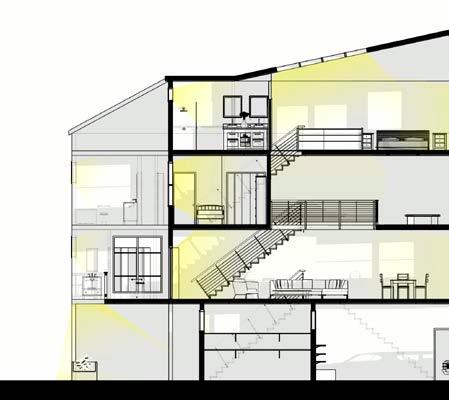
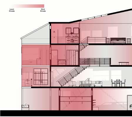
This project was based on a fictional site of multiple “Row Houses”, with the challenge being that the natural light was limited to the front and back of the house. I tried to maximize the functionality of the house, as well as, the overall light quality by including in-sets and “loft” spaced that would allow light to flood all through the home via a skylight. The house is separated into three floors + ground floor garage area. The first floor is a shared space for the whole family, while the second floor is primarily for the children, and the top floor is the “master suite” for the adults. SKILLS:
• AutoCAD
• SketchUp
• Adobe Photoshop
PAGE 42
FLOOR PLANS (top to bottom): SPATIAL DIAGRAMS:
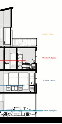
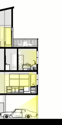
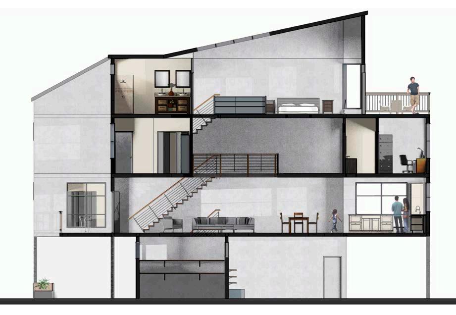
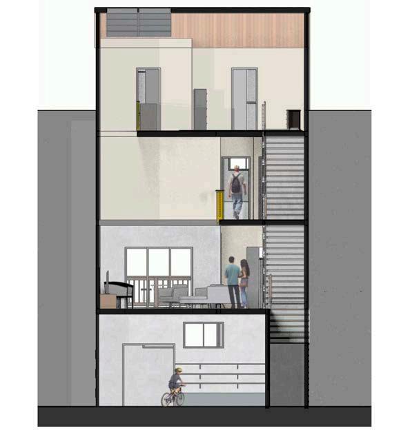
PAGE 43 RENDERED LONGITUDINAL SECTION:
RENDERED TRANSVERSE SECTION:
FULL BUILDING MODEL:
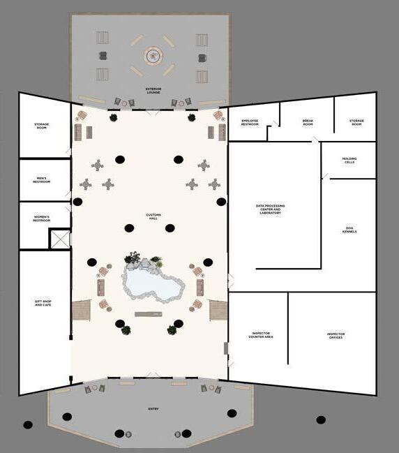
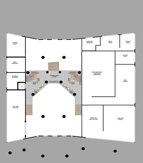
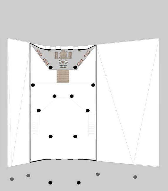
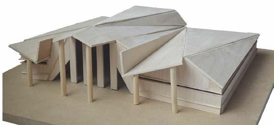
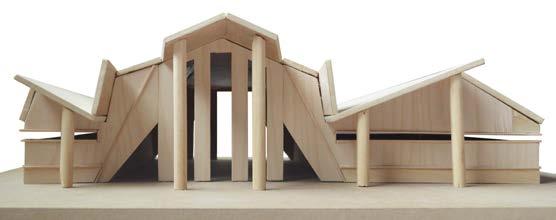
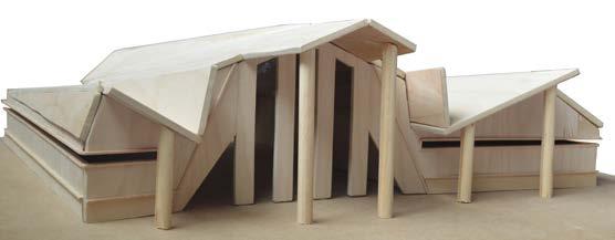
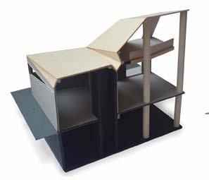
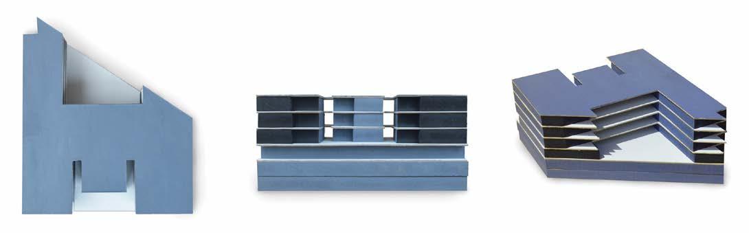
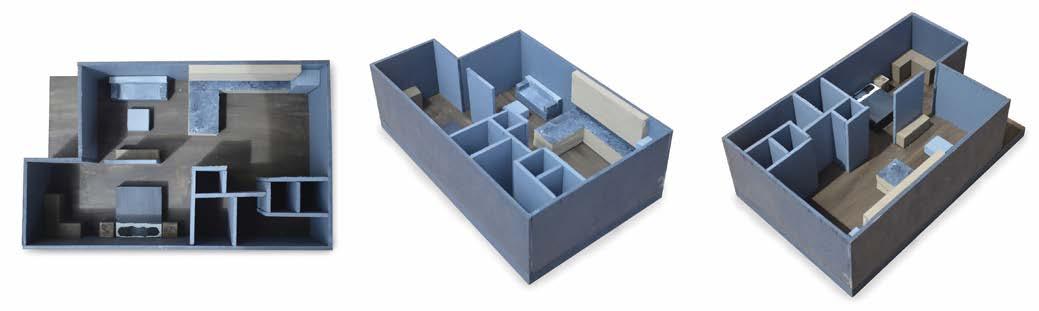
ALASKA + CANADA BORDER STATION
University of Cincinnati | Cincinnati, OH
This was final project of my fourth year at UC. We were tasked with choosing a border between two countries anywhere in the world and designing a Border Control Center to monitor people going across the chosen border.
I decided on the border of Alaska + Canada. The majority of travelers across this border are tourists driving The Alaska Highway and enjoying the sightseeing along the away. I wanted to provide an area for people to stop and rest before
continuing on their journey, The inspiration for my design was pulled from the mountain ranges surrounding the area. I wanted to keep an “outdoorsy” atmosphere of the region while also remaining peaceful, calm, and inviting.
SKILLS:
• AutoCAD
• SketchUp + Podium
• Adobe Photoshop
RENDERED FLOOR PLANS:
PAGE 44
Ground Floor Second Floor Third Floor
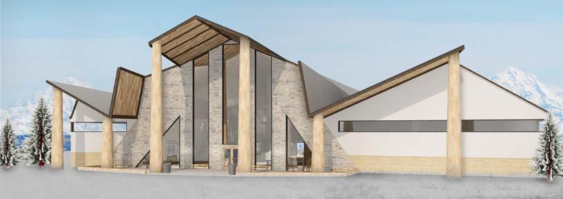
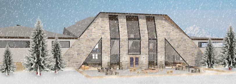
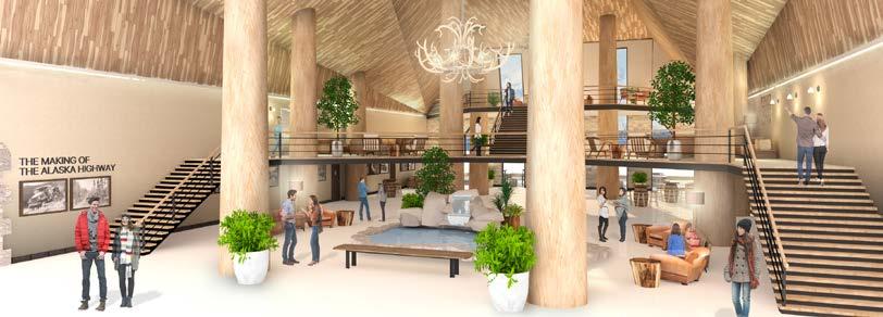
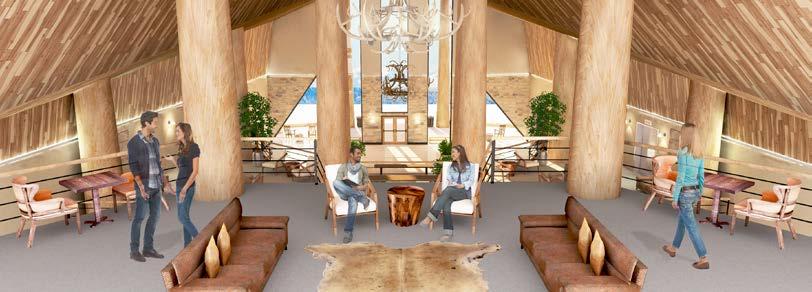
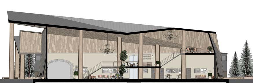

PAGE 45 RENDERINGS: LONGITUDINAL RENDERED SECTION:
FULL MODEL: SECTION MODEL:
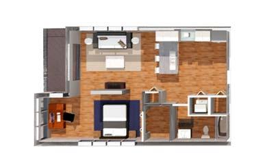
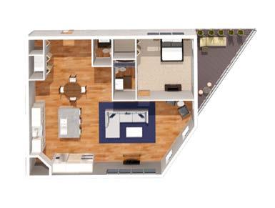
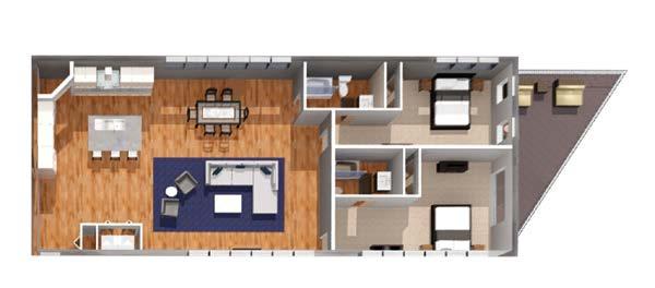
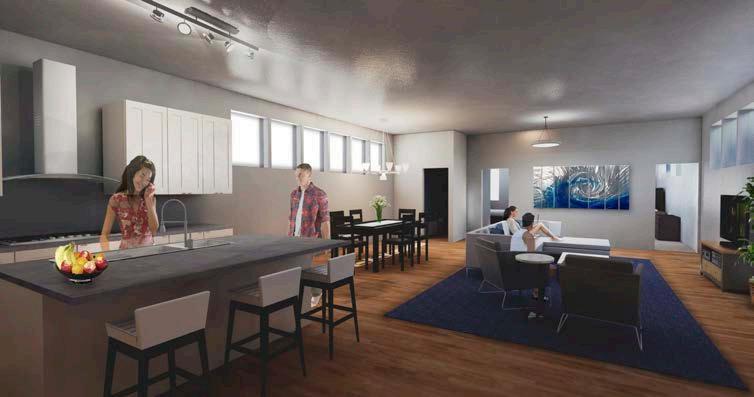
OVER-THE-RHINE HOUSING
University of Cincinnati | Cincinnati, OH
This was the final project of my third year at UC. We were given an empty site in Cincinnati’s own Over-TheRhine district. We were tasked with developing an apartment complex that had between 1015 units that were appropriately
sized. My design included a lower level parking garage, 2 outside community areas equipped with grills, and an indoor community area with TV’s, pool tables, and a kitchenette. The complex included studio, one bedroom,
and two bedroom apartments. My main focus was to maximize the light allowed into the apartments, due to the close proximity of the surrounding buildings.
STUDIO UNIT MODEL:
PAGE 46
SKILLS: • AutoCAD • SketchUp + Podium • Adobe Photoshop Rendered Floor Plan: Typical Studio Unit: Typical One Bedroom Unit: Typical Two Bedroom Unit:
BUILDING
RENDERED UNIT FLOOR PLANS:
FULL
MODEL:
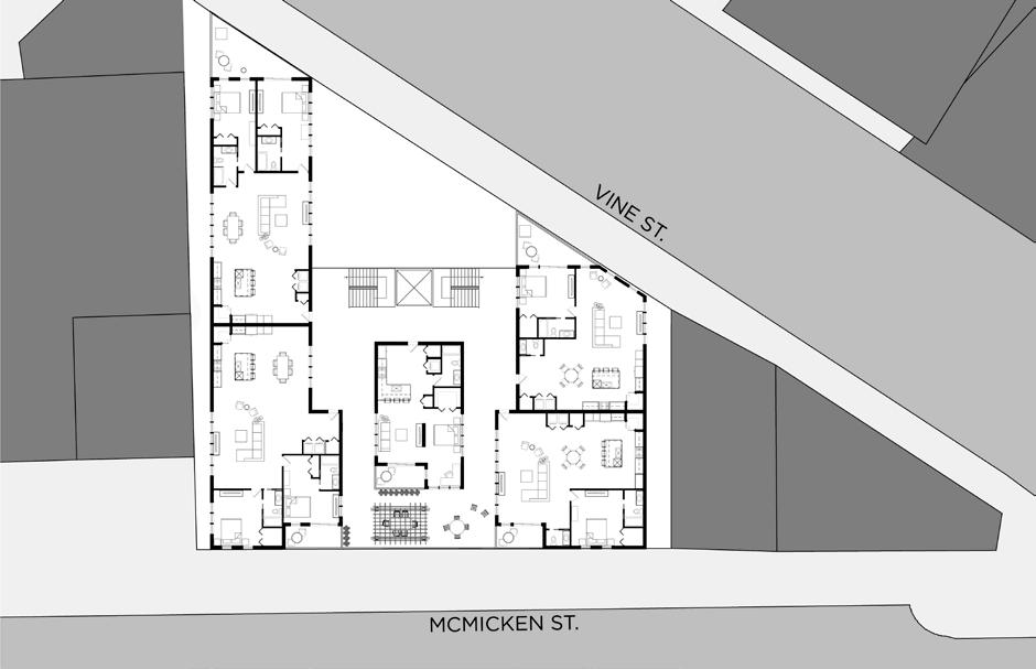
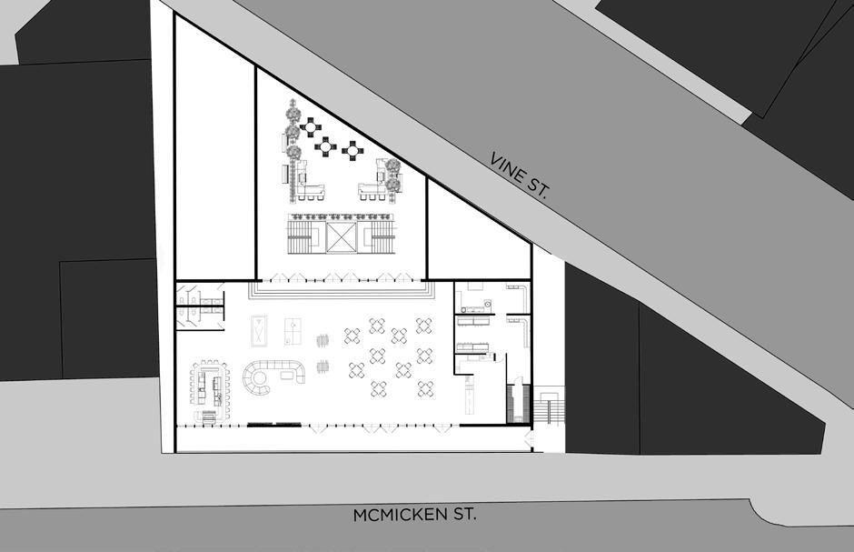
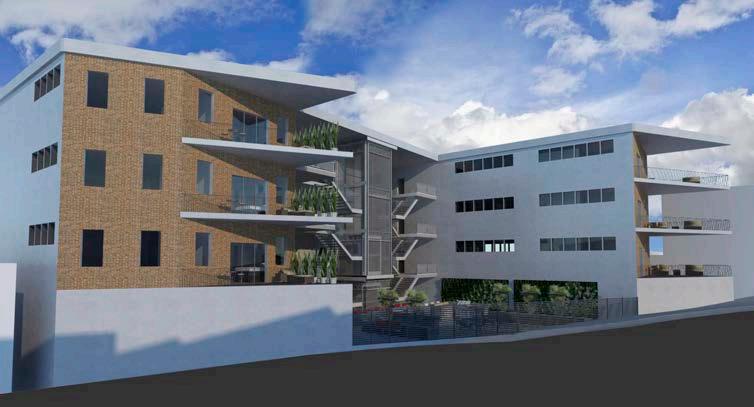
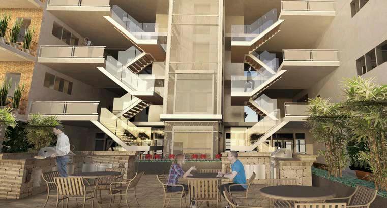
GROUND FLOOR + TYPICAL UNIT FLOOR PLANS: RENDERINGS:
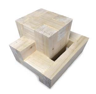
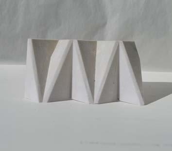
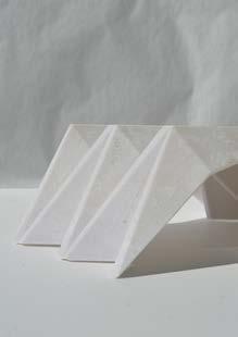
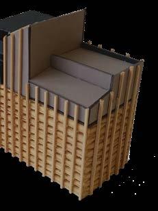
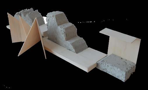
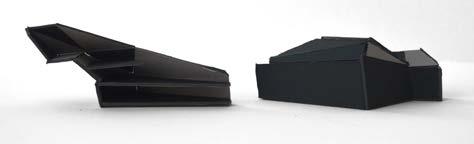
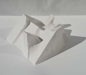
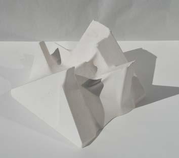
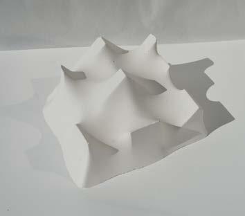
MODEL MAKING
MIXED MEDIA MODELS:
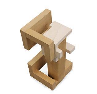
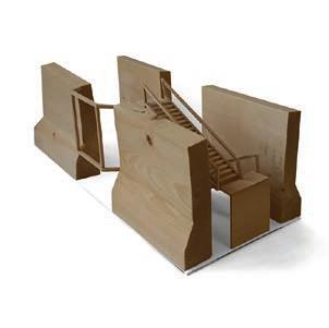

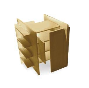


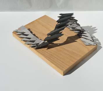


PAGE 48
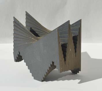
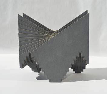
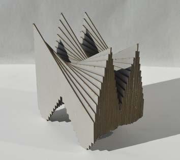
LASER CUT MODELS:
3D PRINT MODEL:


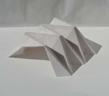
PAGE 49
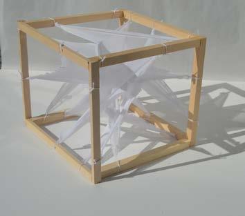
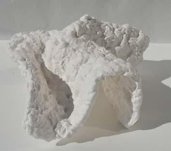
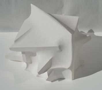
FABRIC MODEL: PLASTER MODELS:
THANK YOU FOR YOUR CONSIDERATION