

TABLE OF CONTENTS
ENVIRONMENTAL RESOURCE GUIDE 0
TABLE OF CONTENTS ................................................................................................................... 1
ENVIRONMENTAL DESIGN I ........................................................................................................... 4 module 1: foundations 5 module 2: principles .................................................................................................................. 8 module 3: climate 12 module 4: solar ........................................................................................................................ 15 module 5: energy ..................................................................................................................... 17 module 6: wind 20 module 7: envelope ................................................................................................................. 24 module 8: lighting .................................................................................................................... 26 module 9: materials ................................................................................................................. 30 module 10: site ......................................................................................................................... 37 module 11: water 41 module 12: synergies ............................................................................................................... 48 module 13: tools ....................................................................................................................... 50 module 14: assessments 55
ENVIRONMENTAL DESIGN II ........................................................................................................ 57 module 1: synergies ................................................................................................................. 58 module 2: hvac 64 module 3: lighting .................................................................................................................. 112 module 4: electricity 118 module 5: acoustics .............................................................................................................. 130 module 6: conveyance .......................................................................................................... 133 closing: design process 147 appendix: resources ................................................................................................................. 147
Page | 1

Page | 2
“As architects, we have an obligation to integrate ETHICS and METRICS symbiotically into a holistic sustainable design process. Understanding the principles of environmental science creates a solid basis for employi ng sustainable design”
- patricia andrasik

ENVIRONMENTAL DESIGN I
Page | 4
module 1: foundations
Review Definitions
Carbon Footprint: A measure of direct emission of gases that cause climate change – (for simplicity) the amount of carbon dioxide which is emitted.
Green House Gas: Any type of emission of gas which leads to the entrapment of infrared radiation which warms the planet. When there is more ‘greenhouse’ gas in the air, it holds more heat, which leads to global warming.
Global Warming: A gradual increase in the overall temperature of the earth's atmosphere generally attributed to the greenhouse effect caused by increased levels of carbon dioxide, chlorofluorocarbons, and other pollutants.
Up-cycling: To reuse, discard or otherwise recycle a material in order to create a higher quality product.
Integrated Design Process: A method of design in which multiple disciplines and seemingly unrelated aspects of design are integrated in a manner that permits synergistic benefits to be realized.
Net Zero Design: A building which produces as much energy as it uses over the course of a year, combining (1) exemplary (passive) building design to minimize energy requirements and (2) Renewable energy systems that meet these reduced energy needs.
Greenwashing: Greenwashing is mostly used as a term to describe the deceptive use of green PR or green appurtenances to promote a misleading perception that a building is environmentally friendly.
Rapidification: The continued acceleration of changes affecting humanity and the planet is coupled today with a more intensified pace of life and work.
Throwaway culture: human society strongly influenced by overconsumption of goods. The term describes a critical view of excessive production and items that are cradle-to-grave or disposable.
Down-cycling: When waste materials or useless products are converted into new materials or products of reduced functionality.
Environmental refugees: A society displaced by global warming impacts which directly affect their living environments.
Cradle to Cradle: C2C, cradle 2 cradle is an approach to the design of products and systems that models human industrial processes on nature ‘s. It assumes that materials circulate in healthy cycles and believes that industry must protect and enrich its ecosystems.
Page | 5
Theories:
History of Sustainability

-Sustainability isn’t a trend, or a cult, or a form of hysteria.
-It is rooted in American philosophy and being at once innovative and practical, idealistic and active, one could easily define modern environmentalism as quintessentially American.
Brundtland Report
Sustainable development is development that meets the needs of the present without compromising the ability of future generations to meet their own needs. It contains within it two key concepts: The concept of 'needs‘, in particular the essential needs of the world's poor, to which overriding priority should be given; and the idea of limitations imposed by the state of technology and social organization on the environment's ability to meet present and future needs.
Integrated Design process is a partnership of Ethics and Metrics

-According to an ongoing temperature analysis conducted by scientists at NASA’s Goddard Institute for Space Studies (GISS), the average global temperature on Earth has increased by about 0.8° Celsius (1.4° Fahrenheit) since 1880.
-Two-thirds of the warming has occurred since 1975, at a rate of roughly 0.15-0.20°C per decade.
-Environmental Responsiveness is Net Zero Design; 1) Exemplary (passive) building design to minimize energy requirements, 2) Renewable energy systems (renewable) that meet these reduced energy needs.
-Solar Responsive Design is a major sustainability strategy.

Page | 6
MERGING ETHICS AND METRICS
Environmental benefits:
Enhance and protect ecosystems and biodiversity
Improve air and water quality
Reduce solid waste
Conserve natural resources
Economic benefits: Reduce operating costs
Enhance asset value and profits

Improve employee productivity and satisfaction
Optimize life-cycle economic performance
Social benefits: Improve air, thermal, and acoustic environments
Enhance occupant comfort and health
Minimize strain on local infrastructure

Contribute to overall quality of life
Many building forms aspire to their respective climate.

-What should an architect know as a key player in the IDP to implement environmentally responsive design.
-Basic principles of environmental science critical to selecting the right sustainable strategies for your architecture!
There are 7 principles of Catholic Social Teaching which are paramount to describing the human condition within sustainable design. Many of these are referred to in the Laudato Si encyclical and certainly relate to each other. Respect the Human Person, Promote the Family, Protect Property Rights, Work for the Common Good, Observe the Principle of Subsidiarity, Respect Work and the Worker, Pursue Peace and Care for the Poor

Page | 7
module 2: principles
Review Definitions:
R Value: A measure of the insulating quality of a material. A higher R-value indicates a greater ability to insulate a space, preventing heat transfer through the material.
U value: An indicator of how well a window resists conduction. The rate of heat conductivity is indicated by the U-value of a window assembly. The lower the U-value, the greater a window’s resistance to conductive heat flow and the better its insulating value.
Conduction: The process by which heat, or electricity is directly transmitted through a material when there is a difference of temperature
between two regions without movement of the material.
Convection: The transfer of heat by the movement of fluids such as air or water.
Radiation: Energy transmitted directly through space which requires a lineof-sight connection between the objects.
Sensible Heat: The heat energy stored in a substance or a fluid because of an increase in temperature, can be measured with a thermometer.
Latent Heat: The heat energy required to change the state of substance from solid to liquid, liquid to gas, energy that is not stored as the internal energy of an object but in its phase state.

Theories:
How can sustainable architectural design be implemented?


By understanding the basic principles of environmental science which are critical to selecting the right sustainable strategies for your architecture!
Forms of Heat Energy + Flow
Basic principles of environmental science
BTU: is the amount of heat energy needed to raise the temperature of one pound of water by one degree F.
-The human body is a good example of energy efficiency. Your body is like a machine, and the fuel for your machine is food. But your body isn’t very efficient at converting food into useful work. Your body is less than five percent efficient most of the time. The rest of the energy is lost as heat. More specifically, BTU’s.
Page | 8
Radiant heat
-Long and short-wave radiation
-Four possible interactions of materials and bodies:
Equilibrium Temperature = the balance between absorptance and emittance

Heat Island Effect Cool Roof Concrete Paving Mean Radiant Temperature
-Weighted average radiant temperature for one point in space!
-It is simply the area weighted mean temperature of all the objects surrounding the body.


Time Lag: The Delay of Heat Flow

-Most beneficial in areas with relatively large temperature swings.
Thermal Storage


-Some materials can store heat and the effect on thermal properties is that these materials take longer to heat or cool.

Page | 9
Specific Heat: the amount of heat energy (Btu) required to raise the temperature of 1lb of a material 1 ⁰F (Btu/lb. ⁰F)
-A measure of the ability of a material to store heat
-Water has a specific heat = 1 BTU/lb. ⁰F)
-Energy per weight
Heat Capacity: the amount of heat energy (BTU) required to raise the temperature of a 1ft3 of a material 1 ⁰F (Btu/ft3 ⁰F)
-Energy per volume
-Heat Capacity = Specific Heat * Density

Some architects use the term specific heat to refer to the ratio of the specific heat capacity of a substance at any given temperature to the specific heat capacity of another substance at a reference temperature
Thermal Transmittance (U-value) – measure how effective a material is an insulator. The lower the U-valueis, the better the material is as a heat insulator.

-A U-value is typically a low number because it is a rating of how much heat energy is lost or gained.
-The unit measure of heat transferred through a building ASSEMBLY per unit of time per unit of area and unit temperature difference and equal to the reciprocal of the total R-value.

-Usually for window systems with many materials

Page | 10
Calculations: Calculating R Value

Step 1: Find current ASHRAE CODE for the climate zone you’re studying.

Step 2: Sketch the assembly (wall) composition and identify the specific assembly requirements.

Step 3: Find the R value for the materials you’re considering in your building Table from ANSI/ASHRAE Standard 90.1 Appendix A
Step 4: Calculate the R and U values

Page | 11
module 3: climate
Review Definitions:
Carbon Neutral: A measure of design that ensures construction and operation of buildings will no longer require the consumption of fossil fuel energy or the emission of greenhouse gases.
Heat Island effect: The temperature differential between a natural environment and manmade as exceedingly high. Too hot = killing off species indigenous to the ecological area.
Microclimate: A very local set of climatic conditions. Near water, in mountains – this is where they exist in a very tangible way. Also, via heat island effect. Such as when the ground is made of tar or concrete; because these are man-made objects, they do not take in much heat, but mainly reradiate it. The term may refer to small sf areas or square mile areas.
Climate: A variability of relevant quantities over a period of time ranging from months to thousands of years. The classical period is 3 decades, as defined by the World Meteorological Organization (WMO). These quantities are most often surface variables such as temperature, precipitation, and wind. Climate in a wider sense is the state, including a statistical description, of the climate system. http://www.grida.no/publications/other/ipcc_tar/?src=/climate/ipcc_tar/wg1/518.htm
Emissions: The release of a substance (usually a gas when referring to the subject of climate change) into the atmosphere.
Climate System: The five physical components (atmosphere, hydrosphere, cryosphere, lithosphere, and biosphere) that are responsible for the climate and its variations.
Psychrometric Chart: The psychometric chart is an AMAZING TOOL for understanding the combination of how temperature and humidity affect comfort.
Degree Days: Heating degree days and cooling degree days are a quantitative measure of the heating and cooling needs of buildings based upon daily temperatures.
HeatingDegreeDays=A measure of how much degrees, and for how many days, the outside air temperature was below 65°F.HDD is used to calculate the energy used to HEAT buildings.
CoolingDegreeDays=A measure of how much degrees, and for how many days, the outside air temperature was above 65°F.DDD is used to calculate the energy used to COOL buildings.
Balance point temperature indicates when the outdoor temperatures equal indoor temperatures, the outdoor temperature below which heating is required.
Page | 12
Theories:
Climate Change: Climate becomes a significant factor in the building design – yet may not be THE ONLY factor to affect the final form of the building.


Psychometric Chart:
The most important aspect to understand is the idea of cooling and heating using latent and sensible heat. The wet bulb temperature reflects how much moisture is in the air using a moistened thermometer. The wet bulb limit in terms of the comfort zone shows the limit for what would be comfortable (being 68°).


The saturation temperature occurs when the wet bulb temperature and dry bulb temperatures are equal, and at this point the air is fully saturated and can’t hold any more moisture –in this case any cooling beyond this point would cause condensation.
Since condensation occurs when air is additionally cooled beyond the point at which the wet bulb temperature and dry bulb temperature are the same, it is the opposite for evaporation. The greater the difference is between the wet bulb and dry bulb temperature, the more likely it is for evaporation to occur.

Evaporative Cooling: When water evaporates, it requires a large amount of energy.
-If the amount of energy in the air (enthalpy) is constant, sensible heat is reduced, thus cooling occurs.

-Rate of evaporation depends on the amount of moisture already existing in the air.

Page | 13
Enthalpy: The sum of sensible and latent heat in the air (Btu/lb of dry air) Enthalpy Scale


Internally dominated buildings are densely populated buildings (high activity)

Externally dominated buildings are sparsely dominated
Factors of Macro/Microclimate:
ELEVATION above sea level FORM of land
WATER Size, Shape, Proximity SOIL types
VEGATATION
MAN-MADE STRUCTURES
Three Basics that dictate Earth’s climate, and our environment: solar heating of the planet balanced by energy loss to space; atmosphere, ocean, land, and ice responses to heating which provide feedbacks that either mitigate or accentuate planetary temperature changes; and regional environmental systems which have innate patterns of climate variability dictated by their unique physical-chemical-biological conditions.
Page | 14
module 4: solar
Review Definitions:
Insolation: Incident solar radiation refers to the amount of solar energy striking a surface.
Daylighting: Illumination of the interior of a building using natural solar luminance.
Illuminance: Generally clean waste from lavatories, baths, sinks, washing machines and has not come in contact with fecal matter.
Solar envelope: It is the greatest volume you can build on a site that will not shade nearby sites during a given time period.
Solar Access: The site's exposure to the sun during a given period. This exposure enables the utilization of solar radiation mainly for radiation, but also for daylighting
Azimuth: Angle of sun running around the edge of the stereographic or solar diagram. This is also the horizontal position of the sun.
Altitude: Concentric circular dotted lines that run from the center of the diagram out. This is also the elevation of the sun.
Date lines: Date lines start on the eastern side of the graph and run to the western side and represent the path of the sun on one day of the year.
Analemma: Hour lines are shown as figure-eight-type lines that intersect the date lines and represent the position of the sun at a specific hour of the day. The intersection points between date and hour lines give the position of the sun.
Solar Heat Gain is the amount of energy via radiation and conduction absorbed into a space. Glazing is the most common method that heat gain occurs, thus, the Solar Heat Gain Coefficient is the unit which measures that material ‘s ability of thermal transmittance.
Solar Heat Gain Coefficient (SHGC) –SHGC represents the ability of glazing assembly (including both the glass and frame) to resist heat gain from solar radiation. The lower the SHGC, the less heat energy enters the building through the window.
Theories:
In 2021, winter begins with the solstice at 10:58 AM on Tuesday, December 21
The start of winter the winter solstice is the darkest day of the year when the Sun reaches its most southern point in the sky at local noon.
After this date, the days start getting "longer," i.e., the amount of daylight begins to increase.
Spring begins with the vernal equinox at 5:37 A.M. on March 20, 2021, in the Northern Hemisphere.
On the first day of spring the vernal equinox day and night are each approximately 12 hours long. The Sun crosses the celestial equator going northward; it rises exactly due east and sets exactly due west.
Summer will begin on Sunday, June 20 for places in North America west of the Central Time Zone. This is the summer solstice.
Page | 15
On the first day of summer the summer solstice we have the most daylight of the calendar year.
The Sun reaches its most northern point in the sky at local noon.
After this date, the days start getting "shorter," i.e., the length of daylight starts to decrease. The autumnal equinox begins Wed, September 22, 2021, at 4:02 P.M
Incident Solar Radiation = InSOLATION
Incident solar radiation refers to the amount of energy striking a surface.


On the first day of fall the autumnal equinox day and night are each about 12 hours long. The Sun crosses the celestial equator going southward; it rises exactly due east and sets exactly due west.
Solar Heat Gain is the Amount of energy via radiation and conduction absorbed into a space


Glazing the most common method that heat gain occurs thus the Solar Heat Gain Coefficient is the unit which measures that materials ability of thermal transmittance
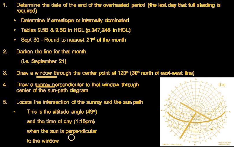
Resources: HCL Table 9.5c Overheated and Underheated Periods


Calculations (Sun Beam Diagrams):


Page | 16
module 5: energy
Review Definitions:
Carbon Neutral: A measure of design that ensures construction and operation of buildings will no longer require the consumption of fossil fuel energy or the emission of greenhouse gases.
Kilowatt kW: is a unit of energy equivalent to one kilowatt (1 kW) of power sustained for one hour.
British Thermal Unit (Btu): a unit used to measure heat. One Btu is about equal to the heat released from burning one kitchen match.
Thermal Mass: material that stores energy, although mass will also retain coolness, The thermal storage capacity of a material is a measure of the material's ability to absorb and store heat.
Thermal mass in passive solar buildings is usually dense material such as brick or concrete masonry, but can also be tile, water, phase change materials, etc.
Indirect Gain: a passive solar system in which the sunlight falls onto thermal mass which is positioned between the glazing and the space to be heated such as a trombe wall.
Passive Solar: design and construction techniques which help a building make use of solar energy by non-mechanical means, as opposed to active solar techniques which use equipment such as roof-top collectors.


Renewable Energy: Power sources that are replenished in a short time. Day after day, the sun shines, the wind blows, and the rivers flow. We use renewable energy sources mainly to make electricity.
Embodied Energy: Power consumed by all of the processes associated with the production of a building, from the mining and processing of natural resources to manufacturing, transport and product delivery.
Benchmarking: Tracking a building’s energy and water use and using a standard metric to compare the building’s performance against past performance and to its peers nationwide.
Non-Renewable Energy: These energy sources are called nonrenewable because their supplies are limited. Petroleum, for example, was formed millions of years ago from the remains of ancient sea plants and animals.
Potential Energy: The power possessed by a body by virtue of its position relative to others, stresses within itself, electric charge, and other factors.
Kinetic Energy: The power that a body possesses when it is brought into motion.
Theories:
Passive Heating Systems

Direct gain
Sunspace
Indirect gain (Trombe walls)
Convective loop (thermosiphon)
Roof pond
Roof radiation Trap
Direct gain clerestory
Direct gain water wall
Page | 17
Controllable passive Isolated gain
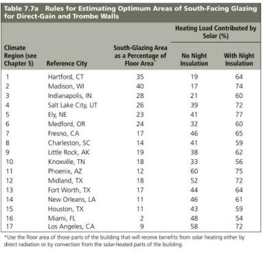
Influences of Direct Gain Orientation Color
Window placement (south facing glazing) Window size & R-value Shading
Passive solar –direct access to solar exposure Potential energy is stored energy and the energy of position gravitational energy. Chemical Stored mechanical Gravitational Nuclear Kinetic energy is motion of waves, electrons, atoms, molecules, substances, and objects. Electrical Radiant Thermal Motion Sound Types of Energy Systems Earth Geothermal Heat pump Biomoass Biofuel Uses kinetic energy Wind Turbines Uses kinetic energy Sun Photovoltaic
Solar thermal Uses kinetic energy Water Hydro-electric Ocean Uses potential energy
Page | 18
Calculations: Heat Loss
Heat Loss by Transmission
Units: Btu (HLT) is a function of:
•Area (A)
•Temperature difference between indoors (Ti) and outdoors (To)
•Thermal resistance of the skin (RT); function of time (ft2 Fo / Btu/h)
Formula: HLT = A x (Ti-To) / RT
***OR: HLT = A x U x (Ti-To)****
Heat Loss by Infiltration
(HLI) is a function of:
•Rate of cold air entering building (ACH)
▪Air Changes per Hour
▪Dependent on Construction & Season
▪Winter (0.5, 0.85 or 1.3 – tight, medium, loose modern construction)
▪Summer 70% of the winter values
•Volume (V)
•Temperature difference between indoors (Ti) and outdoors (To)
•The heat capacity of air is a physical constant and is .018 Btu per (°F) (cu. ft.).
Formula = .018 x ACH x V x (Ti-To)
Transmission Heat Loss+ Infiltration Heat Loss = Total Heat Loss
Heat Gain
Solar Heat Gain through Glazing (HGG solar) is a function of: Glazing Area (A), note: subtract frame area as req’d
Unit Solar Heat Gain Factor (SHGF), ASHRAE Handbook of Fundamentals has charts, need date, time, orientation, latitude
Solar Heat Gain Coefficient (SHGC), need glazing type, shading information, table in HCL Formula = AG x SHGF x SHGC
Solar Heat Gain through Wall / Roof Structure (HGO solar) is a function of:
•Area (A)
•Design-Equivalent Temperature Difference (DETD)
•Total Resistance of the wall / roof structure (RT)
Formula = A x U x DETD
**SAME FOR HEAT LOSS**
Total Heat Gain
Formula = 1.3 x (Total Heat Gain from Transmission + Total Heat Gain from Infiltration + (Total Internal Heat Gain x ft²) + Total Solar Heat Gain (includes thermal mass)
Surface Area = lw+2lh+2hw
Page | 19
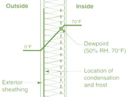
Thermal Gradient


Used to determine if/where the temperature inside the envelope drops below the dew point temperature!

Step 1: Step 2:
Step 3: Step 4: Dew Point:

module 6: wind

Review Definitions:

Photochromics: Materials that can change their transparency in response to light intensity.
Thermochromics: materials that change their transparency in response to temperature
Liquid-crystal glazing: electric charge applied to transparent liquid crystals, making them translucent
Dispersed particle glazing: same as liquid-crystal glazing but can change the transmittance of the material from clear to very dark, excellent for solar control
Electrochromic glazing: most promising material for shading – can change transparency (not translucency) over a wide range

Page | 20
Heat sink: a substance or device that dissipates or absorbs heat, especially unwanted heat
Laminar: Laminar flow tends to occur at lower velocities, below a threshold at which it becomes turbulent.
Turbulent: unsteady vortices appear on many scales and interact with each other. Drag due to boundary layer skin friction increases.
Eddy: swirling of a fluid and the reverse current created when the fluid flows past an obstacle.
Venturi Effect: reduction in fluid pressure that results when a fluid flows through a constricted section (or choke) of a pipe.
Bernoulli Principle: a principle in hydrodynamics: the pressure in a stream of fluid is reduced as the speed of the flow is increased.
Turbine: A water turbine is a rotary machine that converts kinetic energy and potential energy of water into mechanical work.
Theories
1. Cooling with Ventilation
2. Radiant Cooling
3. Evaporative Cooling
Recall sensible heat / latent heat!!!
When water evaporates, it draws sensible heat from surroundings and converts it into latent heat in the form of water vapor
Conversion causes temperature to drop
4. Earth Cooling

Thermal properties of soil
Wet earth is a good conductor and storer of heat.
Beneath it becomes cooler
5. Dehumidification with a Desiccant
Dehumidification Cooling – 2 methods
a. Cool the air below dew point, water condenses out b. Use a desiccant (drying agent) i.e. silica gel, calcium chloride
Passive cooling is much more dependent on climate than passive heating
Shading is the intentional blockage of solar radiation in order to remove the potential for heat absorption into the building.
-Critical in summer when passive solar heating has potential for overheating
-Reduce demand for energy- intensive air conditioning
Wind is the flow of gases on a large scale. Often it is studied as a fluid (fluid dynamics). On the surface of the Earth, wind consists of the bulk movement of air.
Wind is caused by air currents moving from high to low pressure.
Page | 21
Wind is produced due to uneven heating of the atmosphere by the sun, the rotation, and irregularities of the earth.
-Faster moving air > Less pressure
-Slower moving air > More pressure


The Venturi effect is the reduction in fluid pressure that results when a fluid flows through a constricted section of pipe.
The Bernoulli Principle describes that as the speed of a moving fluid increases, the pressure within the fluid decreases.
the faster air moves, the lower its pressure
Airflow Principles


Inertia: Air tends to move in a straight line. When forced, air streams can follow curves but will not move in right angles

Conservation of air: Air is not created or destroyed on site, and Same amount of air that enters site, leaves site
Stack effect: Exhausts air from a building by natural convection only if indoor temperature difference between the two vertical openings is GREATER than those outside, maximize effect by making openings as large and as far apart as possible Air should flow freely (+) Not dependent on wind (-) Weaker than Bernoulli effect

Best when combined with the Venturi effect (shape of the roof) and the Bernoulli effect (increased wind velocity at roof level)
Ventilation
The introduction of controlled wind from outdoor to indoor space is used to decrease energy consumption, and to improve air quality contributing to mold reduction, particulate/voc decrease, and health.
AIR QUALITY + VENTILATION = ach (air changes per hour)
Ventilation Worksheet


Page | 22
Single-Sided
Stack
Solar heat gain warms a column of air, which then rises, pulling new outside air through the building.
Solar Chimney
Application of the stack effect, solar powered Heat the indoor air above the occupied area of the building to increase air flow
Creates negative air pressure that pulls out warm indoor air and pulls in cooler air at lower levels Night Night cooling refers to the operation of natural ventilation at night in order to purge excess heat and cool the envelope.

Window Orientations and Wind Direction


Winds exert maximum pressure when perpendicular to a surface 50% pressure when 45o to surface, but works well because generate greater wind motion indoors
Winds typically vary in direction (wind rose)
Best orientation for building is along E-W axis (solar) If prevailing winds are E-W, still easier to reroute wind than sun

Inlets and Outlets

Inlets and outlets should be the same size
If not possible, make inlet size smaller to maximize velocity of incoming air
Inlet location determines airflow pattern
Page | 23
Cross
Window Locations
module 7: envelope
Review Definitions:
Infiltration: heat loss through joints in the construction, cracks around windows and doors, normal door operation
Transmission: The flow of heat or cold through a building surface.
ACH: ACH is a measure of the air volume added to or removed from a space (normally a room or house) divided by the volume of the space.
Ventilation: Controlled and purposeful form of air exchange.
Summer Heat Gain: similar to heat loss, transmission through walls or windows in winter, except uses summer temperatures, does not take solar radiation into account
Solar Heat Gain: (HGsolar) takes solar radiation into account when calculating skin factors.
Perm: The unit of permeability of a porous material. The mass of water vapor transmitted through a unit area in a unit time under a specified condition of temperature and humidity.
Theories: Envelope ethics
Everything we will go over this week has a foundation from the previous weeks’ worth of passive cooling and heating lessons, CLIMATE lessons, AND the first lesson of R VALUES!!!
-The AIA Research Corporation has identified 17 climate regions (in HCL)
-ASHRAE has also identified several…as you know.
-Each climate region identifies and prioritizes the strategies for greatest conservation of energy, efficiency
Conservation – typically interpreted as a reduction in energy use, a sacrifice, uncomfortable conditions.
Efficiency - thermal comfort can be INCREASED when energy is used efficiently
One of the main ways to achieve this is by tightening the THERMAL ENVELOPE
Four Strategies of Thermal Envelope Design
Winter Defensive – reduce heat loss, reduce temperature swings
Winter Offensive – increase solar heat gain
Summer Defensive – reduce solar heat gain, reduce temperature swings
Summer Offensive – increase cooling strategies, ventilation, evaporative cooling Heat Loss
Three main forms of heat loss from a building
-Transmission
-Infiltration
-Ventilation
Building Shape
Shape – the footprint, the size, the height, the number of floors, the overall configuration of a building; the floor area and surface area
Floor Area – the area inside the thermal envelope
Surface Area – the exterior surfaces that meet the outdoors
Volume – height x width x depth
Page | 24
Thermal Planning of Building Shape
Spaces that require/tolerate cooler temperatures should be located on the north side of a building (bedrooms)
Buffer spaces (garages) should also be on north to block cold wind or on west to protect against heat Occupied spaces in the morning on the east (kitchens, school classrooms)
Area of Building Shape
Reduce Surface Area/Volume Ratio
▪
This idea is correct, but be careful – it assumes the entire envelope (Sa) has the same R-value
▪ Let’s look at examples related to heat loss of walls and roof with different R-values


Recall: HLT = A x U x (Ti-To)
▪ Also referred to as Q = UAΔT, we will use this formula for simplicity
▪ We will consider only transmission heat loss to keep this evaluation as simple as possible…
Calculations for Volume Ratio:

Intents:
Calculations show there are a lot of variables to consider (floor area, surface area, volume, climate, thermal comfort, envelope design, etc.)

In addition, there are also other SIGNIFICANT impacts from building form decisions (shared walls, footprint complexity, ceiling height, roof form, material selection, etc.)
VolumeRatioisjustONEtoolindesign
Note: other factors have a SIGNIFICANT role: Density of occupants (having more efficient ratio or heat loss), consider number of occupants serving
Page | 25
Ratio can affect daylighting, views
Economical trade-offs – i.e. taller buildings require additional structure to resist wind loads, gravity loads, etc.
Sustainable design “tools” at a designer’s disposal – i.e. stack effect, roof area for PVs, etc.
Insulation - Types
1. Batts and Blankets
2. Loose Fill
3. Foamed in Place
4. Boards
5. Air Spaces and Radiant Barriers
Moisture Control
1. Bulk Moisture – liquid water that enters through holes, cracks or gaps; usually rainwater driven by gravity or wind
2. Capillary Action – moves liquid water through porous materials and tiny holes by the surface tension of the water
3. Air Leakage – air carries water vapor through holes and cracks in the building envelope, caused by wind, fans or stack effect
4. Vapor Diffusion – water vapor enters the building envelope driven by a difference in vapor pressure (high to low)
Thermal Gradients
A physical quantity that describes in which direction and at what rate the temperature changes the most rapidly around a particular location.
In architecture, this means the temperatures across a wall, roof, floor are graphed on top of a drawing of the wall, roof, floor, the rate of change of temperature in a given direction A
module 8: lighting
Review Definitions
Luminance = EMITTING light
Illuminance = ARRIVING light
Lumen = amount of ENERGY
Candela = amount of INTENSITY
Daylight Autonomy (symbol DA): Daylight Autonomy (DA) was the first of a string of annual daylight metrics, now commonly referred to as ‘dynamic daylight metrics. It is represented as a percentage of annual daytime hours that a given point in a space is above a specified illumination level.
Ambient Light: general illumination that comes from all directions in a room that has no visible source
The color rendering index (CRI): CRI is an international numbering system from 1 to 100, which is a measure of how well the bulb will render the actual colors of the objects lighted by the lamp.
Sunlight at noon has a CRI of 100, so the higher the CRI the closer it is to natural light. You must use a lamp that has a CRI value of 80 or higher to meet Energy Star requirements.
Light: that portion of the electromagnetic spectrum to which our eyes are visually sensitive
Photometry: measurement of the properties of light (especially luminous intensity)
Page | 26
IESNA: Illuminating Engineering Society of North America, recommended practices and defines light levels and quality of illumination by task and application Task: The work performed
Theories: Solar Studies
Solar Envelope + Solar Access can predict how the sun is acting upon a city, a block, a cluster of buildings, or a building.
Solar access is the site's exposure to the sun during a given period. This exposure enables the utilization of solar properties mainly for radiation, but also for daylighting
The solar path can explain how daylighting and radiation is displaced on the site and building…
Illumination: FC Footcandles Measure of brightness
Heat: BTU or KWh Measure of energy
Daylighting is the accomplishment of illumination of buildings using natural solar optimization. Daylighting is the controlled admission of natural light; direct sunlight and diffuse skylight into a building to reduce electric lighting and saving energy.
Psychological Impacts
Gender, Age, Mood, Cognitive Performance, Spirituality, Emotion Color temperature of lighting affects participants' mood.
Younger + older adults interpreted different emotional meanings from different lighting colors. Participants in a study by Knez and Kers preserved their negative mood better in the cool light than did the younger participants; Younger participants preserved their negative mood better in warm light than did er participants.
Discomfort Glare is the annoyance or pain caused by high luminance’s in a worker's field of view. Instinctive desire to look away from a bright light source or difficulty in seeing a task. The degree of discomfort glare depends on the size, luminance and number and position of glare sources. The most common causes are windows and luminaires. Increasing Application luminance’s decreases discomfort glare.
Veiling Reflection is the reflection of a large luminance area on a task. This results in a loss of contrast between the task and the Application. Veiling reflections are usually caused by windows or luminaires placed above or in front of the task.
The EYE
-Light enters through an opening called the pupil
-The iris muscle allows the pupil to change in size to accommodate varying light levels; process takes 1 hour
-Light is focused on the light-sensitive lining at the back of the eye called the retina. The retina has:
Page | 27
Cone cells that are sensitive to colors
Rod cells that respond to motion and dim lighting conditions
Rapid and extreme changes in brightness can cause stress and fatigue Daylighting typically changes gradually Fovea – small area in the retina consisting mainly of cone cells, surrounding the center of vision; where eye receives most of information re: detail and color; central 2o cone of vision
Foveal surround – about 30o Peripheral - 130o in the vertical, 180o in the horizontal
When seated, center of vision is 15o below horizontal Perception – the brain’s interpretation of what the eyes see Designers must understand that what is designed / built may not be perceived as expected
Illumination Level
As light levels increase to 50 fc, significant increase in visual performance
Above 100 fc, limited gains with additional illumination
General “rule” – keep illumination at 30 fc, increase for task specific lighting Design guidelines for the task, energy efficiency, biology, and aesthetics
Illumination Level & the Quantity of Light…
Guidelines published by Illuminating Engineering Society of North America (IESNA), referred to in ASHRAE
Hawthorne effect – a decrease in illumination levels can cause an increase in productivity
Illuminance (symbol E) : total luminous flux incident on a surface, per unit area. Luminousfluxor luminous power (lm)
Luminance (symbol L): The intensity of light emitted from a surface per unit area in a given direction. The lumen (symbol lm): is the SI unit of luminous flux, a measure of overall light emitted by a light source or human eye. A lumen is a way of measuring how much light gets to what you want to light.
One lumen ≈ 1 FC on 1sf / 1 CP equivalent ≈ 12.57 lumens
The lux (symbol lx) (Lumens per m2): is the SI unit of illuminance and luminous emittance. It is used in photometry as a measure of the intensity, as perceived by the human eye, of light that hits or passes through a surface 1 lux = 0.0929030436 footcandles
Footcandle (symbol FC or lm/ft2): a unit of illuminance on a surface that is everywhere 1 foot from a point source of 1 candle. Non-SI-unit of measurement.
One footcandle ≈ 10.764 lux One lumen ≈ 1 FC on 1sf
Candlepower (symbol CP): Is luminating power expressed in candelas or candles. A candlepower as a unit of measure is not the same as a foot-candle. A candlepower is a measurement of the light at the source, not at the object you light up.
1 CP equivalent ≈ 12.57 lumens
Page | 28


Page | 29
Illuminance and Daylight Factor
glazing area
Calculations: Actual/expected
Required
Light to Solar Gain (LSG) Ratio = VT / SHGC
Ratio of visible light transmittance expressed as dimensionless fraction
→if greater than 1.0 glass transmits more light then heat
→ determines coolness of transmitted
→higher the ratio, the cooler the light
module 9: materials
Textbook Chapters: LEED Materials and Resources Credits
Review Definitions
Embodied Energy: Embodied energy = The available energy that was used in the work of making a product. This lifecycle includes raw material extraction, transport, manufacture, assembly, installation, disassembly, deconstruction and/or decomposition.
Life Cycle Assessment: Life Cycle Assessment= 'LCA', also known as 'life cycle analysis‘ is the evaluation of the environmental impacts of a given product caused by its existence. The goal of LCA is to compare the full range of environmental and social damages assignable to products and services.
Life Cycle Cost Analysis: 'LCCA', is used to evaluate the economic performance of a material or building system over the service life of the material or system. Costs associated with purchasing, installing, maintaining and disposing of an item from the time the item is installed in a building through the duration of the LCC study period are analyzed.
Recycling (Post-consumer waste): Waste material generated by households or by commercial, industrial and institutional facilities in their role as end-users of the product, which can no longer be used for its intended purpose.
Recycling (Pre-consumer waste): Material diverted from the waste stream during the manufacturing process. Excluded is reutilization of materials such as rework, regrind or scrap generated in a process and capable of being reclaimed within the same process that generated it.
EPD: A formal document that communicates transparent information about the lifecycle environmental impact of products.
Page | 30
HPD: Formal document that communicates transparent information of the potential chemicals of concern in products by comparing product ingredients to a wide variety of “hazard” lists published by government authorities and scientific associations.
MATERIALS A
CSI Divisions
CSI is the Construction Specifications Institute. This organization is responsible for categorizing building materials into 15 divisions before 2004, and then subsequently 50 divisions of construction information. The platform is called MASTERFORMAT.

Typically, specs are prepared by the architect or designers.

Materials used in the building include items to be recycled, items which are used in the building, and the health and sustainability of those items as they interact with people
Activities indoors and Climate outdoors are a key feature in determining WHERE the building’s THERMAL COMFORT ZONE will appear on a psychrometric chart!
Page | 31
DETAILS ON LCA
Eutrophication potential (EP) is the collective quantification of nutrients (phosphorus and nitrogen) present in the inland waterways through conversion into phosphorus equivalents.
Acidification Potential (AP) is also known as ACID RAIN. soils and waters are contaminated predominantly through the transformation of air pollutants into acids which have the potential to decrease PH values of rainwater and impact both natural and built environments through degradation.
Global Warming Potential – (GWP) is also known as "Greenhouse Effect/ Carbon Footprint".
The mechanism of the greenhouse effect can be observed on a small scale, as the name suggests, in a greenhouse. These effects are also occurring on a global scale.
Embodied energy is the energy consumed by all of the processes associated with the production of a building, from the mining and processing of natural resources to manufacturing, transport and product delivery.


Embodied Energy vs. Carbon
Embodied Carbon is a better measure of how much ‘goes into’ a material than Energy.
It reflects what really matters, environmentally: the amount of carbon being released into the atmosphere. It’s normally expressed as tons of CO2e that is, of CO2 and its equivalents.
Reducing the amount of energy, it takes to operate a finished building is important.

But the energy embodied in a building can be as much as 50% of the energy used to operate a building in its first 50 years. And as the amount of energy needed to operate

Page | 32
buildings decreases, thanks to improvements in materials and systems, the relative importance of embodied energy will only increase.

Material Health
Materials used in the building include items to be recycled, items which are used in the building, and the impact of those items as they interact with people.
Materials
Natural: Clay, Concrete, Cement, Rock, Mineral, Sand, Wood-based materials
Synthetic: Fabric, Foam, Glass, Metal, Plastic, Adhesive, Paint, Caulking, Adhesives, Coatings the aim of the Cradle to CradleTM Certified Material Health Assessment Methodology is to characterize the hazards of chemicals present in a material and generate material assessment ratings based on those hazards and routes of exposure during manufacturing, application, and end-of-use.
Hazard = the inherent property of a substance having the potential to cause adverse effects when an organism, system or (sub) population is exposed.

Risk = the probability of an adverse effect in an organism, system or (sub) population caused under specified circumstances by exposure to a substance.
LCA may overlook Hazard and Risk
• LCA assess different impacts than intrinsic hazard (carbon, acidification, eutrophication)

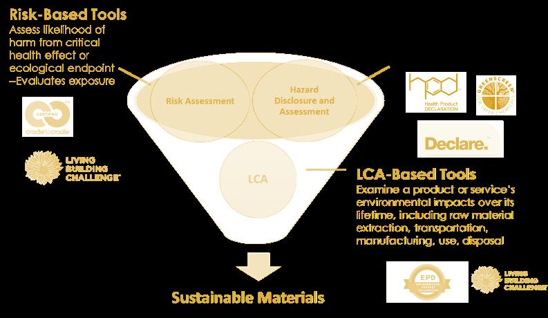
Page | 33
• Toxicity impacts in LCA are not based on inherent hazard, but rather emissions
An EPD® (EnvironmentalProductDeclaration) is a verified and registered document that communicates transparent and comparable information about the life-cycle environmental impact of products.
MATERIALS B
Standard LEED Material Calcs


The Materials and Resources (MR) credit category focuses on minimizing the embodied energy and other impacts associated with the extraction, processing, transport, maintenance, and disposal of building materials. The requirements are designed to support a life-cycle approach that improves performance and promotes resource efficiency.
Each requirement identifies a specific action that fits into the larger context of a life-cycle approach to embodied impact reduction.
CONSTRUCTION WASTE
Establish waste diversion goals for the project by identifying at least five materials (both structural and nonstructural) targeted for diversion. approximate a percentage of the overall project waste that these materials represent.
Specify whether materials will be separated or commingled and Describe the diversion strategies planned for the project. Describe where the materials will be taken and how the recycling facility will process the material.
Provide a final report detailing all major waste streams generated, including disposal and diversion rates
LIFE CYCLE IMPACT REDUCTION
Demonstrate reduced environmental effects during initial project decision-making by reusing existing building resources or demonstrating a reduction in materials use through life-cycle assessment.
CONSTRUCTION WASTE
LIFE CYCLE IMPACT REDUCTION
Page | 34
Achieve one of the following options: historic building reuse

renovation of abandoned or blighted building building and material reuse whole-building life-cycle assessment
Raw material source and extraction reporting
Use different manufacturers that have publicly released a report from their raw material suppliers which include raw material supplier extraction locations, a commitment to long-term ecologically responsible land use, a commitment to reducing environmental harms from extraction and/or manufacturing processes, and a commitment to meeting applicable standards or programs voluntarily that address responsible sourcing criteria.
RAW = the basic substance from which products are made, such as concrete, glass, gypsum, masonry, metals, recycled materials (e.g., plastics and metals), oil (petroleum, polylactic acid), stone, agrifiber, bamboo, and wood
Building product disclosure and optimization – sourcing of raw materials
Bio-based materials. Bio-based products must meet the Sustainable Agriculture Network’s Sustainable Agriculture Standard.
Wood products. Wood products must be certified by the Forest Stewardship Council or USGBCapproved equivalent. Products meeting wood products criteria are valued at 100% of their cost for the purposes of credit achievement calculation.
Materials reuse. Reuse includes salvaged, refurbished, or reused products. Products meeting materials reuse criteria are valued at 100% of their cost for the purposes of credit achievement calculation.

Page | 35
Recycled content. Recycled content is the sum of postconsumer recycled content plus onehalf the preconsumer recycled content, based on cost. Products meeting recycled content criteria are valued at 100% of their cost for the purposes of credit achievement calculation.

USGBC approved program. Other USGBC approved programs meeting leadership extraction criteria.
Material ingredient reporting
Use at least 20 different permanently installed products from at least five different manufacturers that use any of the following programs to demonstrate the chemical inventory of the product to at least 0.1% (1000 ppm).

Manufacturer Inventory.
Health Product Declaration.
Cradle to Cradle.
The end use product has been certified at the Cradle to Cradle v2 Basic level or Cradle to Cradle v3 Bronze level.
USGBC approved program
Diversion
Path 1. divert 50% and three material streams
Divert at least 50% of the total construction and demolition material; diverted materials must include at least three material streams.
Path 2. divert 75% and four material streams
Divert at least 75% of the total construction and demolition material; diverted materials must include at least four material streams.
Option 2. reduction of total waste material
Do not generate more than 2.5 pounds of construction waste per square foot (12.2 kilograms of waste per square meter) of the building's floor area.
Page | 36
module 10: site
Textbook Chapters: HCL Ch. 10
Review Definitions
Monoculture: Agricultural practice of producing or growing a single crop, plant, or livestock species, variety, or breed in a field or farming system at a time. Monoculture farming relies heavily on chemical inputs such as synthetic fertilizers and pesticides.
Low Impact Development LID: Construction techniques to manage and conserve stormwater on site. This method – rapidly being adopted in all regions of this country - is helping communities reduce the impact of the constructed environment on the surrounding natural resources.
Greenfield: Land that has never been developed; virgin land but is being developed my commercial or institutional purposes.
Brownfield: Land that is contaminated with hazardous or chemical ingredients.
Xeriscaping: The conservation of water through creative landscaping which also mimics the natural ecosystem.
Albedo: A measure of the ability of a surface material to reflect light. The scale ranges from 1100 typically.
Stormwater: Water that originates during precipitation events and snow/ice melt and will infiltrate the soil. In instances of hardscape, the water will evaporate, pond, run into the existing ecosystem and / or end up in nearby streams, rivers, or other water bodies.
Bioremediation: Using microorganisms or vegetation to remove contaminants from water and soils. This is a form of in-situ remediation.
Low impact, analysis, and the Strategies of site design
Low-Impact Development strives to minimize the human impact on the ecosystem. It begins with a decision on where to develop and continues up to methods of construction.
Pre-developed – Infill – Urban or otherwise; Renovation, Redevelopment, Brownfield
Construct or renovate a building on a site that is located on a previously developed site within a dense neighborhood with pedestrian access.
Greenfield – Virgin Land
Page | 37
A greenfield site is a virgin site with an ecosystem in tact. Other definitions which include legal greenfield site designations: Prime farmland, Flood Plan land, Endangered species land, Wetland, National Park land
Low Impact Development: Transit
Transport systems have significant impacts on the environment, accounting for between 20% and 25% of world energy consumption and carbon dioxide emissions.
Site should include development in locations shown to have multimodal transportation choices or otherwise reduced motor vehicle use, thereby reducing greenhouse gas emissions, air pollution, and other environmental and public health harms associated with motor vehicle use
Low Impact Development: Stormwater
New York State experienced 1,280 beach closure or advisory days in 2006, many due to the combined sewer overflow systems being overwhelmed by stormwater runoff.
Low Impact Development: Landscape


Conserve existing natural areas and restore damaged areas to provide habitat and promote biodiversity. Employ strategies, materials and landscaping techniques that reduce the heat

Page | 38
absorption of exterior materials. Heat Island | Indigenous / adaptive foliage | Reduce hardscape
Certain methods of landscaping can improve the retention of natural ecosystems in the microclimate while creating a natural infiltration – synergizing with stormwater mitigation, habitat preservation and water conservation.
Low Impact Development: Transit, Stormwater, Landscape
Low-Impact Development strives to minimize the human impact on the ecosystem. It begins with a decision on where to develop and continues up to methods of construction.
Prevent loss of soil during construction by stormwater runoff and/or wind erosion, including protecting topsoil by stockpiling for reuse.
Prevent sedimentation of storm sewers or receiving streams.
Prevent pollution of the air with dust and particulate matter.
Research
Research involves two basic ideas: Questioning the site and compiling the relevant information about the site. These are the basic questions one needs to ask when looking at a site, be it in person or otherwise. We ask ’What is There’?
-Site Survey; Topography, Circulation, Boundaries, Utilities-Site Services, Zoning Setbacks & Regulations, Scaled -Tax Map -Street Map

Page | 39
Synthesis
Selective inclusion Unnecessary Findings (don’t use these), Impactful Findings (use these), Constraints, Opportunities

Data: Photo montage of site, Integration of the critical elements of Research and Documentation.
Conclusions: Diagrams of integration of data (Research and Documentation) in a professional manner.
1-Research – Site Visit
2-Documentation – Climate Consultant + Zoning
3- Analysis
4-Synthesis
Low Impact Development: SITE DESIGN
Prioritize; identify and maximize synergies (i.e., south facing glass – daylighting, passive heating, air quality, ventilation, cooling, acoustics, circulation, vegetation…)
SITE SELECTION: Regarding heating and cooling: building type and climate play MAJOR roles in where best to locate a building on a slope
• Internally dominated buildings can be on north sides of the slopes
• Envelope dominated should be placed according to heating/cooling strategies prioritized by climate region
Page | 40 Documentation
•
Tier 1 – Basic Building / Site Design
• Orientation - Design using solar window analysis, the part of the sky dome through which useful solar energy passes
• Shadow pattern is a composite of all shadows case during winter hours when access is most valuable.
• 9am-3 more than 80% of a winter’s radiation will fall on building.
• Form - The form of the site, including topography, affects wind speed and direction…. …also, solar access, heat gain and shading opportunities, drainage, + acoustics
• SOLAR ACCESS boundary determines how high objects can be before they obstruct the sun. Best when designing single building.
• Vegetation - In areas where wind is desired to foster ventilation, low vegetation, if any, used in airflow path OR use vegetation design to increase air flow. The higher the windbreak, the longer the wind shadow, also dependent on porosity
• Tier 2 – Passive Design Strategies
• Passive Heating & Daylighting
• Passive Cooling module 11: water
Textbook Chapters: GSH Ch. 4 Water & Waste
Review Definitions:
Potable: Water that is drinkable. This type of water requires a high standard of filtration and chemical purification from its source for human consumption.
Stormwater: Water that originates during precipitation and the melting of snow. It infiltrates into the soil or is held on the surface and evaporates or runs off asphalt or hardscape and may end up in nearby streams, rivers, or other water bodies.
Blackwater: Any type of water after kitchen or toilet use. This type of water requires specific filtration processes to achieve a standard of human contact again.
Graywater: Generally clean waste from lavatories, baths, sinks, washing machines and has not come in contact with fecal matter. IT is easy to treat and reuse onsite for toilet flushing, landscape or crop irrigation, and other non-potable uses.
Page | 41
Aquifer: An aquifer is a body of saturated or permeable rock – typically beneath the ground - through which water can easily move. If the amount of water put into the aquifer (recharge) is higher than the amount taken out of the aquifer (discharge), level goes up. If the opposite occurs, water goes down.
Effluent: Treated or untreated wastewater that flows out of a treatment plant, sewer, industrial outfall –commonly referred to as water pollution, it generally refers to waste discharged into surface waters.
Influent: the water that enters the recycling process
Primary: physical process removes some organic matter and suspended solids
Secondary: biological process removes residual organic matter and some suspended solids by microorganisms
Tertiary: physical, biological and/or chemical processes to further remove suspended and dissolved material
Net zero water is like net zero energy; to become self-sufficient as a building. However, without the two parts of passive and renewable.
Through a combination of rainfall harvesting, aggressive conservation, and water recycling, buildings can achieve self-sufficiency from the water “grid.”
Scarcity: Global + Local
1- SURFACE – watershed. - Typically, from surface water sources, such as lakes, rivers, and reservoirs. The watershed is the land area over which water flows into the river, lake, or reservoir.
2- 2- GROUND – aquifers. - In rural areas, people are more likely to drink ground water that was pumped from a well. These wells tap into aquifers the natural reservoirs under the earth's surface that may be only a few miles wide or may span the borders of many states.
Deliberate disposal of waste at point sources such as landfills, septic tanks, injection wells and storm drain wells can have an impact on the quality of ground water in an aquifer.
Pollution: Types + sources
1. DIRECTLY: In developing countries, 70 percent of industrial wastes are dumped untreated into waters, polluting the usable water supply.
2. INDIRECTLY: On average, 99 million pounds (45 million kilograms) of fertilizers and chemicals are used each year.
Consumption: Indoor + Outdoor
Page | 42
There are many types of water. Blackwater, graywater, condensate, rainwater, and potable water. Each has a function in the water cycle, and each one besides POTABLE water may be mitigated to improve the environment and the discharge rate in aquifers or watersheds.
Tiers: Water
As a resource – Tier1
As a passive system component – Tier2

As a generator of electricity – related to Tiers 2 & 3, Tier 2 –includes passive design to avoid use of purchased energy.
Tier 3 includes active designs that use purchased energy, purchased energy can be renewable…
Issues with Water
Unmanaged surface water can have a negative impact on indoor environmental quality Mold –intrusion of water or water vapor; from rainwater, surface water that finds its way into buildings
What designers can do…
Prevent flow of water toward and into the building, provide surfaces that allow water to percolate into the soil rather than flow toward a building -Grade the site away from the building, install foundation drainage system, Install exterior waterproofing system
How do we engage water in design?
OUTDOOR Storm water
Design should protect bodies of water and wetlands, mitigate negative environmental effects of SW runoff, Design should protect inhabitants from negative effects of unwanted water
INDOOR Consume
Building - Human consumption (bathing, drinking, elimination), Fire suppression, Active systems heating and cooling
Consideration of where stormwater goes is critical to limit disruption of natural hydrology. Several ways can be implemented in building design….
Reducing impervious cover,
Increasing on-site infiltration,
Page | 43
Reducing or eliminating pollution from stormwater runoff and eliminating contaminants.
Reuse stormwater for non-potable use.
Design the project site to maintain natural stormwater flows by promoting infiltration.
Specify vegetated roofs, pervious paving, indigenous foliage other measures to minimize impervious surfaces.
HOW?
Keep hot water heated inside thermal envelope
Keep distribution piping inside thermal envelope; insulated or will affect thermal cooling
Minimize distribution piping (point of use); innovative technologies discussed in Enviro 2

Three main ways water contributes to passive design:
Used in passive heating and cooling design (review)
Used in building design passive systems to conserve potable water (conserve supply, not using potable water when don’t need to)
Used in site design passive systems for quality and quantity control (protecting the existing potable water supply – quantity and quality)
Composting Toilets - Two types of composting toilet systems:
•
Self-contained toilets ▪
More labor intensive, utilizing relatively small pans or trays for removal of the humus ▪
Minimal smell, area sealed except when needed
• Centralized units with a destination catchment area
Page | 44
▪
Need only infrequent attention, once or twice a year, regular maintenance
▪
Available in Batch or Continuous Systems
• Batch – uses a compost receptacle that is emptied when container reaches capacity, not yet humus
• Continuous – rely on raking and removal of finished humus
Rainwater Harvesting – the collection of rainwater for potable and non-potable uses, irrigation, laundry, and passive cooling
• Smaller systems collect roof runoff for domestic uses; most frequent for watering the landscape (simple) and toilet flushing (more complex)
• Larger systems use landforms as catchment areas (discussed later re: sites) to increase quality and reduce quantity and can provide supplemental irrigation for agriculture.
Water reuse / recycling strategies depend on an evaluation of the degree of potability the water will need to obtain, i.e. toilet flushing water is non-potable; water for cooking is potable
Greywater – wastewater from lavatories, showers, washing machines that does not include food or human waste
Blackwater – wastewater that contains food and/or human waste
▪
Greywater has less nitrogen and fewer pathogens and degrades faster than blackwater, more economical strategy for recycling / reuse ▪
Recycling / Reusing greywater on site: ▪
Reduces load on sewage / septic system ▪
Lower a building’s contribution to energy use ▪
Create new landscaping opportunities ▪
Depends on how much potable water is used on site that can be recycled & how much demand there is for recycled greywater to be reused or recycled
Ecological Sewage Treatment – an engineered waste treatment system designed to process a building’s sanitary drainage on site by using wetlands; The Living Machine is an example
▪
A series of anaerobic and aerobic tanks house bacteria that consume pathogens, carbon and other nutrients in the wastewater, making it safe to use for reuse/recycling
Page | 45
Hydroponic, most common, relies on bacteria, plants and an overflow wetland

Blackwater reused (recycled) as greywater
Site Catchment Systems
Pervious surfaces – ground covers (softscape or hardscape) that allow rainwater to infiltrate and reach subsurface layers ▪
(+) lessen stormwater runoff ▪
(+) reduce the flow of pollutants from a site ▪
Many systems: ▪
Plastic Grid Systems ▪
Porous (open graded) asphalt pavement ▪
Porous block pavement systems ▪
Porous Portland cement concrete ▪
Bioswales / Biofilters - densely vegetated open channels designed to attenuate and treat stormwater runoff
Swales have gentle slopes at allow runoff to be filtered by vegetation planted on the bottom and sides
Not designed to hold water for an extended period of time
1. Grass Channels - like conventional drainage ditches but with wide flattened sides, providing greater surface area to slow runoff; provides preliminary treatment of water prior to flowing into another stormwater management component
Page | 46
▪
▪
▪
2. Dry Swales - like a detention pond, have water holding capacity and permit water to flow at the bottom of the swale but are designed to have a relatively dry, grassy top; have a fabric wrapped soil base with a perforated pipe to facilitate water movement
3. Wet Swales - essentially long, linear wetlands designed to temporarily store water in a shallow pool; treats water by allowing a slow settling of particles, the infiltration of water and bioremediation of pollutants
Biofilters – like bioswales but in a contained area, box
Retention Ponds - designed to control stormwater runoff on a site and in some cases remove pollutants from the retained water:
Strategies include Ditches, swales, ponds, tanks, vaults- Capture, store, treat and then slowly release stormwater downstream or allow it to infiltrate into the ground
Infiltration Pond – a retention pond that acts as a final storage destination for runoff, water evaporates or infiltrates (no drain)
Detention Pond – a retention pond that is designed to temporarily store the accumulated water before it slowly drains off downstream (has a drain)
Calculations:
Stormwater Reclamation
1. Calculate your daily per capita water consumption for your facility
• How many people will use your building and for how long?
• Are you trying to offset potable water for toilets, lavs and showers? Calculate all of them!
2. Calculate annual water needs by multiplying daily by 365 days per year, or other times/schedules of the operation of the building
3. Determine available rainfall for the building site
• Data available from government source annual summaries http://www.usclimatedata.com/climate/united-states/us
• Assume a dry year (2/3 of average precipitation)
4. Determine required HORIZONTAL catchment area

Page | 47
If you need 50,000 gallons per year and your location provides 30” of rainfall per year (assume a dry year will produce 2/3 of this).
Look at the 20” diagonal line (2/3 of which is 20”) and see where it intersects with the 50,000 gallons catchment yield line – answer is 5,700 sf of HORIZONTAL area.
Or you may do the reverse and find the yield of catchment area in gallons based upon your annual precip and horizontal catchment area.
5. Calculate the cistern capacity
• Assume a storage capacity equal to ¼ annual water needs.* (1/4) x (50,000 gallons)
• In our example: 50,000 gallons per year x .25 = 12,500 gallons
• Assume a storage capacity equal to ¼ annual water.
6. Calculate the volume
• Assess the volume – use the formula
• So using 12,500 gallons
1ft3 = 7.48 gallons - So, our cistern should be 1,671 ft3
7. Design the cistern! Use your creativity (underground won’t freeze as fast in colder climates)
Design a 1,671 ft3 cistern
module 12: synergies
Textbook Chapters: HCL Ch. 19,22 GSH Ch. 5
What is Catholic Social Teaching?
It is a formula or a set of principles for reflection to evaluate the framework of society and to provide criteria for prudential judgment and direction for current policy and action.
The Church's social teaching is a rich treasure of wisdom about building a just society and living lives of holiness amidst the challenges of modern society.

Page | 48
sustainable design encounters the challenge of modern society.
SUSTAINABLE STRATEGY:
A sustainable strategy is one component of a building design which contributes towards a larger goal of reducing the environmental impact on a building; A method, technique, or technology that is used decrease the environmental impact of a building.

-Tilt up Panels, Solar Shading, Geothermal, etc.

SUSTAINABLE SYNERGY:
Multiple sustainable strategies realize as symbiotic components of a sustainable system (if one strategy were to be removed the strength of the design would be compromised).
BUNDLES – SWL Part IV reading
Charrettes are popular with architects, planners, designers and developers as the intensive nature of the process means results are achieved quickly.
SYMBOLS - Examples of universal symbols designating environmental systems. There are many more….

Page | 49
module 13: tools
Textbook Chapters: HCL Ch. 21 Codes + 24 Digital | HCL Ch. 20 IDP + 23 Assessment
In 2012, 60 buildings or projects were zero energy or were Emerging to that level.
In 2018, 482 buildings or projects are zero energy or Emerging to that level.
Energy Codes are not static documents. They are constantly under revision to improve energy efficiency in buildings….new is the ZERO CODE!

ZERO Code is a national / international building energy standard for new building construction that integrates cost-effective energy efficiency standards with on-site and/or off-site renewable energy and results in zero net carbon buildings.

IECC addresses design of energy-efficient building envelopes
3 options to meet: ASHRAE 90.1, Prescriptive set of requirements and Performance Requirements)
EPA Portfolio Manager (PM) Tracks energy and water consumption and greenhouse gas emissions

40% of commercial buildings in the US use this as benchmarking software.
Comcheck/Rescheck helps check compliance with Sustainability Codes.
Page | 50
Performance and Sustainability Trends


Passive Design will receive increasing focus
• The common thread is a renewed focus on passive design principles among them, efficient envelopes, daylighting, and natural ventilation paired with rigorous analytics to identify the most effective strategies and ensure human comfort as well as low energy use.
Firms will push to implement integrative design
BUILDING PERFORMANCE ANALYTICS
BIM sustainability tools used in an iterative process of evaluating the passive impact of various environmental factors on a building’s performance prior to engaging formal energy modeling.

Page | 51
SHADING – BASIC METHOD
DESIGN GUIDELINE METHOD

1. Determine the climate region of building

2. Refer to Table 9.9A or 9.9B to determine angle A (full shade) and Angle B (full sun)
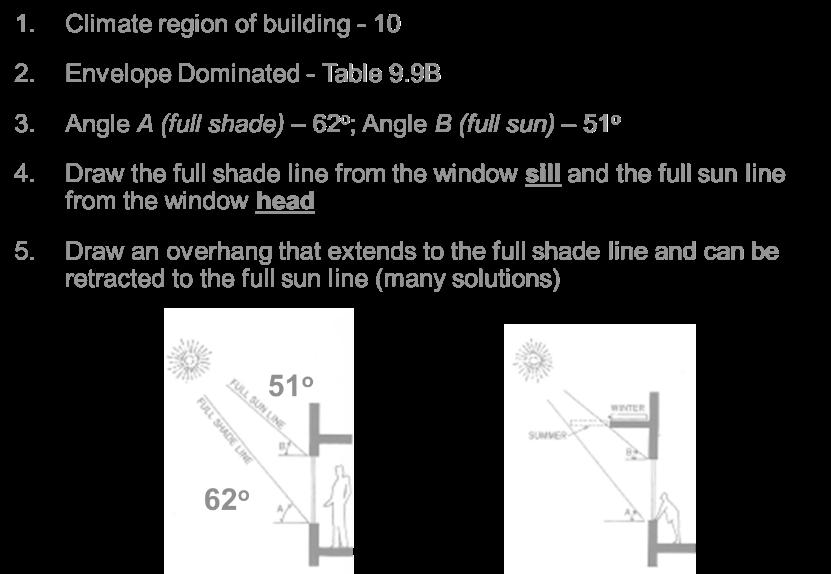
3. Draw the full shade line from the windowsill and the full sun line from the window head

Page | 52
4. Draw an overhang that extends to the full shade line and can be retracted to the full sun line (many solutions)
APPLICATION
Sefaira, IESVE, AUTODESK FORM-IT (SOLAR ANALYSIS), ECOTECT TRANSMISSION HEAT LOSS INFLITRATION HEAT LOSS
TOTAL HEAT LOSS

APPLICATION – FORM- IT (Energy Analysis) THERMAL GRADIENT -


Page | 53
APPLICATION –WUFI® is an acronym for Wärme Und Feuchte Instationär which, translated, means heat and moisture transiency.
RAINWATER HARVESTING

APPLICATION – Sefaira, Sustainable Technologies
PASSIVE COOLING – NATURAL VENTILATION
Autodesk CFD (ventilation contributes to energy reduction), Sefaira (ventilation contributes to energy reduction), Autodesk Form-it (Flow Design), Simulation CFD, WinAir, IESVE – Microflow / Macroflow
DAYLIGHTING

APPLICATION – Sefaira, IESVE, Climate Studio, Ecotect

Page | 54
Using
specificBIMBuildingPerformanceAnalyticalToolsas you design into whole building synergies will help to achieve that goal.
As architects, we have an obligation to integrate ETHICSandMETRICS symbiotically into a holistic sustainable design process.

module 14: assessments
Green assessment systems require an integrated design process to create projects that are environmentally responsible and resource-efficient throughout a building's life-cycle: from siting to design, construction, operation, maintenance, renovation, and demolition.
Green CODE
Green building codes continue to be developed and adopted in the U.S. and abroad that seek to push the standard of building design and construction to new levels of sustainability and performance.
A Prescriptive path is a fast, definitive, and conservative approach to code compliance. Materials and equipment must meet a certain level of stringency, which are quantified in tables.
Performance-based codes are designed to achieve particular results, rather than meeting prescribed requirements for individual building components.
Outcome-based codes for example, establish a target energy use level and provide for measurement and reporting of energy use to assure that the completed building performs at the established level.

What is Assessment?
During a building’s life, there is extensive direct and indirect impact on the environment. During construction, occupancy, renovation, repurposing, and demolition, buildings use energy, water, and raw materials, generate waste, and emit potentially harmful atmospheric e missions.
These facts have prompted the creation of green building standards, certifications, and rating systems (assessments) aimed at mitigating the impact of buildings on the natural environment through sustainable design.
Page | 55
Benefits of Sustainable Design
There are a wide range of economic and environmental benefits to sustainable design, often achieved through the use of standards, rating, and certification systems.
According to a study of LEED certified buildings, the USGBC has found that energy, carbon, water, and waste can be reduced, resulting in savings of 30 to 97% respectively.
Operating costs of green buildings can also be reduced by 8-9% while increasing in value up to 7.5%.
Many sustainable buildings have also seen increases of up to 6.6% on return on investment, 3.5% increases in occupancy, and rent increases of 3%.
Other benefits of green buildings, such as higher productivity and increased occupant health, have been attributed to better indoor environmental quality, increases in natural daylighting, and healthier materials and products within green buildings.
STRATEGY: A sustainable strategy is one component of a building design which contributes towards a larger goal of reducing the environmental impact on a building.
SYNERGY: A synergy is an integration of sustainable strategies which have a positive symbiotic performance to reduce the environmental impact of a building.
-Building Performance Analytics
The process of evaluating the passive impact of various environmental factors on a building’s performance using a sequence of building information modeling (BIM) tools prior to engaging formal energy modeling.
Assessments
WELL measures attributes of buildings that impact occupant health by looking at seven factors, or Concepts. Air, Water, Nourishment, Light, Fitness, Comfort, Mind
Performance Excellence in Electricity Renewal™ (PEER) program. PEER is the nation’s first comprehensive, consumer-centric, data-driven system for evaluating power system performance and is modeled after LEED.
Passive haus is a voluntary standard for energy efficiency in a building, which reduces the building's ecological footprint. It results in ultra-low energy buildings that require little energy for space heating or cooling.
Buildings designed and built to the PHIUS+ 2015 Passive Building Standard consume 86% less energy for heating and 46% less energy for cooling (depending on climate zone and building type) when compared to a code-compliant building.
Page | 56
ENVIRONMENTAL DESIGN II

Page | 57
module 1: synergies
Heating and Cooling Loads
Cooling load = instantaneous heat gain (minus) heat gain that is stored within a building + gains previously stored impacting indoor temp.
(2) A design heat gain (or cooling load) based upon worst-hour conditions used to size cooling systems.
• The orientation
• The tilt of an assembly (vertical, horizontal, inclined)
• The surface reflectance of an assembly
• The thermal capacity of an assembly
• The solar heat gain coefficient of a transparent/translucent assembly
• Shading for any envelope component
• Heat gain (sensible and latent) from occupants
• Heat gain from lighting
• Heat gain (sensible and latent) from equipment
-Calculating Heating Loads is easier than Cooling Loads
Why are cooling loads more high maintenance?
-Occupancy, Equipment, Radiation Radiation, Thermal Lag vary at different parts of the building and inconsistent. -Usually not left to Architects

Why are Heating Loads easier?
Calculating Heat Loss – Night and Winter. (Heat is escaping closer to nighttime Heat Gain calculations help determine cooling required to achieve comfort when it is warmer outside than desired temperature inside.
EXAMPLE:
Heat Rises -
Thermal Bridging – Metal has high thermal bridging. Metal is Conductive. No thermal bridging for wood.
Wood has higher R-value, less conductive so heat passes through it less than it does through metal.
R-5 concrete wall for basement
Concrete has a high thermal mass with properties like brick and stone
Consider – geographic location, material, etc.
Building Construction:
Tight- Envelope is well sealed, less infiltration Medium- Infiltration purposes.
Loose- Allows more infiltration, less use of HVAC and Controlled climate.
Page | 58
Thermal break is defined as a material with low thermal conductivity placed in an extrusion with the purpose of reducing the flow of thermal energy (heat).
Each Façade needs to be treated differently and consider windows, doors, etc.
Total Heat Flow Calculations Include:
▪Conduction: The process by which heat, or electricity is directly transmitted through a material when there is a difference of temperature between two regions without movement of the material.
▪Convection: The transfer of heat by the movement of fluids such as air or water.
▪Radiation: Energy transmitted directly through space which requires a line-of-sight connection between the objects.
HIGH MAINTENANCE COOLING LOAD CALCS!!
Conduction
through walls: Q=UAΔT
All R’s are 12.
Q=Heat (BTU/sq ft)
U=Heat Energy Gain or Loss (how much is going through)
An indicator of how well a window resists conduction. R=Insulating quality of material (how much is being stopped)
Inverse Relationship Area of Fenestration, Walls
Specifically calculating area of the material
ΔT=Change in temperature.
MEEBTableG.2
Design Equivalent Temperature Differential (DETD) DETD is more specific than ΔT, ΔT varies way more than DETD.
Determining ΔT for non-opaque surfaces (fenestration) (ti - to) ti = thermostat setting (indoor) to = design temperature (outdoor)
MEEBAppendixBtableB.1
1. ΔT = (ti - to) = 75 - 83.7 = 8.7

2. determine the DETD design equivalent temperature differences in TABLE G.2 - because we’re interested in walls now, and those have the crazy solar variations of absorption and release!
a. DETD are based on an averageindoortemperatureand outdoor conditions.
Conduction through doors and windows
UfactorsfromMEEBTableE.10
Ufactorsfordoors – TABLEE.10
DCLF=DesignCoolingLoadFactor(MEEBTableG.3)(ifdoorisglazedorforwindows)
ws:
Page | 59
DesignTemperaturesfromMEEBTableF.5(fordoors) andTableF.6(forwindows)
TotalWindowUFactor – TABLEE.15

Conduction through the roof:
1. Area of Roof – Pythagorean Theorem

2. Effective Temperature
Te = effective temperature =to + (α x I/ho) – 7

Te = Sol-air temperature……. te=to+αI/ho – 7oF horizontal surface
Conduction through Basement walls and floor:
ΔT = indoor temp. – design temp.

Design temp: Tdes = average of monthly and yearly average temperature minus amplitude of ground temperature (pg 194)

Page | 60
Toobtaina“designtemperature”forbelowgroundheatloss,
1. Estimate the mean winter temperature of the site location. For example: using Tables C.19 and C.20 in Appendix C,
2. Take the average of the ambient temperature (TA) for January and for the year
3. Then, from this mean winter temperature, subtract the value of the constant amplitude, Fig. 9.10c. This gives a design temperature
4. Table E.13 is then used to determine the heat flow rate.
HeatFlowthroughBasementwallsandfloorfromMEEBTableE.13a+b
Soil provides enough insulation. Conduction through floors:
Notice conduction for basement walls and floor are positive values. Total Heat Conduction
Include all conduction through building envelope
Qcond(total) = ΣUA(Δt)


Qcond = -1286 (walls) – 123.3 (doors) – 9530 (windows) – 4261 (roof) + 3668 (Bwalls) + 1382 (Bfloors) =10150 Btu/hr
Convection
Transfer of heat by moving molecules of a fluid

Two types:
– Natural Convection (Thermal Stack)
• A factor of: Temperature difference

Page | 61
Height difference
– Forced Convection (not heat-related)
• A factor of: Temperature difference
Volume of fluid flow
Heat capacity of the fluid medium
Three categories in this example
– Infiltration Q = ACH x Vol x ΔT x 1.08/60
ACHfromMEEBTableF.3
– Ventilation Q = cfm x 1.08 x ΔT
CFMsreq’sfromMEEBTableF.1&F.2
–
Latent heat gain Q = cfm x 4842 x ΔW

– Thermal Stack Effect
Sometimes use crack method for windows and doors: MEEBTableF.4-partC
Natural Convection is a function of:
–
Volume of transport fluid

– Temperature difference
–
The heat capacity of the transport fluid (=.018 for air)
Source of minimum cfm requirements: (ASHRAE62&MEEBTableF1+F2)
medium refers to construction type.
EstimatedOverallInfiltrationRates – TABLEF.3
Through Envelope MEEBTableF.3
Tight, Medium, Loose
Through doors and windows MEEBTableF.4
Tight, Average, Loose
Next steps:
Volume of Spaces…
Page | 62
Wi and Wo are the indoor and outdoor values of poundsofmoistureperpoundofdryair
More humid outside since the temperature is hotter
Summer thermostat is set at 75oF and RH=50%...
Wi = .0095
Outside is 85oF & 50%RH… Wo = .0129
Conversion Factor of 4842 Total Heat Flow through Convection
Radiation
Thermal radiation is the transfer of thermal energy by electromagnetic waves. It is a direct net transfer of energy by radiation between two surfaces that see only each other.
Qradfen = SHGF(SHGC)(SC)(Area)

Radiant Flux - The time rate of flow of radiant energy and unit is BTU/hr.ft2

On a clear day a horizontal plane receives about 250 BTU/hr.ft2 (Urban)
Cosine Effect - Radiant flux is directly proportional to the cosine of the angle of incidence I = Inormal cos(φ)
SHGC = Solar Heat gain Coefficient found in MEEBTableE.15(E.17skylights)andE.18 a coefficient that represents the percentage of solar radiation incident upon a given window that ends up in a building as heat.

SHGF = the amount of solar radiation through one-layer double strength sheet glass for latitudes listed. Factors Affecting SHGF
• Latitude
• Time of day
• Day/month/season
• Orientation
• Inclination of the surface
• Sky conditions
Page | 63
Qrad(fen) = SHGF x SHGC x SC x area
SHGF = Solar Heat Gain Factor Btu/hr.ft2
SolarHeatGainfactor(Btu/hr-ft2)foundinMEEBTableC.3
SHGC*= Shading Heat Gain Coefficient to account for the difference between the SHGF data and window under considerations
SHGC=SolarHeatgainCoefficientfoundinMEEBTableE.15(E.17skylights)andE.18
SC = Shading Coefficient
*You may use shading coefficient (SC) if you have shading, draperies, etc...
SC=ShadingCoefficientfoundinMEEBTableE.19toE.21
module 2: hvac
Passive & Active Integration
Step 1: Calculating building loads!!!!!!!! Billings, Montana Example
HVAC Active Environmental Systems
Example in MEEB: How does fenestration area prescribed for code compliance compare with desirable fenestration areas for daylight, solar heating, and ventilation cooling?
-Make sure to tab the appendices in MEEB to better organize each table to use.
-Before utilizing active strategies, optimize passive strategies.
ASHRAE 90.1 – Energy Standard for Buildings except low-rise residential buildings
When ignoring passive strategies, there are procedures to demonstrate the importance of well-designed passive systems.
-Window area tradeoffs (more insulation, etc.)
-Methods to compare whole-building annual energy consumption (Energy model) Code:
MEEB Table E.15 Max SC of 0.7
WINDOWS are >_15% of floor area and must have max U value of .36
DAYLIGHT:
For side lighting, DFav = 0.2 (window area/floor area), where all the floor area is within 2.5H of the window wall. If we assume that the ceiling height at the wall is 8 ft (2.4 m) with a window H = 7.5 ft (2.3 m), then the daylight area is 2.5 × 7.5 = 18.75 ft (5.7 m) deep. Light from opposite exterior walls produces the maximum daylight width of 2 × 18.75 = 37 ft (11.3 m). With our assumed maximum 32-ft (9.8-m) width, all floor area is within the daylight zone.
DF= 0.2 (window area/floor area)
DF = 0.2 [0.15 fenestration] = 0.03, or 3% = OK with those factors in table 10.3 MEEB.
PASSIVE SOLAR HEATING: Daylighting Calculations corroborated by SHGC to select window type that best optimize passive heating.
Page | 64
MEEB Table E.15 – Windows & MEEB Table I.1 – Heating season, given solar collecting glazing

If this won’t work, some EEM’s (Energy Efficient Measures) may include:
-Reallocate window area so that essentially all of the glazing faces south (with daylight and crossventilation penalties)
-Allocate more of the south-facing vertical window area to skylights
-Increase the total window area to more than 15% of the floor area, with correspondingly better fenestration U-factors required.
PASSIVE COOLING: Estimate heat gains – MEEB Table G.1
Total operable area of 90% of the glazed area using fully openable casement windows.
With 8% floor area in south windows and 5% in north windows maximum available ventilation area = 0.9 × 5% = 4.5% of the floor area.

From Fig. 12.5, it appears that this rate of heat gain can be removed through this inlet area by a wind velocity of only about 2 mph.
Increase the south glass area (and the overall ratio of window/floor area)
Use windows with lower U-factors, with summer external shading.
The floor and many interior wall surfaces will be faced with thermally massive materials.
This building has now been passively optimized because we have exhausted all of the aspects which can reduce our primary energy consumption. Now we may begin thinking about ACTIVE STRATEGIES WITH THE LOADS WE HAVE CALCULATED.
V THIS IS THE THRESHOLD OF WHERE PASSIVE OPTIMIZATION ENDS AND ACTIVE BEGIN! V
Designing with daylight can improve energy efficiency by minimizing the use of electricity for lighting as well as reducing heating and cooling loads.
Designing using passive heating can improve energy efficiency by minimizing the use of electricity for heating, thus reducing heating loads.
Designing using passive cooling can improve energy efficiency by minimizing the use of electricity for cooling, thus reducing cooling loads.
Page | 65
ACTIVE SYSTEMS “The Other 40%”
In many buildings, due to climate or function, there is a need to supplement passive strategies with active systems. The best strategy is to limit the demand first, then design the systems that will meet it.
Active Climate Control Systems are thermal comfort and indoor air quality modification systems that. -require the use of purchased energy, - involve numerous single-purpose components, -are typically only lightly integrated into the overall building fabric, and -are normally designed by a consultant other than the architect.
HVAC SYSTEMS
active environmental systems address heating and cooling (HVAC) systems, electric lighting fundamentals and design, and water and waste systems.

The interconnectivity of the thermal, luminous, and aqueous environments will vary depending upon the climatic conditions of the site/region, occupancy, function, behavioral activities and attitudes, and the quality of the building materials and enclosure. It is critical that these systems also be optimized to conserve resources.

CODES: Reviewing and Applying to active systems.
ASHRAE dictates that people are comfortable in buildings (thermal comfort)

Standard 62.1 is moving the profession toward provision of code-mandated minimum air quality.
ASHRAE Standard 62.1–2019, Ventilation for Acceptable Indoor Air Quality
ASHRAE Standard 62.2–2019, Ventilation and Acceptable Indoor Air Quality in Low-Rise Residential Buildings recognized standards for ventilation system design and acceptable indoor air quality (IAQ)
Chapter 40 of the 2017 ASHRAEHandbook Fundamentalsprovides an extensive and up-to-date listing of HVAC-applicable codes and standards sorted by subject (ASHRAE 2017).
LEED is an ASSESSMENT SYSTEM
AN ASSESSMENT SYSTEM WILL NOT REFERENCE A CODE CODES REFERENCE ASSESSMENT SYSTEMS
The process of acquiring a viable HVAC system parallels the process of designing a building and generally involves decisions and actions taken during the predesign, design, construction, and occupancy phases of a project.
Page | 66
CRITERIA TO DESIGN HVAC SYSTEMS
Assuming Commissioning process is in place.
-OPR – Owner’s project requirements (design issues, intents, desires, criteria which includes code/standard compliance)
-Establishing zoning requirements
Make Preliminary system selection based on OPR and Zoning.
-Calculate design heating/cooling loads
-Source equipment (in alignment with loads, intent, and context)
Air handling unit
Fans, pumps, valves
-Appropriate distribution approach
Under air flow distribution Ducts
-Coordinate HVAC components with other building systems
“Clash Detection” in Revit – predicts when HVAC runs against other components
-Rough-Size equipment (fans, pumps, valves, dampers, pipes, ducts, condensers, air-handlers, tanks, etc.)
-Run energy analyses to optimize equipment selections and system assemblies. (BPA, etc.)
-Final-size equipment based upon optimization studies. (Usually, won’t figure out during the beginning, still right sizing)
-Coordinate final individual equipment selections into a cohesive whole.
-Develop appropriate control logic and strategies.
COMISSIONING (Cx): more engineering intervention!!!
“A quality-focused process for enhancing the delivery of a project. The process focuses on verifying and documenting that the facility and all of its systems and assemblies are planned, designed, installed, tested, operated, and maintained to meet the Owner’s Project Requirements.”
The commissioning process will verify the likelihood that the HVAC system(s) proposed, designed, and installed will be able to deliver on the performance targets established in the OPR.
13. Develop commissioning test protocols and checklists.
14. Witness systems installation and verifications.
15. Develop systems manuals for the owner.
16. Provide benchmark (new system) performance data for the owner.
17. Assist in initial operations to maintain the owner's project requirements. What is a Commissioning Authority? Systems currently commissioned:
Project Success Advocate

Problem Solver
Generalist not Specialist
Quality Process Focus
Develops Detailed Cx Plan Skilled Communicator
Verifies & Documents
Facilitates Training
Page | 67
Enter the process during schematic design into design development and close to end of installation.
Building commissioning market growth
The American Society for Heating, Refrigerating and Air-Conditioning Engineers (ASHRAE) published the first building commissioning guide, HVAC Commissioning Guide, in 1988, according to the National Conference on Building Commissioning.

Commissioning is NOT…. But it ENCOMPASSES these things NOT: Testing, adjusting, and balancing (TAB) NOT: Contractor’s startup NOT: Engineer’s installation “observation” NOT: Performance verification alone NOT: Limited to HVAC systems or Controls systems
NOT: Routinely included in Professional Design Consultant’s fees NOT: MEP coordination (may assist) DOES NOT: Have responsibility to direct or make corrections to identified deficiencies
Objectives
Owner
Accept an optimized building
Minimized warranty issues
Minimized energy costs
Minimized O&M costs
Maximized functionality Report on construction process
Design Team
Constructed according to design, no less Identify construction issues early Independent perspective on design issues Extra set of observation “eyes”
Contracting Team
Constructed according to design, no more Identify design issues early Independent perspective on construction issues Open the project on schedule & in budget
Minimized warranty issues
Commissioning Economics
Function of Systems’ Complexity & Extent of Services
0.5 to 3% of Total Constructions Cost
1.5 to 4% of Mechanical System Cost
.5 to 3% of Electrical System Cost (Source: Commercial Energy Systems)
Page | 68
Whole Building Commissioning: $0.5 to $1.50 Per Square Foot
Operating Costs: 8 to 20% Below Non-Commissioned Buildings (Source: Kennett, NIBS)
Documentation
Commissioning Team Basis of Design Design Intent Overview of Cx Procedures Pre-Functional Checklists

Functional Performance Testing Scenarios Issues and Resolutions Logs
The National Institute for Building Sciences (NIBS) developed commissioning requirements for the following systems.


Exterior Envelope Roofing Systems
Structural Systems Interior Systems Elevator Systems Plumbing Systems Lighting Systems Electrical Systems Fire Protection Systems
Telecommunication Systems
Lecture 5: Continuation
BUILDING
ENVELOPE COMMISSIONING:
BECx is often associated with building forensics. A 2010 study found that out of 17,000 construction defect claims examined, 69% were due to moisturerelated defects in the building enclosure systems. The scope of building BUILDING ENVELOPE COMMISSIONING can vary widely. For instance, the NIBS (National Institute of Building Sciences) Guideline 3-2006, is “process-oriented to address any
Page | 69
performance objectives required by an owner for the exterior enclosure including the control of heat flow, air flow, noise, fire, light, infrared, ultraviolet, rain penetration, moisture, structural performance, durability, security, reliability, aesthetics, value, constructability, maintainability, and sustainability.”
Envelope Commissioning Components
Exterior Below Grade Walls
Slabs-On-Grade
Exterior Walls
Exterior Glazed Windows, Curtainwalls and Storefronts
Exterior Doors
Sealants, Control Joints & Flashings
Shading Devices
Roofs / Garden Roofs
Skylights / Sloped Glazing
Infiltration Testing - Commonly referred to as a blower door test, infiltration testing quantifies the tightness of a building’s envelope so that cost savings can be realized through renovation or by avoiding the cost of a renovation that will not have the desired effect of reducing utility bills.

Blower Door Test – incase necessary
New York State code adds some interesting notes in their supplement to the IECC 2015 for the blower door test and how it is conducted, which clarify how the NYS code wants you to interpret ASTM E779/E1827:
Exterior doors/windows closed, but not further sealed
Dampers of exhaust, intake, make-up air, backdraft, and flue dampers shall be closed, but not sealed beyond intended infiltration control measures
Interior doors shall be open, if installed at the time of the test
Exterior openings for the continuous ventilation system and heat recovery ventilators shall be closed and sealed (which makes sense as it is included in the energy model, and doesn't result in additional leakage)
Heating and cooling systems, if installed at the time of the test, shall be turned off
Supply and return registers, if installed at the time of the test, shall be fully open
Testing can only be done after all penetrations of the building thermal envelope have been made
The code official can require an approved 3rd party to the test and a written report in NYS. It is not completely clear what an approved 3rd party is, but a PE or RA would certainly make the cut. The code official might consider BPI/RESNETrater or Certified Passive House Consultant/Designer as an equal too, but that is not explicitly stated.
The report adds a few interesting additional requirements:
Page | 70
Atria
• Floor area per ANSI Z65 (pretty much enclosed floor area from exterior of the wall) + areas less than 5' in height. However, it doesn't provide guidance regarding ceiling heights or calculating volume, albeit that should be self-explanatory.
• NYS requests that the blower door test is of the air volume lost at internal pressurization of 0.2 inches w.g. (50Pa). We take this to imply that the test is done with pressurizing the building. This would be rather odd as most blower door tests only depressurize the building and we expect this not be interpreted this way by the Authorities Having Jurisdiction (AHJ).
THERMODYNAMICS
Reviewing and applying to active systems
A few laws which are beyond or before codes...
Zeroth law: Two systems that are in thermal equilibrium with a third system are in thermal equilibrium with each other. This law helps to define the notion of temperature. Heat will only flow from a higher to a lower temperature. If two objects are at the same temperature, there will be NO HEAT FLOW between them. This marks temperatureas the indicator of thermal equilibrium.
First law: Heat and work are forms of energy transfer. Energy is always conserved; thus, all energy associated with a system must be accounted for. Perpetual motion is impossible, and efficiencies greater than 100% are impossible. All macro energy forms within a building devolve to heat. ENERGY CAN’T BE CREATED OR DESTROYED. ONLY CONVERTED!
Second law: A system attempts to move toward a state of thermodynamic equilibrium, which increases entropy (disorder). It takes energy to order (and maintain order within) a system, which will otherwise naturally move toward disorder.


Third law: The entropy of a system approaches a constant value as the temperature approaches zero; this is not particularly germane to HVAC system design.
AN OBJECT WILL ALWAYS GATHER HEAT FROM ITS ENVIRONMENT. If we can’t get absolute zero, nothing in the universe will be absolutely still.

As the temperature decreases, THEN kinetic energy decreases = absolute zero.
PSYCHROMETRICS
Reviewing and applying to active systems
Psychrometrics is the study and manipulation of the properties of moist air.

Page | 71
Adjusting the properties of air = what the thermal side of an air-conditioning system is intended to do. HVAC systems are psychrometric systems. A FUNDAMENTAL understanding of moist air properties andtheirmodificationis critical to an understanding of climate control systems. Again (ad nauseum! Sorry ) the psychrometric chart, is a means of understanding the relationships among various properties of air. The psychrometric chart in the case of active systems, namely HVAC, is used as a design tool.

a. HUMIDITY RATIO
the amountofmoistureby weight within a given weight of dry air. Values of pounds of moisture per pound of dry air.
b. SPECIFIC VOLUME


the densityofairvaries as its temperature and moisture content vary.
c ENTHALPY
the sumofthesensibleandlatentheatcontentof an air-moisture mixture relative to the sum of the sensible and latent heat in air at 0°F (0°C in SI units) at standard atmospheric pressure.
1. Sensible Heating
Room air temperature is increased with no change in absolute humidity. Relative humidity will decrease as the air is heated, but there is no change in air moisture content. Hot air heating, baseboard radiation, and solar heating systems are all sensible heating systems.

2. Heating + Humidifying

Page | 72
This process, which moves up and to the right on the psychrometric chart, is often desired in smaller buildings located in cold climates. There is no single HVAC device that will produce this effect; sensible heating equipment must be paired with a humidification device.
3. Heating + Dehumidification
This process adds moisture to the air without intentionally changing air temperature. A device called a humidifier can accomplish this effect (although rarely will this alone be adequate to produce thermally comfortable conditions).
4. Humidifying
This process adds moisture to the air without intentionally changing air temperature. A device called a humidifier can accomplish this effect (although rarely will this alone be adequate to produce thermally comfortable conditions).
5. Dehumidifying
This process removes moisture from the air without intentionally changing air temperature. A device called a dehumidifier can accomplish this effect. This may occasionally (in benign climates) be the only effect required to produce thermally comfortable conditions.
6. Sensible Cooling
This process reduces air temperature without a change in absolute humidity. Some HVAC systems will produce sensible cooling through a part of their operating range. Other HVAC systems (such as a radiant cooling system) are specifically designed to operate as sensible cooling devices. Most active cooling systems, however, produce sensible and latent cooling effects.
7. Cooling + Dehumidification

This combined sensible and latent cooling process is commonly desired in a wide range of building situations and is produced by the common vapor compression cooling process. A cooling coil is brought to a temperature below the dew point of the room air such that moisture condenses and leaves the air while the air is reduced in dry-bulb temperature.

8. Evaporative Cooling


This process, which involves simultaneous sensible cooling and latent heating (cooling and humidification), an HVAC option. Where climate conditions will support this process, direct evaporative cooling can be a very energy-efficient space-cooling option.
Indirect evaporative cooling can be employed where high relative humidity resulting from a direct evaporative cooling process would be objectionable.


Page | 73
the sumofthesensibleandlatentheatcontentof an air-moisture mixture relative to the sum of the sensible and latent heat in air at 0°F at standard atmospheric pressure.
Example 14.1
HVAC Anatomy Metrics


The new language of HVAC
In many cases there will be a mandated minimum performance threshold that is embedded in a building code. The minimum acceptable performance values for most common types of source equipment will be found in ASHRAE Standard 90.1.
HVAC Ductwork Symbols
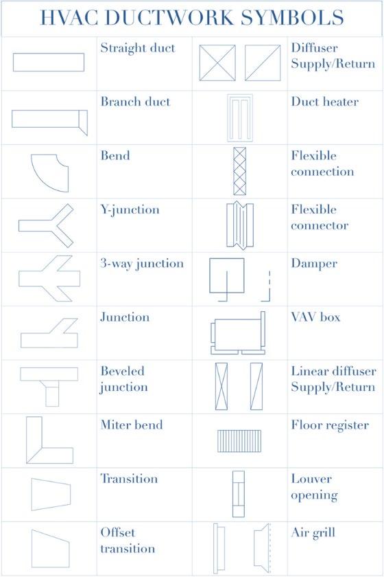
Annual fuel utilization efficiency (AFUE)
Efficiency
the ratio of system output to system input when both values are presented in consistent units; it is expressed as a decimal value or percentage. It should be taken to mean instantaneous efficiency at some defined point in time and under some specific set of operating conditions.

Page | 74
is the ratio of annual fuel output energy to annual input energy, which includes any off-season pilot input loss.

AFUE Rating = Output Energy / Input Energy (based on 100% efficiency)


*OUTPUT ENERGY SHOULD BE ON PAR WITH INPUT ENERGY
Coefficient of performance (COP)
For cooling, it is the ratio of the rate of heat removal to the rate of energy input in consistent units, for a complete cooling system (or factory-assembled equipment), as tested under a nationally recognized standard or designated operating conditions.

For heating (heat pump), it is the ratio of the rate of heat delivered to the rate of energy input in consistent units, for a complete heat pump system as tested under designated operating conditions. Supplemental heat is not included in this definition.
Seasonal coefficient of performance for cooling or for heating (SCOPC, SCOPH) is the formulation
Page | 75
of COP that considers the total output of a device during its normal operating season (versus an instantaneous output value for COP).

Energy efficiency ratio (EER) is the ratio of net equipment cooling capacity in Btu/h to the total rate of electric input in watts under designated operating conditions. (When consistent units are used, this ratio is the same as COP.)

Seasonal energy efficiency ratio (SEER) is the total cooling output of an air conditioner during its normal annual usage period for cooling, in Btu, divided by the total electric energy input during the same period, in watt-hours. This rating of a unit looks at an air conditioner a bit more granularly calculating the cooling capacity during a typical cooling-season (rather than all-time)

Integrated part load value (IPLV) is a single-number figure of merit based on part-load EER or COP expressing part-load efficiency for air-conditioning and heat pump equipment based on weighted operation at various load capacities for the equipment.
Heating seasonal performance factor (HSPF) is the total heating output of a heat pump during its normal annual usage period for heating, in Btu, divided by the total electric energy input during the same period, in watt-hours
Energy utilization index (EUI), also energy use intensity, is an indicator of total annual building energy usage normalized per unit floor area; Btu/ft2 yr (W/m2 yr); for a typical building, HVAC energy is a large part of EUI. Therefore, we want to PASSIVELY OPTIMIZE and REDUCE DEMAND before using active systems.

Page | 76
Components
MEEB 14.6

Sourcecomponents. These produce heating effect and/or cooling effect. E.g (Cooling Tower, Boiler, Refrigerant Cycle)
Distributioncomponents These circulate the heating/cooling effects from the source(s) to the various conditioned zones (in a local system this component category is minor or nonexistent). E.g (Air Handling Unit, Ductwork, Fans)


Deliverycomponents These introduce the heating/cooling effect into the various spaces being conditioned. E.g. (Diffuser, Baseboard, Chilled Beam)
Controlcomponents. These provide for beneficial operation of a system, such as on-off functionality, temperature control, energy efficiency, freeze protection, fire response, etc.

Page | 77
Heat Source Components
MEEB 14.5 + 6
Heat is generated for a space by fast molecules.

On-site combustion: A fuel of some type (natural gas, oil, propane, firewood, coal) is burned on site, usually within the building; heat is produced as an outcome of the combustion process. The fuel may be delivered to the building site upon demand (natural gas) or be delivered in bulk for onsite storage (fuel oil).
Combustion air will need to be provided at the combustion location and combustion gases exhausted from the building. Except for biomass, heating fuels are nonrenewable and all produce carbon emissions. *

Electric resistance: Electricity is passed through an electrical resistance element to produce heat; the electricity may come from an off-site (via a utility) or on-site source (such as PV or wind).
The name is a misnomer. The name implies that if I increase the resistance to current flow that I will increase the heat that an element produces – but it’s the opposite! We will learn more about electricity in our next module.
Heat transfer: Finding heat already on site and moving this heat to a place where it is more useful is the essence of heat transfer. Heat transfer does not require the introduction of “new” energy and can be very energy effective; Heat pumps and air-to-air heat exchangers are both commonly found in highperformance buildings.
Page | 78
SOURCE:
1. Boilers – MEEB 14.6A
Energy capture: This approach is like heat transfer, but an energy form other than heat is tapped into and converted to heat for use in a building. These tend to be carbon-free and economically free such as solar heating.

Boilers produce hot water or steam; the heat source may be electric resistance or on-site combustion.
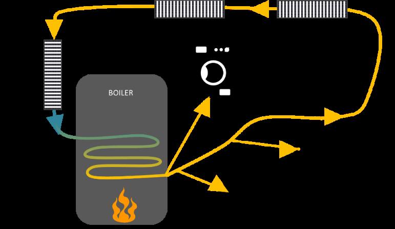
-Commercial, Residential, or Institutional.
Hot Water makes steam
2. Furnaces
– MEEB 14.6C
A furnace produces hot air that can be distributed to spaces via a central ductwork system, OR without one. The heat source for a furnace is most commonly on-site combustion (using natural gas, propane, or fuel oil) or electric resistance.
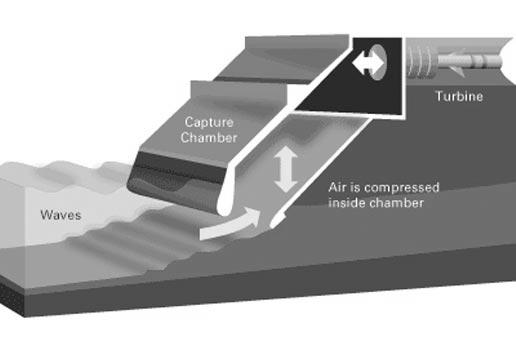


The pellets are made from densified quality sawdust, a manufacturing by-product. The form and content of this fuel produce a highly efficient burn with less pollution emitted. The fuel is cleaner and takes less storage space than cordwood.
3. Wood Burning – MEEB 14.6D
With each improvement from campfire to fireplace to wood stove, more of the heat from the fuel was captured for use rather than wasted to the outdoors
Page | 79
(Fig. 14.21).
4. Infrared – MEEB 14.6E
Infrared heaters are often seen in semi-outdoor locations such as loading docks, repair shops, and higher-end bus shelters. They are fired with either natural gas or propane or powered by electricity.
Coolth
Vapor compression refrigeration: The vapor compression cycle is a mechanical-electrical circuit in which a refrigerant is circulated under temperature conditions that allow it to pick up heat from within a building and dump heat to the outside environment

Vapor compression is by far the most used and encountered means of producing a cooling effect for an HVAC system. All vapor compression systems require an externally placed heat rejection unit (a condenser).
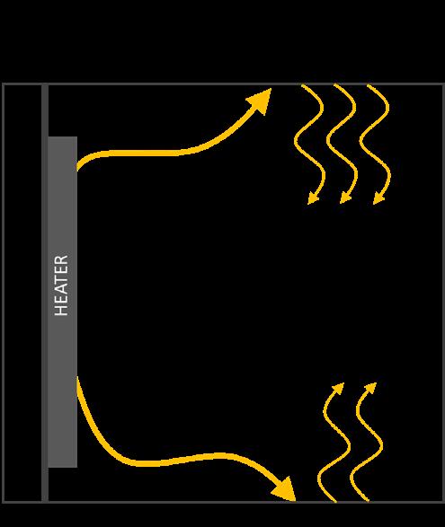
Absorption refrigeration: The absorption refrigeration cycle is diagrammatically like the vapor compression cycle but employs a chemical refrigerant flow process driven by heat to pick up heat from within a building and dump heat to the outside environment

Absorption refrigeration equipment is less efficient (has a lower COP) than comparable vapor compression equipment, but may be driven by waste heat, solar hot water, or natural gas.

Page | 80
Evaporative cooling:
In an HVAC system, an evaporative cooling effect will be produced by equipment called an evaporative cooler

This approach to coolth production can be very energy efficient (operating as it does along a line of approximately constant enthalpy); COP values can reach 15–20.


With variations in equipment type, evaporative cooling can be used to directly cool air or to cool water.
Coolth – Source Components
COP – Coefficient of performance
COP is a measure of the efficiency of a refrigeration process
Determined by dividing the cooling effect by the power used to accomplish the process
For heating: Heating COP
For Cooling: EER (unitary) or SEER (seasonal)
EER
If a cooling system uses 1kW to produce 1 ton of refrigeration, what is its COP (EER)?

1ton = 12000 BTU/hr
1kW = 1000 X 3.412BTU/hr
EER = 12000/3412 = 3.5
Page | 81
• Absorption Cycle 0.5-1.0 COP
• Compression 2.5-7 COP
• Air-source Heat Pump EER = 13-20
• Ground Water HP EER = 13 or more
Cooling – Production Equipment

Two options
Direct Expansion Systems (DX)
Chilled Water Systems
Heat is removed from a building via the chilled water and rejected from the building via the condenser water thus cooling the building.
The cycle operates by cyclical liquefaction and evaporation of a refrigerant, during which processes the refrigerant releases and absorbs heat, respectively.


1. Vapor Compression Fridge (MEEB 14.8)
Hydrochlorofluorocarbon (HCFC) refrigerants are an interim replacement for CFCs they are still a threat to the atmosphere, but not as great as CFCs.

Page | 82 COP
Direct expansion refrigeration: The preceding discussion of vapor compression refrigeration cycles tended to focus on chillers which provide cooling effect through the medium of chilled water circulated to loads located within a building.

• A direct expansion (DX) refrigeration cycle provides cooling effect through the action of room air passing across a coil that contains circulating refrigerant. A DX system is simpler than a chiller system, but has application limitations.

Variable refrigerant flow (VRF): In a VRF system, one compressor/condenser unit can be connected to multiple evaporators. Each evaporator unit can be individually controlled (each is a thermal zone). This arrangement is similar to that found in ductless mini-split systems (Fig. 14.32), where one outdoor unit can be used with several evaporator units.
2. ABSORPTION COMPRESSION REFRIGERATION
This process uses water as the primary refrigerant and lithium bromide (a salt solution) as the absorber. Heat drives this chemical process.

Absorption refrigeration is less efficient (has a lower COP) than the vapor compression refrigeration cycle and requires about twice the heat rejection capacity.
3. AIR-COOLED CONDENSERS
Air-cooled condenser - by which heat removed from a building is dumped to the outdoor environment.
Page | 83
These types of condensers pass refrigerant gas through a coil over which outdoor air flows. The temperature of the refrigerant is higher than that of the outdoor air so that heat flows from the refrigerant to the air.

Air-cooled systems
Require 600-900 cfm per ton of refrigeration
The higher the outdoor temperature, the lower the system efficiency
High operation cost
Low initial cost
No water freezing problem
No water treatment required
No condensing water pump required
4. WATER-COOLED CONDENSERS
Water is used to extract heat rejected from the condenser
Sources of water:
Domestic water
Ponds
Wells and rivers
Cooling Towers
Chillers often employ a water-cooled condenser connected to a cooling tower to reject the heat that is removed from the chilled water system.
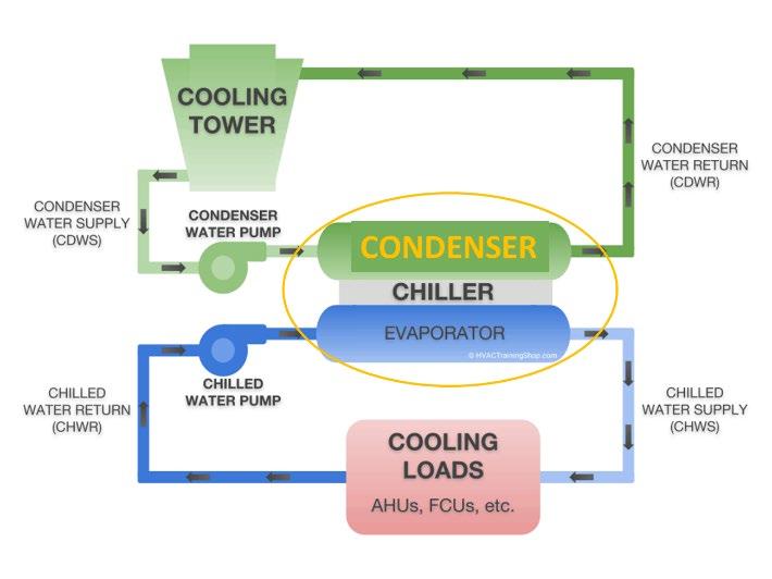
A cooling tower is a specialized heat exchanger in which air and water are brought into direct contact with each other to reduce the water's temperature.


Page | 84
Cooling towers create a special and unpleasant microclimate. They move huge quantities of outdoor air which they make considerably more humid.

Free air circulation
Avoidance of any obstructions near inlets
Discharge should be unimpeded

1-1.5 times the height of the tower
Careful placement of discharge outlet to avoid humid, moist, and polluted air from affecting interior systems or other HVAC air intake

5. HEAT PUMPS


A heat pump uses the refrigeration cycle to both heat and cool; in an HVAC system it is thus both a heat source component and a coolth source component. The
A cooling-only cycle is called a refrigeration system. A bi-directional (heating and cooling) cycle is called a heat pump.


Page | 85
package unit (a) and the outdoor unit of the split system (b) are also typically placed either on the ground or on a roof
Geothermal energy produces electricity by deep wells and pumping the heated underground water or steam to the surface

It is KINETIC ENERGY because of its thermal process…the vibration and movement of the atoms and molecules within substances.
Ground Source Heat Pumps on the other hand use stable temperatures near the surface of the earth to heat and cool buildings.
One of the primary attractions of a heat pump is that in the heating mode it can deliver more energy than it consumes. draws “free” heat from a source such as outdoor air.
The total heat delivered to the building is substantially more than the heat equivalent of the electricity required to run the cycle.
6. EVAPORATIVE COOLING
This approach to cooling involves a basic psychrometric process. Evaporative cooling may, in fact, be achieved through passive means, via a

hybrid system (mostly passive with a bit of help from active components), or by means of an active system. Active evaporative cooling employs equipment called an evaporative cooler.

DISTRIBUTION
COMPONENTS of air and water (MEEB 14.9 + 14.10)
Distribution components These circulate the heating/cooling effects from the source(s) to the various conditioned zones (in a local system this component category is minor or nonexistent).

Distribution components connect source components to delivery components in a central HVAC system.

Local systems are close-coupled and have little need for distribution; district systems function as central systems at the building scale.
The building designer faces a fundamental decision regarding the medium that will be used to convey heat and/or coolth effect around a building. Should this medium be air or water?

Page | 86
Both will work, both have been used effectively in the past, and both are competing for attention in highperformance buildings.
Air can be directly introduced into a room, can inherently address indoor air quality concerns, but has very low thermal capacity requiring large conduits (ducts).
Water is thermally efficient permitting small conduits (pipes) but cannot be allowed to flow directly into a room and does not inherently deal with air quality.
When water is employed as a distribution medium in a central or district HVAC system, duct sizes will be substantially reduced (in air–water systems) or ductwork will be eliminated (in all-water systems).
This outcome is a result of the much, much higher thermal capacity of water versus air.

(a) Pumps
Pumps are used to circulate water through the various piping networks associated with building HVAC systems (including chilled water, heating water, and condenser water systems). Centrifugal pumps are commonly used in HVAC systems.

Pump performance hinges upon flow rate and head (pressure to be overcome); pump curves allow analysis of pump performance in the context of building performance (including operation at partial loads). Reducing pumping power draw and energy consumption are goals for a high-performance building.
(b) Piping


Steel pipe and copper tubing are the default materials for HVAC piping systems. Pipe segments will be connected using any of several methods suitable for the pipe type and application. Fittings will be used as required to change direction, transition pipe sizes, and connect to equipment. Pipes will be insulated when heat loss or gain will affect system performance and energy efficiency. ASHRAE Standard 90.1 provides requirements for thermal insulation. Chapter 46 of the 2016 ASHRAE Handbook HVAC Systems and Equipment provides detailed information on pipes and fittings.
Accessories. Piping system accessories include valves, temperature sensors, pressure sensors, strainers, test ports, and the like.
Valves are an integral aspect of water distribution. They may provide manual on-off control for isolating equipment during maintenance, or they may operate under automatic control to meet the control sequences established by the HVAC designer
(c) Steam
Vaporized water is produced by a boiler and distributed to loads via a piping system. At the loads, steam is condensed, and the condensate (water) returned to the boiler. Steam traps are installed to ensure that only condensate returns to the boiler.
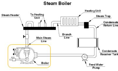

Page | 87
Air can be directly introduced into a room, can inherently address indoor air quality concerns, but has very low thermal capacity requiring large conduits (ducts).
This outcome is a result of the much, much Lower thermal capacity of air versus water.
(a) Fans
Ceiling fans are useful for both heating and cooling. In winter, at slow speeds, they destratify warm air at the ceiling. In summer they extend the comfort zone by providing increased air motion. Ceiling fans are often installed to run at slow speed to destratify warm air at the ceiling in winter.
They can be run at higher speed in summer to provide added comfort through increased air motion. The air motion produced by ceiling fans will vary with the fan height above the floor, the number of fans in a space, and the fan power, speed, and blade size.
(b) Air Handling Units (AHU)
An air-handling unit (AHU) is a packaged component that is found in both all-air and air-water HVAC systems.
Depending upon project needs, an air-handling unit will normally include a fan (to circulate air through the system), a filter (to clean the air and protect the fan and coils), a cooling coil (when cooling is required) and/or a heating coil in some system types.


Duct System
Distributes hot/cold air into and/or out of conditioned spaces


IMPORTANT CRITERIA
• Pressure loss:
• Insulation:
• Noise control:
• Fire protection:
• IAQ
• Approximate sizing:
• Determine the quantity of air to be distributed through the duct element of interest.
Page | 88
• Express the airflow in cfm (L/s).
• Establish a maximum velocity Table 14.4
• Part of the air handling system.
• Only supply and return ducts connect AHU’s to conditioned spaces.
• Intake and Exhaust ducts connect from AHU to exterior.
Duct Types
By Shape: Rectangular
For low-velocity applications - Insulation is usually applied to the interior (duct liner)
Duct insulation serves the thermal purposes in addition to sound attenuation benefits
Round
May be used for low-speed applications
Suited for medium to high-speed ductwork
Often use external insulation (fiber glass wrap) and external vapor barrier for cool applications
Very common in HVAC systems
Advantages:
Strong, rigid, efficient, and economical
Highest ratio of cross-sectional area to perimeter (efficient)
Lowest static pressure friction loss
Cheaper (higher value) and lighter than rectangular ducts for same cfm capacity (uses less materials to obtain same cross-section)
Rigidity minimizes noise and vibration transmission
Disadvantages:
Round shape may not fit into often rectangular-shaped construction (under ceilings etc.…)
Oval
Advantages:
Medium to high-speed applications
Solve some of the bulk problems of round ducts
Almost as efficient and rigid as round ducts
Being flat allows them to be located in tight areas
Disadvantages:
Costly
Flexible Ducts
Two types:
Metallic (insulated and bare)
Metallic Helix (spiral)
Used in short runs (high pressure friction loss).
Used in low velocity systems
More expensive than rectangular, but less costly than customized fittings for rigid ducts
Page | 89
By Material:
Galvanized steel
Most widely used for supply and return
Painting and weatherproofing are recommended when used outside (zinc)
Advantages: Strong Rust resisting Non-porous Durable
Easily cut, drilled, welded, and painted
Disadvantages: Weight (heavy)
Highly conductive (require insulation) High noise transmission
Noise from vibration, however thermal insulation layer will dampen the noise from vibration only Aluminum
Often substitutes galvanized steel ducts
Advantages: Light and weather and corrosion resistant Can be used exposed in the interior spaces
Disadvantages: Cost Low strength
High thermal expansion coefficient (long duct e.g., commercial applications)
Thermally conductive Fiber glass

Rigid Fibrous Glass Boards: One-inch-thick boards
Made of fibrous glass and aluminum (plane or reinforced) facing Aluminum facing act as a vapor barrier and aesthetics
Advantages: Light weight Good thermal characteristics
Good acoustic qualities Simple to fabricate and install
Disadvantages: Cost
Sensitive to moisture and other environmental degradation
Low strength
Not acceptable by some codes
Duct Fittings and Air Control Devices Design Criteria
Page | 90
Inflated Membrane Ducts
• Decrease Static Friction Loss


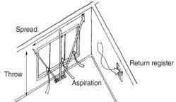
• Reduce turbulence (more laminar flow)

Achieved by
• Reducing lengths
• Simplifying runs
• Choosing smooth surfaces
• Designing for smooth and gradual transitions
DELIVERY
COMPONENTS of HVAC sources after distribution (MEEB 14.11)
Air Delivery Outlets
• Grilles have slits that allow air to flow through the cover
• Registers are like grilles with one addition, a damper The damper is a mechanism on the back that allows you to open and close the register to control how much air can flow through the hole.
• Grille:is any slotted, louvered, or perforated cover that fits into a duct termination. The louvered grilles have (movable/fixed) horizontal and/or vertical vanes. They can be mounted on walls and ceilings
• Register:is a grille that is equipped with a volume damper for control of airflow. Used in most cases in supply ducts
• Diffuser:is a supply air outlet that distributes air in a widespread pattern roughly parallel to the surface in which it is mounted. Mostly used in ceilings and may or may not be equipped with volume dampers
Outlet Performance
An increased distance could allow colder supply air to be distributed, resulting in smaller ducts, and could also allow higher velocity of supply


Page | 91
air, further reducing duct size.
-HVAC Ductwork 2D Symbols for Reflected Ceiling Plans
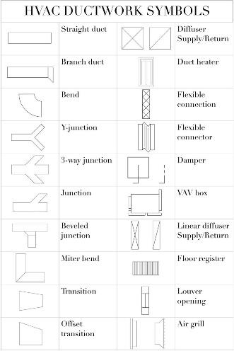
AlternativeAirDeliverySystem:
-Air-extract window, an air curtain window, or a climate window.

-A triple-glazed window that passes room air between a typical outer double-glazed window and an inner single pane.
-The inner pane thus is kept at very nearly the same temperature as the room air, which greatly increases comfort (via the mean radiant temperature [MRT] effect) near windows on very cold (or very hot) days. Blinds are often inserted within!
Water Delivery Outlets
Delivering water to spaces conditioned by an air–water or all-water HVAC system is a much more difficult proposition than delivering air -Water CANNOT be directly introduced to a space – DELIVERING THE AIR from the hot water

Air that encounters the finned tube (a mini coil) is heated by indirect contact with hot water, rises by convection, and distributes heat to the space. Air circulation is natural, and no filtering of circulated air occurs.

Hydronicbaseboardheaters:
Baseboard radiators located under windows (as a means of offsetting heat loss and increasing glass surface temperature to improve MRT and resist condensation). These units are heating-only devices.
ValenceUnits:Valance heating and cooling units are like radiator units, only these units also cool spaces and are located on the ceiling for more freedom of space planning. They are not very popular.

Convectors:They can provide a high-output heat source due to their fins. These are seen in entry vestibules and similar locations with high heat loss. Located in the lower half of a space, natural convection convectors are typically used for heating; forced convection units might be used for heating and/or cooling Wouldn’t work in ceiling better in walls or low. Would work if forced convention.

ChilledBeam*: A chilled beam (a misnomer) is a manufactured device that is located at ceiling level to provide radiant cooling to a space; heating is also possible. Passive

Page | 92
(without mechanically induced airflow) and active (with mechanically induced airflow) versions are available.
Active beams have a primary air supply and consist of fin-andtube heat exchanger contained in the ductwork.


The heat exchanger is suspended in the ceiling of the building or office space. The air flows through the nozzles that result in air induction through a cooling coil installed in the system. The process of induction through cooling coils allows active chilled beams to provide more cooling than the passive ones. They are most used and offer code-required outdoor ventilation air. Facilities like offices, classrooms, healthcare facilities and other places where heat ratio is moderate, active chilled beams are used to maintain the temperature. Even in locations with limited space for mechanical space, active beams are an excellent choice.
Passive chilled beams do not have any kind of ductwork but instead have a fin-and-tube heat exchanger that is suspended from the ceiling. There are tubes through which the chilled water flows.
Passive chilled beams do not supply primary air, and they have no fan-powered equipment for the air that flows through the cooling coil. The warm air reaches the ceiling through natural buoyancy after which the air surrounding the beam is cooled. It then descends towards the open space again, and the whole process works in a back-and-forth motion. As the air returns down from the cooling coil, new air rises and reaches the ceiling where the passive chilled beam is installed (installed in places with h igh heat loads and warm temperatures). Labs and other scientific spaces, where there is a need to maintain a warm temperature, passive chilled beams are a perfect choice.
*Radiant Heating is the best heating but requires a lot of maintenance of cleaning and upkeep (good for allergies, etc.) * -Moderates climate very well.

Unitheaters.This is a heating coil coupled with a fan. The combination of a high-capacity heat exchanger (coil) with high airflow results in a high-capacity device that can be used to heat relatively large spaces. These are commonly used in industrial-type applications.
Hydronicradiantpanels.Water tubing embedded in a floor or ceiling can be used as a heat exchanger and is termed a radiant panel. These panels usually extend the full length and width of a space (although this is not necessary), providing a reasonably low-density heat source that can be very comfortable through its primarily radiant heat exchange. Radiant panels may be used for either heating or cooling although condensation (dew point) control is critical in a cooling application.
Inductionunits.This is a cabinet (historically installed at floor level) that includes a heating/cooling coil, air filter, and condensate drain pan. Air is provided to the induction unit from a central air-handling unit, along with water from a boiler and/or chiller. The primary air (from
Page | 93
AHU) is used to induce a secondary flow of room air across the coil. In North America induction units have been supplanted by fan-coil units.
A. Pre-conditioned primary air enters the primary air plenum. This air passes over internal baffles for sound attenuation prior to entering the nozzles. A balancing damper is used for volume control.
B. The primary air exits the primary air plenum through efficiently designed aerodynamic nozzles. The smooth laminar flow from the nozzles creates a negative pressure in the mixed air plenum.
C. The negative pressure in the mixed air plenum induces room air across the cooling coil.
D. The primary air is mixed with the conditioned room air and discharges from the mixed air plenum and into the space.

Fan-coilunits.A fan-coil unit is a cabinet with a heating/cooling coil, fan, and air filter. Unlike the induction unit, the fan -coil unit circulates room air by the action of a fan. A wide range of capacities, arrangements, and architectural styles are available (including vertical, horizontal, and stackable configurations).

CONTROL
Systems (MEEB 14.14)
All HVAC require control (manually operated or automated)

Controls are preferably automated to maintain preset conditions without human intervention. Why?
• Satisfaction vs. efficiency
• Comfort vs. control over environmental systems
Components of Control Systems

• Sensors (senses)
Circuit breakers (integrated)
Thermostat, Humidistat
CO2 sensors
Others (pressure, flow, timers)
Anthropomorphic devices such as Thermal Comfort Sensors (Temp, Humidity, MRT, air movement)
• Controllers (looks at conditions)
Temperature, Pressure, Flow rate, Humidity, Speed, Time
Direct Digital Controls
• Replacing pneumatic controls and to some extent electric controls

• Programmed to interpret signal instead of having the same response
Page | 94
• Some can anticipate needs based on trends
• Actuators (makes it happen)

Provide physical control and manipulation of the equipment (valves and dampers) Binary (on/off, open/shut) or gradual
Open Building Management and Control System (BMS)

Other Definitions:
FaceVelocity:the average velocity of air coming out of the outlet measured in the plane of the opening.
FreeArea: the open of a register or a grille area through which air can pass unobstructed.
GrossArea:area of outlet inside the frame.
IsothermalJet:An air jet at the same temperature as the room
RadiusofDiffusion:the horizontal distance the air stream travels after leaving ceiling outlet and before the maximum velocity drops to a specific level (R100, R150 etc.…)
TemperatureDifferential:the difference in temperature between supply and average room DB temperature.
NoiseCriteria(NC):An indication of background noise level acceptable in a specific place
HVAC Scales
As appropriated by building functions
Zoning
Space Planning Active Systems
-Thermal Zoning always comes before system selections
Page | 95
A thermal zone is an area of a building that must be provided with separate control if thermal comfort expectations are to be met.


Timing or scheduling is the driver not necessarily differences in the magnitude of loads
Thermal zoning decisions are typically driven by differences in the timing of loads from one room to another.

Spaces with windows, orientations will have different zones than each other.
Perimeter vs. Core Zones
Perimeter Zoning
-An integral part of Parti and space planning, placement of mechanical systems
First thing to do to moderate this zone. Passive optimization.
-Would still only impact a portion of the zones.
-Perimeter zones are impacted by the outdoor environment more than Core zones.
SIZING
Allocation of active systems in a building
What needs to be sized? Distribution (duct sizes), Source equipment, Delivery (perimeters, etc.), Mech. Room
Leave space for Mechanical Room
Contains SOURCE equipment (boiler, chiller, etc.)
Page | 96
Usually adjacent to other service areas (loading docks, electrical substation, transformer vault, etc.)
Generally, away from public entry
Include space for service/maintenance
Mechanical Room Sizing - Source

Generally sized based on total floor area in building served MEEB Fig. 14.7


Sizing
Example
150,000 SF Department Store 3,200 SF Mechanical Room
SIZING FAN ROOM – We never say leave space for Fan Room…
Page | 97
Contain secondary equipment (air handlers, heat exchanger, etc.)
Usually adjacent to or within area served
Include space for service/maintenance
Require connection/ access to fresh air
Require means of discharging return air/ exhaust air +

Minimum 25’ distance of fresh air inlet away from contaminant source
ROOM LOCATIONS

Fan Room locations can either be combined with or separated from boiler/chiller plant rooms. You can have heat source in the same space as an air handling unit. – Usually in the basement or can be on every single floor? Saves more energy across rather than up and across.

Generally sized based on total floor area of the thermal zone in building served.
-Outside air with NO ductwork is prime MEEB Fig. 14.8
Fan Room: 5,200 sf
Fresh Air Inlet: 550 sf
Exhaust Air Outlet: 450 sf (For example above)
Air Handler Sizing

May contain some or all the following: A. Fan section (supply and return air)

Page | 98
B. A cooling section, chilled water, refrigerant cooling coil or electric
C. A heating sections
D. A humidification sections
E. Filter section

F. Air mixing section (mixes return with fresh air)
G. Discharge air plenum
H. Controls, motors, drains, etc.
AirMixingis the mixing of inlet air with return air. Balance between provision of fresh air for ventilation purposes and excessive conditioning in extreme climates.
Economizer Cycle: When conditions permit, the AHU can be designed to allow increased amounts of outside air for “free cooling”
This is based on a predetermined Dry-bulb temperature.
This can either be an integrated or a nonintegrated economizer cycle
• Integrated system – the outside air can be brought in at the same time the compressor is running allowing the compressor to run at a lower level
• Non-integrated system – typically used in smaller systems, cooling with outside air and cooling with the compressor are mutually exclusive
Freecoolingis the process of using external ambient temperature to reject heat, rather than using the refrigeration process.
Fan Configurations
• Mechanical devices used to move the air
• Used in HVAC to ventilate or transport heating or cooling
• May be used to assist in the return ducts, mixing boxes or in equipment space
• The result of increasing the velocity is an increase in pressure
• Helps restore the pressure losses due to friction in the air distribution systems
Tube Axial Blower & Centrifugal Blower are just types of configurations.


Page | 99
Air Handling Equipment & Systems
Spatial considerations
Area of air handling equipment room is a function of the size (cfm) of need equipment that is in turn a function of cooling/heating loads and makeup (fresh air) requirement.
HOW IS HVAC TONNAGE CALCULATED?
One ton of air conditioning is the equivalent of the amount of power needed for 12,000 BTUs of heat per hour.
Tonnage is usually more important because it lets you know how big of an air conditioning unit; you’re going to need to adequately cool a commercial space.
Estimating HVAC tonnage:

1. Identify LOADS (separate HEATING + COOLING loads) = BTU
2. Estimate OCCUPANTS = 400 BTUs in general / occupant.

3. Divide that by 12,000 BTU to determine the tonnage capability.
HVACTonnageExample
Find the air-handling room size for a 4-ton refrigeration system with Δt = 20o:
4tons X 12000 = 48000 BTU/hr
Q = 1.08(cfm)(Δt)
Cfm = Q/ (1.08 Δt ) = 48000/(1.08(20)) = 2222cfm
From MEEB table 14.3, recommended room size (lwh) =
20’ X 13’-9” X 9’
The same procedure may apply for heating space allocation.
Fresh Air Inlets
(Where you want to locate air inlet for AHU)
Avoid contamination sources (25’ minimum)
Loading docks, Smoking areas, Cooling Towers, Exhaust air outlets, Plumbing vents, Others…
HVAC SIZE
Small & Large Buildings
Smaller buildings are typically skin load (or envelope) dominated. In some climates, only heating is needed; a building can “keep itself cool” during hot weather without mechanical assistance. In other climates, only cooling is needed. In still other climates, both heating and cooling are required. MEEB 14.17 HVAC Systems for Small Buildings
(a) Local Systems
(b) Central Systems
Page | 100
(c) Evaporative C. Systems
LOCAL SYSTEMS
Gas-fired Baseboard
Using natural gas or propane, these devices might be employed where only space heating is required. The units heat by convection and by radiation (as is also the case for electric baseboard units)

Unitary AC
As a local system of low capacity, these units are generally not as energy efficient as would be the case with larger central equipment. However, if turned on only when cooling is needed (i.e., when people are present), they can provide substantial savings over a larger always- on system.

Air to Air heat pumps

Transfer heat from the outside air to air inside your home, increasing the temperature of the air in each room. This warm air enters your home through a series of fan coil units, or 'blowers'. Air-to-air heat pumps are sometimes referred to as air conditioning. Able to Cool AND Heat

Electric Resistance Heaters

These common devices have some impressive plusses; they are very low first cost and easily provide individual thermostatic control (making each room a separate heating zone). On the other hand, they bear the disadvantage of using high-quality energy to do a simple thermal task (resulting in poor exergy performance).
-Local Systems – Need little distribution unlike central systems
CENTRAL SYSTEMS
Hot water baseboard
Instead of electrical heating elements directly heating the air, with hydronic or oil-filled heater systems, the heating element warms the water or oil, which in turn heats the air. The water or oil is sealed within the system and does not require recharging.
-The one-pipe system shown in MEEB Fig. 14.74a and Fig. 14.75b is a very popular option.
-Special fittings act to divert part of the water flow into each baseboard.
ONE-PIPE SYSTEM
THREE-PIPE SYSTEM
-The one-pipe system uses a little more piping and thus is not as
A 1-pipe water distribution system is a system that has a one main pipe looping around the building and then returning.

TWO-PIPE SYSTEM

The 2-pipe water distribution system is used with both heating and cooling equipment containing water coils. It is equally useful for room fan coil units and medium or large central air handlers using combination hot water and chilled water coils.


Because of the two supply mains to each zone terminal, there is always hot and cold-water present at the entrance to the zone coil ready to be used when needed.
This gives any fan coil or air handler supplied by the 3-pipe water distribution system the ability to heat or cool at any time.
ASHRAE90.1doesnotallowfortheuseof3pipesystemsbecauseofthemixingofhot andcoldwaterinthecommonreturnpipe usesexcessenergy.
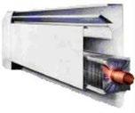
FOUR-PIPE SYSTEM
Page | 101
economical to install as the series loop system, in which piping is minimal. Again, the supply water temperature will be lower at the end of the run than at the beginning.
Hydronic Radiant Floors
Radiant floor heating systems conduct heat through the floor, which then broadcasts heat to every cold object in the room–especially you. It's an unparalleled sense of comfort, and the fuel efficiencies can be tremendous. Hydronic heating systems are clean, quiet, and can be installed under any type of floor covering.

Warm Air Heating Systems
• Select quiet motors and cushioned mountings.
• Do not permit connection or contact of conduits or water piping with the blower housing.
• Use a flexible connection between furnace and ductwork.


• Do not place the blower too close to a return grille.
Cooling Coils in Furnaces
The evaporator coil is the component in your AC system that absorbs the heat from the air inside your home. It is often either attached to your furnace or located on the inside of your air handler. It works with a condenser coil to complete the heat exchange process that produces cool air.
EVAPORATIVE C. SYSTEMS
Evaporative Cooling
Recall sensible heat / latent heat!!!
When water evaporates, it draws sensible heat from surroundings and converts it into latent heat in the form of water vapor
Conversion causes temperature to drop
Direct and Indirect Evaporative Cooling
Direct Evaporation Cooling Strategy water is sprayed into the air entering a building - this lowers the air temperature but raises its humidity Indirect Evaporative Cooling Strategies evaporation cools the incoming air of the building without raising the indoor humidity water is sprayed on the roof to cool the roof
Page | 102
Benefits
30%-90% less energy than conventional AC Equipment less expensive and no CFCs
Direct Evaporation
Increased humidity by adding water vapor to air increases thermal comfort in hot/dry climates


Best when in climates with >30o daily temperature range, >25o partially effective Greenhouses are the exception Humidity ok, high temperatures not ok
Examples
Evaporative coolers (swamp coolers) Very low energy use Simple mechanisms Misting outdoor spaces
Indirect Evaporation
Evaporation cools the incoming air of the building without raising the indoor humidity Multiple strategies
Evaporative Roof Pond
Indirect evaporative coolers Hybrid systems
Cool towers
Benefits
Can be used in humid climates
Can be used in climates with low diurnal temperature swings
Can be used for passive heating
Evaporative Roof Pond Strategies
Fixed insulation or floating (see HCL)
Different from radiant roof ponds - Use evaporation for cooling not radiation (not water bags / water is exposed)

Indirect evaporative coolers - Recent innovations include HMX (heat and mass exchanger), low energy

Hybrid systems
Cool the roof of a building (with water) so it can act as a heat sink
Does not affect indoor humidity level

Page | 103
Vaporized heat must come from roof itself, not the sun (night is best)
A hybrid system of radiation and evaporation
Cool towers
Passive evaporative coolers
Water sprayed on absorbent pads at the top of the tower
Warm air is cooled and drops
Cool air enters building Can increase performance by pairing with solar chimney Systems for Large Buildings
Larger buildings are typically internal load dominated
Interior areas of a building often have no thermal connection to the outdoor environment; allloadsareinternal .
All buildings, however, will have perimeter areas that interface with the outdoor environment through the building envelope.
A design challenge is to ensure that an HVAC system can respond to such varying needs.
Large buildings typically have so many thermal zones, and there are so many ways to move heat/coolth from one place to another and to introduce heat/coolth into a space, that literally hundreds of HVAC systems have been devised over the years.
MEEB 14.18 HVAC Systems for Large Buildings
(a) All-Air Systems (b) Air-Water Systems (c) All-Water Systems

Direct Refrigerant Systems
• Eliminates need to separate between Heating/Cooling production and distribution systems
• Heating and Cooling production is adjacent or within the area
• Used in skin-load dominated buildings with an extensive perimeter zone
• Small commercial buildings
SOURCE Heating
Wood heating devices
Gas-fired devices
Electric resistance heaters
Hot water boiler – (oil, gas or electric)
Warm Air Furnaces
Require distribution
Categorized based on direction of supply and return air
Hot water baseboards
Radiators
SOURCE Heating and cooling systems
• Fan coil units
• Packaged Terminal Air-conditioning units
Page | 104
• Heat Pumps (a reversible air conditioner)
• Air-air
• Ground source
• Water source
• Split systems
Mechanical System Exchange Loops
Heating Mode Cooling Mode
ALL-AIR SYSTEMS
In an all-air system, the heating/cooling effect is distributed from the source(s) to the spaces via heated or cooled air transported in ductwork; water is not used to transfer heat to/from the conditioned zones. The primary benefit of an all-air system is that air is used to modify the condition of air - the main issue to be confronted in some building projects is the spatial volume that must be allocated to the ductwork. Conditioned air is delivered to the various spaces through diffusers/registers. An all-air HVAC usually meets the owner's project requirements for thermal comfort, IAQ, and energy efficiency.


• Air is the only heat transport medium between the central mechanical room and the zones
• Characterized by big transportation conduits (ducts)- to reduce duct size, increase air speed (noise, friction, and cost)
• Best for comfort and;
• Allows for comprehensive distribution in the spaces
Advantages:
Heating/cooling media delivered via air only
Humidification & Heat recovery
Complex zoning
Close humidity & temperature control (exc. VAV)
Can use outside air for economizer cycle
Disadvantages:
Special care for maintenance access
Supplemental perimeter radiation may be needed
Higher volume of space needed
DISTRIBUTION systems – air only
Constant temperature, variable volume
Constant air volume Single-zone
Single-zone reheat
Page | 105
Constant-volume terminal re-heat multiple zones
Constant-volume dual-duct
Constant-volume multizone
Variable Air Volume Single-zone
Variable Air Volume Multiple-zone
Variable Air volume reheat terminals


Variable Air volume dual-duct terminals
Variable Air volume multizone
Fan terminal units
Fan coil units

Package terminal air conditioners
Single Zone all-air
In a constant volume system, air is delivered at the design airflow rate whenever the air-handling unit is in operation. A single supply duct leaves the AHU; it will divide into branches as necessary to deliver air to diffusers located in the zone. A large warehouse requires AHUs, and a home requires one for one zone.

-One thermostat controls several rooms in a single thermal zone

-Applications requiring air filtration and humidity control
-Uneven comfort for multiple rooms
Single Zone Terminal Reheat
If it weren't for the energy waste, this would be a very popular and effective system providing for acceptable IAQ, with good temperature and humidity control, flexible and adaptable. Several other all-air HVAC system types are in essence attempts to replicate the good points of a terminal reheat system while avoiding the energy waste. Illegal in most jurisdictions due to energy waste.
-One thermostat controls one room as a single thermal zone with a reheat coil control discharge air temperature
-Constant volume
-Poor energy efficiency
Multizone
This system mixes hot and cold air streams to provide appropriate-temperature supply air for each of several zones. Zone control is exercised at the air-handling unit (through the operation of mixing dampers). Then it must be conveyed to the zone separately so a separate supply air duct must run

Page | 106
from the AHU to each zone. Because of the multiple supply ducts, such systems will rarely exceed ten zones per air-handling unit. The distribution tree volume can grow to be HUGE!
-One thermostat controls discharge dampers to adjust air temperature to each room
-Small buildings with limited distances for duct runs
-Simultaneous heating and cooling
Dual Duct
Two air streams (“hot” and “cold”) are mixed under control of a zone thermostat in order to produce supply air that will meet the cooling/heating needs of the zone. The air streams, however, are mixed not at the AHU but in a mixing box located near each zone. There is no limit to the number of zones provided, changes in zoning are easily made without system- wide disruption, and the system is reasonably energy efficient.

-One thermostat controls mixing box for each room -Applications requiring precise control of temperature and humidity -Energy inefficient -High maintenance -Expensive to build
AIR-WATER SYSTEMS
In an air–water system, the bulk of the heating/cooling effect is distributed from the source(s) to the spaces via hot or cold water transported in pipes. Air is also supplied to the spaces from a centralized unit typically only enough air to ensure desired indoor air quality; this is often roughly 10% of the airflow seen in an all-air system. This air can also transport some heat/coolth. The primary benefit of an air–water system is reduced demand for distribution volume - piping is smaller than ductwork for equal heat transport. A concern in some building projects is the placement of water-to-air heat exchangers (the delivery devices) within the occupied spaces. An air–water HVAC system usually will meet the owner's project requirements for thermal comfort, IAQ, and energy efficiency.

• Most of the heating and cooling is accomplished by water
• Water pipes are smaller than air ducts
• Air is centrally and supplementary provided for fresh air and other air quality requirements
• Fan coil units are air and water systems.
Heating/cooling media delivered via air and water
Advantages
Page | 107
Produce comfortable results while effectively regulating IAQ, temperature, and humidity at reasonable first cost and with acceptable energy efficiency.
Air distribution allows for mitigation of indoor air pollutants through delivery of outdoor air. Water distribution allows for a substantial reduction in the size of distribution conduits.


Disadvantages
Because both air and water are used as heat-transfer media, these systems tend to be more complex than an all-air or all-water system.
Induction Unit Located below windows or above suspended ceiling. Advantages:


Page | 108
Flexible
×
×
Flexible Less
Low cost
× Noise × Poor
× Maintenance × Condensation
× Simultaneous
placement
Centralized humidity and filtration
Space heating Disadvantages:
Condensation
Noise Fan Coil Unit Fan draws air from room across coils Advantages
space
Disadvantages
ventilation/humidity
control
heating and cooling
Radiant Panels w/ supplementary air supply
Radiant heater panels work by using infrared heat to radiate warmth directly from the panel to the solid objects in the room. Not only are these wall-mounted radiant panels functional, but they are also a much more elegant and safe way to add supplemental infrared heating to an area than traditional space heaters.
Advantages Warm surfaces used to offset envelope heat losses.
Cool surfaces can be used to offset internal heat gains and/or envelope heat gains.
Disadvantages × Poor ventilation/humidity × Expensive × Not that popular in USA yet
ALL-WATER SYSTEMS
The heating/cooling effect is distributed from the source(s) to the spaces via heated or cooled water transported via piping and introduced to the spaces via heat exchange delivery devices. Air is not used - but air may be introduced to the spaces independently, for example by passive means. The primary benefit of an all-water system is that the spatial volume required for distribution will be the minimum possible (ducts are not used at all). In most nonresidential applications, an all-water system (without a means of air supply) cannot meet the ASHRAE definition of an air-conditioning system *Best reason for water systems is having no DUCTWORK! Pipes are smaller than air ducts

• Heating and cooling achieved by water into zones • Fresh air supply is either locally or independently provided • No mixing of air from other zones

Flexible
Require maintenance • Two or four-pipe systems
Heating/cooling media delivered via water only Advantages:
Page | 109
•
•
×
×
×
Flexible placement
Space heating Disadvantages:
Condensation
Noise
Code compliance
HVAC Systems Which ones for what buildings? MEEB 14.15 System Scales (a) Local Systems
(b) Central Systems
(c) District Systems
A local system is usually intended to serve one zone. The system is self-contained, located within the space being served, is typically of small capacity and small size, not commonly controlled from a centralized location. (e.g., window unit).
A central system serves multiple zones/one zone from one location. A distribution system is required to transport heating/cooling effect from its place of origin - mechanical room-to zones. A building may be served by one central system or by multiple central systems. (e.g., VAV system).

A district system serves multiple buildings, provides heating and/or cooling for campuses. The buildings being served usually have their own central HVAC systems. CUA’s new energy upgrade is an innovative example of a district system.
HVAC Criteria Selection and Application
There is no single correct HVAC system for most building types, no single correct way to arrange an HVAC system, and no single correct way to place the system into a building. Fortunately, many decisions that need to be made to properly integrate an HVAC system into a building are contextual, rather than technical, issues. This is the main reason for Enviro 2 category and why we learn about HVAC systems as architects.

Page | 110
The project architect usually knows more about project context than any other design team member. Some of the issues to be considered early in the HVAC placement process are whether the system will be
Local (requiring no central space allocation), Central, or district (where source equipment is remote from the building) system and Distribution of major equipment System location Central or Local?
-Local systems provide better control for a relatively large variation in environmental requirements
-Fast response time for change
-Built-in redundancy - Duplication of critical components so that there is no loss of capacity in the event of a failure.
-Require maintenance Central systems
-Larger buildings
-Equipment in a centralized space (easy accessibility)
-Economy of scale
-Expensive (initial cost)
-Low redundancy - Duplication of critical components so that there is no loss of capacity in the event of a failure.
Selection Criteria
Control capability and flexibility required Environmental requirements Cost of construction Energy consumption System efficiency
HVAC Systems Application Criteria
HVAC Systems Functional Criteria

Design Decisions
1. Establish HVAC-related owner's project requirements (OPR: design issues/intents/criteria; including code/standard compliance).
2. Establish zoning requirements.
3. Make a preliminary system selection based on the OPR and zoning requirements. 4. Calculate design heating/cooling loads.
5. Select appropriate source equipment (to meet loads, intent, and context).
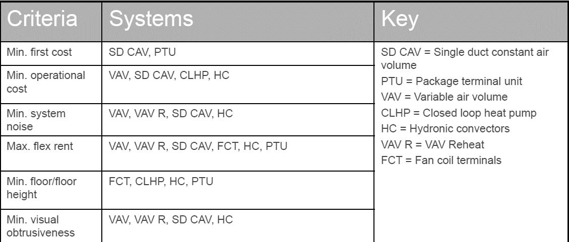
Page | 111
6. Select appropriate distribution approach (to meet intents and fit context).
7. Coordinate HVAC components with other building systems.
8. Rough-size equipment (fans, pumps, valves, dampers, pipes, ducts, condensers, air-handlers, tanks, etc.).
9. Run energy analyses to optimize equipment selections and system assemblies.
10. Final-size equipment based upon optimization studies.
11. Coordinate final individual equipment selections into a cohesive whole.
12. Develop appropriate control logic and strategies.
13. Develop commissioning test protocols and checklists.
14. Witness systems installation and verifications.
15. Develop systems manuals for the owner.
16. Provide benchmark (new system) performance data for the owner.
17. Assist in initial operations to maintain the owner's project requirements
module 3: lighting
Theories/Review Definitions:
There are five (5) different types of lighting systems:
Indirect illuminates a space indirectly using walls, ceilings
-Important to have white or reflective (diffuse) walls and ceiling.
-Ceiling and/or wall becomes the light source.
-Tends to be inefficient but very comfortable visual environment
Semi-indirect allows 60-90% to be indirect and 10-40% to be direct.
-Slightly more efficient than indirect but can have reflected glare (i.e., veiling reflections).
Direct-indirect provides roughly 50/50 split between upper (indirect) and lower (indirect) lighting.
-Care must be taken to limit brightness of fixture as this can cause glare.
General Diffuse Lighting is similar to direct-indirect except light comes off the fixture in all directions.
-General diffuse lighting tend to provide brighter environment that direct indirect illuminance.
-One problem with general diffuse lighting is that the bright fixtures can easily become a source of glare!
Semi-Direct uses 60-90°/o of the light downward with 10-40% upward.
-With a bright (white) ceiling semi-direct lighting can minimize glare by brightening the background and minimize energy loss due to indirect light.
Direct obviously means that all the light is directed in one direction (i.e., downward). Direct lighting is common in office building due to its ease of use with 2x4 grid.
-Direct lighting can cause problems with direct glare due to the exposure of the bottom side of the lens.
Page | 112
-Direct lighting can also cause problems with the reflected glare due to the strong downward component.
Glare Control
Controlling Indirect (Reflected) Glare: This can be accomplished by varying the candlepower distribution curve.
Plain diffuser: circular lighting distribution indicates a perfect diffuser. Direct glare can be a problem.
Good side wall illumination.
Indirect glare can be a problem.
Louvers and baffles: are usually rectangular metal/plastic. Improve direct glare by reducing side light.
Indirect glare is still a problem.
Prismatic and "Batwing": Improve reflected glare by reducing light heading at O to 45 degrees from nadir Also reduce light in glare zone. Can be problematic to clean.
Light sources: The efficacy of the light source is known as efficacy (lumens/watt)
Efficacy varies with: Type of light and Size of light
Types of lights: Daylight,Incandescent,Fluorescent,CompactFluorescent,HighpressureSodium,Low pressuresodium,Mercuryvapor,MetalHalide,LED
MEEB Table 8.1: Efficacy of Various Light Sources
Incandescent Lamps
Bulb nomenclature indicates type and lamp size
Lamp size: is measured in 1 /8". For example, (PS-52) = pear shape straight neck , 52/8 = 6.5"
Burning position: BU: base up BD: base down BU-HOR: base up to horizontal VER-BU: vertical to base up VER-BO: vertical to base down HOR: horizontal only Tungsten-halogen lamps are a more expensive halogen lamp (light heated filament). Quartz is used instead of glass to allow for higher operating temperature. A halogen gas (w/ argon) is used in the lamp to retard the evaporation of the hot filament.
Fluorescent lamps were developed to replace incandescent lamps based on their extended life and additional lumens
Fluorescent lamps work by heating and vaporizing mercury which causes an electric arc to form between the two electrodes: "Gaseous Discharge Lamp."
Linear lamps are tubular in shape, with the most popular versions being T8 and TS in standard and high output (HO) and the legacy T12 (38-mm) lamp.
Phosphor on the fluorescent tube walls changes the UV light into visible light.
Page | 113
MEEB Table 14.4 Comparative Characteristics of Tubular Fluorescent Lamps
Compact fluorescent lamps (CFL) represent a new development in fluorescent lamps.
CFLs have the lamp and the ballast all together in a standard mogul screw base for 120 VAC apps. The low-pressure sodium (SOX) lamp is used extensively in Europe. It has one of the highest efficacies. However, it is monochromatic yellow.
Low pressure sodium lamps are similar in appearance to fluorescent.
High pressure sodium (HPS) lamps are relatively new lamps that took advantage of space age ceramics and epoxy to allow for high temperature, high pressure sodium discharge.
HPS have pink light characteristics.
Light-emitting diodes (LED) emit light in very small bandwidths.
Individual LEDs are solid-state low voltage lamps. Most lamps have multiple LEDs. A single high-power LED can produce 7527 lumens with only 1 00watts: efficacy of 75 compared to 15 for incandescent.
DISTRIBUTION
Goals of Good Lighting Design
Lighting levels should be adequate for efficient viewing of specific task.
Lighting fixtures should be unobtrusive and should complement architectural design.
Lighting quality should be appropriate for the task (i.e., diffuse, direct, etc.).
Lighting design should be efficient ($ - cost, energy use).
Spectral Distribution of Light
Incandescent lamps unfortunately produce mostly heat.
Clear mercury vapor lamp have only a few mono chromatic spikes. We can improve this using phosphor into the outer lamp.
Metal halide approach the problem by adding the halides of metals to the arc.
High pressure sodium has the problem solved in the beginning due to sodium in the arc.
STRATEGIES
Library Lighting
Libraries comprise several different seeing tasks, each of which requires its own lighting solution.
-In the first, general lighting is supplied over the entire area, which is sufficient for reading tasks.
-For this purpose, LED, fluorescent or metal-halide sources are normally applicable, the latter with ceiling heights of at least 10 feet (3 m).
-The long life and high efficacy of these sources are suited to the long burning hours found in libraries. The second and more energy-efficient solution involves low-level general lighting supplemented by local reading lighting on the tables or in carrels.
Commercial Lighting
Desktop laptops, tablets, and so on, have become standard office items.
-While some hardware developments have been able to create matte, nonglare surfaces, there are still a considerable number of digital displays that have specular faces creating a special problem for office lighting that can become the deciding consideration in selecting the lighting system.
Page | 114
-The primary problem is to avoid reflection on the screen from any luminous source in the area, including luminaires, windows, illuminated walls, and even light-colored clothing. Any such reflection makes reading data on the screen difficult and sometimes impossible.
Industrial Lighting
A primary design consideration is cost. Given acceptable standards of comfort and safety for the working staff, additional costs for lighting must be self-justifying economically.
-In one case, a good lighting installation was improved at considerable cost
-Production jumped 15%, of which 3% was sufficient to amortize the cost of the lighting alteration.
-In another case, an outlay for new inspection lighting reduced product failures and proved economically sound.
-In a third, improved lighting reduced accidents, improved employee morale, and consequently improved production. The cases studied are far too numerous to mention; general principles are adduced instead! See Chapter 17 for more program-related strategies.
Calculations:
Lumen Method: a calculation procedure for determining the average maintained illuminance on a working plane.


-Calculate the Average Illumination for a room.
-Considers the room surface reflectance's – but assumes the surfaces are diffuse (not shiny!)
-Assumes an empty room (without furniture).
-Does not determine light fixture layout or location – you must following manufacturer’s spacing criteria or that in MEEB. Otherwise, use your best judgement in the layout!
Light levels are defined by; Codes, Owner, IESNA
1)Determine the required illuminance: E = 500 lux = 50 fc
2)Select the luminaire: this requires some assumptions about the criteria for classrooms.
-Selection Criteria (assume):
Low direct glare due to "heads up" position of students.
Low veiling reflections since student tasks involve high reflectance ... sometimes specular tasks. High efficiency luminaries to meet IES/ASHRAE standards.
Minimize maintenance.
MEEB Table 16.4 LED or 16.7 Typical Luminaires
Page | 115
3) Step 1: Record dimensions of room, reflectance, etc. into worksheet
4) Step 2: Determine the cavity ratios.

5) Step 3: Obtain the effective ceiling cavity reflectance (pcc) using MEEB Table 16.5 Percent Effective Ceiling/Floor Cavity Reflectance
6) Step 4: Obtain the effective floor cavity reflectance (pfc) using Table 16.2
MEEB Table 16.5 Percent Effective Ceiling or Floor Cavity Reflectance
7) Step 5: Determine coefficient of utilization (CU) from manufacturer’s data MEEB Table 16.7 Typical Luminaires


8) Step 6: Calculate the Light Loss Factor: LLF=A*B*C*D*E*F*G*H

Page | 116
9) Step 7: Calculate the number of fixtures. Assume uniform lighting.

Point Source Method: Calculating a point on a plane
Measuring Illuminance
Inverse square law: Illuminance from a point source is inversely proportional to the distance from the source. Lux (fc) = candela intensity/distance2 Candlepower distribution curves are made by rotating a light meter around a fixture at a set distance at 90⁰ Manufacturers are required to produce these. In the case of fluorescent fixture, candlepower distribution curves are required at 45⁰ rotations.
We can calculate the amount of light received on a surface perpendicular to the beam direction at a given distance from a point source: E (fc) = IΘ (cd)/distance2
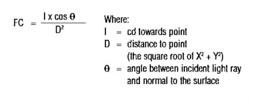

To account for non-perpendicular surfaces the point method adds the cosine factor to the inverse square law.

Point-by-point lighting calculations: E (fc) = IΘcos(β)/distance2 The luminous intensity (IΘ) in any direction can be taken off from a polar plot of the fixture intensity (i.e, candlepower distribution curve) or tables (IES files)
-These are usually supplied by the manufacturers
Abney’s law states that the total light arriving at a surface is the sum of the light arriving from all sources to which the surface is exposed.


Point calculations are done by hand only for simple situations, most commonly for small areas or vertical/horizontal illuminance.
-But if more points are needed, or there are more fixtures, then an excel spreadsheet or software is generally used.
Page | 117
Pythagorean Theorem: The square on the hypotenuse of a right triangle is equal to the sum of the squares on the two legs a2 + b2 = c2 Soh Cah Toa
Steps:
1)Find hypotenuse (or D)
2)Find angle of incidence (or Θ)
3)Look at manufacturers photometric data or MEEB and find the candelas at this angle
4) Solve for the FC level at the point

module 4: electricity
Electric Energy is a very high-quality energy and should be used with caution due to its high expense
-Prioritize passive optimization before deciding which renewable energy sources to use for electricity in building
Types of Electrical Systems
Thermal. hydraulic and electrical systems are said to be analogous in that they share similar characteristics. This is helpful in understand the systems.

Heat Conduction – R=Thermal resistance through a wall

Electrical Current going through a wall
Electrical Current (amps) = measure of flow of electricity flowing in a conductor (metal, etc.) Current (A, or Amps) is abbreviated I


V = Voltage Difference/Potential Difference; or potential represents the difference in electric charge between two points.
R Resistor can intercept the current (as a light bulb, etc.)
Page | 118
Rubber is a good insulator, not a conductor (Keep shoes on when working with electrical current!)
Electric Resistance (Ohms) is the resistance or "friction" to flow that particular device presents.

Good conductors: gold, silver, copper, aluminum
Good insulators: glass, mica, rubber, porcelain
Ohm’s Law: The current (I) that flows in a DC circuit is directly proportional to the voltage (V) and inversely proportional to Resistance (R)”

Current = Voltage/Resistance
Resistor Symbol

The object which presents friction to the current expressed in a relationship.
Current is directly proportional to voltage. Increase Voltage, you increase the Amps. While the Ohm (Resistance) stays the same

Current is inversely proportional to the Resistance. You increase the Resistance; the current Amps decline and the source which is being powered becomes dimmer.
Ohm (Resistance) doubles, Current Amps cut in half.
Ohm (Resistance) reduces by half, Current Amps will double
In these cases, we use the Incandescent Bulb but if you attempt to power an LED directly to an energy source, such as a 9V battery, it will EXPLODE.
The part that lights up is made from a thin tungsten wire that glows when it gets hot. The wire has resistance which limits the current automatically. This resistance is also what causes it to heat up.

Page | 119
LED does not have a static but "dynamic" resistance that decreases when the voltage applied to the diode increases. The current and power will become too high, and it will burst.
Relationships.
Increase Current by Increasing the Voltage.
Increase Current by reducing the Resistance. OR Reduce Current by increasing the Resistance.
Power = Work / Time
Power = Force*Distance / Time
1 WATT = 1 Volt * 1 Amp
Example: How many Amps does a 200-Watt incandescent lamp draw (resistive load =

A watt is the amount of energy that an electrical device (such as light) is burning per second that its running.
Watts measure Electric Power

Watts = Amps * Volts
W=I*V or W=I(I*R) = I^2(R)

Page | 120
115 Volts)? Assume 66 ohms.
POWER Basics
The Power Factor
Pf = Tells us how the alignment is for the current and voltage phases.
- In purely resistive loads (e.g., incandescent lights, electric resistance heaters) PF= 1.

- In loads like motors, computers, fluorescent lamps, PF= 0.7 - 1.0. The problem is that the power company puts W = V x I x (pf = 1) into the electric transmission system. However, the customer draws W = V x I x (pf =?) from the system.
Power factor is an expression of energy efficiency. It is usually expressed as a percentage and the lower the percentage, the less efficient power usage is
If a circuit were 100% efficient, demand would be equal to the power available.
When demand is greater than the power available, a strain is placed on the utility system.
Many utilities add a demand charge to the bills of large customers to offset differences between supply and demand (where supply is lower than demand). For most utilities, demand is calculated based on the average load placed within 15 to 30 minutes. If demand requirements are irregular, the utility must have more reserve capacity available than if load requirements remain constant.
PF expresses the ratio of true power used in a circuit to the apparent power delivered to the circuit.
A 96% power factor demonstrates more efficiency than a 75% power factor.

Page | 121
PF below 95% is considered inefficient in many regions.
Beer is active power (kW) the useful power, or the liquid beer, is the energy that is doing work. This is the part you want.
Foam is reactive power (kVAR) the foam is wasted power or lost power. It’s the energy being produced that isn't doing any work, such as the production of heat or vibration. The mug is apparent power (kVA) the mug is the demand power, or the power being delivered by the utility.
The power factor formula can be expressed in other ways:
PF = (True power)/ (Apparent power)
OR
PF = W/VA
Where watts measure useful power while VA measures supplied power. The ratio of the two is essentially useful power to supplied power.
Where the "pf' is the power factor that tells us how the alignment is for the current and voltage phases.
-In purely resistive loads (e.g., incandescent lights, electric resistance heaters) PF = 1.
-In loads like motors, computers, fluorescent lamps, PF = 0.7-1.0.
-The problem is that the power company puts W = V x I x (pf=1) into the electric transmission system. However, the customer draws W = V x Ix (pf=?) from the system.
ENERGY Basics
Energy represents how much total work is done by the system. In residences and in small commercial buildings the electricity billed is proportional to Electricity Use (kWh)= energy= power (kW) x time (hrs)
Over a period of a day this use equals the area under the curve. Where the "curve" represents the time varying instantaneous electricity use.
Electric Demand
The Load Factor is a ratio of the average: maximum.
L.F. = average power demand I maximum power demand
For example, in Figure 26.12, the peak demand (-15 min) is 6.5 kW and the average demand = 43 kWh/ 24 h = 1.8 kW.
L.F. = 1.8 kW/ 6.5 kW= 0.28
This means, on average, only 28°/o of the total peak load is used!
Load Factor is used by utilities to assess how their distribution and transmission lines are being used + Demand charge!
A $/kW charge is then levied for the kW measured.
Page | 122
At 5 $/kWh: 6.5 kW x $5 / kW= $32.5
The problem with electricity is that the electric companies need to recover the cost of the fuel they burn and the cost of the installed transmission lines, sub-stations, etc.
Obviously, the fuel burned is directly proportional to the (kWh) sold.
However, the cost of the installed transmission (and distribution) lines is proportional to the peak system load since the system must be capable of supplying all loads.
Each utility usually has their own way of calculating electric demand charges. These methods must be approved by the local Public Utility Commission (PUC).
Some of the basic methods include the following terminology:
- Fixed Period Demand Interval: A demand internal established to match clock time 10:00 - 10: 15, 10: 15 -10:30 ... etc.
- Sliding Window Demand Interval: In the past this was calculated by a little "motor-within-amotor" that reset itself every 15, 30, 60 minutes. Today, it is done with a microprocessor.
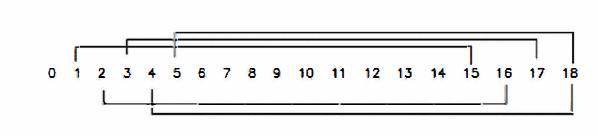
Measuring Electricity
• Electricity use is measured by sensing the magnetic field and potential difference in circuit.

• Unfortunately, since the current and potential is varying at 60 cycles per second this measurement must be an integrated measurement (i.e., time varying).
• The earliest meters (i.e., prior to the microprocessor) used a "small meter" which consisted of an eddy plate.
- One set records every revolution (kWh).
- The second set is separate gear train that resets every 15, 30, 60 minutes (i.e., kW or demand).
In the 1970's a digital watt transducer was created. Almost fill new electronic meters use this technology. It works by chopping the potential signal with a triangular wave which results in varying widths of pulses. These pulses are then multiplied by the corresponding height of the current signal.
-The kWh/unit time is then the area of the pulses.

Page | 123
In a series circuit – resistance is added System Voltage
There are two main types of system voltages used in residential systems: 120 V, 1 ɸ, 2 wire
120/240 V, 1 ɸ, 3 wire
In commercial systems there are also several additional systems:
120/208 V, 1 ɸ, 3 wire-not common 120/208 V, 3 ɸ, 4 wire 277/480 V, 3 ɸ, 4 wire 2400/4160 V, 3 ɸ, 4 wire
- ɸ - the phase refers to the distribution of a load.
Electricity is generated at a power plant
A power plant: an industrial facility that generates electricity from primary energy. Most power plants use one or more generators that convert mechanical energy into electrical energy in order to supply power to the electrical grid.
FOSSIL FUEL POWER PLANTS
Coal Power Plants

Coal-fired power plants accounted for about 37% of global electricity in 2018. Coal-fired power plants use steam coal as a source to generate electricity and consequently emit a significant amount of harmful gases into the atmosphere.
Diesel Power Plants
Using diesel as the fuel, this type of power plant is used for small-scale production of electric power. They are installed in places where there is no easy availability of alternative power sources USUALLY as backup for uninterrupted power supply whenever there are outages.
Gas Power Plants
Although natural gas is a fossil fuel, the emissions produced from its combustion are much lower than those from coal or oil, according to a study by the Union of Concerned Scientists.
GREEN POWER PLANTS

Nuclear Power Plants
Considered to be a low-carbon energy source + the technology is widely thought of as a more environmentally friendly option. Hazardous potential.
Hydro-electric Power Plants
Compared to fossil fuel-powered energy plants, hydroelectric power plants emit fewer greenhouse gases. But the construction of hydroelectric power plants and dams requires huge investment.
Page | 124
Hydroelectricity is produced by harnessing the gravitational force of flowing water. Compared to fossil fuel-powered energy plants, hydroelectric power plants emit fewer greenhouse gases. But the construction of hydroelectric power plants and dams requires huge investment.
Geothermal Power Plants
Geothermal power plants are considered to be environmentally friendly and emit lower levels of harmful gases compared with coal-fired power plants.
Solar Power Plants
Convert energy from the sun into thermal or electrical energy using one of the cleanest and most abundant renewable energy sources. But the initial costs involved in financing solar power plants are high and the installation requires a lot of space.
Tidal Power Plants
Tidal energy is generated from converting energy from the force tides into power and its production. Not used a lot. Although the development of tidal power is at the nascent stage, it has the potential to grow significantly in the coming years.
All these sources are AC – except for Solar Power
Solar power plant generates DC (then via inverter becomes AC)
Thermal Power Plants, Wind farms, Hydro Power plants and Nuclear Power plants, all produce AC power because the generator is a rotating component in all of these.
In the LAST class pp examples, both the voltage and current were assumed to be of a constant polarity, flow, and direction, in other words Direct Current or DC.

AC or Alternating Current’s voltage switches polarity from positive to negative and back again over time and who’s current with respect to the voltage oscillates back and forth.


The oscillating shape of an AC supply follows that of the mathematical form of a “sine wave” which is commonly called a Sinusoidal Waveform.
When using pure resistors in AC circuits that have negligible values of inductance or capacitance, the same principals of Ohm’s Law, circuit
Page | 125
rules for voltage, current and power (and even Kirchhoff’s Laws) apply as they do for DC resistive circuits…………. the only difference this time is in the use of the instantaneous “peak-to-peak” or “rms” quantities.

The rms or “root mean squared” value of an AC waveform is the effective or DC value equivalent for an AC waveform.
The schematic symbol used for defining an AC voltage source is that of a “wavy” line as opposed to a battery symbol for DC.

DC Examples
Cell phones
Flat screens (AC goes into TV converted to DC)
Hybrid/Electric vehicles
PV’s – use an inverter to convert the DC power produced by the modules into alternating current that can power lights, motors, and other loads.
AC Examples
Some household appliances (refrigerators, dishwashers, garbage disposals, & toasters)
AC powered electric motors
Since AC is easier to step up and step down (using transformers, which work only on AC), it has been widely adopted. This led to the usage of AC for commercial as well as domestic electrical appliances.
If V is low, I (current) is high (thicker wire)
If V is high, I (current) is low (thinner wire)
Step-up transformer: Increases voltage to decrease losses. What losses? Let me explain: Transformers are used to increase or decrease voltage by keeping the power constant. SO… We can transfer power in very low V OR Transferring power at very high V.


Page | 126
Copper loss = keeping copper to a minimum > requires higher V! Power Law (P = I*V)
High-voltage transmission line


Power at high voltages can help achieving lesser power loss, lesser voltage drops and at the same time improves system efficiency and reduces overall cost of power transmission. Transfers high V for LONG distances w smaller wires.


Step-down transformer (substation): Decreases voltage to safer levels be used in residences or businesses

-Local Distribution to smaller circuits for residences and businesses
Located on these are more transformers to further reduce the V for residential use. In USA it is 240V.
Large electrical appliances such as ranges, water heaters, clothes dryers, and air conditioners typically require 240 V, while120 V meets the needs for lighting, small appliances, TVs, personal computers, and convenience outlets.
o To distribute electricity efficiently, it is produced at high voltage between 2,400 V and 13,200 V.
o A transformer is then required to change the high AC voltage into a lower voltage for use at the building wiring (e.g., 120 V, 240V, 480 V, etc.).
o Example: A single phase, 100 kVA, 2,400/120V transformer will carry: l pc = 100,000 VA/ 2,400 V

Page | 127
= 41.6 A
lsc = 100,000 VA/ 120 V
= 100,000 VA/120 V = 832 A
Outdoor transformers do not need spatial requirements and reduce noise problems, but -It may be difficult to find a suitable outdoor location -It can be expensive if secondary voltage runs are long -Exposure to direct sunlight reduces efficiency -Ugly!!!
Indoor transformers give off heat that needs to be considered by the building ventilation system. The transformer vault is a fireproof enclosure that is used to house the oil-filled transformer and electrical switch gear.
The voltage and frequency of alternating current (AC) electricity used in homes varies from country to country throughout the world.
Most of the world uses 220-240 volts.
Power poles or underground lines transmit power at much higher voltages and is stepped down by transformers before the power enters a building’s main electric panel.
Electric Service to Buildings
-Public utility companies are usually only required to provide electric service to the customer's property line.

-Bringing the power into a building is either done overhead or underground.
-Overhead Service Drop is the name for a service entrance that utilizes overhead lines. -Underground Service Lateral is the name for a buried electric utility supply.

-Underground fill usually requires plastic conduit and concrete or metal conduit or direct burial. Under highways, streets, and other high-load areas, cable should be installed in metal conduit.
Conduits
All exterior wiring runs must be water-tight and weather-proof, and conduits provide this. In commercial buildings all 120+ voltage wire is required to be in conduits. This requires even more thought to consider:
- Circuit layout
- Electric risers

Page | 128
- Access to conduits, etc.
Conduits are installed and then the wires and cables must be poled through the conduits.
A decorative conduit (e.g., raceway) is designed to provide an aesthetically acceptable passageway for wiring without hiding it inside or behind a wall.

-Raceways are installed before wires. Wires are pulled in later.
Three types:
- Buried in the structure
- Attached to the structure
- Part of the structure
SERVICE DROP TO YOUR HOME
The 240 volts > TO YOUR HOME through a watt-hour meter, tracked by the power company via your watt-hour meter. Now, automatic via the smart grid –smart meters. ABOVE OR BELOW GRADE!


A system ground serves as an alternate path for the current to flow back to the source, rather than go through anyone touching a dangerous appliance or electrical box which would result in electrocution.

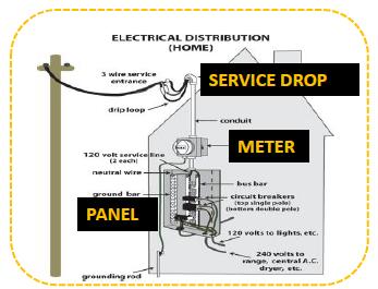
Current
Direct Current (DC) is what is produced with batteries and photovoltaic solar cells and D. C. generators (alternator + rectifier). Direct current has constant current in which the voltage = constant.
Alternating Current (AC) is what is used in households. AC is produced by a spinning motor/generator where a force is applied to turn the motor. AC is produced by passing a loop of wire through a magnetic field. The voltage alternates + to - to + 60 times/second (U.S.): 60 hertz.
Page | 129
Conductor is fancy way of saying wire
module 5: acoustics
Sources + Strategies of Acoustics
Other Factors in Hearing
Directivity is the ear’s ability to detect where a sound is. -Occurs in near and free field -Does not occur in reverberant field. -Almost completely dependent on higher frequency.

Level and Intelligibility is much higher in front of a person
NOISE
Basics
Speech as a sound source
-Speech ranges in frequency: 50-8000Hz
-Human Speech composed of Phonemes
Phonemes: distinct sounds and consist of English: Consonants and Vowels.
-Consonants carry more information than vowels; Consonants are higher frequency sounds and therefore are attenuated more easily than vowels.
-Consonants (higher frequency) are also directional and do not reverberate well (no diffraction) -Most speech energy is concentrated in the 100-600 Hz Range Noise
Annoyance is a result of:
-The loudness of the noise
-Greater for higher frequency (vs. low frequency)
-Greater for intermittent noise (vs. continuous noise)
-Greater for pure tone (vs. broadband)
-Greater for moving source (vs. fixed)
-Much greater with information content
-To define acceptable background noise; we consider: loudness and frequency and we ignore intermittent, pure/broad, moving, and information content
Two concepts have been used to determine and/or rate noise devised by Beranek:

-Articulation Index and -Speech Interference Level (SIL)
Articulation Index (Al): "is determined by reading a carefully selected set of phonetically balanced nonsense syllables to a test audience in the presence of different levels and compositions of background noise."
-Articulation index (Al) = correct answers / total syllables
Page | 130
-Al > 0.5 ~ "perfect intelligibility could be expected"

Speech Interference Level (SIL) is the arithmetic average (dB) of background noise levels at 500, 1,000, 2,000 and 4,000 Hz.
Noise Criteria Curves (NC) were also developed by Beranek to represent the maximum allowable continuous background noise at the level specified.


-To apply NCs to a space, octave band measurements are made and plotted.
-The lowest NC curve not exceeded is the NC rating.
Advantages:
-Single number spec. for entire spec.
-Derived for speech
Disadvantages:
-Derived for speech in continuous noise
-Not useful for “information content” noise
Occupational Noise Exposure

-Continuous exposure to high levels of noise causes some temporary deafness in most people.
-Long-term exposure causes permanent deafness.
-Continuous exposure to levels as low as 75 to 85 dbA can cause physical problems such as headaches, digestive trouble, and anxiety.
-In 1969 the Walsh-Healy Public Contracts Act was passed that limits the exposure to noisy environments.
-This is now enforced by Occupational Safety and Health Administration (OSHA) as maximum continuous exposure levels.
When the typical industrial noise levels are exceeded: Reduce the exposure time and attenuate the noise level.
MEEB Table 22.6 MEEB Fig. 22.19 MEEB Fig 22.21
Sound Absorption
-When sound energy impinges on a material part is reflected, the remainder is absorbed, or transmitted Ii=la (absorb)+Ir (reflect)+1τ:(transmitted).
Page | 131
-In general, we are concerned with the amount of sound energy that is absorbed since it is lost from our hearing.
-Every material has an absorption coefficient defined by: α= la /Ii where, Ii= sound power intensity impinging on a surface (W/cm2) la=sound power intensity (W/cm2) absorbed by the material.
α =sound absorption coefficient (%)
If α =1 0, all impinging sound energy is absorbed
Total Absorption (A=Sabins)
A = Sα where, A= total absorption (sabins (ft2)) S= surface area (ft2)
α= sound absorption coefficient


1 sabin (m2) = 10.76 sabin (ft2)
Total Room Absorption (A=Sabins)
ΣAi= Σ Siαi
= S1α1 + S2α2 + S2α2 …Snαn where, S1, S1= area of each material (ft2)
α1, α2= sound absorption (%) coefficient of each material A1, A2= total absorption of each (sabins (ft2))
How do materials impact sound?
The red arrows sound is conducted from their side to your side. Rigid drywall is rigidly connected to the wall studs, which are rigidly connected to your drywall. The vibration conducts straight through. The blue waves indicate airborne transmission.

Page | 132
MEEB
Table
23.1
–
Octave Band Average Sound Absorption Coefficients
Their drywall is vibrating back, and forth which produces a sound wave in the air cavity. This, in turn, vibrates your drywall and recreates the sound on your side. The drywall becomes a giant diaphragm and acts exactly like your stereo speaker moving back and forth.


Reverb: Reflected sound when the originating sound has stopped; The seconds it takes for reflected sound to die down by 60 decibels from the stop of the original sound.
module 6: conveyance

Theories/Review Definitions: Water
Supply + Distribution
MEEB Fig 20.1
With significant on-site treatment and recycling, potable water usage could drop by around 40% and the and residential public sewage treatment disappears.
Indoor Water Consumption
Reduce Water consumption in the building design
Specify water efficient appliances

-Efficient dishwashers use 20% less water
-Efficient clothes washers use 50% less water
Keep hot water heated inside thermal envelope
Keep distribution piping inside thermal envelope; insulated or will affect thermal cooling

Indoor Water Consumption Rates

Page | 133
Dual-Flush: Help to reduce water consumption indoors.
Pre-rinse +Aerator: Help to reduce water consumption indoors.
Process Water: Water that is used for industrial processes and building systems, such as cooling towers, boilers, and chillers. It can also refer to water used in operational processes, such as dishwashing, clothes washing, and ice making.
Condensate: Water which is in small quantities discharged from the HVAC

Composting Toilets: toilets that manage the breakdown of human excrement, paper products, food waste, and other carbon-based materials; waste is converted to “humus”, a soil-like product that can be used as a fertilizer for non-edible agricultural crops
(+) Reduce use of potable water
(+) Reduce load on sewer / septic systems
- Rely on aerobic bacteria and fungi to break down waste (same process as yard waste composting)
-Oxygen must be added either by turning or raking the waste or adding sawdust, straw or bark
-Proper ventilation of catchment area is required
-Sizing guidelines in Green Studio Handbook
Calculations
Steps for Plumbing
MEEB Table 18.3 Minimum Number of Plumbing Facilities
1. Identify the main occupancy class of your building (see Chapter 3 of International Building Code)
2. Identify your total occupant load (see Chapter 10 of International Building Code)
3. Divide your occupant load in half (50% Male/50% Female)

4 Determine the amount of required fixtures from chart (see Chapter 29 of the International Building Code)
a. Water Closets
b. Lavatories
c. Drinking Fountains (typically 1, but for restaurants serving water = 0, occupant load < 15 = 0)
d. Service Sink
Calculation Example:
Selectanaturalgaswaterheaterfor a four-bedroom house with 2 ½ baths. (MEEB Table 19.8) -40-gal storage cap - 38,000 Btu/h input

Manufacturer’s cut sheet & look at capacity

Page | 134
Sizeawaterheaterfor a women’s dorm with 300 students. Use two assumptions:
1. Assume a minimum recovery rate
2. Assume ½ maximum recovery rate Design;
-The heater
-The storage tank (MEEB Figure 19.23) Find empirical curve for each type of application that predicts the gal/hr and storage capacity.


Assume a minimum recovery rate. (Meeb Fig. 19.23)
-1.1 gph/student x 300 students = 330 gph recovery -12 gal/student x 300 students x (1/0.7) = 5,150-gal storage
Usable" storage capacity is 70% of the capacity shown on the graph. This is a safety factor.
Redo the same calculations using 1 /2 of maximum recovery rate:
-2.2 gph/student x 300 students = 660 gph recovery -6 gal/student x 300 students x (1/0.7) = 2,571-gal storage

Designandsizethepipetosupplyseveralfixtureslocated at 30 ft above street level, that require 15 psi and 10 gpm to operate.
1. Fixtures need 15 psi and 10 gpm
2. 30 ft of lift= 30 x 0.433 = 13 psi
3. Pressure drop through meter is from Figure 19.63
-Using 10 gpm through 1" meter probably a little low but O.K. for example
-Meter produces 1 psi
4. Calculate the Total Equivalent Length of pipe (TEL).


First add up all the pipe segments: 50 + 25 + 25 + 25 + 100 + 30 = 255 ft Next, determine the equivalent length of pipe for all the bands, joints, and valves, etc. that the water passes.
We use Table 19.16 for this with an assumption of a pipe size (for this and the meter).
-Add length of pipe w/ TEL
Page | 135
5. Now, change the ft. of TEL into psi
MEEB Figure 19.64 is a friction loss chart for smooth pipe.


Find: Velocity, Diameter, or Flow.
6.Now, add all psi together to see if system works.
Fixtures = 15.0psi
30ft lift = 13.0 psi
Meter = 1.0 psi
TEL = 10.5 psi
Total = 39.5 psi
This works because the city is supplying 50 psi to the building.
Water Supply
The stages can be classified as follows:
Filtration: removes additional suspended (i.e., won't come out with gravity).
Permanent media filters
Cartridge filters
Reverse osmosis filters
Activated charcoal filters
Disinfection: usually involves chlorination by bubbling chlorine gas through the water.

Alternatives: iodine, powerful ultraviolet light, ozone and boiling/distillation
Corrosion Control: Long-term exposure to water can dissolve certain metals. This can be prevented by controlling:
Acidity: pH of the water acid = corrosive
Dissolved minerals and salts leave deposits, increase cond.
Oxygen content accelerates corrosion.
Carbon Dioxide forms carbonic acid.
Softening Water: removes “hard” water with high calcium and magnesium.
Page | 136
Nuisance bacteria and algae control: keep water out of sunlight and cool.
Water at 80 - 110 F can form Legionella pneumophila ... always need to apply chlorine and/or bacteriacide and/or heat +140 F.
Fluoridation: Dental studies have shown that Fluoride in city water reduces tooth decay.
Problem is reverse osmosis removes Fluoride.
Distillation: boiling and distilling of water produces the purist water (and most expensive at ~1000 Btu/lb)
DHW Systems (Domestic Hot Water): Estimation of demand is accomplished by knowing number of baths, number of bedrooms, and heater type.
WASTE
Piping, Fittings, and Accessories
Meeb 20.12
(a) Connection of cast-iron piping. (b) Coupling to connect copper tubing.
(c) Connection of vitrified clay piping.

(d) Detail of house trap fitting.
(e) House drain, house trap with cleanouts and vent (fresh air inlet), and house sewer.


(f) Cleanout showing removable threaded plug. For large buildings, the term building drain, building sewer, and so on, supplant the terms house drain, house sewer, etc. Local codes differ on inclusion or omission of the house trap.
A multistory installation with each fixture vented; + for a single-story, back-to-back installation. MEEB Fig. 20.15
Drainage
MEEB Fig 20.8 Function of a trap and one of the several functions of a vent, preventing siphonage.
Waterless Toilets and Urinals – Composting
Page | 137
Sanitary Plumbing Systems
Sanitary sewers must be connected to: Septic tank and leaching field
Approved municipal sewage system
Septic Tank Systems: treat sewage from residences and small commercial buildings with anaerobic digestion (without oxygen)
Some filtering takes place in the septic tank where solids are trapped.
Remaining liquids (most household sewage is liquid) are then sent into the drain field where they are absorbed below ground level. (MEEB Fig 20.33 + MEEB Fig 20.37)
Leaching Field: A typical septic system consists of a septic tank and a drain field, or soil absorption field.
Service Core
Multistory construction, especially in office buildings, is often designed to be flexible and free of random partitions that would interfere with the periodic renovation and reorganization of interior spaces.
Building “cores” contain elevators, stairs, and shafts for plumbing, mechanical, and electrical equipment. Cores are often placed in the central section of the building, freeing the surrounding areas for access to daylight.
Elevator
History
Of ALL the decisions made by an architect of a multistory building, few are more important than the selection of the vertical transportation equipment, which includes passenger and freight elevators.
1854-Elisha Otis demonstrates his safety brake at the Exhibition of the Industry of All Nations at the Crystal Palace in NY. Elevator ropes at the time were generally made out of fiber and if the rope broke there was nothing to stop it. The introduction of a safety brake helped alleviate the publics fear of falling.

Page | 138
1857-The first public elevator is installed at the E.V. Haughwout &Co. store in NY. It serviced five floors and traveled at an average rate of 40 feet per min.
1889-The first electric elevator is installed at the Demarest Building in NYC replacing the steam engine with an electric motor.
1894-The Otis Elevator Co. installs the first automatic electric push-button elevator.
1892-Early predecessors to the escalator are invented and patented. Jesse Reno’s “Endless conveyor or Elevator” and George Wheeler’s “inclined elevator”
1902-Flatiron building is built with elevators servicing 21 floors.
1913-Woolworth building rises 57 stories.
1920’s-Ward-Leonard system of electric motor speed and control allows for smooth transitioning between accelerating and decelerating
An ideal elevator system provides; minimum waiting time for a car at any floor level; comfortable acceleration; a rapid ride; smooth braking; accurate automatic leveling at landings; and quick loading and unloading at all stops. provide quick, quiet operation of doors; good floor status and travel direction indication (both in the cars and at landings); easily operated car and landing call buttons (or other devices); smooth, quiet, and safe operation of mechanical equipment under all conditions of loading; comfortable lighting; reliable emergency and security equipment; and a generally pleasant car atmosphere.
Types of Elevators
Traction Elevator
Gearless Traction Machine
Geared Traction Elevator
Machine-Room-Less (MRL) Elevator
Hydraulic Elevator
Roped Hydraulic Elevator
Conventional Hydraulic Elevator

Hole-less Hydraulic Elevator
Vacuum (Air Driven) Home Elevator
Traction Elevators:
-The Most Common type of Elevators.
-Cars pulled up by means of rolling steel ropes over a deeply grooved pulley, commonly called a sheave.
Page | 139
-The weight of car balanced by a counterweight
-Sometimes cars built in pairs and synchronized to move in opposite directions and serve as each other’s counterweigh.
-Traction elevators use steel cords or flat steel ropes a lot of traction elevators prefer the use of flat steel ropes because they are extremely light due to its carbon fiber core and a high-friction coating and does not require any oil or lubricant. Because of these qualities, elevator energy consumption in high-rise buildings can be cut significantly.
Hydraulic Elevator
-No wires, cables, or overhead machinery is required for the In-Ground and Hole-less types. A machine room is required to house both the oil storage tank and the pump.
-The slow speeds of hydraulic elevators makes the ideal for freight elevators up to 50 tons.
Holed: This type has a cylinder that extends into the ground the same height to which the elevator is to be lifted.
Hole-Less: This type uses telescoping pistons on one or both sides of the cab to lift it. The cylinder stands within the hoist way and does not require a drilled hole. This class is typically limited to under 40’ of travel.
Roped: This type is similar to a traction type elevator. The cab is elevated by an attached rope that is pulled by pistons.
Elevators are governed by strict installation codes.
The main code in the United States for elevators is the American Society of Mechanical Engineers' ANSI/ASME Standard A17.1, Safety Code for Elevators and Escalators. The code has legal force in most parts of the United States.

-ANSI/ASME Standard A17.3 covers existing elevators and escalators, and
-Standard A17.4 covers emergency evacuation of passengers from elevators.
-International Building Code (IBC) Chapter 30
All elevator systems should be equipped with a complete safety system. Some of the safety features are:
Built in braking systems
A governor (speed monitoring device)
Electromagnetic brakes
And a shock absorber system
These subsystems are easier to install in roped elevator systems.
Another safety feature in most elevators is a sensor on doors that makes sure that nothing gets caught while doors are closing.
IBC Chapter 30:
Page | 140
3002.2 Number of elevators in a hoistway
3002.4 Elevator car to accommodate ambulance stretcher
3002.7 Common enclosure with stairway
3003.3.2 Number of elevators
3003.3.2.1 Three or fewer elevators
3003.3.2.2 More than three elevators (Strakosch and Caporale 324)

Calculations:
Calculatetotaltimeforanelevatortrip,waitingtime,andnumberofelevatorsneeded:
Given: 7 story building, typical floor height is 12ft, 500 fpm elevator, 22 passengers up, 22 passengers down, Building Occupancy 1,500 people, 60in. center opening doors.
Required: Accommodate 20% of building occupancy during 5 min peak rush, Interval (waiting time) between 40-50 sec
Total Time= Time up + Time down + Standing time

Time Up= (Running time per floor) X (Number of stops) Calculating Running time/ floor


Standing time= Lobby time + Transfer time + Door operation time Lobby time=


Page | 141
18 sec for 20 people + 1.6 sec for 2 additional
Transfer time= 3 sec for 2 passengers
+ 1 sec every additional
3+1= 4 sec/stop x 6 stops= 24 sec total time
Door operation time for 60 in center open door= 6.5 sec/stop x 6 stops= 39 sec 19.6 sec lobby + 24 sec transfer +39 sec door = 82.6 sec Add 10% for inefficiency= 82.6 x 1.10= 90.86 sec
In this instance, running time is equal to the running and standing time down:

Running Time Up=26.4 sec
Standing Time Up=90.86 sec
Running Time Down=26.4 sec
Standing Time Down=+ 90.86 sec
Total round-trip time=234.5 sec
Passengers up=22
Passengers down=+ 22 Total # of passengers=44
1 Elevator= 44 people/234.5 sec
Howtolayoutelevators:
1. Table 31.6 MEEB
2. MEEB31.25 to determine the elevator LBS!!!
3. MEEBTABLE 31.9 Elevator Equipment Recommendations
4. Elevator selection for occupancies –31.31


Signaling Fire
Fire Protection: The size of fire-fighting systems are now being designed to be smaller and efficient.
-As the average size of fires within buildings continue to decline the emphasis in fire protection is shifting to minimizing water and smoke damage.
-There are basic design considerations for fire protection and smoke management. Fire in a building has 3 needs:
-Fuel: building structure and contents
-High Temperature: control with water
-Oxygen: control with ventilation, foam, etc.
Fire usually has 3 sources of ignition:
-Chemical: spontaneous combustion
-Electrical: electrical heaters, sparks, arcs, etc.
-Mechanical: usually friction and/or over-heating of machinery
Smoke and gases cause 75°/o of deaths by building fires. Flame, heat cause 25%. Therefore,itismost importanttocontrolsmokeandgasesandcontrolflameandheat.
Fire produces:
Page | 142
-CO ... Carbon Monoxide - a product of incomplete combustion (causes suffocation)
-CO2 ... Carbon Dioxide - a product of complete combustion (causes excessive breathing)
Dangerous gases: Hydrogen sulfide, Sulfur dioxide, Ammonia, Cyanide, Hydrogen Chloride
Fire also reduces (02) oxygen content:
-Normal at 21 °/o
-Muscular use diminishes at 15%
-Judgement reduced at 10 - 14%
-Fatigue and collapse at 6 - 10%
Unfortunately, this means that when people are present, and fire breaks out it is difficult to starve the fire and provide oxygen for people to breath
Protection of Life: For most buildings one of the main goals of fire protection is to allow all occupants to exit the building between the time of the detection of the fire and when the fire department arrives.
-Protection of life is accomplished using several basic principles:
-Provide clear pathways to fire exits.
-Keep fire exits clear of smoke.
-Control the distance to the exits.
-Control the number of people that must use one exit.
-Make sure people who enter fire exits can make it to the "exit discharge" ... (i.e. outside)
Special considerations must be given to buildings greater than seven stories ... i.e. fire exits must accommodate people (dn) and fireman (up).
MEEB Table 25. 2 summarizes fire requirements for interior finishes.


MEEB Table 25.3 contains distances to stairs.
20/75 = 20 ft for common path serving > 50 people, 75ft for common path serving < 50 people
Protection of Property:
-Ideally fire trucks should be able to approach each side of the building.
-If access is limited then the building must be protected with fire walls and internal suppression systems.
-Internal fire suppression systems must operate for 1-2 hours in order to be sure the fire department gets there.
-Water reserves are usually required to provide adequate protection and/or motor-driven pumps.
Compartmentation is the dividing-up of a space into fire zones using fire walls.
-Maximum floor area established by fire code
-Openings in fire walls must have fire dampers and/or fire doors of equal ratings.
-Concealed spaces are spaces such as areas over suspended ceilings, behind walls, etc.
-May require fire blocks
-Should use non-combustible material
-Should have fire detection/ -Sprinklers
Page | 143
Smoke Management
Smoke Management Systems: Smoke management systems reduce deaths and limit property damage by controlling the spread of smoke.
This is accomplished with:
-Confinement -Dilution -Exhaust
Fires are almost always accompanied by heat and smoke: This makes smoke rise and spread. Vertical openings become problematic.
-Confinement is where smoke is contained with fire walls and smoke barriers.
-Curtain boards help concentrate smoke near atriums so alarms will go off.
Fire Exhaust Systems: Fire exhaust systems use air velocity and pressure to contain smoke.
Fire Walls: The spread of smoke in an open seating office plan is difficult to control.
-Use of fire walls, fire doors and fire exhaust system can control smoke.
Suppression
Water is used most often for fire suppression for several reasons:
-It is inexpensive and readily available.
-It is very effective: Water absorbs 1000 Btu/lb as it vaporizes and cools the fire. As steam (water vapor) is created it pushes away oxygen.
Unfortunately, water has certain disadvantages:
-It is wet and ruins most building materials (wood, fabric, carpet).
-It conducts electricity and is thus a hazard with electrical fires.
-It is not as effective with oil fires since burning oil can float.
-It can burn fire fighters when it turns to steam.
-Water systems must have drains.
Standpipes and hoses are used to fight fires:
-By building personnel until firefighters can arrive ... usually needs water supply
-By firefighters with the assistance of pump trucks
There are two (2) types of systems:
-Wet-pipes always have water in them. System must be protected from freezing. -Dry-pipes have compressed air inside and fill with water when needed. These do not need to be heated.
Sprinkler Systems are similar to lawn sprinklers (i.e. water spray coverage).
Sprinklers automatically trigger at 25° F+ above the highest expected temperature (135, 175, 250 ... 650° F).
Sprinkler Types Include:
-Quartzoid bulb bursts at a specific temperature and emits water (must be shut off)
-Fused link usually plastic that pulls apart at a specific temperature and emits water (must be shut off)
Page | 144
-Flow control sprinklers turn on at a temperature and then turn off when fire is under control -Deluge types are always open so everything flows at once (must be shut off).
“Other" Fire Suppression Methods: Although water is the most common and effect fire suppression method, some buildings cannot use it due to damage from wetting by water.
Examples:
-High voltage electrical areas -Art museums -Cooking and/or kitchens
Examples of "other" fire suppression methods include: -lntumescent materials
-Portable fire extinguishers -Foams -CO2
-Halogenated agents
Portable Fire Extinguishers:
-Class A are water or water- based fire extinguishers for use on wood, trash or paper fires.
-Class B are fire extinguishers that are smothering or flame interrupting such as: CO2, Sodium, Foam, Halogenated agents, Potassium bicarbonate
-Class B fire extinguishers are for use on liquid petroleum or flammable liquids.
-Class C fire extinguishers are for electrical fires and include Dry chemicals, Halogenated agents, and CO2.
-Class A:B:C are "multipurpose" fire extinguishers and include Ammonium phosphate. Ammonium phosphate leaves residue on electrical fires.
-Class D fire extinguishers are for use on combustible metals: Graphite, Sodium chloride (salt). Foams and foaming agents are special purpose fire suppression methods. Special purpose foaming systems are often used in aircraft hangers, coliseums, and large industrial plants where water cannot be used.
Modern foam systems use patented foaming agents that can produce 1000: 1 ratio of foam: liquid. -Can produce 2000 ft3/sec.
-Work by reducing oxygen content to approximately 7% -Safe for people and fire fighters with cloth breathers.
Calculations:
Example: What exit capacity is required per floor? A multistory office building is 80ft wide by 300ft long.
The gross floor area is: 80*300=2400ft2
From Table 25.4, the occupant load per person is 100ft2

Population per floor: 2400ft2/100ft2/person) =240 people
Exit doors (to stairs): = 240 people * 0.2in/person = 48 in. total
Page | 145
Stairs: = 240 people * 0.3in./person = 72 in. total Sprinklers?
1. Determine the relative fire hazard (MEEB Table 24.8)


2. Determine sprinkler coverage (MEEB Table 24.9)

-Use relative Fire Hazard Rating -Determine area (ft2) or maximum distance -Sprinklers use 0.1 gpm/ft2 (light) – 0.5 gpm/ft2 (extra hazard)
3. Layout and Size Piping (Steel or copper)
-One fire department connection or each frontage -Master water valve for all other water connection
-Firewalls to protect non-sprinklered areas -Slope floors, drains, scuppers for water
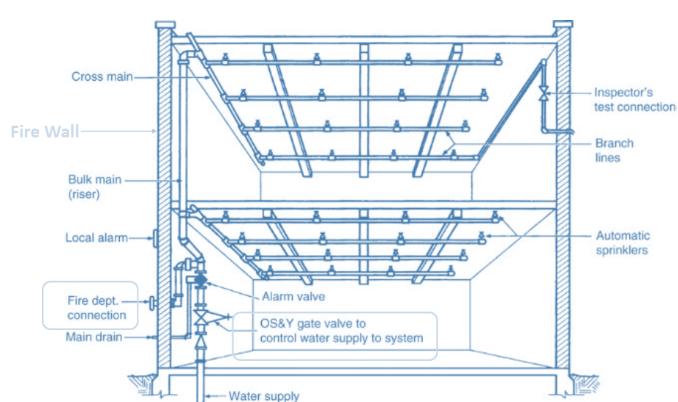
Typical Design: -125 ft2/sprinkler
-Siamese fitting for 2 pump trucks (1000 gpm each)
-Protect Siamese fitting from freezing
-Use check valves to control flow direction
Page | 146
closing: design process
As architects, our responsibility to human health and safety and to the environment is upheld by our knowledge and ability to execute a balance Integrating metrics as environmental controls with ethics creates resilient building design. It is vital to consider this integration through every step of the design process and implement each lesson in each appropriate step.
https://hmhai.com/faq-items/design-phases/
appendix: resources
ENVIRONMENTAL DESIGN I module 1 – foundations

HCL Ch 1 + 2 Heating, Cooling, Lighting, V 5 HCL Ch 20 Integrated Design Process module 2 – principles
HCL Ch 2,3 module 3 – climate
HCL Ch 4,5 Climate consultant 6.0 module 4 - solar HCL Ch 6
https://www.susdesign.com/ module 5 - energy
HCL Ch 7 Passive Solar HCL CH 8 Active solar module 6 - wind HCL Ch 8 module 7 – envelope HCL 13+14
Page | 147
module 8 – lighting
HCL Ch 11 + 12 module 9 – materials
Recycling: A Comparison
https://www.youtube.com/watch?v=GM08JabFnpU
Green Buildings + Health
LEED Materials and Resources Credits (read all of their descriptions) https://www.usgbc.org/credits/new-construction/v4/material-%26-resources
TALLY
module 10 - site
HCL Ch 10 module 11 - water
GSH CH 4 Water & Waste module 12 - synergies
HCL Ch 19,22
GSH CH 5, SWL Part IV Bundles module 13 - tools
HCL Ch 21 CODES + 24 DIGITAL module 14 - assessments
HCL Ch 20 IDP + 23 ASSESSMENT
ENVIRONMENTAL DESIGN II module 1 – synergies
MEEB Ch. 9, 10,11,12,13, 14.
MEEB Ch 12.5-12.8, Ch. 13 module 2 - hvac
MEEB Ch. 14.1 – 14.4- 14.20 module 3 – lighting
MEEB Ch. 15.1-15.22, 16+17, 6+10
HCL Ch. 11 + 16 module 4 – electricity
MEEB Ch. 25, 26, 27, 28, 29
HCL Ch. 17.1-17.12 module 5 - acoustics
MEEB Ch. 7, 22+23 module 6 - conveyance
MEEB Ch. 18, 19, 20, 21
Page | 148