Gatic Surface Water Drainage

Slotdrain Technical Brochure


DRAINAGE & Feb 2023

Slotdrain Technical Brochure


Alumasc is a UK-based supplier of premium building products. The majority of the group’s business is in the area of sustainable building products which enable customers to manage energy and water use in the built environment.
Alumasc Water Management Solutions provide ‘Rain to Drain’ solutions, that set the standard for urban water management. They include: Skyline Fascias, Soffit & Copings; Alumasc Rainwater Gutters & Downpipes; Harmer Building Drainage; Wade Building Drainage and Gatic Drainage & Engineered Access Covers.
Under the AWMS banner, customers benefit from rainwater and drainage products that capture, retain and control the flow of rainwater in the most effective way inside and outside buildings.
Gatic’s wide range of slot drains is backed by the fastest technical response and the most extensive support. Our hands-on approach ensures customers get the best support every step of the way, from technical design through to installation. Our technical team is also accessible for site visits.

We aim to turn around the design of drainage systems based on your drainage layout, complete with quantities and delivery time scales, within 24 hours.
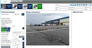
This interactive calculator allows you to design your own drainage system using the same programme as our inhouse technical team. Simply register an account at: calculators.alumascwms.co.uk


We have added our highly specified range of Slotdrain channels to Innovyze’s MicroDrainage software.
MicroDrainage is a well-recognised tool for civil engineers working on surface water and external drainage calculations. It is the industry standard software for the detailed design of fully integrated storm-water and foulwater drainage systems. Users of MicroDrainage benefit from a user-friendly interface, auto-design and optimisation as well as formal reporting and outputs.
Along with the usual functionality, MicroDrainage can be embedded within Autodesk’s Civil 3D software through the DrawNet(CAD) interface. This enables MicroDrainage to conduct intelligent data exchange through the use of Parts Lists, include Gatic Slotdrain Civil 3D, providing engineers with an ability to quickly, accurately and confidently exchange information between models, helping to achieve BIM Level 2 compliance.
We also offer CPD presentations at your premises or as webinars, covering all aspects of surface water drainage. Our presentations are accredited by the CPD Certification Service and count towards the continuing personal and professional development of attendees. It’s a factor worth bearing in mind for those individuals seeking professional membership.
The CPD presentations currently available are:
Visit www.alumascwms.co.uk for more information or to book your place.
Our technical product information is included in this dedicated library of manufacturers’ product information, contained within the UK’s industry leading specification products NBS Building, NBS Landscape, NBS Engineering Services and NBS Scheduler.

Products listed in NBS Plus are directly linked to specific clauses and can be imported instantaneously into a specification. NBS Plus contains over 20,000 product specifications and is updated regularly, so designers can be confident that they are always referencing the very latest product information.
Links of all Gatic products on the NBS Plus Product Register are available on our website.
www.alumascwms.co.uk
Our website now contains even more technical information and guidance than before. We have increased our online resources and improved the website design so you can now find all the technical information you need for your projects easily and quickly.

Within each product range, you can explore features and benefits, technical details, graphics, diagrams, and case studies.
By setting up an account (registering your name and email address), you can store all the literature, technical specifications and images that you have collected while browsing, and access them again anytime from your MyGatic page simply by logging in.
Our products have been tested in accordance with recognised standards, providing reassurance to industry professionals that our channel systems have proven performance. These include:
• Quality Management Systems ISO 9001 - the recognised standard for the improvement of product, process and service quality.
• European Standard EN 1433 ‘Drainage Channels for Vehicular and Pedestrian Areas’ - the only internationally recognised standard written specifically for trench drainage and slot drain systems. This uses the load classifications between A15 and F900.
Gatic is focused on providing effective solutions that enhance sustainability in the built environment. We are committed to adopting environmentally sound business practices throughout our operations and are well positioned to benefit from
environmentally-driven changes in policy and regulation. In particular, the growing awareness of sustainability and life-cycle cost among building and construction specifiers.

We work to the following standards:
BREEAM - the world’s foremost environmental assessment method and rating system for buildings. Design teams use BREEAM as a method to improve the performance of their buildings and their own experience and knowledge of environmental aspects of sustainability. Gatic’s channels have been used on a number of projects associated with BREEAM.
Quality Assurance
Gatic Slotdrain channels have been tested in accordance with recognised standards, providing reassurance to industry professionals that the system is fit for purpose. The system has proven performance, having been used successfully for many years on a variety of project types in many locations around the world.
Load Testing Standards
The only internationally recognised standard written specifically for trench drainage and slot drain systems is the European Standard BS EN 1433:2002 ‘Drainage Channels for Vehicular and Pedestrian Areas’. This uses the load classifications between A15–F900, as listed in the table below.
Load Tests
Gatic Slotdrain channels have been independently load tested up to F900 load class (depending on the system type) in compliance with the European Standard BS EN 1433. Certificates of conformity are available upon request.
Watertight Slot Channels
Gatic Slotdrain has been independently tested for ‘watertightness’ and complies with the European Standard EN 1433 ‘Drainage Channels for Vehicular and Pedestrian Areas’ – when installed within a channel concrete encasement/surround according to manufacturer’s details.
Gatic Slotdrain is mechanically assembled, which eliminates welding and minimises energy usage in the manufacturing process. A significant proportion of the raw materials used are from recycled sources. Slotdrain is manufactured from sheet steel and is 100% recyclable.
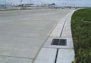
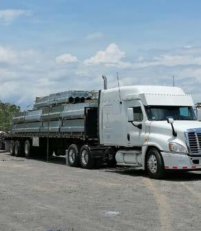
Slotdrain – Highly efficient surface water drainage for all applications, from airports to distribution hubs and urban landscaping.
Our market leading range of surface water drainage ensures we can provide the best solution for your commercial or domestic projects. Below are examples of applications our range can cover.
In a climate where we are experiencing more frequent and extreme rainfall, it is increasingly important our roads, pavements, motorways and other similar infrastructure are protected from the build up of excess rainwater. All our products are designed to manage the discharge of surface water efficiently and effectively.

Airports around the world are seeing movements increase year-on-year and aircraft weights reaching new heights. With super jumbos like the Airbus A380, airside drainage is ever more of a challenge.
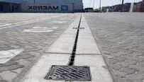
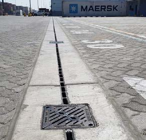
Large ports and dock facilities are occupied by heavy, slow moving cranes that place high demands on the surface drainage. Only products with the highest specification are fit for this purpose.

Container ports and distribution yards are extremely hostile environments, pounded continuously by tractor and trailer units. Our robust range of slotdrain systems have been specifically developed with this in mind.

Distribution yards and industrial units typically have large surface areas to drain and must cope with heavy loads manoeuvering on a daily basis.
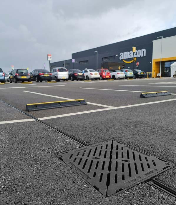
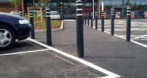
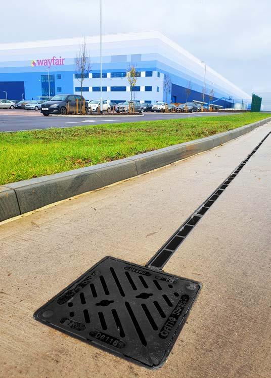
In car parks, slow turning traffic and a constant flow of vehicles make for a demanding and harsh environment for any surface water drainage system. Strength and durability of the slot or channel drain are essential in these high traffic areas.

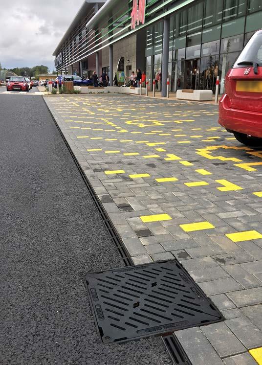
Shopping centres and retail parks need unobtrusive but effective drainage to maintain an attractive environment. Looks, style and performance are all important characteristics for these projects.
Bus terminals and public transport facilities place heavy demands on surfaces and infrastructure. Strength and reliability are key criteria.
Highways and motorways are under constant strain from heavy traffic and vehicles of various sizes. It’s important the surface drainage can manage large volumes of rainfall so that the road remains free and safe from excess water.


Petrol stations and forecourts mean wide open spaces and constant weight of traffic. Robustness of the slot or channel drain is essential.

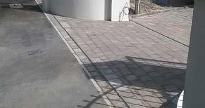
Landscaping and pedestrian schemes include domestic driveways and paved areas. For these projects the aesthetics and design of the slot drain is important to ensure it is discreet and fits seamlessly with the surrounding environment.

Our core business has traditionally been driven by our success in meeting the heavy demands of the world’s major ports and airports. Gatic’s Slotdrain* hexagonal channel profile was originally developed in conjunction with industry professionals from the airport sector.
The concept has proved infinitely scalable and has been developed into a comprehensive range of products suitable for smaller projects such as landscaping schemes, shopping developments and parking facilities.
The current Slotdrain range consists of CastSlot, UltraSlot , PaveSlot and FacadeSlot for total design flexibility, and includes complementary accessories. All channels are manufactured in 3 metre, 1 metre and 0.5 metre lengths of galvanised steel, benefitting from fewer joints and improved flow performance.

Bespoke units are available on request to suit specific design requirements and are also available in stainless steel grades 304 & 316
Gatic Slotdrain channels are suitable for applications up to F900 (depending on the system type). The hexagonal profile ensures our systems can handle everything from a rain drop to a rainstorm with similar efficiency. The V-shaped channel base aids a self-cleansing flow, and a tapered throat helps prevent blockages.
*Patented
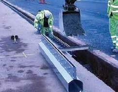
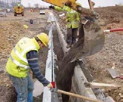
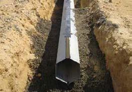
Our illustrated literature includes advice and general information on safe handling, installation and maintenance of our Slotdrain products.This can be downloaded from our website www.gatic.com. Alternatively, email or phone us to request a copy.
Discreet PaveSlot Top Neat aesthetics
Tapered Throat
Helps prevent blockages
End Caps
Available with preformed circular outlet knock-outs
Longitudinal Drainage Slot 10mm wide PaveSlot
V-Shaped Channel Base Aids a self-cleansing flow

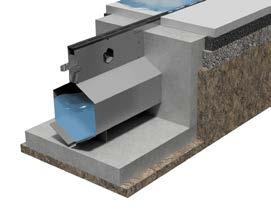
The unobtrusive profile of CastSlot sits neatly within concrete, asphalt and block surface finishes.

CastSlot features an electro painted ductile iron throat section, which is securely fixed to the galvanised steel channel body to provide an exceptionally robust yet discreet drainage system. CastSlot is ideal for areas of vehicular traffic such as car parks and industrial units where there is slow turning traffic. Available with a 30mm opening and a Treadsafe option, which reduces the slot opening from 30mm wide to 2 x 10mm wide slots. Protection Strips Provided.
Load classification A15 to F900
• Airports
• Ports and Docks
• Container Ports and Distribution Yards
• Bus Terminals
• Distribution Yards & Industrial Units
• Petrol Stations and Forecourts
• Highways and Motorways
• Car Parks
• Landscaping and Pedestrian Schemes
UltraSlot is used in external pavement areas such as airports, ports, highways and similar areas. The system is designed to withstand infrequent ultra heavy-duty loads.

A Treadsafe option is available, which reduces the slot opening from 30mm wide to 2 x 9mm wide slots. This has no effect on the intake capacity of the system but will make the channel safe to cross for pedestrians.
Load classification: A15 to F900 (Protection strips available)
• Airports
• Highways & Motorways
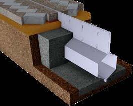
PaveSlot is used to drain external hard surface areas where a neat, unobtrusive aesthetic is required. The system is used with paving units laid against the top edge of the channel. The system is suitable for all paved areas, in public and commercial projects.
Load classification: A15 to C250 *
Applications:
• Landscaping and Pedestrian Schemes
• Shopping Centres and Retail Parks

* Higher load classifications are available, subject to site application and traffic conditions.
Please contact our technical departmet for further details by emailing us at: gatictech@alumascwms.co.uk
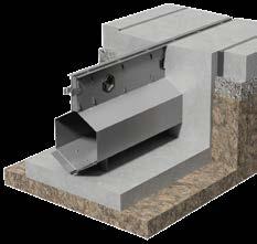
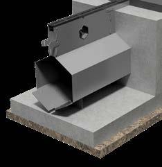
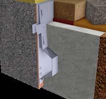
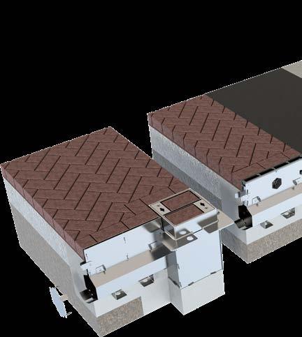
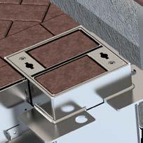
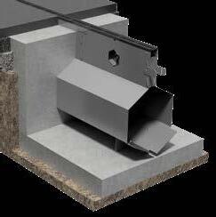
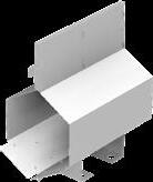
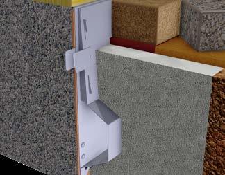
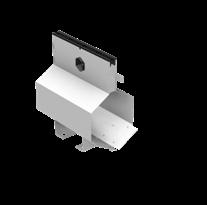
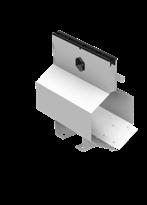
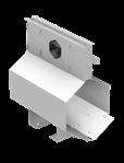
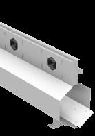
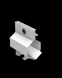
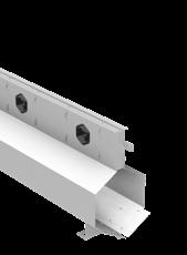
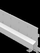
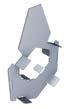
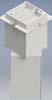
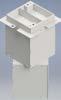
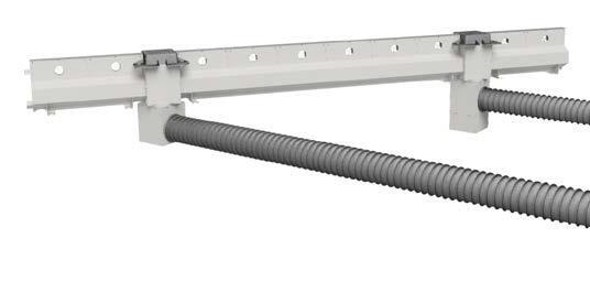
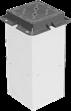
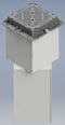
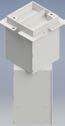
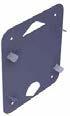
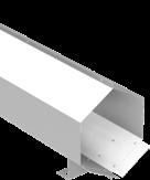
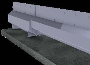
A discreet surface drainage channel that can be installed against a building, wall or other external landscape feature, to provide effective drainage from vertical surfaces, door thresholds and adjacent pavement areas.
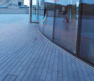
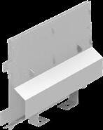
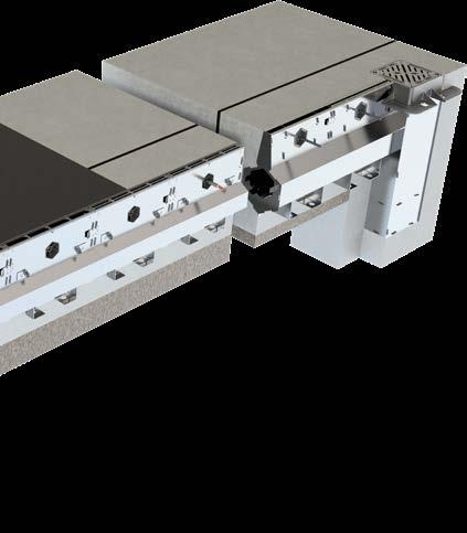
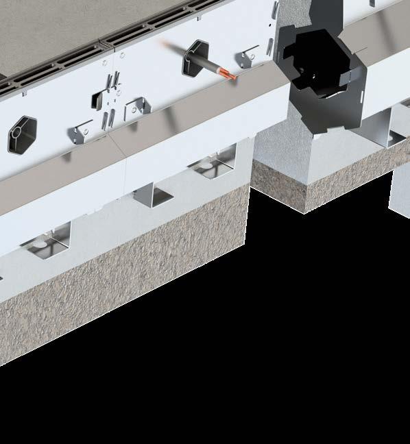
FacadeSlot channels can be made to follow the building perimeter whether straight or curved. The system can accommodate rainwater downpipes which, when positioned over a simple rainwater inlet box, can eliminate the need for a separate drainage network for the roof area, achieving a more efficient drainage system.
Load classification A15
Applications:
• Landscaping and Pedestrian Schemes

• Shopping Centres and Retail Parks
• Domestic
• Podiums


CastSlot Treadsafe 3m Channels
CastSlot Treadsafe 1m Channels
CastSlot Treadsafe 500mm Channels


PaveSlot 3m Channels
PaveSlot 1m Channels
PaveSlot 500mm Channels
* Higher load classifications are available, subject to site application and traffic conditions.

Please contact our technical departmet for further details by emailing us at: gatictech@alumascwms.co.uk
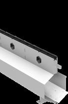
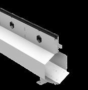
FacadeSlot 3m Channels
FacadeSlot 1m Channels
FacadeSlot 500mm Channels


The below range of standard accessories is available to suit all types and sizes of Slotdrain channels.
Cover and gratings are supplied with locking bolts for additional safety and security


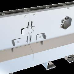
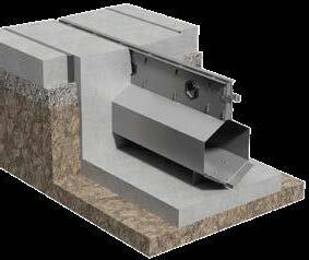
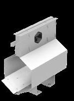
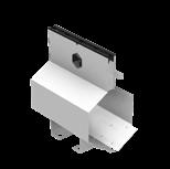
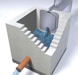
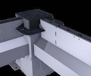
Driven by feedback from our valued customers we have designed a system that allows pipework to connect with our Slotdrain Outlet and Silt boxes at any given angle.
The Gatic Roto Modular range features a pivoting function that allows the lower section to rotate 45 in either direction.
Both include circular knockouts on all four sides to allow pipework to connect with ease.
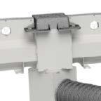

A reduction in bends/joints within the pipework allows for the surface water to flow more efficiently through the system. The silt box contains a removable bucket for effective silt and debris management.
Outlet Box C/W Treadsafe Double Triangular Grating
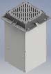

Double Triangular Grating


Roto Modular Silt
Modular
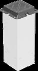
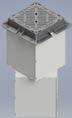
Outlet Box C/W Galvanised Recessed Cover
Roto Modular Outlet Box C/W Galvanised Recessed Cover
Silt Box C/W Galvanised Recessed Cover


Roto Modular Silt Box C/W Galvanised Recessed Cover


Available for all Slotdrain (for use with Gatic Access / Outlet / Silt Boxes)
*Made to order outlet size on all regulators


CastSlot /

Treadsafe / UltraSlot / UltraSlot Treadsafe / PaveSlot Catchpit Connector
/
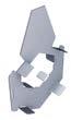
Treadsafe / UltraSlot / UltraSlot Treadsafe / PaveSlot / FacadeSlot End Caps / End Cap Outlets
 CastSlot
Tests undertaken by an independent hydraulics consultant indicated that the intake capacity of slot channel systems compares favourably with that of surface channel systems with conventional slotted gratings. Test results are available on request.
When designing a drainage scheme, professional engineers will most often choose a worst case rainfall intensity rate experienced over a period of 10 years or longer. This ensures that the system can accommodate the most severe storm event.
The intake capacity of each type of Gatic Slotdrain system is much greater than would be required in almost all realistic situations, despite the fact it only appears as a very neat 10 or 30mm wide slot in the pavement. The table right shows intake capacities for Gatic Slotdrain with surface water flowing to both sides, or from one side only (flow interception on a slope).
The design and requirements of a surface drainage system will vary according to geographic location. Some regions may experience very low levels of rainfall throughout the year, so drainage systems can be designed to capture and conserve water, which may be viewed as a valuable commodity. Other regions may experience long periods of adverse weather conditions, with high and prolonged rainfall rates. In these areas, drainage systems can be designed to quickly and efficiently dispose of surface water. However, the flow of water away from the channel system or site may have to be regulated in order to reduce the flood risk of rivers downstream of the site.
Gatic Slotdrain can be incorporated within the drainage scheme of urban projects to assist with the efficient collection and re-use of water. This provides construction industry professionals with a simple and effective method of water storage and flow regulation.
Gatic Slotdrain channels are available up to 600mm wide, the largest unit having a water storage capacity of 405 l/m. By including larger Slotdrain channels in a surface drainage design, individual channel runs can be used to store higher volumes of water immediately after rainfall occurs. Stormwater may then be diverted to a larger water storage facility on site to conserve water. The flow of water away from the channel may be controlled to meet regulations regarding stormwater discharge from sites. Gatic Slotdrain provides the greatest advantage when ‘close to source’ water storage is required.
Examples are:
• Depth restrictions on site for pipe inverts, or no space to install a deep water attenuation tank.
• Water storage required at a shallow invert.
• Rocky ground so deep excavation is restricted.
• High water-table.
• Areas of site infill.
The easiest and most cost effective way to control water flow away from a slot drain channel system is through the use of an orifice plate, fitted to the catch pit of the channel system or to access units along the channel run. The methodology and hydraulic performance of the orifice plate is well proven and well understood. By designing the size of the orifice within a blanking end plate, maximum flow levels can be established and controlled.
If you are considering using Gatic Slotdrain for water storage, or if you wish to design a slot drain system where the flow will be regulated, please use the AWMS Hydraulic Design Software, or contact our technical department who can provide details of the size of orifice required to achieve the flow rates requested.
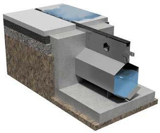
Flow Regulator:
In order to control the flow of water away from the Gatic Slotdrain channel, a Flow Regulator accessory must be used.
Flow Regulators are supplied by Gatic in Grade 304 stainless steel, and are available in a variety of sizes to fit specific channel widths.
The Flow Regulator accessory supplied by Gatic incorporates a semi-circular sharp edged orifice, which is located at the invert level of the nearest slot drain channel, to ensure that there are no restrictions to flow in normal operational conditions. If the orifice becomes blocked with debris, the Flow Regulator also incorporates an overflow weir at the top of the unit. This ensures that the channel system will not become totally blocked, which could cause surface flooding.
A Flow Regulator can be installed at any point along the channel run where there is an access unit or catch pit, thus water flow can be regulated at any point along the channel run. This is particularly useful on sloping sites, where water can be retained at all levels of the site, rather than just at the bottom of the channel run.
The Flow Regulator is in all cases bolted neatly onto the inside wall of the catch pit or concrete chamber. This allows easy inspection and removal, for cleaning and maintenance purposes.
The common equation used by professional engineers for the design of surface channel drainage is Manning’s formula for flow calculation. This relates to the steady, uniform flow found in open channels such as culverts or irrigation trenches. This formula does not allow for the effects of lateral intake of water along the full length of a grated trench drain or slot drain system.
The established and universally accepted methodology for calculating the hydraulic performance of linear drainage systems is the formula derived from the research carried out by HR Wallingford in the Report SR581 “Hydraulic Capacity of Drainage Channels With Lateral Inflows’.
As the name suggests, the formula derived from this research takes into account the flow of liquid carried through the slot channel, as well as the lateral intake of liquid through the slot along the full length of the channel. The liquid entering the slot along the length of the channel will have a disrupting effect on the flow of water through the channel, which leads to nonuniform flow within the channel.
Gatic Slotdrain ‘Hydraulic Design Software’ successfully incorporates the formula determined by HR Wallingford, so achieves very accurate results regarding the sizing of slot drain channels. These have been confirmed by manual calculations undertaken by professional engineers on many projects where Gatic Slotdrain has been installed. For further information regarding the formulae used in the design software, please refer to the ‘Help’ section within the software.
There are other formulae that have been used by some surface drainage manufacturers to size and design channel schemes. One such is the Gradually Varied Flow methodology and equation. When required, our technical department can provide an alternative design using this methodology, in order to provide a comparison with competing systems where their design has been based on this formula.
The Hydraulic Design Software provided by Gatic also has the option to calculate channel sizes using this methodology at the press of a button in order to avoid the necessity of manual calculations.
Gatic Slotdrain is proven over hundreds of projects in the UK and overseas, however some professional engineers may wish to understand the formulae used within the software and calculate the channel hydraulics manually. Below are the manual procedures for sizing Gatic Slotdrain channels for a given project. Procedure for the design of Gatic Slotdrain
1. Calculate the total area of the catchment drainage area for a specific channel; in square metres.
2. Apply a permeability factor to that area to achieve an impermeable area (Ap) in square metres. Suitable figures for area multipliers are shown in the table below:
3. Decide upon a design rainfall rate (r) in l/s/m2 .
4. Calculate required flow from the impermeable area x rainfall rate (Ap.r) in l\s.
5. If the slotdrain is to be used for conveyance of flow from other sources, such as roof drainage downpipes, then add the sum of the point inflows to the required flow.
6. Determine the required length of channel (L) in m.
7. Determine the ground slope along the length of the channel (S) as a %. The maximum value for S should not exceed 3.3% and S should not be adverse to the direction of flow along the channel.
8. Decide upon the design loading for the channel. If F900 loading is used, decide upon the slot type (Standard or Treadsafe). Select a channel range that is to be used for the design.
9. Decide if a stepped channel design can be incorporated; if so, proceed to Step 16 in the list.
10. Calculate the slope factor b using the following rules: for S _< 0.5% b = 0.132S – 0.00022 for 0.5% < S _< 3.33% b = 0.00044
11. Select a suitable channel from the range. When full, the water in the channel will be just below the section. Determine the maximum depth (h) in m, and the channel cross sectional area (A) in m for the chosen channel.
12. If L/h exceeds 1000 then select a larger channel and repeat from Step 11, or reduce the channel length and repeat from Step 6.
13. Calculate the channel capacity from:
14. If the required flow; calculated at step 5, is larger than the channel capacity calculated at Step 13, then select a larger channel and repeat from Step 11.
15. If the required flow; calculated at Step 5, is smaller than 40% of the channel capacity calculated at Step 13, it may be possible to use a smaller channel. To check this, select a smaller channel size and repeat from Step 11.
16. First time through, use the smallest channel in the range and perform the calculations as the previous Steps 10-13.
17. If the required flow; calculated at Step 5, is less than the channel capacity calculated at Step 16, then proceed to Step 20, otherwise select the next size of channel in the range.
18. Calculate the imposed slope given by the sum of the drops (steps) in the invert, divided by the channel length (Σstep * 100 /L) as a %.
19. Add the channel slope calculated at Step 7 to the imposed slope calculated at Step 18, to give S, and repeat the calculations from Step 16.
20. Calculate the required flow from the impermeable area x rainfall rate:
21. First time through, use a 3m length of channel (Lx =
3m) or any other length that the designer considers may be close to the finished design length.
22. Calculate the flow in the channel, from Lx times the flow per unit length, calculated at Step 20. Add any point inflows that occur in channel length Lx from the upstream end, to achieve the design flow.
23. Using the slope calculated at Step 19; and hence the last calculated value of b, and the values of A and h for the size of channel being considered, calculate the flow in the channel using:
24. If the required flow, calculated at Step 22, is less than the channel capacity, calculated at Step
23, then increase Lx by 3m (or any other length that the designer considers may be close to the finished design length) and repeat from Step 22.
25. Determine the length of channel at the current size, by subtracting the previous length of channel from Lx.
26. Use the next size unit in the design until all sizes set at step 17 have been allocated. Increase Lx by 3m (or any other length that the designer considers may be close to the finished design length) and repeat from Step 22.
Key:
Ap impermeable area (m2).
r rainfall rate {l/s/m2}.
L length of channel run (m).
S ground slope along length of channel b coefficient.
h depth from invert to bottom of slotdrain throat (channel body) (m).
A cross-sectional area of channel body (excluding throat) (m2)
Q flow capacity of channel (m3/s.
Lx part length
Gatic’s interactive calculator allows you to design your own drainage system using the same platform as our inhouse technical team. Simply register an account at: calculators.alumascwms.co.uk
Gatic Slotdrain channels are available in various sizes ranging from a small and compact 100mm wide channel through to an extremely high capacity 600mm wide channel. Whilst single size channel runs may at times prove to be more suitable, there are significant improvements in hydraulic performance, invert depths and total installed cost where Slotdrain designs incorporate stepped falls.
Channel runs formed from same depth channel units may prove more practical and easier to install in some projects. These are generally used when the channel is laid along a positive gradient. Same depth channel layouts can also be used when there is no ground slope, usually if the channel run is short. In such instances, water will find its way to the outlet point, due to the effect of gravity on the body of water, which achieves a natural installed gradient regarding the water line within the channel.
When using Slotdrain as a storage medium, a same depth channel layout also provides storage volume for surface water.
• Creates an installed gradient within the channel, achieving a positive flow towards the outlet even if there is a 0% longitudinal ground slope along which the channel is laid. Often the installed gradient is greater than 0.6%.
• Large surface areas can be drained with a single Slotdrain run, which reduces the number of Slotdrain runs required in a given area.
• Longer runs can be formed by interconnecting channel sizes, greatly reducing the requirement for underground pipe-work, manhole chambers and outlets and significantly reducing installation time and costs.
• Achieves higher water flow velocity within the channel to improve the self-cleansing capabilities of the system.
• Increased flow velocity reduces the channel sizes required in the channel run.
• Optimises the use of smaller channel units at the head of the channel, therefore reducing installation costs.


• Minimises invert depths at the outlet end.
• Reduces the amount of excavation, by using the smallest channels available.
These system components provide a smooth transition between different sizes of channel, whilst the surface detail of the channel run remains the same.
The channel system should have a continuous, single, horizontal slot design to ensure maximum intake and to resist ‘wash-over’ of surface liquids. Channels to be a single unit design, with no removable parts. Units should have a hexagonal profile with v-shaped channel base for improved self-cleansing and optimum flow. Channels to have a *10mm/ 30mm (*insert appropriate dimension –10mm/30mm) wide intake slot and a tapered throat. Throat walls can be designed to incorporate weep holes to allow for drainage of subsurface water if this is required.
Channels should be impact-resistant and manufactured from galvanised sheet steel to BS EN 10346: DX51D+Z275-NA-C. Channel material should have 0% water absorption. All materials used in manufacture of channel units should be heat resistant and recyclable. The manufacturer should ideally operate in accordance with the European Environmental Standard BS EN ISO 14001. Channel units should be level invert and supplied in 3.0m, 1.0m or 0.5m lengths.
A stepped fall channel configuration can be achieved if required by using varying depths of Gatic Slotdrain channel in combination, towards the outlet. Channels should be fitted with socket and spigot joints, support feet and concrete anchors that are integral within the design of each unit. Anti-lift channel stabilisers will be fitted to Gatic Slotdrain channels that are 300mm, 350mm, 400mm, 500mm and 600mm wide.
Channels are to be fitted with a removable plastic throat protection strip or tape to prevent debris from entering the slot and throat area during installation. The system shall be supplied with appropriate ‘End Caps’ and ‘Drop Connectors’ relevant to the channels specified. Please refer to the manufacturer’s product literature for reference numbers of relevant End Caps/ Drop Connectors to be specified and installed. All components within the scope of this system shall be obtained from the manufacturer.
The system shall be installed in accordance with the manufacturer’s guidelines and the work carried out as specified by the structural/mechanical engineer and in accordance with recognised good practice. Standards of workmanship should generally be as specified in BS EN 752 and BS 8000 - 0.
The system is to be supplied with a range of Access, Silt and Outlet Boxes designed to withstand a load of D400, complete with recessed covers or gratings as supplied by Gatic.
Outlet Boxes or Silt Boxes will be used to terminate all Gatic runs. Alternatively, purpose made ‘Catch Pit Connectors’ are available from Gatic to provide simple connection of channel units to Catch Pits/Manhole Chambers. Gatic also provides a range of Ultra Heavy Duty (F900) grated or solid covers for Catch Pits/Manhole Chambers.
The system shall be supplied with in line Access Units where required. These should be fitted with solid or grated covers up to F900 loading, as available from Gatic.
The channel type(s) should be the following: List product reference and characteristics for each channel type to be specified – please refer to product catalogue for relevant details.
Where Gatic UltraSlot is specified, if the ‘Treadsafe’ option is required, the relevant product reference number should be selected.
Channel Width: mm
Channel Invert Depth: mm
Channel Overall Depth: mm
Throat Depth: mm
NB: Where possible, please attach data sheets from the Slotdrain software programme for each channel run.
These contain all of the specific information referred to above
Drawings are available in both ‘AutoCAD’ or ‘pdf’ formats. Drawings are included in the Online Drainage Calulator, can be downloaded from the website (www.alumascwms. co.uk), or can be supplied on request. Please contact Gatic or complete an enquiry form on the website.
Manufactured from high quality galvanised sheet steel, and with an innovative design incorporating special features to enhance the structural integrity of the installation, the Gatic Slotdrain system is strong and durable. When specified and installed according to manufacturers’ recommendations, the system is fit for purpose and will meet the performance requirements of the client and specifying engineer.
Gatic Slotdrain channels comply with BS EN 1433, Load classes A15 to F900.
A comprehensive set of standard construction installation details are available for each channel type and size, relating to a variety of surface materials (flexible asphalt, paving units, concrete pavement). Installation details and product drawings are also available for the system accessories (modular boxes, drop connector, end caps, flow regulators, etc) supplied with Gatic Slotdrain.
Gatic Slotdrain is manufactured from pre-galvanised sheet steel. Channel units are impact resistant, and will not break during transport, site storage, installation and when the facility is in operation. This reduces replacement costs for the contractor, and lowers long term maintenance costs for the client.
The system can be used in regions where temperatures may fall well below freezing point. Gatic can supply a much deeper modular outlet to special order (for D400 and F900 load applications), for regions subject to perma-frost, to ensure that underground pipes running from these boxes are located beneath the perma-frost layer.
Specified and installed in accordance with manufacturers’ recommendations, Gatic Slotdrain should perform and be ‘fit for purpose’ for the lifetime of an appropriate site.
Gatic Slotdrain can be considered as a concrete trench drainage system, with a durable steel lining along the inner wall of the channel. The system is therefore likely to be more durable compared with a ‘cast in place’ trench drainage system formed from concrete on site. For performance information regarding more extreme environmental conditions and/or resistance to specific chemicals, please refer to Gatic.
Gatic Slotdrain can also be supplied in stainless steel.
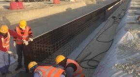
To meet the strength requirements of BS EN 1433, the following has been concluded:
A15 – C250 Loading:
All channel sizes – Steel reinforcing is not required within the channel concrete encasement/surround.
D400 Loading: Channel size 600mm wide requires reinforcement within channel concrete encasement/ surround.
E600 Loading: Channel sizes 400-600mm wide requires reinforcement within channel concrete encasement/surround.


F900 Loading: channel sizes 100-600mm wide requires reinforcement within channel concrete encasement/surround.
The project engineer may decide to install steel reinforcing around all sizes of Gatic Slotdrain where the traffic is heavy and constant, or where ground conditions dictate.
Steel reinforcement installation details are available from Gatic on request for all UltraSlot channels and for chambers formed from concrete on site. These drawings can be supplied to provide an indication of the steel reinforcing for an F900 loading application. Each project has a unique and diverse combination of ground conditions and traffic movements that are beyond the control of Gatic.
As such the Slotdrain product may be required to withstand vertical and horizontal loads outside the scope of the load class and testing criteria specified within BS EN 1433.
We therefore advise that the specifying engineer departs from our standard installation details and adds reinforcement or other applicable construction details where necessary.
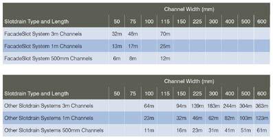
In some projects there may be a requirement to install the slot drain system to follow a given radius, for example around the perimeter of a taxi-way on an airport project, or following the curve of a landscape feature.

Gatic Slotdrain channel units are available in straight lengths of 500mm, 1m or 3m.
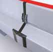
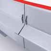
These can be formed using standard units, with each consecutive channel unit positioned at a slight angle in relation to the previous channel. Please refer to the table below for the achievable radius for standard channels in the range. When positioning channel units, the gap formed between channels on the outside edge of the radius should not exceed 5mm.
All gaps between the channel joints, on both sides of the channel, should be sealed with a strong construction tape prior to concreting.
A slot drain channel system will require access units to be placed in strategic locations along the channel run, to provide access into the system for cleaning and maintenance.
The position of access units should be determined by the client and project engineer, taking into account the maintenance equipment that will be used. Specifiers may consider the following:
• Access units should be placed at the start of every channel run.
• Access units should be placed at every corner, or at the point where the channel changes direction.
• 100-350mm Wide Channels: Mid-run access units should be placed every 30-50m.
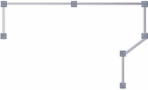
• 400-600mm Wide Channels: Mid-run access units should be placed every 75-100m.
• For short channel runs of 15m long or less, then channel end-caps may be sufficient at the start of the channel run, as cleaning can be carried out from the catch pit end.
Further advice and information is available from Gatic regarding the positioning of access units.
An access unit should always be placed in corner positions
Midpoint access unit (in line)
An access unit can be positioned at the start of channel
These are guidelines only – each project should be individually assessed regarding placement of access units.
Access units should always be placed whenever a channel changes direction
An access unit can be positioned at the start of channel
Catch pit can be used as an access point for cleaning and rodding