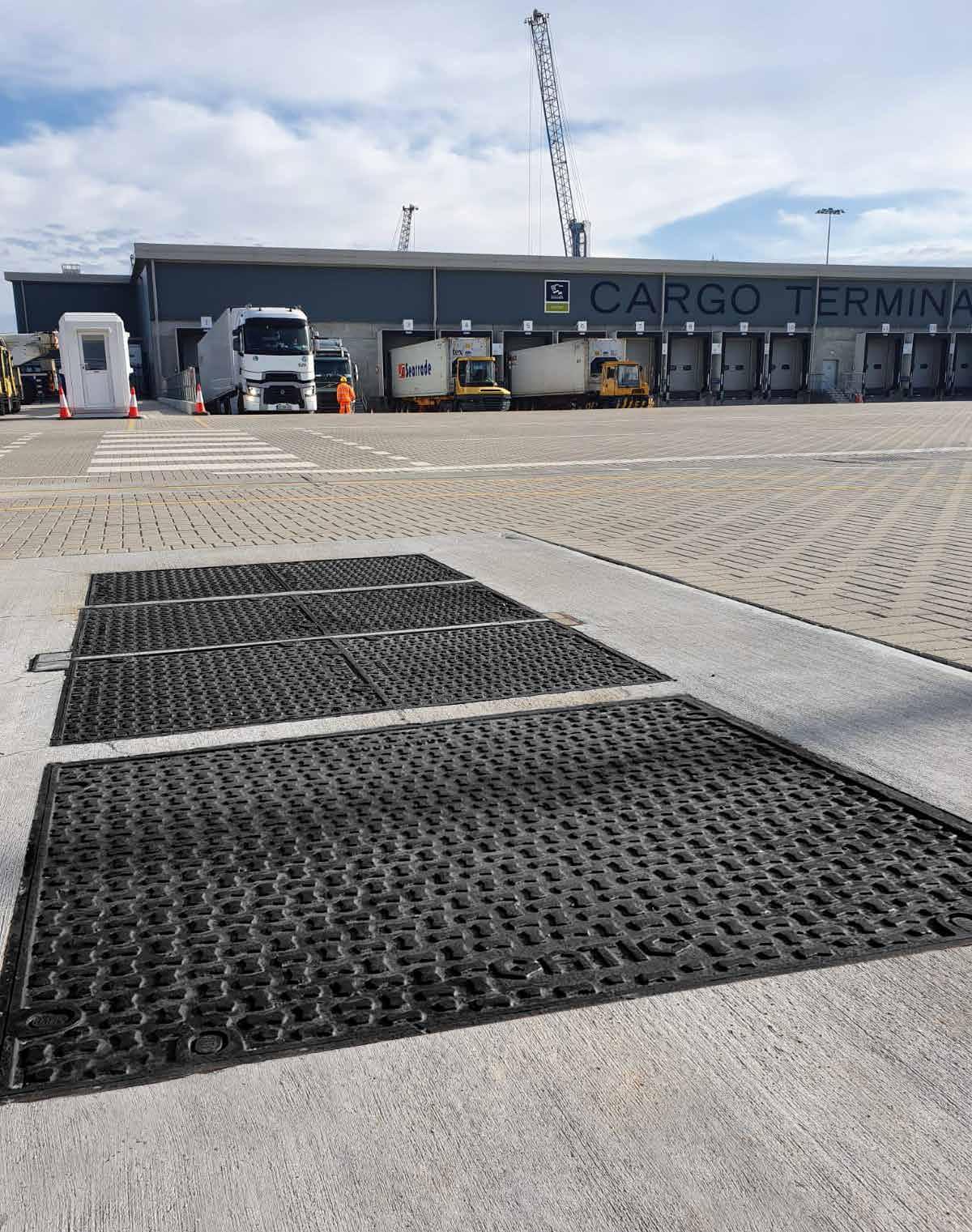
Engineered Access Covers & Drainage Gratings DRAINAGE & ACCESS COVERS March 24 v3

Recommended Viewing Settings For optimum viewing please
Adobe Acrobat. This PDF contains clickable links and bookmarks to allow
to access
information
features
PDF readers. Find out more on
Introduction Loading Group D400 Covers and Frames Gatic - Gas and Air Tight Inspection Covers Introduction 40 Specialised Engineering. Special Advice Single covers and frames 41 An Introduction to Gatic and our Accreditations Duct covers and frames 42 Loading Group Selector Guide 8 Continuous trench covers and frames 43 The Gatic Range of Access Covers 7 Multispan covers and frames Product Features and Benefits 8 Gatic PAVE Loading Group F900 Covers and Frames Loading Group C250 Covers and Frames Introduction 9 Introduction Single covers and frames 10 Single covers and frames Duct covers and frames 16 Duct covers and frames Continuous trench covers and frames 17 Continuous trench covers and frames Multispan covers and frames 20 Multispan covers and frames Assist Lift 23 LFA 24 Loading Group B125 Covers and Frames Introduction Loading Group E600 Covers and Frames Single covers and frames Introduction 26 Duct covers and frames Single covers and frames 27 Continuous trench covers and frames Duct covers and frames 31 Multispan covers and frames Continuous trench covers and frames 33 Multispan covers and frames 34 Additional Access Covers and gratings 35 Installation 37 Lifting Keys 39 2 www.alumascwms.co.uk +44 (0) 1787 475 151 Introduction Specification F900 E600 D400 C250 B125 Additional Covers/Gratings
Contents
use
you
the
faster. Some of these
may not work in other
Page 6.
Introduction About Alumasc Water Management Solutions
Rain to drain solutions that set the standard for urban water management
Alumasc is a UK-based supplier of premium building products. The majority of the group’s business is in the area of sustainable building products which enable customers to manage energy and water use in the built environment.
Alumasc Water Management Solutions provide ‘Rain to Drain’ solutions, that set the standard for urban water management. They include: Skyline Fascias, Soffit & Copings; Alumasc Rainwater Gutters & Downpipes; Harmer Building Drainage; Wade Building Drainage and Gatic Drainage & Engineered Access Covers.
Under the AWMS banner, customers benefit from rainwater and drainage products that capture, retain and control the flow of rainwater in the most effective way inside and outside buildings.
BUILDING DRAINAGE WA DE DRAINAGE & ACCESS COVERS
ARCHITECTURAL ALUMINIUM
3 www.alumascwms.co.uk +44 (0) 1787 475 151 Introduction Specification F900 E600 D400 C250 B125 Additional Covers/Gratings

Gatic’s involvement with gas air-tight inspection covers spans more than 90 YEARS
In fact, one of the earliest covers produced by the company (then known as Dover Engineering) is still in service at a Shell garage in Malta, where it was first installed in 1928.
GATIC
GAS AIR TIGHT INSPECTION COVERS


A challenge in the twenties. Still challenging today.
With a history of installations dating back more than ninety years, Gatic is without doubt the fully proven International Standard for engineered access covers and drainage gratings.
Original 1928 cover still in use
When we were asked to design our first gas and air tight cover for Shell, back in the 20s, it was to a demanding specification. Our success in meeting this specification can be judged by the fact that one of the first covers supplied can still be seen in use at a Shell garage in Malta where it was originally installed.
Continuous development and refinement
Since that first success we have continued to improve and adapt our range of products to suit the ever increasing and diverse demands of travel, industry and commerce, developing ductile iron, machined access covers in a range of surface finishes and load ratings to cope with the harshest and most punishing of environments.
Future challenges
Despite this huge variety, technology never stands still for long and we are never allowed to rest on our laurels. These days more and more traffic is using our roads, carrying heavier loads at higher speeds. Huge numbers of containers pass through our ports daily and ever bigger and heavier aircraft are rolling down the taxiways and across the aprons of the airports we serve.
The challenges may be daunting but we are confident that we will continue to rise to the occasion and supply products to meet or exceed our customers demands.
Introduction Specification F900 E600 D400 C250 B125 Additional Covers/Gratings
Standards & advice
Best products. Best advice. Best results.
At Gatic, we know that our reputation is only as good as the performance of our products. So we do our very best to ensure that the product you buy is the right product for the job and that it is installed correctly in order to be able to do its job successfully. That is why we make a point of supplying all the help and technical support that we can.
Manufacturing standards
It all starts with the manufacturing process. All the basic components for Gatic covers are cast to exacting specifications, developed over time.
The composition of the ductile iron is tightly controlled and the tolerances of the actual casting process are held to fine and demanding limits.
This is because our products will eventually be machined to tight specifications in order to achieve the gas, air-tight and non-rocking fit upon which our reputation is built.
Gatic covers are produced in a wide range of strength ratings to suit any real-life application. When correctly installed, they can be expected to continue to perform as intended for the lifetime of the project, with minimal servicing. Our covers are designed to work effectively in the harshest environments.
Details of the range of load factors to match your requirements can be found on pages 10-11 of this publication. Selecting the appropriate product for your intended application means that you will achieve the service life and performance you need without over specifying, thus ensuring that you get the product you need with the most beneficial ratio of strength to cost. We can help you with this selection process and regard it as a very important part of our service.

Professional advice on your project
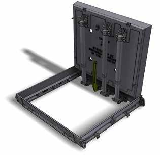
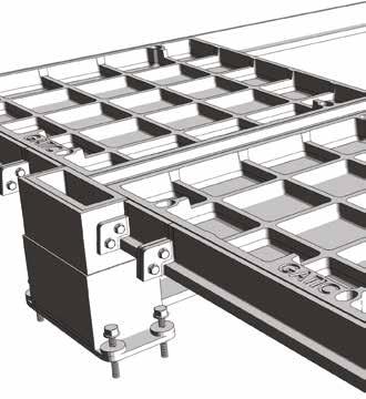
Our design engineers are available to discuss the technical aspects of any project involving Gatic covers, whether large or small. The application of a little expert knowledge often means that what appear to be intractable problems can be overcome with relative ease. You can tap into this expertise either through our website www.gatic.com or by calling Tel: +44 (0)1787 475 151. You will find most of the information you need to narrow down the choice of covers for your particular project within the pages of this publication. To see in detail how Gatic covers are constructed and fitted on site, we suggest you go to the website, where much more information is available.
Expert advice and assistance
If your project throws up some particularly challenging problem which needs an in-depth understanding, please don’t hesitate to get in touch since, in all probability, we have encountered a similar challenge before and, even if this is not the case, our 90-plus years of experience in dealing with these issues are sure to help you reach a satisfactory resolution.
Once these choices have been made you can relax, safe in the knowledge that your covers will be delivered to site in a timely manner.
5 www.alumascwms.co.uk +44 (0) 1787 475 151 Introduction Specification F900 E600 D400 C250 B125 Additional Covers/Gratings
Standards & advice
Pre-delivery assembly
All Gatic products are pre-assembled and quality checked prior to dispatch from our factory.
This process not only assures us that our cover is up to specification and worthy of the Gatic name, but means that our customers can expect it to perform in service to the high standards they have a right to expect and to continue to do so long into the future.
CPDs
We also offer CPD presentations at your premises covering all aspects of design and specification of Gatic Access Covers. Our presentations are accredited by the CPD Certification Service and count towards the continuing personal and professional development of attendees. It’s a factor worth bearing in mind for those individuals seeking professional membership.
Contact gatictech@alumascwms.co.uk for more information or to book your place.
NBS Source
Our technical product information for Alumasc WMS is included in this dedicated library of manufacturers product information contained within NBS Source. NBS Source is a library of manufactures’ product information, written in NBS format and linked to specific clauses within NBS specification software products.
Products listed in NBS Source are directly linked to specific clauses and can be imported instantaneously into a specification. NBS Source contains over 20,000 product specifications and is updated regularly, so designers can be confident that they are always referencing the very latest product information.
Links to specifications for all Gatic products on NBS Source are available on our website.


Our website now contains even more technical information and guidance than before. We have increased our online resources and improved the website design so you can now find all the technical information you need for your projects easily and quickly.
Within each product range, you can explore features and benefits, technical details, graphics, diagrams, and case studies.

Covers and frames – for performance and flexibility
Gatic sets the standard for access covers and frames, offering a combination of matchless quality with tried and tested solutions. The secret lies in the closely machined horizontal and vertical seating faces of the cover and frame components, which, when assembled into a complete unit, provide a cover and frame that is non rocking, gas & air tight.
6 www.alumascwms.co.uk +44 (0) 1787 475 151 Introduction Specification F900 E600 D400 C250 B125 Additional Covers/Gratings
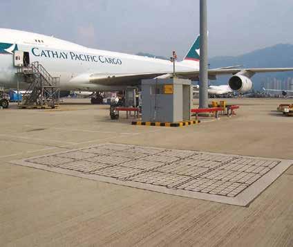
Gatic covers are designed both to protect and give easy access to a diverse range of underground services, examples include:
• Manhole/Pump/Valve/Transformer Chambers
• Pipe and Cable Service Trenches
• Cable Draw Pits
• Lighting Pits
• Fuel and Fire Hydrant Pits
• Machinery/Plant Access Chambers
• Combined Sewer/Overflow Chambers
Typical applications can be found in a diverse range of projects including:
• Airports
• Ports/Docks
• Utilities - Gas/Electricity
• Water - Sewerage Treatment Works/ Water Treatment Works/Pumping Stations
• Power Stations/Sub-Stations
• Commercial and Industrial Applications
• Data Centres
• Tunnels
Cover options
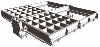
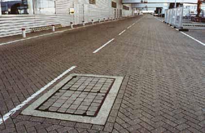
Gatic covers are available in a choice of designs to suit different conditions and requirements for appearance.
Recessed for concrete infill
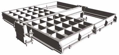
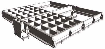
Covers are designed with an arrangement of cross-ribs for infilling with concrete. This provides a very strong and hard wearing surface with an attractive appearance.

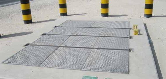
Solid top anti-slip surface
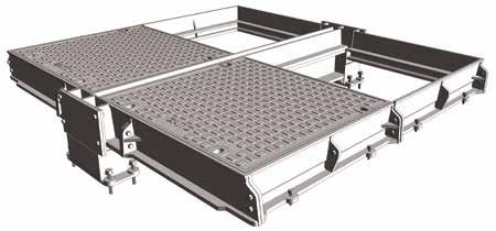
High performance covers that are lighter in weight than those incorporating concrete infill. Solid top covers incorporate a non-slip lozenge pattern on the surface.
NOTE: Covers are also available for Pavior infill.
Quality Assurance
The Gatic Quality Management System has been approved to BS EN ISO 9001
The Gatic Environmental Management System has been approved to ISO 14001


Our products are manufactured from 100 per cent ductile iron, giving high elasticity, which means Gatic covers and frames are highly resistant to physical forces and shock.
Gatic covers comprise ductile iron and structural steel components, all of which are recyclable.
Using this brochure
Gatic covers have been created to suit the widest range of applications and to meet different loading requirements, from relatively light loads (eg, pedestrian areas and residential roads) to the most heavy (eg, airports, dockyards, etc).
BS EN 124: classifies covers according to their place of installation as shown below. Where there is any doubt, the stronger class should be selected.
Data from BS EN 124: (Gully tops and manhole tops for vehicular and pedestrian areas. Design requirements, type testing, marking, quality control)
The covers in our brochure are organised according to the BS EN 124 classifications. Please refer to the Loading Group Selector Guide on pages 10-11.
Loading description BS EN 124 Class Test Load Areas imposing particularly high wheel loads F900 900kN Areas imposing high wheel loads E600 600kN Carriageways of roads (heavy duty) D400 400kN Gully tops in kerbside channels of roads C250 250kN Footways, pedestrian areas, etc B125 125kN
ASSURANCE Approved to BS EN ISO 9001Certificate No. FM 593418 ENVIRONMENTAL ASSURANCE Approved to ISO 14001 Certificate No. EMS 593419 Accreditations 7 www.alumascwms.co.uk +44 (0) 1787 475 151 Introduction Specification F900 E600 D400 C250 B125 Additional Covers/Gratings
QUALITY
Loading group selector guide
The Gatic range of loading groups is organised according to BS EN 124: (Gully tops and manhole tops for vehicular and pedestrian areas. Design requirements, type testing, marking, quality control).
Loading Group F900
35 tonne slow moving wheel load - test load 900kN
Areas imposing particularly high wheel loads:
▪ Airfield pavements
▪ Taxiways
▪ Civil airports
Loading Group E600
20 tonne slow moving wheel load - test load 600kN
Areas imposing high wheel loads:
▪ Some airfield pavements
▪ Dockyards
▪ Other areas where single slow moving wheel loads up to 35 tonne may be encountered

▪ Dockyards
▪ Other areas where single slow moving wheel loads up to 20 tonne may be encountered
Loading Group D400
11.5 tonne wheel load - test load 400kN
▪ Power stations
▪ Carriageways
▪ Hard shoulders
▪ Parking areas for all vehicle types
▪ For high density traffic conditions we recommend the use of a vibration resistant locking system

Loading Group C250
5 tonne wheel load - test load 250kN
▪ Roads for relatively slow moving traffic, ie:
▪ Minor residential
▪ Cul-de-sacs
▪ Pedestrian precincts
▪ Yard
Loading Group B125
3 tonne wheel load - test load 125kN
▪ Footways
▪ Pedestrians areas
▪ Car parks
▪ Driveways
▪ Internal floors

8 www.alumascwms.co.uk +44 (0) 1787 475 151 Introduction Specification F900 E600 D400 C250 B125 Additional Covers/Gratings
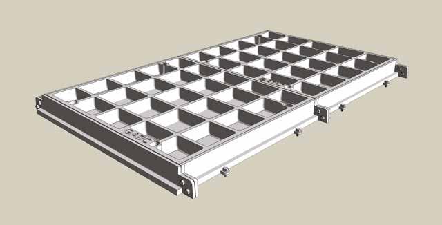
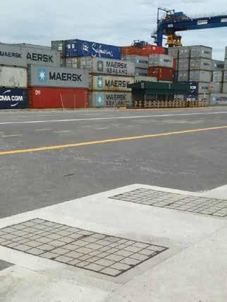
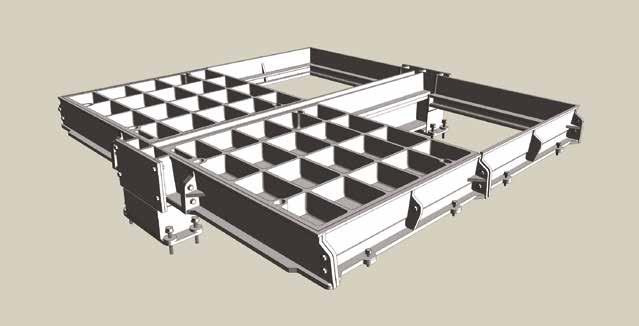
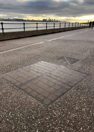
The range of access covers
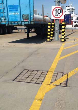
Single Covers and Frames



Duct Covers and Frames



9 www.alumascwms.co.uk +44 (0) 1787 475 151 Introduction Specification F900 E600 D400 C250 B125 Additional Covers/Gratings
Continuous Trench Covers and Frames Multispan Covers and Frames
Features and benefits
Cover types
Covers are recessed for concrete infill paviours or solid top according to specifier preference. Assist lift options for both recessed and solid top cover types are available.
Concrete infill recessed covers
Recessed covers are designed for filling with concrete as specified in BS EN 124 - 45 N/mm 2 for a test cube of 150mm, or a 40N/mm2 for a test cylinder 150mm diameter x 300mm high, using a 10mm down coarse aggregate.
Anti-slip surface covers
Concrete infill covers provide a non-slip surface similar to the surrounding areas. Solid top covers incorporate a lozenge pattern on the surface.
Materials
The components of Gatic covers are manufactured from the following materials:
Ductile iron components to BS EN 1563
Structural steel sections (removable beams) to BS EN 10365.
Fine tolerances
The seating faces of Gatic covers and frames are machined to ensure metal-to-metal contact within 0.25mm tolerance.
Non-rocking
Correctly installed, Gatic covers will be non-rocking and sealed against ingress of road dirt and other detritus.
Gas, Air & Watertight
A film of graphite grease between the contact faces of Gatic units provides a gas and air & water tight seal, and a watertight joint under normal rainwater conditions.
Operator control
Jack screw operating keys locate positively and securely into Gatic covers and are a necessary tool if the inherent cover seal is to be broken effectively and to allow operator maximum control during operation.
Secure and vandal resistant
Covers are designed to prevent tampering and unauthorised removal. Gatic covers cannot be removed without the correct lifting key, so unauthorised removal is virtually impossible. Locking bolts can be fitted to Gatic cover as an additional security feature.
Ventilation
Ventilation can be provided with four 25mm diameter ventilation tubes in recessed covers.
Pressure-tight
Standard single units with locking screws and holding-down bolts are available to withstand upward pressure. Consult our technical department for details.
Easy removal/replacement
The machined underside seating face of Gatic covers allows the sliding out of covers for easy removal or replacement
Vibration resistant
For covers in high density traffic conditions, we recommend the use of a factory-fitted vibration-resistant locking system to the recessed covers.
Note:
• We do not recommend the use of solid top covers in high density traffic locations.
Closed keyways
Gatic cover keyways are closed and fitted with plastic plugs to prevent them from blocking up
Locking/ventilated Watertightness under pressure Locking screw Anchor bolt Locking screw (optional) 25mm diameter ventilation tube Vibration-resistant locking bolt 165 200 180 200 Reinforced ring beam with rebate cast in Rebate to be concrete filled Rebate to be concrete filled Rebate to be concrete filled Locking/ventilated Watertightness under pressure Locking screw Anchor bolt Locking screw (optional) 25mm diameter ventilation tube Vibration-resistant locking bolt 165 200 180 Reinforced ring beam with rebate cast in Rebate to be concrete filled Rebate to be concrete filled Rebate to be concrete filled Locking/ventilated Watertightness under pressure Vibration resistant Locking screw Anchor bolt Locking screw (optional) 25mm diameter ventilation tube Vibration-resistant locking bolt 165 200 180 200 Reinforced ring beam with rebate cast in Rebate to be concrete filled Rebate to be concrete filled Rebate to be concrete filled
10 www.alumascwms.co.uk +44 (0) 1787 475 151 Introduction Specification F900 E600 D400 C250 B125 Additional Covers/Gratings
Features and benefits
Loadings
All Gatic covers will withstand test load and maximum permanent set criteria specified in BS EN 124 for each loading category. Covers are load tested in their as service condition.
Rigidity
The robust and rigid design of Gatic’s frames, closely toleranced covers and frames creates a rigid composite structure.
Secure support
The clear opening width between supporting frames are at least 10mm greater than the pit/chamber design to allow for minor deviations in pit construction dimensions.
Beam wallbox
Supporting beams in Gatic Multispan units are easily removed with appropriate lifting equipment for access to the total chamber area. Beam wallboxes do not project into the chamber opening.
Finishes
Units are coated with a black bituminous solution that acts as a temporary protection during transit. Removable supporting steelwork is galvanised to BS EN ISO 1461. For special applications, cover & frame components can be galvanised to BS-EN ISO 1461.
Installation
Consignments of Gatic units are accompanied by comprehensive installation instructions.
Levelling bolts
All frame bars and wallboxes are fitted with bolts to assist in the levelling of the unit during installation.
Security grids
Hinged lift-out galvanised steel security grids (with padlock facility if required) can be incorporated into Gatic units.
Environmental commitment
Responsibility towards the environment is our primary concern. Our customers often now demand products that are made from recycled and recyclable materials, supplied by companies with robust environmental policies to reduce the environmental impact of their projects for future generations.
To meet these requirements we have an integrated Quality (BS EN ISO 9001) and Environmental (BS EN ISO 14001) Management System which encompasses the design, manufacture and management systems within the company and ensures our commitment to continuous environmental improvements regarding the manufacture and design of all our products in the following ways:
Minimise environmental impact
• Commit organisational resources to energy management
Reduce energy costs
Give high priority to energy efficient investments
Consider life cycle energy costs for all new projects
Minimise CO2 emissions year on year
Use energy from sustainable resources wherever possible
To achieve these goals we have put in place the necessary systems and controls to meet demanding environmental targets and to make sure that these are maintained for the future benefit of the environment and our customers alike.
Gatic services
Gatic offers a full support service to specifiers and contractors, including Computer Aided Design. AutoCAD compatible details of all Gatic products are available. Please consult our technical department for assistance. In view of our commitment to product improvement, we reserve the right to alter designs without notice. Design changes will not adversely affect the performance or loading capability of our products.


QUALITY ASSURANCE The Gatic Quality Management System has been approved to BS EN ISO 9001 Certificate No. FM 593418 ENVIRONMENTAL ASSURANCE The Gatic Environmental Management System has been approved to ISO 14001 Certificate No. EMS 593419
11 www.alumascwms.co.uk +44 (0) 1787 475 151 Introduction Specification F900 E600 D400 C250 B125 Additional Covers/Gratings

F900
Introduction Specification F900 E600 D400 C250 B125 Additional Covers/Gratings
Loading group F900 introduction
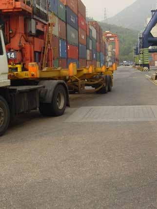
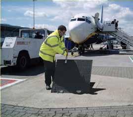
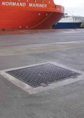
Areas of exceptionally high wheel loads, aircraft hard-standings, taxiways at civil airports, container ports and dockyards
35 tonne slow moving wheel load, test load 900kN – Suitable for:
• Aircraft hard-standings and taxiways at civil airports
Container ports and dockyards where individual wheel loadings of up to 35 tonnes may be encountered
F900 assemblies are available with a choice of cover designs – recessed or solid top.


Solid top
Solid top cover types are lighter in weight than recessed covers, and feature an anti-slip surface. Solid top covers are denoted by the code Type RSF depicted in section on the following pages.

Product Ranges


Recessed for concrete infill Recessed covers are available in a choice of designs designated by a ‘Type’ reference. F900 recessed covers are available as Type DLF, DM ,RRF, DM/F. Section drawings of the different recessed cover types are shown on the following pages.
To prevent movement of covers in high traffic conditions, we recommend the use of a factory fitted vibrationresistant locking system. Can be fitted to recessed covers only. See page 14.


Gatic Ty pe S SA side hing ed c overs a re a ll assist lift to gi ve complete access to the chambe below. d-alon e As sistLi ft c overs a re ava ilable y of c onfigurati on s. d- to p As sistLi ft c over –Tw o- pa rt s olid -top c over – Ty pe S SA Th es e are fi tted w it h a re mova bl e ce ntra l suppor t ba r. over –Ty pical sections of soli d- to p cover – Ty pe S SA RE BATE O BE ILLED
Single covers and frames
Duct covers and frames Assist Lift
Continuous trench covers and frames
Multispan covers and frames
LFA
13 www.alumascwms.co.uk +44 (0) 1787 475 151 Introduction Specification F900 E600 D400 C250 B125 Additional Covers/Gratings
Single recessed covers and frames
Areas of exceptionally high wheel loads, aircraft hard-standings, taxiways at civil airports, container ports and dockyards

● Covers recessed for concrete infill
● Cover type: DLF, DM, DM/F, RRF
To specify state:
1. Loading group
2. Pit clear opening size length (L) x span (S)
3. Cover type

Cover Types
Pit clear opening sizes L x S Cover type Overall frame size length x width x depth Suggested rebate size length x width x depth 750 x 300 DLF 900 x 540 x 75 1050 x 600 x 100 600 x 450 RRF 750 x 690 x 100 1000 x 850 x 125 750 x 450 RRF 900 x 690 x 100 1150 x 850 x 125 600 x 600 RRF 750 x 840 x 100 1000 x 1000 x 125 750 x 600 RRF 900 x 840 x 100 1150 x 1000 x 125 900 x 600 RRF 1050 x 840 x 100 1300 x 1000 x 125 750 x 750 RRF 900 x 990 x 100 1150 x 1150 x 125 900 x 750 RRF 1050 x 990 x 100 1300 x 1150 x 125 900 x 900 RRF 1120 x 1140 x 100 1300 x 1300 x 125 600 x 1050 DM 820 x 1270 x 140 1000 x 1450 x 165 750 x 1050 DM 970 x 1270 x 140 1150 x 1450 x 165 1000 x 1050 DM 1220 x 1270 x 140 1400 x 1450 x 165 600 x 1200 DM 820 x 1420 x 140 1000 x 1600 x 165 750 x 1200 DM 970 x 1420 x 140 1150 x 1600 x 165 600 x 1500 DM/F 820 x 1720 x 140 1000 x 1900 x 165 750 x 1500 DM/F 970 x 1720 x 140 1150 x 1900 x 165
P an of recessed s ngle cover Plan of recessed duct cover Section A - A Check d b Da e S P o ect T t e D g N b DO NOT SCALE Po on C o e Do er Ken CT17 0UF Eng a d T ph +4 0 13 4 203545 F +44 0 13 4 215001 E M @g W b g A d ALUMASC L M TED Th s d aw ng and any n orma on or descr p ve ma er se ou he eon a e con dent a and the copy gh o GAT C and are no o be d sc osed oaned cop ed or used fo manufac u ng or ende ng o fo any o he purpose w thou perm ss on © 2017 Des gners nc ud ng bu no m ed o Eng neers and Arch tec s mus sa sfy hemse ves n espec o the adequacy o the des gn prov ded by GAT C t s he Des gne s respons b y o ensure ha the da a has been co rect y n erpre ed GAT C accepts no ab ty or nadequa e or naccura e des gns based on m ed or a se nfo mat on supp ed by he Des gne o m s nte p e a on o he da a supp ed Fo he avo dance o doub des gns prov ded by GAT C p o o an orde be ng p aced a e or ustra ve pu poses on y and shou d not be e ed upon save or a he Des gner s own sk D aw ngs ssued by GAT C n espec of an order af er ha orde has been p aced sha be fit or he purpose o wh ch t was c ea ed y R R TYPE COVERS R TYPE COVERS AND FRAME PLAN NCLUDING SECTION DETA LS - FOR E600 AND F900 OF BROUCHURE EG/4587 A P S 27 06/2019 N T S P M N A a o A1 Rev Revis on Da e Sig A FIRST ISSUE 27/06/2019 P S Length (L) Length (L) S p a n ( S ) S p a n ( S ) Sugested rebate ine Sugested rebate ine 1 0 0 1 2 5 S P t c ear open ng span 200 110 10 Cover & rebates to be f led with 45 cube or 40 cy inder concrete dur ng insta lat on us ng 10mm coarse aggregate 7 5 Ful he ght webs Type DM/F Type DLF Type RRF Suggested rebate line Plan of recessed cover
75 57 100 110 10 150 S Pit clear opening span Full height webs Cover & rebates to be filled with 45 cube or 40 cylinder concrete during installation using 100 coard aggregate 140 84 165 100 10 200 S Pit clear opening span Full height webs Cover & rebates to be filled with 45 cube or 40 cylinder concrete during installation using 100 coard aggregate Full height webs Pit clear opening span Section A-A 200 125 10 110 100 75 S Cover & rebates to be filled with 45 cube or 40 cylinder concrete during installation using 100 coard aggregate 14 www.alumascwms.co.uk +44 (0) 1787 475 151 Introduction Specification F900 E600 D400 C250 B125 Additional Covers/Gratings
Single solid
Areas of exceptionally high wheel loads, aircraft hard-standings, taxiways at civil airports, container ports and dockyards

• Covers with solid top
Cover type RSF
To specify state:
1. Loading group
2. Pit clear opening size length (L) x span (S)
3. Cover type

Cover Types
Pit clear opening sizes L x S Cover type Overall frame size length x width x depth Suggested rebate size length x width x depth 600 x 600 RSF 750 x 840 x 100 1000 x 1000 x 125 750 x 600 RSF 900 x 840 x 100 1150 x 1000 x 125 900 x 600 RSF 1050 x 840 x 100 1300 x 1000 x 125 700 x 700 RSF 850 x 940 x 100 1100 x 1100 x 125 750 x 750 RSF 900 x 990 x 100 1150 x 1150 x 125 900 x 750 RSF 1050 x 990 x 100 1300 x 1150 x 125 900 x 900 RSF 1120 x 1140 x 100 1300 x 1300 x 125 1000 x 1000 RSF 1220 x 1240 x 100 1400 x 1400 x 125 Plan of solid top single cover Plan of solid top duct cover Section A - A Ch k d by D Sca e Pro ec Tit e Draw ng Numbe DO NOT SCALE P C D K CT17 0UF Eng and T ph 44 0) 1304 203545 Fax +44 0 1304 215001 E Ma n o@ga c com Web www ga c com A d v s on o ALUMASC L M TED Th s d aw ng and any nformat on or descr pt ve mat e set out hereon are confidentia and he copyr ght of GAT C and are not to be d sc osed oaned cop ed or used fo manufactur ng or tende ng or fo any o her pu pose w thout perm ss on © 2017 Des gne s nc ud ng but not m ed to Eng nee s and Architects mus sa s y hemselves n respect o he adequacy of the des gn prov ded by GAT C It s the Designer s responsibil y o ensure that he da a has been correc y n erp e ed GAT C accepts no l abil y or nadequate or inaccura e designs based on m ted o a se info mat on supp ed by the Designer or m s n e pre a on of he data supp ed For the avo dance of doub des gns prov ded by GAT C p or to an o der be ng p aced are or us rat ve purposes only and shou d not be re ed upon save or a the Des gner s own r sk Draw ngs ssued by GAT C n respect of an o der a ter that order has been p aced sha be t or the purpose fo wh ch t was c ea ed D a by Rev R TYPE COVERS R TYPE COVERS AND FRAME PLAN INCLUDING SECTION DETAILS - FOR E600 AND F900 OF BROUCHURE EG/4590 A P S 27/06/2019 N T S P M N A Part No A1 Rev Rev sion Date Sig A FIRST ISSUE 27/06/2019 P S Length (L) Length (L) S p a n ( S ) S p a n ( S ) Sugested rebate ine Sugested rebate line 1 2 5 S P t clear opening span 200 Rebates to be fi led with 45 cube or 40 cylinder concrete during nsta lation using 10mm coarse aggregate Solid tops covers 1 0 0 110 10 Suggested rebate line Plan of solid cover
top
covers and frames
Type RSF Cover & rebates to be filled with 45 cube or 40 cylinder concrete during installation using 100 coard aggregate Solid top covers 125 200 110 10 S 100 Pit clear opening span Section A-A 15 www.alumascwms.co.uk +44 (0) 1787 475 151 Introduction Specification F900 E600 D400 C250 B125 Additional Covers/Gratings
Recessed duct covers and frames
Areas of exceptionally high wheel loads, aircraft hard-standings, taxiways at civil airports, container ports and dockyards
• Covers recessed for concrete infill
• Cover type DLF, DM/F, RRF
To specify state:
1. Loading group
2. Pit clear opening size length (L) x span (S)
3. Cover type
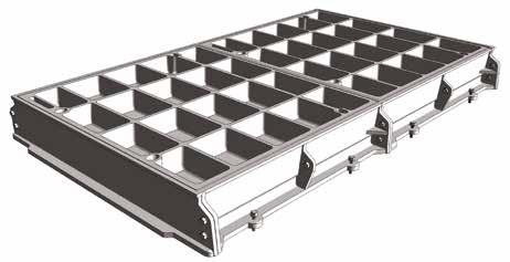
300
1200
1500
Pit clear opening span (S) Cover type Standard pit clear opening length (L) 1300 1450 1600 1750 1900 2000 2150 2300 2450 2600 2700 2750 300 DLF * * 2 * * * * * 3 * * * 450 RRF 2 2 2 * * 3 3 3 3 * 4 * 600 RRF 2 2 2 2 2 3 3 3 3 3 4 3 750 RRF 2 2 2 2 2 3 3 3 3 3 4 3 900 RRF 2 2 2 2 2 3 3 3 3 3 4 3 1050 DM/F 2 2 2 * * 3 3 3 3 * 4 * 1200 DM/F 2 2 2 * * 3 3 3 3 * 4 * 1500 DM/F 2 2 2 * * 3 3 3 3 * 4 * Pit clear opening span (S) Cover type Standard pit clear opening length (L) 2850 2900 3000 3150 3300 3400 3550 3700 3850 3900 4000 4150 300 DLF * * * * 4 * * * * * * 5 450 RRF 4 * 4 4 4 5 5 5 5 * 5 5 600 RRF 4 3 4 4 4 5 5 5 5 4 5 5 750 RRF 4 3 4 4 4 5 5 5 5 4 5 5 900 RRF 4 3 4 4 4 5 5 5 5 4 5 5 1050 DM/F 4 * 4 4 4 5 5 5 5 * 5 5 1200 DM/F 4 * 4 4 4 5 5 5 5 * 5 5 1500 DM/F 4 * 4 4 4 5 5 5 5 * 5 5 Pit clear opening sizes Cover type Suggested rebate size length x width x depth
DLF (L + 300) x 600 x 100
RRF (L + 400) x 850 x 125
RRF (L + 400) x 1000 x 125 750 RRF (L + 400) x 1150 x 125
RRF (L + 400) x 1300 x 125
DM/F (L + 400) x 1450 x 165
450
600
900
1050
DM/F (L + 400) x 1600 x 165
DM/F (L + 400) x 1900 x 165
Plan of recessed sin Plan of recessed duct cover Section A - A Che ked b Da e S Pro e T e DO NOT SCA Th s draw ng and any n o ma on o desc pt ve ma te se ou hereon are conf den a and he copyr gh of GAT C and are no o be d sc osed oaned cop ed or used or manu actu ng o tender ng or or any other pu pose w hou perm ss on © 2017 Des gne s nc ud ng bu no l m ed to Eng nee s and A ch ects must sat s y hemse ves n respect of he adequacy of he des gn prov ded by GAT C s the Des gner s respons b y o ensu e hat he da a has been cor ec y nte p eted GAT C accep s no ab y o nadequate or naccu ate des gns based on m ed o fa se n orma on supp ed by the Des gner or m s n erpre at on o the data supp ed Fo the avo dance o doubt des gns p ov ded by GATIC pr o o an o der be ng p aced are o us at ve purposes on y and shou d no be re ed upon save o a he Des gne s own r sk Draw ngs ssued by GAT C n espec o an o de a er ha o der has been p aced sha be o the purpose for wh ch was created N P S 27/06 2019 N T S P M N A a o A1 Rev A F RST ISS Length (L) Length (L) S p a n ( S ) S p a n ( S ) Sugested rebate l ne 1 0 0 1 2 5 S P t clear opening span 200 110 10 Cover & rebates to be f l ed w th 45 cube or 40 cylinder concrete dur ng installation using 10mm coarse aggregate 7 5 Fu l height webs * Indicates standard sizes not available. The number shown indicates the quantity of cover parts. Other spans of covers are available upon request. Contact gatictech@alumascwms.co.uk for further information. Suggested rebate line Plan of recessed cover
Type DM/F Type DLF Type RRF Cover Types 75 57 100 110 10 150 S Pit clear opening span Full height webs Cover & rebates to be filled with 45 cube or 40 cylinder concrete during installation using 100 coard aggregate 140 84 165 100 10 200 S Pit clear opening span Full height webs Cover & rebates to be filled with 45 cube or 40 cylinder concrete during installation using 100 coard aggregate Full height webs Pit clear opening span Section A-A 200 125 10 110 100 75 S Cover & rebates to be filled with 45 cube or 40 cylinder concrete during installation using 100 coard aggregate 16 www.alumascwms.co.uk +44 (0) 1787 475 151 Introduction Specification F900 E600 D400 C250 B125 Additional Covers/Gratings

• Covers with solid top
• Cover type RSF
To specify state:
1. Loading group
2. Pit clear opening size length (L) x span (S)
3. Cover type

*
for further information.
For high density traffic conditions refer to page 14.
Pit clear opening span (S) Cover type Standard pit clear opening length (L) 1300 1450 1500 1600 1750 1900 2000 2150 2300 2450 2600 2700 2750 600 RSF 2 2 * 2 2 2 3 3 3 3 3 4 3 700 RSF * * 2 * * * * * 3 * * * * 750 RSF 2 2 * 2 2 2 3 3 3 3 3 4 3 900 RSF 2 2 * 2 2 2 3 3 3 3 3 4 3 Pit clear opening span (S) Cover type Standard pit clear opening length (L) 2850 2900 3000 3100 3150 3300 3400 3550 3700 3850 3900 4000 4150 600 RSF 4 3 4 * 4 4 5 5 5 5 4 5 5 700 RSF * * * 4 * * * * * * 5 * * 750 RSF 4 3 4 * 4 4 5 5 5 5 4 5 5 900 RSF 4 3 4 * 4 4 5 5 5 5 4 5 5 Pit clear opening sizes Cover type Suggested rebate size length x width x depth 600 RSF (L + 400) x 1000 x 125 700 RSF (L + 400) x 1100 x 125 750 RSF (L + 400) x 1150 x 125 900 RSF (L + 400) x 1300 x 125
Indicates standard sizes
number
quantity of cover parts.
spans of covers
gatictech@alumascwms.co.uk
not available. The
shown indicates the
Other
are available upon request. Contact
Plan of solid top Plan of solid top duct cover Section A - A Ch k d by D Sca e P T DO NOT SC This drawing and any n orma on or descr p ve ma ter se out hereon a e con den a and the copy ght o GATIC and a e not o be d sc osed oaned cop ed o used for manufac ur ng o ender ng or for any o he purpose w thout permiss on © 2017 Des gners inc ud ng bu not mited to Eng neers and Arch tec s must sat sfy hemse ves n respec of the adequacy of he design p ovided by GATIC t s he Des gne s respons b ty to ensure ha he da a has been correc y n e pre ed GATIC accep s no ab ty o nadequa e or naccurate des gns based on lim ed or false nforma ion supp ed by he Des gne o m sinterpreta on o he da a supp ed For the avo dance o doubt des gns p ovided by GATIC pr or to an order be ng p aced a e fo ust ative purposes on y and shou d not be relied upon save fo at the Designer s own risk Draw ngs ssued by GATIC n respect o an orde af er ha o der has been p aced sha be f or he purpose for wh ch was crea ed Drawn b P S 27 06/2019 N T S P M N/ Pa No A1 Rev A FIRST Length ( Length (L) S p a n ( S ) S p a n ( S ) Sugested rebate ine 1 2 5 S Pit clear open ng span 200 Rebates to be f lled w th 45 cube or 40 cy inder concrete during installation using 10mm coarse aggregate So id tops covers 1 0 0 110 10 Suggested rebate line Plan of solid cover Solid top duct covers and frames
Types Type RSF Cover & rebates to be filled with 45 cube or 40 cylinder concrete during installation using 100 coard aggregate Solid top covers 125 200 110 10 S 100 Pit clear opening span Section A-A 17 www.alumascwms.co.uk +44 (0) 1787 475 151 Introduction Specification F900 E600 D400 C250 B125 Additional Covers/Gratings
Cover
Areas of exceptionally high wheel loads, aircraft hard-standings, taxiways at civil airports, container ports and dockyards

• Covers recessed for concrete infill
• Cover types: DLF, DM/F, RRF
To specify state:
1. Loading group
2. Cover type
3. Supply layout drawing of trenches
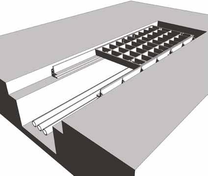
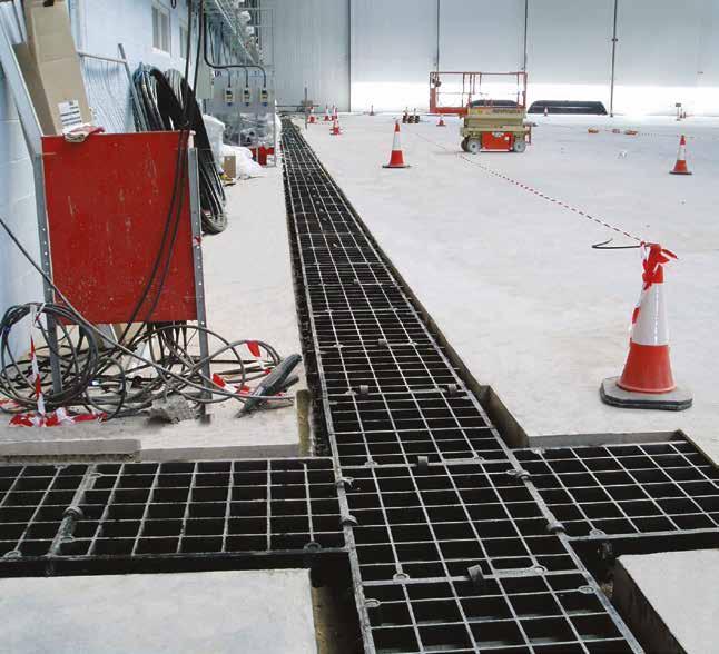
Gatic covers can be formed to make continuous trenches or layouts providing total access to services below. Construction drawings are required so that Gatic cover layout drawings can be prepared.
Pit clear opening span Cover type 300 DLF 450 RRF 600 RRF 750 RRF 900 RRF 1050 DM/F 1200 DM/F 1500 DM/F Continuous recessed cover Other spans of covers are available upon request. Contact gatictech@alumascwms.co.uk for further information.
Continuous recessed trench covers and frames Type DM/F Type DLF Type RRF Cover Types 75 57 100 110 10 150 S Pit clear opening span Full height webs Cover & rebates to be filled with 45 cube or 40 cylinder concrete during installation using 100 coard aggregate 140 84 165 100 10 200 S Pit clear opening span Full height webs Cover & rebates to be filled with 45 cube or 40 cylinder concrete during installation using 100 coard aggregate Full height webs Pit clear opening span Section A-A 200 125 10 110 100 75 S Cover & rebates to be filled with 45 cube or 40 cylinder concrete during installation using 100 coard aggregate 18 www.alumascwms.co.uk +44 (0) 1787 475 151 Introduction Specification F900 E600 D400 C250 B125 Additional Covers/Gratings
Continuous solid top trench covers and frames
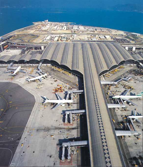
Areas of exceptionally high wheel loads, aircraft hard-standings, taxiways at civil airports, container ports and dockyards
• Covers with solid top
• Cover types: RSF
To specify state:
1. Loading group
2. Cover type
3. Supply layout drawing of trenches


Standard Solid top covers are supplied in straight runs. Junctions and splays can be achieved by the inclusion of localised recessed covers. Refer to our technical department for more information.
For high density traffic conditions refer to page 14.
Cover Types
Pit clear opening span Cover type 600 RSF 700 RSF 750 RSF 900 RSF Continuous
Note: Solid top covers can only be supplied in continuous straight runs
solid top cover
Type RSF Cover & rebates to be filled with 45 cube or 40 cylinder concrete during installation using 100 coard aggregate Solid top covers 125 200 110 10 S 100 Pit clear opening span Section A-A 19 www.alumascwms.co.uk +44 (0) 1787 475 151 Introduction Specification F900 E600 D400 C250 B125 Additional Covers/Gratings
Multispan covers and frames
Areas of exceptionally high wheel loads, aircraft hard-standings, taxiways at civil airports, container ports and dockyards
Specification
Below is a sample specification information and notes for Multispan recessed covers and frames.
For more details on features and benefits of Gatic covers.
Loading group Gatic F900
35 tonne wheel load – test load 900 kN.
Materials
Ductile iron components to BS EN 1563
Structural steel removable beams to BS EN 10365.
Finishes
Units coated with black bituminous solution for protection during transit. Galvanised alternative available. Removable supporting steelwork galvanised to BS EN ISO 1461.
Infill and surround concrete by customer
Concrete strength, using 10mm coarse aggregate, to be: 45N/mm2 for a test cube of 150mm or 40N/mm2 for a test cylinder of 150mm diameter x 300mm high.
Installation
In accordance with instructions supplied by Gatic

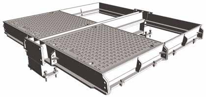
To specify use size and description format as follows:
Gatic Multispan Recessed covers and frames Cover type RRF recessed Multiple access covers recessed for concrete infill with removable beams.
.... in no. .... (length) x .... (span) mm pit clear opening multi span cover and frame.
Gatic Type RRF Ductile Iron Recessed Cover in .... parts complete with .... in no. .... x .... mm galvanised removable support beam spanning the .... (length) mm way.
Suitable for Loading Group F900 – 35 Tonnes Wheel Load (pneumatic tyre).
Gatic Multispan Solid Top covers and frames Cover type RSF solid top Multiple solid top access covers with removable beams.
.... in no. .... (length) x .... (span) mm pit clear opening multi span cover and frame.
Gatic Type RSF Ductile Iron Solid Top Cover in .... parts complete with .... in no. .... x .... mm galvanised removable support beam spanning the .... (length) mm way.
Suitable for Loading Group F900 – 35 Tonnes Wheel Load (pneumatic tyre).
Standard pit clear opening sizes are shown on p25
Beam sizes and other dimensions are shown on p26 - p27
For high density traffic conditions, refer to page 14.
Type RRF recessed
Type RSF solid top
20 www.alumascwms.co.uk +44 (0) 1787 475 151 Introduction Specification F900 E600 D400 C250 B125 Additional Covers/Gratings
Product Selection
Refer to the table to identify which cover and beam configuration you require against pit clear opening length (L) and pit clear opening span (S). All dimensions are in millimetres.
Note: All dimensions shown in red are made up using 700 x 700 solid top covers. Not compatible with other lengths
1380 1530 1580 1680 1830 1980 2160 2310 2460 2460 2610 2760 2910 3060 3240 3090 2940 3340 3390 3540 3690 3840 3990 4140 690 840 840 990 990 690 690 840 790 840 990 990 840 990 840 840 990 990 990 690 690 790 790 840 840 990 780 930 780 880 1080 930 1080 780 1080 930 930 930 930 1080 690 690 840 790 840 930 840 840 990 990 780 1080 930 930 930 930 1080 840 840 780 780 690 690 780 780 690 990 790 880 880 790 690 840 840 990 840 1300 1450 1500 1600 1750 2000 2150 2300 2300 2450 3000 2850 2700 3100 3150 3300 3450 3600 3750 3900 Pit clear opening length (L) mm Beam centres mm Pit clear opening span (S) mm 4 parts 3 beams 3 parts 2 beams 2 parts 1 beam 2 parts 3 parts 4 parts AB CD E 2600 2750 2900 6 part (2x3) recessed multispan cover with 2 removable support beams 9 part (3x3) recessed multispan cover with 2 removable support beams 12 part (4x3) recessed multispan cover with 2 removable support beams 8 part (2x4) recessed multispan cover with 3 removable support beams 12 part (3x4) recessed multispan cover with 3 removable support beams 16 part (4x4) recessed multispan cover with 3 removable support beams L A S B L A S B L A S B L A S B C L A S B C L A C S B L A S B C D L A S B C D L A C D S B 4020 3870 3720 4170 4220 4320 4470 4620 4770 4920 5070 5220 690 790 840 840 990 990 990 930 880 930 930 930 930 1080 930 880 930 1080 930 1080 930 930 840 780 780 780 690 780 930 780 690 780 780 780 880 930 930 930 930 990 1080 1080 1080 1080 690 840 690 690 790 840 930 780 930 840 840 840 990 990 990 990 5 parts 4 beams
part (2x5) recessed multispan cover with 4 removable support beams
part
recessed
cover with 4 removable support beams
part
cover with 4 removable support beams L A S B C D L A S B C D L A C D E E E S B 4 part (2x2) recessed multispan cover with 1 removable support beam 6 part (3x2) recessed multispan cover with 1 removable support beam 8 part (4x2) recessed multispan cover with 1 removable support beam 1900
10
15
(3x5)
multispan
20
(4x5) recessed multispan
Note: For other pit clear opening sizes please refer to our technical department 4 part (2x2) multispan cover with 1 removable support beam 6 part (2x3) multispan cover with 2 removable support beam
part (2x4) multispan cover with 3 removable support beam 10 part (2x5) multispan cover with 4 removable support beam
part (3x2) multispan cover with 1 removable support beam
part (3x3) multispan cover with 2 removable support beam
part (3x4) multispan cover with 3 removable support beam
part (3x5) multispan cover with 4 removable support beam
part (4x2) multispan cover with 1 removable support beam
part (4x3) multispan cover with 2 removable support beam
part (4x4) multispan cover with 3 removable support beam 20 part (4x5) multispan cover with 4 removable support beam
covers and frames 21 www.alumascwms.co.uk +44 (0) 1787 475 151 Introduction Specification F900 E600 D400 C250 B125 Additional Covers/Gratings
8
6
9
12
15
8
12
16
Multispan
Multispan covers and frames
Areas of exceptionally high wheel loads, aircraft hard-standings, taxiways at civil airports, container ports and dockyards
The
Section
Plan showing recessed and solid top cover options
Section A - A
B - B Section C - C Section D - D A A B B C C D D Checked by Da e Sca e DO NOT S This drawing and any nformation or descriptive matter set out hereon are confidential and the copyright of GAT C and are not to be disclosed loaned copied or used for manufactur ng or tendering or for any other purpose w thout permiss on © 2017 Des gners, ncluding but not imited to, Engineers and Arch tects, must satisfy themse ves in respect of the adequacy of the design provided by GATIC It is the Des gner s respons b l ty to ensure that the data has been correctly nterpreted GATIC accepts no iabi ity for nadequate or naccurate designs based on l mited or fa se information supplied by the Designer or mis nterpretat on of the data supp ied For the avoidance of doubt des gns prov ded by GATIC prior to an order being p aced are for l ustrat ve purposes only and should not be re ied upon save for at the Designer s own r sk Draw ngs ssued by GATIC in respect of an order after that order has been p aced sha l be f t for the purpose for wh ch it was created Drawn by P S 27/06/2019 N T S P M N Part No A1 Rev A FIRST X W 1 2 5 145 20 Y L Pit clear opening length Y 1 2 5 DIRECTION FOR SLIDING OUT COVER Removable support beam (supplied by Gatic) Recessed cover type RRF So id top cover type RSF Suggested rebate for beam wallbox Suggested rebate for end frame 125 100 B A X 4 9 0 S P t c e a r o p e n n g s p a n 2 0 0 1 0 1 1 0 85 Suggested rebate for side frame X W D RECTION Re beam 145 20 Y Pit c 1 2 5 1 0 0 10 110 200 B Cover & rebates to be filled with 45 cube or 40 cy concrete dur ng installation using 10mm coarse a F Suggested rebate for beam wallbox Suggested rebate for side frame Suggested rebate for beam wallbox Recessed cover type RRF Solid top cover type RSF A B Plan showing recessed and solid top cover options
A - A
B - B Sectio Section A A B B C C D D eon are confidential and the copyright of GATIC, and are not to be disclosed, loaned, copied or used for manufacturing or tendering or for any other purpose without perm must satisfy themselves in respect of the adequacy of the design provided by GATIC It is the Designer's responsibility to ensure that the data has been correctly interprete limited or false information supplied by the Designer or misinterpretation of the data supplied For the avoidance of doubt designs provided by GATIC prior to an order b e for at the Designer s own risk Drawings issued b e fit for the purpose for which it was created X W 1 2 5 145 20 Y L Pit clear opening length Y 1 2 5 D Removable support beam (supplied by Gatic) Recessed cover type R e RSF Suggested rebate for beam wallbox Suggested rebate for end frame 125 100 B A X 4 9 0 S P i t c l e a r o p e n i n g s p a n 2 0 0 1 0 1 1 0 85 Suggested rebate for side frame X W 1 2 5 1 0 0 Cover & rebates to concrete during ins Suggested rebate for side frame Sugge reba beam wa Recessed cover type RRF Solid top cover type RSF A B
Covers recessed for concrete infill or solid top
Cover types: RRF (recessed) RSF (solid top)
Section
Section
•
•
details
sections
a typical recessed/solid top unit. Type RSF solid top
RRF recessed Plan showing recessed and solid top cover options Section A - A Section B - B Section C - C Section D - D A A B B C C D D Checked Date Sca e D Th s draw ng and any information or descript ve matter set out hereon are conf dent al and the copyr ght of GATIC and are not to be d sclosed loaned copied or used for manufacturing or tendering or for any other purpose w thout permission © 2017 Designers, including but not lim ted to, Engineers and Architects, must sat sfy themse ves in respect of the adequacy of the design provided by GATIC t is the Designer s respons bility to ensure that the data has been correctly interpreted GAT C accepts no liab l ty for inadequate or inaccurate designs based on l mited or false information suppl ed by the Des gner or misinterpretat on of the data supp ied For the avoidance of doubt, designs provided by GATIC pr or to an order be ng p aced are for illustrat ve purposes only and should not be rel ed upon save for at the Des gner s own r sk Drawings issued by GATIC in respect of an order after that order has been placed shal be fit for the purpose for which it was created Drawn b N Part No Re A X W 1 2 5 145 20 Y L Pit clear opening length Y 1 2 5 DIRECTION FOR SLIDING OUT COVER Removable support beam (supplied by Gatic) Recessed cover type RRF Solid top cover type RSF Suggested rebate for beam wallbox Suggested rebate for end frame 125 100 B A X 4 9 0 S P t c e a r o p e n n g s p a n 2 0 0 1 0 1 1 0 85 Suggested rebate for side frame X W 145 Y 1 2 5 1 0 0 10 110 200 Cover & rebates to be filled with 45 cub concrete during installation using 10mm S beam Suggested rebate for side frame Suggested rebate for beam wallbox Recessed cover type RRF Solid top cover type RSF A B
below show plan and
of
Type
22 www.alumascwms.co.uk +44 (0) 1787 475 151 Introduction Specification F900 E600 D400 C250 B125 Additional Covers/Gratings

The

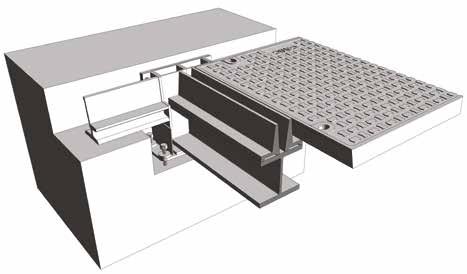
The table shows maximum beam length against beam size.
The removable support beams are supplied by Gatic.
The table also indicates dimensions of the beam wallbox and rebate to suit different beam sizes. See also the accompanying section details.
Section C - C urpose without permission © 2017 n correctly interpreted GATIC C prior to an order being placed h it was created Rev Revision Date Sig A FIRST ISSUE 27/06/2019 P S X W DIRECTION FOR SLIDING OUT COVER Removable support beam (supplied by Gatic) V 145 20 Y L Pit clear opening length ver & rebates to be filled with 45 cube or 40 cylinder crete during installation using 10mm coarse aggregate Full height web structure Solid top cover Suggested rebate for beam wallbox Beam Size
required beam size
covers
dependent
the pit clear opening length and the loading group.
for Multispan
is
on
Removable support beam size Max pit clear opening length (L) Beam wallbox dimensions V W X Y 356 x 171 x 67 kg/m U.B 1750 465 487 535 300 457 x 152 x 82 kg/m U.B 2600 568 590 635 300 533 x 210 x 122 kg/m U.B 3600 647 669 715 300 610 x 229 x 140 kg/m U.B 3900 719 741 790 350 Support beam size chart Note: Removable support beams are supplied by Gatic. For clear opening lengths longer than 3900 please refer to our technical department. Type RRF recessed Type RSF solid top Pl h i d d lid t ti A - A Section C - C Section D - D A B B C D D Checked by Da e Scale Project Title Drawing Number Poul on C ose Dover Kent CT17 0UF Eng and Telephone: +44 (0) 1304 203545 Fax: +44 (0) 1304 215001 E Mai : info@gat c com Web: www ga ic com A d v sion of ALUMASC L MITED confidential and the copyright of GATIC and are not to be disclosed loaned copied or used for manufactur ng or tender ng or for any other purpose without permission © 2017 tisfy themselves in respect of the adequacy of the design provided by GATIC It is the Designer's responsibility to ensure that the data has been correctly interpreted GATIC or false nformation supplied by the Designer or misinterpretation of the data supplied For the avo dance of doubt designs provided by GATIC prior to an order being placed t the Designer s own risk Drawings issued by GATIC in respect of an order after that order has been placed shall be fit for the purpose for wh ch it was created Drawn by Rev R TYPE COVERS R TYPE COVERS AND FRAME PLAN, SECTION AND BEAM WALLBOX DETAILSFOR E600 AND F900 OF BROUCHURE P S 27/06/2019 N T S P M N/A Part No A1 Rev Revision Date Sig A FIRST ISSUE 27/06/2019 P S 1 2 5 145 20 Y L Pit clear opening length Y 1 2 5 DIRECTION FOR SLIDING OUT COVER Removable support beam (supplied by Gatic) Recessed cover type RRF Solid top cover type RSF d or ox Suggested rebate for end frame X W DIRECTION FOR SLID NG OUT COVER Removable support beam (supplied by Gatic) V 145 20 Y L Pit clear opening length 1 2 5 1 0 0 10 110 200 490 X B A S Pit clear opening span Cover & rebates to be filled with 45 cube or 40 cylinder concrete during installation using 10mm coarse aggregate Full height web structure Solid top cover Suggested rebate for beam wallbox Suggested rebate for side frame Suggested rebate for beam wallbox Recessed cover type RRF Solid top cover type RSF Multispan covers and frames 23 www.alumascwms.co.uk +44 (0) 1787 475 151 Introduction Specification F900 E600 D400 C250 B125 Additional Covers/Gratings
Assist lift
Gatic has been setting the industry standard for access covers since 1928. Over this time we have developed products to suit many different industries. The Assist lift covers featured in this brochure have been refined over many years and are in serv ice around the world.
Assist lift covers facilitate one person opening of a F900 load rated ductile iron cover either as an individual cover or as part of a multi cover arrangement. The modular nature of the Gatic system of removable covers is designed to provide sealed, uninterrupted access to the services below whether as a single cover, duct or multispan arrangement with removable support beams.
A removable system for virtually any size of pit configuration and loading can be developed. Gatic covers are designed to protect and give access to a diverse range of underground services. Examples include, manhole/pump/valve/transformer chambers, pipe and cable service trenches, cable draw pits, lighting, fuel and fire hydrant pits, machinery/plant access chambers, tunnel shaft access chambers, combined sewer/overflow chambers and storm tie down pits.
Gatic specialise in the design of covers for airports, container ports, dockyards and industrial areas where extreme wheel loadings from aircraft, container carrying equipment and other vehicles may been encountered. Covers are available with recessed tops for concrete infill at site or with solid cast iron tops. Assist lift covers can be incorporated into larger covers for other loading categories upon request.

24 www.alumascwms.co.uk +44 (0) 1787 475 151 Introduction Specification F900 E600 D400 C250 B125 Additional Covers/Gratings
Assist lift
Cover types
Covers are available either recessed for concrete infill at site or with solid ductile iron tops.
Concrete infill recessed covers
Recessed covers are designed for infilling at site. Concrete should be as specified in BS EN 124 - 45/mm2 for a test cube 150mm or 40N/mm2 for a test cylinder 150mm dia x 300mm high, using 10mm coarse aggregate.
Anti-slip surface
Concrete infill covers provide a non-slip surface similar to the surrounding areas, solid top covers incorporate a raised lozenge pattern on the surface.
Materials
The components of Gatic covers are manufactured from the following materials: Ductile iron to BS EN 1563 Structural steel sections (removable support beams) to BS4-1. M-Struts® and hinges in stainless steel grade 304.
Fine tolerances
The seating faces of Gatic covers and frames are machined finished and assembled in metal to metal contact within a tolerance of 0.25mm.
Non-rocking
Correctly installed, Gatic covers will be non-rocking under traffic and sealed against road dirt and other detritus.
Gas, Air & Watertight
A film of graphite grease between the machined contact faces of Gatic covers and frames provides a gas and airtight seal and a watertight joint under normal rainwater conditions.
Removal/Replacement slide-out covers
The machined seating faces facilitate the sliding out of covers for removal and replacement. Lifting keys are available on request for use with cranes and other mechanical devices.
Secure and vandal resistant
Covers are designed to prevent tampering and unauthorised removal without the use of the specially designed Gatic lifting keys. Locking bolts can be fitted to Gatic cover keyways as an additional security feature. Gatic Type SSA covers incorporate a slam latch mechanism complete with a retained locking bolt. Gatic Types RGA and SGA incorporate two locking bolts as standard.
Assist Lift available on all load classes
Closed keyways
Gatic cover keyways are closed and supplied with plastic plugs to prevent them from blocking with detritus.
Safe Lifting – Assist lift covers
Gatic Assist lift covers have been designed to be lifted and closed by a single operator. The maximum lifting and closing force will be approximately 25kg depending on the size, type and lifting characteristic that has been chosen.
M-Struts®
M-Struts® are designed for demanding environments and provide a maintenance free alternative to conventional gas struts. M-Struts® are made of grade 304 stainless steel. Unlike gas and pneumatic models, M-Struts® have no internal gases to leak or seals to fail in extreme conditions.
Hinges
Gatic Assist lift covers are supplied with flush-fitting hinges as standard but can be supplied with barrel hinges upon request.
Loadings
All Gatic covers within this brochure will withstand the test load, deflection and maximum deformation criteria specified in BS EN 124 for load category F900. Recessed cover are tested in their in-service conditions
Please note:
Gatic do not recommend the use of assist lift covers in high density traffic conditions.
Beam wallbox
Supporting beams in Gatic multispan units can be easily removed with the appropriate lifting equipment to give uninterrupted access to the total chamber area. The beam wallboxes do not project into the chamber opening.
Finishes
Covers and frames are coated with black bituminous solution which forms a temporary protection during transit. Removable support beams are galvanised to BS EN ISO 1461. When installed in extreme environments, the covers and frames can also be galvanised, when specified.
Levelling bolts
All side frame bars and wallboxes are fitted with bolts to assist in the levelling of the unit during installation.
Gatic are usually able to offer assit lift on all load classes and covers within this brochure - installation dependant. Please speak to Gatic technical for the range of options available for your project.
25 www.alumascwms.co.uk +44 (0) 1787 475 151 Introduction Specification F900 E600 D400 C250 B125 Additional Covers/Gratings
Assist lift hinged covers
Areas of exceptionally high wheel loads, aircraft hard-standings, taxiways at civil airports, container ports and dockyards
Gatic Ty pe S SA side hing ed c overs a re a ll assist lift to gi ve complete access to the chamber below.
G ati c stan d-al on e As sist Li ft c overs a re ava ilable i n a va riet y of c onfigurati on s.
Single, soli d- to p As sistLi ft c over –Ty

Th


Tw o- pa rt s olid -top c over – Ty pe S SA Th es e are fi tted w it h a re mova bl e ce ntra l suppor t ba r.
pe S SA
re e- pa rt s olid -top c over –Ty pe S SA Ty pica l sections of soli d- to p cover – Ty pe S SA Gatic wi th s id e hinged A ssistLif t covers Th es e ca n be s upplie d in standard units a s pe r t he s izes s hown o n th e char t below. Longer l engths a re ava ilable Numb e r of cover pa rts are show n in t he b oxes unde r t he standard pi t clea r o p enin g length ( L) Cover op e n – fron t view Cover closed – side v ie w Pi t clea r o pening Spa n (S) So lid To p Cover ty pe Standa rd P it c lea r o pening l ength s ( L) 75 015702 39 03 2104 03 04 90 05770 76 0S SA 123456 7 Pi t clea r o pening Spa n (S) So lid To p Cover ty pe Standa rd P it c lea r o pening l ength s ( L) 90 018702 84 03 810478 0575 0672 0 910S SA 123456 7 PIT CLEAR OP EN ING 150 150 14 0 14 CAPT IVE LATC H LOCK ING BO LT RE BATE TO BE ILLED WITH C45 CONC RETE DU RING INSTALLATION Support frame between covers is removable to give uninterrupted access to the chamber below "Pit clear opening span (S)" "Solid Top Cover type" Standard pit clear opening length (L) 750 1600 2450 3300 4150 5000 5850 760 SSA 1 2 3 4 5 6 7 "Pit clear opening span (S)" "Solid Top Cover type" Standard pit clear opening length (L) 900 1900 2900 3900 4900 5900 6900 910 SSA 1 2 3 4 5 6 7
26 www.alumascwms.co.uk +44 (0) 1787 475 151 Introduction Specification F900 E600 D400 C250 B125 Additional Covers/Gratings
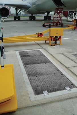
Gatic Ty pe R GA a nd SGA end hinged cove rs give comple te acces s to the chamber opening w hen used as a single cover. W hen integrate d as par t of a duct or multispan ar ra ngemen t, t hey prov ide either one person access to a chamber a bove a ladder or a cces s to e quipment that would need to be inspec te d/operated on a re gular basis Cove rs are available fo r indi vidual leng ths according selecte d – either 7 clear opening span.
Single
Four-par

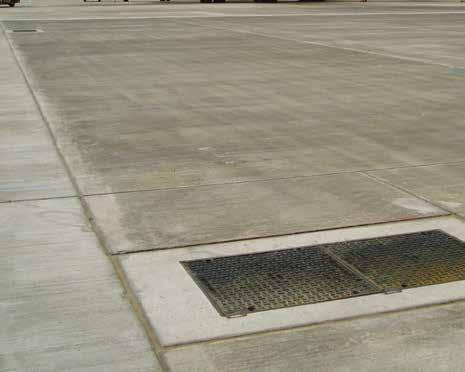


A ssistL if t
re cessed wi th e nd A ssistL
Double,
den
sistLi ft c Standard cros s sections Ty pe S G A – closed s id e view Ty pe R G A – cover op en f ro nt v ie w G ati c re cessed o r soli d to p cove rs a nd f ra me s wi th o ne A ssistL if t cover at the reve rs e en d of the u ni t. These ca n be s upplie d in standard units a s p e r t he s izes s hown o n th e char t belo w. Longer l engths a re ava ilable Numb er of c over p ar ts a re shown i n th e boxe s unde r t he standard pi t c lea r o pening l ength (L) Pi t clea r openin g Spa n (S) So lid To p Cove r ty pe Recessed Cover t yp e Standa rd Pit c lear o pening l engths ( L) 75 09 00 14 50 16 00 1750 19 00 2150 23 00 24 50 26 00 2750 28 50 29 00 3 000 3150 75 0S GA RG A1 *2 22 *3 3 3334 *4 4 90 0 SG AR GA * 1 * 22 2 ** * 33 * 3 ** 33 00 3450 3750 3850 39 00 40 00 4150 42 50 4300 4450 46 00 4750 4850 49 00 4950 75 0S GA RG A4 44 5* 5 5555556 *7 90 0 SG AR GA * 4 4* 4 *** 55 5 5* 5 * *I ndicates n on ava ilabli ty of a produc t fi tted w it h an a ssist lift c over 1 200 20 PIT CLEAR OP EN ING PIT CLEAR OP EN ING 1 65 200 200 RE BATE TO BE ILLED WITH C45 CO NC RETE DU RING INSTALLATI ON Pit clear opening span (S) Cover type Standard pit clear opening length (L) 750 900 1450 1600 1750 1900 2150 2300 2450 2600 2750 2850 2900 3000 3150 3300 3450 3550 750 SFA 1 * 2 2 2 * 3 3 3 3 3 4 * 4 4 4 4 5 900 SFA * 1 * 2 2 2 * 3 3 3 3 * 3 4 4 4 4 * Pit clear opening span (S) Cover type Standard pit clear opening length (L) 3600 3700 3750 3850 3900 4000 4150 4250 4300 4400 4450 4550 4600 4700 4750 4850 4900 750 SFA 4 5 4 5 * 5 5 6 5 6 5 6 5 6 5 6 * 900 SFA 4 5 4 5 4 5 5 * 5 6 5 6 5 6 5 6 5 C k d b P T Draw ng Numbe DO NOT SCALE CT 7 0UF E p F +4 3 4 2 50 1 g W b www ga om SC Th s d aw ng and any n o ma on or desc p ve ma e se ou he eon are con den a and he copy gh of GAT C and are no o be d sc osed oaned cop ed or used o manu ac u ng o ender ng or or any o he pu pose w hou pe m s on © 2017 Des gne s nc ud ng bu not m ed o Eng nee s and A ch ec s mus sa s y hemse ves n espec o he adequacy o he de gn p ov ded by GAT C t s he Des gne s espons b o ensu e ha he da a has been co ec y n erp e ed GAT C pt b y f d q d g b d t d f t pp d b h D g p h d pp d F h d d b d g p d d by GAT C p d b g p d p p y d h d t b d p h D g k D g d by GAT C p d ft h d h b p d h b h p p h h d D b Rev R COVERS R RANGE ASSIST L FT S NGLE CROSS SECT ON BROCHURE DETA LS SK/1479 A P M N T S C G A1 S A R T S UE 2 0 01 M 200 PIT CLEAR OPEN NG 200 1 4 5 1 4 5 200 P T CLEAR OPEN NG 200 Reba es to be led w h 45N/mm² fo es cube o 150mm or a 40N/mm² fo es cy nder 150mm diame er x 300mm h gh concre e dur ng nsta ation us ng 10mm down coarse aggrega e Da e Sca e P T e DO NOT SCALE Th s d aw ng and any n o ma on o descr p ve ma er e ou he eon a e con den a and he copy gh o GAT C and a e no o be d sc osed oaned cop ed o used o manufac u ng o ende ng o o any o he purpo e w thou pe m ss on © 2017 D g d g b d E g d A h t h p h d q h d g p d d by GAT C h D g p b y h h d h b p d GAT C p b y d q d g b d d pp d by h D g p h d pp d F h d d b d g p d d by GAT C p d b g p d a e o us a ve purposes on y and shou d no be e ed upon save or a he De gne s own sk D aw ngs ssued by GAT C n respec o an o de a e ha o de has been p aced sha be o he purpose or wh ch was c ea ed R RANG SEC P M 2 10/2019 N S K C G N A P N A1 Re R v A F RS SSU 200 P T CLEAR OPEN NG 200 1 4 5 1 4 5 200 P T CLEAR OPENING 200 Rebates o be f ed w th 45N mm² or test cube of 150mm o a 40N mm² for test cy inder 150mm d amete x 300mm high concrete dur ng ns a lat on us ng 10mm down coarse agg egate 900 span only. SFA Solid Top SFA RSF SFA Assist lift hinged covers 27 www.alumascwms.co.uk +44 (0) 1787 475 151 Introduction Specification F900 E600 D400 C250 B125 Additional Covers/Gratings
t soli
d As
Areas of exceptionally high wheel loads, aircraft hard-standings, taxiways at civil airports, container ports and dockyards
Gatic multispan access covers incorporate removable support beams so that much larger pit openings can be covered. The table shows standard multispan units that can have an AssistLift cover installed at the back end of the unit. In some cases, more than one AssistLift cover can be fitted
Gatic multispan access c overs incorporate re mova ble suppor t beams so that much larger pit openings can be covered. Th e table shows standar d multispan units that can have an AssistLif t cover installe d at the back end of the unit. In some cases, more than one AssistLif t cover c an b e fitted.
These heavy duty covers are specifically designed for airports, container ports and docks where abnormal wheel loadings from heavy vehicles are envisages
Assist Lift covers can also be fitted to the front end of a unit providing it is in a different span to an Assist Lift cover at the back end.
Th e dimensions sho wn in gree n c an b e fitted w ith a 75 0 x 75 0 clear opening AssistLift c over. Whilst the dimensions shown inre d c an b e fitted w ith a 900 x 900 clea r opening A ssistL if t cover. Typical c ros s section and b eam sizes ca n be found on the page opposite.
Th ese heav y duty c overs are sp ecifically designe d for airpor ts, co ntainer por ts an d docks wh ere abnormal w heel loadings from heav y vehicles are envisaged.
Please refer to our technical dep ar tment with details of specific requirements so that a detailed proposal may be prepared.
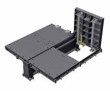


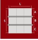


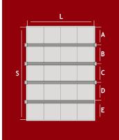
183 0 3060 840 840 840 990 690 840 840 840 990 990 840 840 990 990 990 990 690 840 990 990 930 780 930 1080 930 1080 930 930 930 930 1080 1080 690 840 840 840 990 990 930 930 930 930 1080 1080 690 840 780 780 840 840 780 780 690 840 840 990 840 990 175 0 * 215 0 2300 245 0 260 0 275 0 Pit clear opening length (L) mm Possible number of Assist Lif t Covers 2 parts 1 bea 2 parts 3 parts 4 parts AB CD E 175 0 190 0 * * * 260 0 275 0 A S B L S B S B A B C L S A B C D L S 4020 387 0 840 840 840 990 990 990 990 930 930 930 930 930 1080 1080 780 930 1080 930 1080 930 1080 930 690 930 930 930 840 780 780 780 690 780 930 780 930 930 930 930 1080 1080 840 690 840 690 840 840 990 990 990 990 L A B C D L S L E 1 2 1 * 1 2 3 2 1 * 3 4 3 2 1 * * * 1 2 * * * 1 2 3 * * 1 2 3 4 2 * 1 * 750 900 4 5 4 3 2 1 * * * 1 2 3 4 5 3 * 2 * 1 * Beam Centr es 9 part (3x3) recessed multispan cover with 2 removable support beams 12 part (4x3) recessed multispan cover with ecessed multispan cover with 3 removable support beams 12 part (3x4) recessed multispan cover with 3 removable support beams ecessed multispan cover with 4 emovable support beams 15 part (3x5) recessed multispan cover with 4 removable support beams ecessed multispan cover with 1 emovable support beam 6 part (3x2) ecessed multispan cover with 1 removable support beam 6 part (2x3) recessed multispan cover with 2 emovable support beams * Indicate s n on ava il ab li ty of a produc t fi tted w it h an assist lif t cove
Pit clear opening length (L) mm Possible number of Assist Lift Covers 2 Parts 3 Parts 4 Parts 1450 1600 1750 1900 2150 2300 2450 2600 2750 2900 2850 3000 3150 3300 3450 3600 3750 3900 750 900 Only Max Pit clear opening span (S) mm 2 Parts 1 Beam 1530 1 * 1 1680 2 1 2 1830 1 1 2 1980 * 2 2 3 Parts 2 Beams 2310 1 * 1 2460 2 1 2 2610 3 1 3 2760 2 2 3 2910 1 2 3 3060 * 3 3 4 Parts 3 Beams 3090 1 * 1 3240 2 1 2 3390 3 1 3 3540 4 2 4 3690 3 2 4 3840 2 3 4 3990 1 3 4 4140 * 4 4 5 Parts 4 Beams 3870 1 * 1 4020 2 1 2 4170 3 1 3 4320 4 2 4 4470 5 2 5 4620 4 3 5 4770 3 3 5 4920 2 4 5 5070 1 4 5 5220 * 5 5 1530 1680 1830 1980 4 part (2x2) multispan cover with 1 removable support beam 6 part (2x3) multispan cover with 2 removable support beam 8 part (2x4) multispan cover with 3 removable support beam 6 part (3x2) multispan cover with 1 removable support beam 9 part (3x3) multispan cover with 2 removable support beam 12 part (3x4) multispan cover with 3 removable support beam 8 part (4x2) multispan cover with 1 removable support beam 12 part (4x3) multispan cover with 2 removable support beam 16 part (4x4) multispan cover with 3 removable support beam 10 part (2x5) multispan cover with 4 removable support beam 15 part (3x5) multispan cover with 4 removable support beam 20 part (4x5) multispan cover with 4 removable support beam Pit Clear Opening Lengths shown in Green cannot be achieved with a 900 Assist Lift Cover Pit Clear Opening Lengths shown in Red cannot be achieved with a 750 Assist Lift Cover For further assistance specifying your Assist Lift requirement within a multispan arrangement, please contact our technical team
Assist lift multispan covers & frames 28 www.alumascwms.co.uk +44 (0) 1787 475 151 Introduction Specification F900 E600 D400 C250 B125 Additional Covers/Gratings
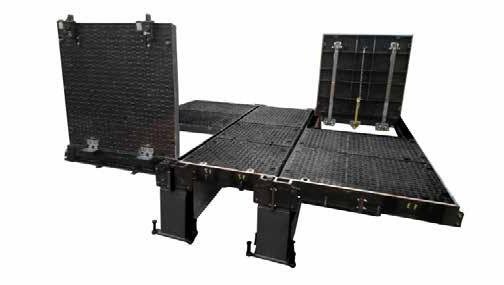

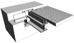

Beam size
Th e re quired beam size for multispan covers is dependant upon the pit clear opening length and the loading g ro up.
Th e table shows the minimum beam length against beam si ze. Th e re mova ble suppor t beams a re sup plied by Gatic
Th e table also shows dimensions of the beam wallbox and r ebate to suit different beam sizes. See also accompanying section details.

Recessed c over –Ty pe R GA Th e detail s b elow s ho w plan a nd s ection s of a ty pical re cesse d top u ni t wi th o ne a ssist lift c over
So lid to p cove r –Ty pe S GA Y Y L Pit clear opening leng th Su ggested rebate for end frame 5 6 1 As sist iftcover type RGA Direction of sliding out covers 150 20 Suggested rebate for beam wall box X W 5 6 1 Removable support beam (supplied by Gatic) A B Recessed top cover type DMR Assist liftcover type RGA 84 0 0 1 0 1 B 0 3 4 0 0 2 0 0 2 n a p s g n n e p o r a e c P S Su ggest ed rebate for end frame 140 165 A Direction of sliding out covers 5 6 1 W X 150 Su ggested rebate for beam wallbox 20 L Pit clear opening ength V 110 10 4 10 5 1 Suggest ed rebate fo side frame Y Co vers & rebates to be filled with 45 cube or 40 cylinder concrete during installation using 10mm coarse aggregate Full heigh web structure Recessed top cover type DMR Su gges ted rebate for beam wallbox 430 A B S Pit cl op ing sp 200 Removable support beam (supplied by Gatic) Solid top coverType RSF Ch k d by D Sca e Pro ect T t e D DO NOT SCALE Th s draw ng and any n o mat on o descr p ve ma ter set ou he eon a e con dent a and he copy ght o GAT C and are not to be d sc osed oaned cop ed o used or manufactur ng o ender ng o or any o he purpose w hou perm ss on © 2017 Des gne s inc ud ng but no m ed to Eng neers and A ch ects must sat sfy themse ves n respec of the adequacy of the des gn p ov ded by GAT C t s the Des gner s esponsibility o ensure hat the data has been co rect y interpreted GATIC accepts no liab ty fo nadequate or inaccurate des gns based on m ted or fa se n ormat on supp ed by he Des gner or m s nterpretat on o the data supp ed For he avo dance of doubt des gns prov ded by GATIC pr or o an order be ng p aced are or ustrative pu poses on y and shou d not be re ed upon save fo at the Des gne s own r sk Draw ngs issued by GAT C n respec of an order a ter tha o der has been placed sha be f fo he pu pose fo wh ch was created D awn by R RANGE SEC P M 29/10/2019 N T S K C G N/A P N A1 Rev Rev s o A F RST SSUE Solid top cover type RSF Assist lift cover type SFA Suggested rebate for beam wallbox Direction for sliding out cover W X 35 175 Y L P t clear opening length Y 1 4 5 Suggested rebate for end frame Assist lift cover type SFA 145 75 2 0 0 S P t c e a r o p e n n g s p a n 1 0 2 0 0 1 1 0 100 B A 4 9 0 Suggested rebate for end frame Direction for s idin W X 35 Y 175 Pit clear op 1 0 0 1 4 5 10 110 200 B S P t clear opening sp Removable support beam (supplied by Gatic) Removable s (suppl ed Suggested rebate for beam wal box Rebates to be filled with 45N/mm² fo of 150mm, or a 40N/mm² for test cy 150mm diameter x 300mm high con nstallat on using 10mm down coars Suggested rebate for beam wa lbox tendering or for any other purpose without permission © 2017 nsure that the data has been correctly interpreted GATIC designs provided by GATIC prior to an order being p aced e fit for the purpose for which it was created Rev Rev s on A F RST ISSUE 29/10/2019 P M 1 4 5 Suggested rebate for end frame Assist lift cover type SFA Direction for sliding out cover W X 35 Y 175 L Pit clear opening length V 1 0 0 Removable support beam (supplied by Gatic) Rebates to be filled with 45N/mm² for test cube of 150mm, or a 40N/mm² for test cylinder 150mm diameter x 300mm high concrete during installation using 10mm down coarse aggregate Suggested rebate for beam wallbox Project Pou on C ose Dover Ken CT17 0UF Eng and Te ephone: +44 (0) 1304 203545 Fax: +44 (0) 1304 215001 E Ma : nfo@gat c com Web: www gatic com A d v s on of ALUMASC LIMITED any nformation or descr pt ve matter set out hereon are conf den ia and the copyr ght of GAT C and are not to be d sclosed oaned copied or used for manufactur ng or tender ng or for any other purpose w thou permiss on © 2017 ing but not l mited to Eng neers and Arch tects mus sa isfy themselves n respect of the adequacy of he des gn provided by GATIC t s the Des gner s respons b ity to ensure that the da a has been correct y nterpreted GAT C y for nadequate or naccurate designs based on lim ted or false nformat on supp ied by he Des gner or m sinterpretat on of he data supp ed For he avo dance of doubt des gns prov ded by GATIC prior to an order be ng placed purposes only and should not be rel ed upon save for at the Des gner s own risk Drawings ssued by GAT C in respect o an order after hat order has been p aced shal be it for the purpose for which t was created D awn by R COVERS P M Rev Rev s on Da e S g A FIRST ISSUE 29/10 2019 P M Solid top cover type RSF Suggested rebate for beam wallbox Direction for sliding out cove W X 35 175 Y L Pit clear opening length Y Suggested b t f Assist lift cover type SFA 2 0 0 S P i t c l e a r o p e n i n g s p a n 1 0 1 1 0 4 9 0 Suggested rebate for end frame Direction for sliding out cover Y L Pit clear opening length 1 0 0 1 4 5 10 110 200 B A S Pit clear opening span 490 Removable support beam (supplied by Gatic) Suggested rebate for beam wallbox Rebates to be filled with 45N/mm² for test cube of 150mm, or a 40N/mm² for test cylinder 150mm diameter x 300mm high concrete during installation using 10mm down coarse aggregate for beam wallbox Ch k d by Da e Sca e Pro ect T e D DO NOT SCALE Th s d awing and any nfo mation or descr p ve mat er set out he eon a e conf dent a and he copy gh of GAT C and are not o be disc osed oaned copied or used or manufac ur ng o tender ng or fo any o her purpose wi hout pe miss on © 2017 Des gners nc uding but no m ed to Eng neers and Arch tects must sat sfy themselves in espec of he adequacy of he des gn prov ded by GATIC t s he Des gner s respons b ty to ensu e that he da a has been co rectly n erp e ed GATIC accep s no ab ty for nadequa e or naccu a e des gns based on lim ed or a se nfo mat on supp ed by the Designer o m sinterp etat on of the da a supp ed Fo he avo dance o doubt designs prov ded by GAT C pr o o an o der be ng p aced are or ust a ve purposes only and shou d no be e ed upon save for at he Des gner s own risk D aw ngs ssued by GATIC in espec of an o der af er ha orde has been p aced sha be fi for the purpose for wh ch it was crea ed D awn by R RANGE SEC P M 29/10/2019 N T S K C G N/A P N A1 Rev Rev s o A F RST SSUE Sol d top cover type RSF Assist ift cover type SFA Suggested rebate for beam wa lbox D rect on for slid ng out cover W X 35 175 Y L Pit clear opening length Y 1 4 5 Suggested rebate for end frame Assist ift cover type SFA 145 75 2 0 0 S P t c e a r p e n i n g s p a n 1 0 2 0 0 1 0 100 B A 4 9 0 Suggested rebate for end frame Direction for slidin W X 35 Y 175 L Pit clear op 0 0 1 4 5 10 110 200 B S Pit clear opening spa Removable support beam (suppl ed by Gat c) Removab e s (supp ied Suggested rebate for beam wal box Rebates to be f l ed with 45N/mm² fo of 150mm or a 40N/mm² for test cy 150mm d ameter x 300mm h gh con installation using 10mm down coars Suggested rebate for beam wallbox 2600 3600 Assist lift multispan covers & frames 29 www.alumascwms.co.uk +44 (0) 1787 475 151 Introduction Specification F900 E600 D400 C250 B125 Additional Covers/Gratings
LFA
Materials
The components of Gatic LFA Assist lift covers are manufactured from the following materials: Ductile iron to BS EN 1563. M-Struts® and other parts in stainless steel grade 304.
Safe Lifting
Gatic LFA Assist lift covers have been designed to be lifted and closed by a single operator. The maximum lifting and closing force will be approximately 25kg.


M-Struts®
M-Struts® are designed for demanding environments and provide a maintenance free alternative to conventional gas struts. M-Struts® are made of grade 304 stainless steel. Unlike gas and pneumatic models, M-Struts® have no internal gases to leak or seals to fail in extreme conditions.
Loadings
Gatic LFA Assist lift covers will withstand the test load, deflection and maximum deformation criteria specified in BS EN 124 for load category F900. Gatic LFA Assist lift covers are suitable for installation in areas subject to slow moving traffic.
Features
• Automatic engaging mechanism to prevent accidental closure.
• Slam latch.
• Locking feature – single Allen key required for opening.
• Integrated lifting handle.
• For sealed Assist lift options please see page 28 - 35


Pit clear opening (mm) Overall Frame depth Overall depth Total weight Load rating 750 x 750 983 x 958 118 142 202kg F900 983 958 142 118 TOP VIEW SIDE VIEW 764 764 TOP VIEW (FRAME ONLY 1133 1108 TOP VIEW FRAME ONLY) TOP VIEW 914 914 162 118 SIDE VIEW 1133 1108 TOP VIEW (FRAME ONLY) TOP VIEW 914 914 162 118 SIDE VIEW Pit clear opening (mm) Overall Frame depth Overall depth Total weight Load rating 900 x 900 1133 x 1108 118 162 252kg F900 SECTION A - A COVER SHOWN N OPEN POS T ON SECTION B - B COVER SHOWN N OPEN POS T ON B DO NOT SCALE Abbreviat ons: Cent e Line C ear Open ng Nominal Overa C NOM O A C O This draw ng and any nformat on o descrip ve ma ter se out he eon are confident al and he copyr gh o GATIC and are not to be d sclosed loaned cop ed or used for manufactur ng or tendering o or any other purpose w hou permiss on © 2017 n fur herance o our po icy o continua development we rese ve he r gh to change he des gn o he components ncorporated hereon wi hou not ce Des gners nc ud ng bu no m ed to Eng neers and Arch ects must sa s y themse ves n respec of he adequacy o he design prov ded by GATIC is the Des gner s espons b ty to ensure tha he data has been correct y n erpreted GATIC accepts no ab y or nadequa e or naccurate des gns based on m ted or a se informat on supplied by he Des gner or m s n e pretat on o he data supp ed For he avo dance o doub des gns provided by GAT C prior o an order be ng p aced a e for ust a ve purposes on y and shou d no be re ed upon save o at he Designe s own r sk Draw ngs ssued by GATIC n respec of an order a ter tha order has been p aced sha be t or he purpose or wh ch was c eated Rev A 1 1 8 1 4 5 7 150 104 900 P T CLEAR OPEN NG SPAN 7 104 150 SUGGESTED FRAME REBATE M-STRUT M-STRUT PROP LOCK M-STRUT SUGGESTED FRAME REBATE 1 1 8 1 4 5 7 150 845 ACTUAL PIT CLEAR OPENING 55 900 PIT CLEAR OPENING LENGTH 150 NOTES: 1 ALL D MENS ONS ARE IN M LL METRES (m 2 MATER AL: DUCT LE CAST IRON TO BS EN 1563 : 20 SPHERO DAL GRAPH TE GRADE 600 3 3 F N SH: UNITS ARE COATED W TH A BLACK B TUM THAT ACTS AS A TEMPORARY PROTECT M-STRUTS ARE SELF COLOUR STA NLES PROP-LOCK S POWDER COATED YELLO 4 LOAD NG BS EN 124 : 1994 F900 SU TABLE FOR 20 TONNE WHEEL L 5 ASSIST L FT COVER (TYPE SGA/SSA OPE APPROXIMATELY 25kg 6 GAT C DO NOT RECOMMEND THE USE O N H GH DENS TY TRAFF C LOCATIONS 7 BEFORE COMMENCING S TE NSTALLATI TO SETTING NSTRUCT ONS SUPPLIED COVER WEIGHT COMPLETE SUPPL ED UN T WEIGHT - 249 kg 900 x 900 LFA COVER ONLY WE GHT - 154kg 90 ° ISOME NOT PLAN SECTION A - A COVER SHOWN N OPEN POS TION SECTION B - B SECTION B - B COVER SHOWN IN OPEN POSIT ON B B A A C d y Date Sca e DO NOT SCALE D w b P M 23/12/2019 App oved Pu chase O der No Abb ev a ions: Centre L ne C ear Open ng Nom na Overa l C NOM O A C O Th s d aw ng and any n o mat on or desc p ve ma e se ou he eon are con den a and the copyr gh o GAT C and a e no to be d sc osed oaned cop ed o used for manu ac u ng o tende ng o or any o he pu pose w thou pe m ss on © 2017 n ur he ance o our po cy o con nua deve opment we eserve the gh to change he des gn of he components nco pora ed hereon w hout no ce Sa es O der No 1 6 K C G A1 Des gne s nc ud ng bu no m ted o Eng nee s and Arch tec s mus sat s y hemse ves n espec of he adequacy o the des gn p ov ded by GAT C s he Des gner s respons b y o ensu e ha he da a has been co ec y nte p eted GAT C accep s no ab ty or nadequate or naccura e des gns based on m ed or a se n o ma on supp ed by he Des gne or m s n e pre a on o the da a supp ed For he avo dance o doub des gns p ov ded by GAT C p or o an o de be ng p aced are o ust at ve pu poses on y and shou d not be e ed upon save o at he Des gner s own sk Draw ngs ssued by GATIC n espec o an order a te tha o de has been p aced sha be o the purpose o wh ch was crea ed Rev A F RST SSUE PROP LOCK M-STRUT FRAME LEVELL NG PO NT 750 P T CLEAR OPEN NG SPAN 7 5 0 P T C L E A R O P E N N G L E N G T H LOCK NG FEATURE L FT NG HANDLE SUGGESTED FRAME REBATE FRAME L FT NG PO NT FRAME LEVELL NG PO NT 1 1 8 1 4 5 7 150 104 750 P T CLEAR OPEN NG SPAN 7 104 150 SUGGESTED FRAME REBATE M-STRUT M-STRUT PROP LOCK M-STRUT SUGGESTED FRAME REBATE 1 1 8 1 4 5 90 7 150 703 ACTUAL P T CLEAR OPEN NG 47 750 PIT CLEAR OPEN NG LENGTH 150 1 1 8 1 4 5 7 150 104 7 129 150 750 PIT CLEAR OPEN NG LENGTH FRAME LEVELL NG PO NT REBATES TO BE FILLED W TH 45 CUBE OR 40 CYL NDER CONCRETE DUR NG NSTALLAT ON USING 10mm COARSE AGGR GATE NOTES: 1 ALL D MENS ONS ARE IN M LL METRES mm) 2 MATER AL: DUCT LE CAST RON TO BS EN 1563 : 2011 SPHERO DAL GRAPH TE) GRADE 600/3 3 FIN SH: UN TS ARE COATED W TH A BLACK B TUMINOUS SOLUT ON THAT ACTS AS A TEMPORARY PROTECT ON DUR NG TRANS T M-STRUTS ARE SELF COLOUR STA NLESS STEEL F NISH PROP-LOCK S POWDER COATED YELLOW 4 LOAD NG BS EN 124 1994 F900 SUITABLE FOR 20 TONNE WHEEL LOAD 5 ASS ST LIFT COVER TYPE SGA SSA) OPERATING WE GHTAPPROX MATELY 25kg 6 GAT C DO NOT RECOMMEND THE USE OF SOL D TOP COVERS N H GH DENSITY TRAFF C LOCATIONS 7 BEFORE COMMENC NG SITE NSTALLAT ON REFER TO SETT NG NSTRUCT ONS SUPPL ED COVER WEIGHT COMPLETE SUPPLIED UN T WEIGHT - 202 kg 750 x 750 LFA COVER ONLY WE GHT - 118kg 30 www.alumascwms.co.uk +44 (0) 1787 475 151 Introduction Specification F900 E600 D400 C250 B125 Additional Covers/Gratings

E600
Introduction Specification F900 E600 D400 C250 B125 Additional Covers/Gratings
Loading group E600 introduction
Areas of high wheel loads, some aircraft hard-standings, dockyards and other areas where heavy duty plant and vehicles may be used
20 tonne wheel load, test load 600kN – Suitable for:
• Some airfield pavements dockyards
• Dockyards
• Other areas where single slow moving wheel loads up to 20 tonne may be encountered


E600 assemblies are available with a choice of cover designs – recessed or solid top.
Recessed for concrete infill Recessed covers are available in a choice of designs designated by a ‘Type’ reference. E600 recessed covers are available as Type DLF, DM, DM/F, RRF. Section drawings of the different recessed cover types are shown on the following pages.
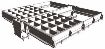
Solid top
Solid top cover types are lighter in weight than recessed covers, and feature an anti-slip surface.
Solid top covers are denoted by the code Type RSF depicted in section on the following pages.


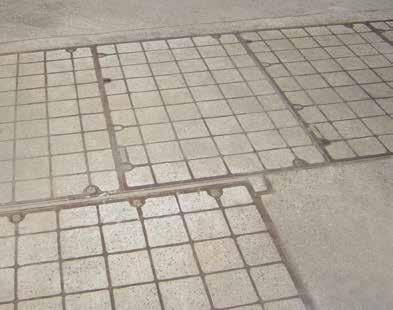

To prevent movement of covers in high traffic conditions, we recommend the use of a factory fitted vibration-resistant locking system. These can be fitted to recessed covers only.
If you are uncertain as to the adequacy of covers conforming to a particular loading, we recommend specifying covers in a higher loading group. For example, if in doubt about covers in Loading Group E600, we recommend you specify covers in Loading Group F900.
Single covers and frames
Duct covers and frames
Continuous trench covers and frames
Multispan covers and frames
32 www.alumascwms.co.uk +44 (0) 1787 475 151 Introduction Specification F900 E600 D400 C250 B125 Additional Covers/Gratings
Product Ranges
Single recessed covers and frames
Areas of high wheel loads, some aircraft hard-standings, dockyards and other areas where heavy duty plant and vehicles may be used
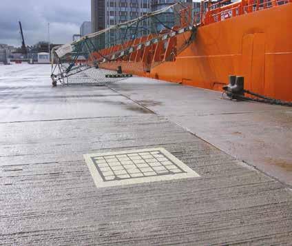
• Covers recessed for concrete infill
• Cover type: DLF, DM/F, DM, RRF
To specify state:
1. Loading group
2. Pit clear opening size length (L) x span (S)
3. Cover type

Pit clear opening sizes L x S Cover type Overall frame size length x width x depth Suggested rebate size length x width x depth 750 x 300 DLF 900 x 540 x 75 1050 x 600 x 100 600 x 450 RRF 750 x 690 x 100 1000 x 850 x 125 750 x 450 RRF 900 x 670 x 100 1150 x 850 x 125 600 x 600 RRF 750 x 840 x 100 1000 x 1000 x 125 750 x 600 RRF 900 x 840 x 100 1150 x 1000 x 125 900 x 600 RRF 1050 x 840 x 100 1300 x 1000 x 125 750 x 750 RRF 900 x 990 x 100 1150 x 1150 x 125 900 x 750 RRF 1050 x 990 x 100 1300 x 1150 x 125 900 x 900 RRF 1120 x 1140 x 100 1300 x 1300 x 125 600 x 1050 DM 820 x 1270 x 140 1000 x 1450 x 165 750 x 1050 DM 970 x 1270 x 140 1150 x 1450 x 165 1000 x 1050 DM 1220 x 1270 x 140 1400 x 1450 x 165 600 x 1200 DM 820 x 1420 x 140 1000 x 1600 x 165 750 x 1200 DM 970 x 1420 x 140 1150 x 1600 x 165 600 x 1500 DM/F 820 x 1720 x 140 1000 x 1900 x 165 750 x 1500 DM/F 970 x 1720 x 140 1150 x 1900 x 165
Plan of recessed single cover Plan of recessed duct cover Section A - A Ch k d by D Sc e Pro ec T e Draw ng Number DO NOT SCALE P C D K C g e ep e 0) 30 03 5 a 0 30 500 E Ma n o@g c om Web www ga c om A d v s on o ALUMASC L M TED Th s draw ng and any n o ma on o desc pt ve ma te se ou hereon are conf den a and he copyr gh of GAT C and a e not o be d sc osed oaned cop ed or used or manu actur ng o tender ng or or any other pu pose w hout perm ss on © 2017 Des gne s nc ud ng bu no m ed to Eng nee s and A ch ec s mus sat s y hemse ves n respect of he adequacy of he des gn prov ded by GAT C s the Des gner s respons b y o ensu e ha he da a has been cor ec y nte p eted GAT C accep s no ab y fo nadequate or naccu ate des gns based on m ed o fa se n orma on supp ed by the Des gner or m s n erpre a on o the data supp ed Fo he avo dance o doubt des gns p ov ded by GATIC pr o o an o der be ng p aced are o us a ve purposes on y and shou d no be re ed upon save o a he Des gne s own r sk Draw ngs ssued by GAT C n espec o an o de a er ha o der has been p aced sha be o the purpose for wh ch was created D b Rev R TYPE COVERS R TYPE COVERS AND FRAME PLAN NCLUD NG SECT ON DETAILS - FOR E600 AND F900 OF BROUCHURE EG/4587 A P S 27 06 2019 N T S P M N/A P N A1 Rev Rev sion Date S g A F RST ISSUE 27/06/2019 P S Length (L) Length (L) S p a n ( S ) S p a n ( S ) Sugested rebate line Sugested rebate l ne 1 0 0 1 2 5 S P t clear opening span 200 110 10 Cover & rebates to be f l ed w th 45 cube or 40 cylinder concrete dur ng installation using 10mm coarse aggregate 7 5 Fu l height webs Suggested rebate line Plan of recessed cover
Type DM / DM/F Type DLF Type RRF Cover Types 75 57 100 110 10 150 S Pit clear opening span Full height webs Cover & rebates to be filled with 45 cube or 40 cylinder concrete during installation using 100 coard aggregate 140 84 165 100 10 200 S Pit clear opening span Full height webs Cover & rebates to be filled with 45 cube or 40 cylinder concrete during installation using 100 coard aggregate Full height webs Pit clear opening span Section A-A 200 125 10 110 100 75 S Cover & rebates to be filled with 45 cube or 40 cylinder concrete during installation using 100 coard aggregate 33 www.alumascwms.co.uk +44 (0) 1787 475 151 Introduction Specification F900 E600 D400 C250 B125 Additional Covers/Gratings

Areas of high wheel loads, some aircraft hard-standings, dockyards and other areas where heavy duty plant and vehicles may be used Cover
• Covers with solid top
• Cover type RSF
To specify state:
1. Loading group
2. Pit clear opening size length (L) x span (S)
3. Cover type

Pit clear opening sizes L x S Cover type Overall frame size length x width x depth Suggested rebate size length x width x depth 600 x 600 RSF 750 x 840 x 100 1000 x 1000 x 125 750 x 600 RSF 900 x 840 x 100 1150 x 1000 x 125 900 x 600 RSF 1050 x 840 x 100 1300 x 1000 x 125 700 x 700 RSF 850 x 940 x 100 1100 x 1100 x 125 750 x 750 RSF 900 x 990 x 100 1150 x 1150 x 125 900 x 750 RSF 1050 x 990 x 100 1300 x 1150 x 125 900 x 900 RSF 1120 x 1140 x 100 1300 x 1300 x 125 1000 x 1000 RSF 1220 x 1240 x 100 1400 x 1400 x 125 Plan of solid top single cover Plan of solid top duct cover Section A - A Checked by Date Sca e P o ec T t e D aw ng Number DO NOT SCALE Pou on C ose Dove Ken CT17 0UF Eng and Te ephone +44 0) 1304 203545 Fax +44 (0 1304 215001 E M @g Web: www ga c com A d ALUMASC L M TED Th s d aw ng and any n ormation or descr ptive matte se out he eon are con den a and he copyright of GAT C and are not to be d sc osed oaned cop ed or used fo manufac ur ng or ende ng or fo any o he purpose w thout pe m ss on © 2017 Des gne s nc ud ng bu not m ed to Eng neers and Arch tects must sa s y hemse ves in espect o the adequacy of he des gn prov ded by GAT C t s the Des gner s respons b lity o ensure ha he da a has been cor ec y n erp e ed GAT C accepts no liab lity or nadequa e or naccurate des gns based on m ted or fa se informat on supp ed by the Des gner o m s nte pre a on of he data supp ed For the avo dance of doubt des gns p ov ded by GATIC p or to an o der be ng p aced are or ustrat ve purposes only and shou d not be re ed upon save for a the Des gner s own r sk Draw ngs ssued by GATIC n respect o an o der a ter that o der has been p aced sha be t or the purpose fo wh ch was c ea ed D by Rev R TYPE COVERS R TYPE COVERS AND FRAME PLAN INCLUDING SECTION DETAILS - FOR E600 AND F900 OF BROUCHURE EG/4590 A P S 27/06/2019 N T S P M N/A P N A1 Rev Revision Date S g A FIRST ISSUE 27/06/2019 P S Length (L) Length (L) S p a n ( S ) S p a n ( S ) Sugested rebate ine Sugested rebate line 1 2 5 S P t clear opening span 200 Rebates to be filled with 45 cube or 40 cy inder concrete during nstallation using 10mm coarse aggregate So id tops covers 1 0 0 110 10 Suggested rebate line Plan of solid cover
solid top covers and
Single
frames
Type RSF Plan of solid top single cover Plan of solid top duct cover Section A - A Checked by Da e Sca e P o ect Tit e Draw ng Number DO NOT SCALE P C D K CT17 0UF E g a d Te ephone +44 0 1304 203545 F +44 0 1304 215001 E Ma nfo@ga c com Web www ga c com A d ALUMASC L M TED d any n o ma on o descr pt ve ma er se ou he eon are con dentia and he copyr ght o GAT C and are no to be disc osed oaned cop ed or used for manufactu ng o tender ng o for any o he purpose w hout perm ss on © 2017 d ng bu no m ted to Eng nee s and Arch ects must sa s y themse ves n espect o the adequacy of he des gn p ov ded by GATIC is the Des gne s espons b y o ensure hat the da a has been cor ect y n erpreted GAT C y or nadequa e o inaccu a e des gns based on lim ed or fa se nforma on supplied by he Des gner o m s n e pretation o the da a supp ed Fo the avo dance of doubt des gns prov ded by GAT C pr or o an o de be ng p aced purposes on y and shou d not be e ed upon save for a the Des gner s own risk Draw ngs ssued by GAT C n respec o an order af e that orde has been p aced sha be t or he purpose o wh ch t was crea ed D awn by Rev R TYPE COVERS R TYPE COVERS AND FRAME PLAN NCLUD NG SECT ON DETA LS - FOR E600 AND F900 OF BROUCHURE EG/4590 A P S 27 06/2019 N T S P M N A P N A1 Rev Revis on Date Sig A FIRST ISSUE 27/06/2019 P S Length (L) Length (L) S p a n ( S ) Sugested rebate line Sugested rebate l ne 1 2 5 S Pit c ear open ng span 200 ebates to be fi led with 45 cube or 40 cy inder oncrete during nsta lat on using 10mm coarse aggregate Sol d tops covers 1 0 0 110 10 Rebates to filled with 45 cube or 40 cylinder concrete during installation using 10mm coarse aggregate For high density traffic conditions refer to page 14. 34 www.alumascwms.co.uk +44 (0) 1787 475 151 Introduction Specification F900 E600 D400 C250 B125 Additional Covers/Gratings
Types

• Covers recessed for concrete infill
• Cover type DLF, RRF, DM, DM/F
To specify state:
1. Loading group
2. Pit clear opening size length (L) x span (S)
3. Cover type

Pit clear opening span (S) Cover type Standard pit clear opening length (L) 2850 2900 3000 3150 3300 3400 3550 3700 3850 3900 4000 4150 300 DLF * * * * 4 * * * * * * 5 450 RRF 4 * 4 4 4 5 5 5 5 * 5 5 600 RRF 4 3 4 4 4 5 5 5 5 4 5 5 750 RRF 4 3 4 4 4 5 5 5 5 4 5 5 900 RRF 4 3 4 4 4 5 5 5 5 4 5 5 1050 DM 4 * 4 4 4 5 5 5 5 * 5 5 1200 DM 4 * 4 4 4 5 5 5 5 * 5 5 1500 DM/F 4 * 4 4 4 5 5 5 5 * 5 5 Pit clear opening span (S) Cover type Standard pit clear opening length (L) 1300 1450 1600 1750 1900 2000 2150 2300 2450 2600 2700 2750 300 DLF * * 2 * * * * * 3 * * * 450 RRF 2 2 2 * * 3 3 3 3 * 4 * 600 RRF 2 2 2 2 2 3 3 3 3 3 4 3 750 RRF 2 2 2 2 2 3 3 3 3 3 4 3 900 RRF 2 2 2 2 2 3 3 3 3 3 4 3 1050 DM 2 2 2 * * 3 3 3 3 * 4 * 1200 DM 2 2 2 * * 3 3 3 3 * 4 * 1500 DM/F 2 2 2 * * 3 3 3 3 * 4 * Pit clear opening sizes Cover type Suggested rebate size length x width x depth 300 DLF (L + 300) x 600 x 100 450 RRF (L + 400) x 850 x 125 600 RRF (L + 400) x 1000 x 125 750 RRF (L + 400) x 1150 x 125 900 RRF (L + 400) x 1300 x 125 1050 DM (L + 400) x 1450 x 165 1200 DM (L + 400) x 1600 x 165 1500 DM/F (L + 400) x 1900 x 165
P an of recessed s ngle cover Plan of recessed duct cover Section A - A Ch k d by D S P o ec T t e D aw ng DO NOT SCALE Th s d aw ng and any n orma on or descr p ve ma er set ou he eon a e con dent a and the copy gh o GAT C and are no o be d sc osed oaned cop ed o used o manu ac u ng or ende ng o o any o he purpose w thou pe m ss on © 2017 Des gners nc ud ng but no m ted o Eng neers and Arch tec s mus sa sfy hemse ves n espec o the adequacy o the des gn prov ded by GAT C s he Des gne s espons b y o ensure ha the data has been co rect y n erpre ed GAT C accepts no ab ty or nadequa e o naccura e des gns based on m ed or a se nfo mat on supp ed by he Des gne o m s nte p eta on o he da a supp ed Fo he avo dance o doub des gns prov ded by GAT C p or o an orde be ng p aced a e or us ra ve pu poses on y and shou d not be e ed upon save for a the Des gner s own sk D aw ngs ssued by GAT C n respec of an order afte hat orde has been p aced sha be f t or he pu pose o wh ch t was c ea ed D awn by R TYPE COV INCLUDING SE AND F9 P S 27 06/2019 N T S P M N A Pa No A1 Rev Revis on A FIRST ISSUE Length (L) Length (L) S p a n ( S S p a n ( S Sugested rebate ine 1 0 0 1 2 5 S P t c ear open ng span 200 110 10 Cover & rebates to be fi led with 45 cube or 40 cy nder concrete during insta at on us ng 10mm coarse aggregate 7 5 Ful he ght webs Suggested rebate line Plan of recessed cover Recessed duct covers and frames Type DM / DM/F Type DLF Type RRF Cover Types 75 57 100 110 10 150 S Pit clear opening span Full height webs Cover & rebates to be filled with 45 cube or 40 cylinder concrete during installation using 100 coard aggregate 140 84 165 100 10 200 S Pit clear opening span Full height webs Cover & rebates to be filled with 45 cube or 40 cylinder concrete during installation using 100 coard aggregate Full height webs Pit clear opening span Section A-A 200 125 10 110 100 75 S Cover & rebates to be filled with 45 cube or 40 cylinder concrete during installation using 100 coard aggregate 35 www.alumascwms.co.uk +44 (0) 1787 475 151 Introduction Specification F900 E600 D400 C250 B125 Additional Covers/Gratings
Recessed duct covers and frames
Areas of high wheel loads, some aircraft hard-standings, dockyards and other areas where heavy duty plant and vehicles may be used
• Covers recessed for concrete infill
• Cover types: DLF, DM, DM/F, RRF
To specify state:
1. Loading group
2. Cover type
3. Supply layout drawing of trenches
Gatic covers can be formed to make continuous trenches or layouts providing total access to services below.
Construction drawings are required so that Gatic cover layout drawings can be prepared.

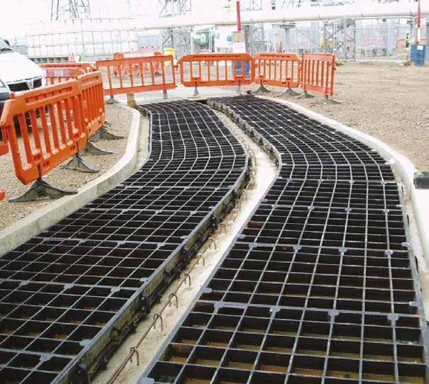
Pit clear opening span Cover type 300 DLF 450 RRF 600 RRF 750 RRF 900 RRF 1050 DM 1200 DM 1500 DM/F
For type DM/F refer to our technical department
Continuous recessed cover
Type DM / DM/F Type DLF Type RRF Cover Types 75 57 100 110 10 150 S Pit clear opening span Full height webs Cover & rebates to be filled with 45 cube or 40 cylinder concrete during installation using 100 coard aggregate 140 84 165 100 10 200 S Pit clear opening span Full height webs Cover & rebates to be filled with 45 cube or 40 cylinder concrete during installation using 100 coard aggregate Full height webs Pit clear opening span Section A-A 200 125 10 110 100 75 S Cover & rebates to be filled with 45 cube or 40 cylinder concrete during installation using 100 coard aggregate 36 www.alumascwms.co.uk +44 (0) 1787 475 151 Introduction Specification F900 E600 D400 C250 B125 Additional Covers/Gratings

• Covers with solid top
• Cover type RSF
To specify state:
1. Loading group
2. Pit clear opening size length (L) x span (S)
3. Cover type

For high density traffic conditions refer to page 14.
Pit clear opening span (S) Cover type Standard pit clear opening length (L) 1300 1450 1500 1600 1750 1900 2000 2150 2300 2450 2600 2700 2750 600 RSF 2 2 * 2 2 2 3 3 3 3 3 4 3 700 RSF * * 2 * * * * * 3 * * * * 750 RSF 2 2 * 2 2 2 3 3 3 3 3 4 3 900 RSF 2 2 * 2 2 2 3 3 3 3 3 4 3 Pit clear opening span (S) Cover type Standard pit clear opening length (L) 2850 2900 3000 3100 3150 3300 3400 3550 3700 3850 3900 4000 4150 600 RSF 4 3 4 * 4 4 5 5 5 5 4 5 5 700 RSF * * * 4 * * * * * * 5 * * 750 RSF 4 3 4 * 4 4 5 5 5 5 4 5 5 900 RSF 4 3 4 * 4 4 5 5 5 5 4 5 5 Pit clear opening sizes Cover type Suggested rebate size length x width x depth 600 RSF (L + 400) x 1000 x 125 700 RSF (L + 400) x 1100 x 125 750 RSF (L + 400) x 1150 x 125 900 RSF (L + 400) x 1300 x 125
Plan of solid top Plan of solid top duct cover Section A - A Checked by Da e S DO NOT S Th s draw ng and any n orma on or descr p ve ma ter set ou hereon are conf dent a and the copyr gh o GATIC and are no o be disc osed oaned cop ed or used or manu ac uring or tender ng or or any other purpose w hou perm ssion © 2017 Des gners nc uding but no m ted o Eng neers and A ch ec s must sat sfy themse ves n respec of the adequacy o he des gn prov ded by GAT C s he Des gne s espons b ty to ensure hat the data has been co rect y nte preted GATIC accep s no ab ty fo nadequa e or naccu ate des gns based on m ed or fa se n orma on supp ed by he Des gner or m s nterpretat on o the da a suppl ed For he avo dance o doubt des gns prov ded by GAT C pr o o an orde be ng p aced a e for i ustra ve pu poses on y and shou d no be re ed upon save for at he Des gne s own sk D aw ngs issued by GAT C n espec o an order af e ha orde has been p aced sha be f fo he pu pose or wh ch it was created D awn by P S 27 06 2019 N T S P M N Pa No A1 Rev A FIRST Length Length (L) S p a n ( S ) S p a n ( S ) Sugested rebate line 1 2 5 S Pit clear opening span 200 Rebates to be fil ed with 45 cube or 40 cylinder concrete during instal at on using 10mm coarse aggregate Solid tops covers 1 0 0 110 10 Suggested rebate line Plan of solid cover Solid top duct covers and frames Cover Types Type RSF Plan of solid top single cover Plan of solid top duct cover Section A - A Checked by Da e Sca e P o ect Tit e Draw ng Number DO NOT SCALE P C D K CT17 0UF E g a d Te ephone +44 0 1304 203545 F +44 0 1304 215001 E Ma nfo@ga c com Web www ga c com A d ALUMASC L M TED d any n o ma on o descr pt ve ma er se ou he eon are con dentia and he copyr ght o GAT C and are no to be disc osed oaned cop ed or used for manufactu ng o tender ng o for any o he purpose w hout perm ss on © 2017 d ng bu no m ted to Eng nee s and Arch ects must sa s y themse ves n espect o the adequacy of he des gn p ov ded by GATIC is the Des gne s espons b y o ensure hat the da a has been cor ect y n erpreted GAT C y or nadequa e o inaccu a e des gns based on lim ed or fa se nforma on supplied by he Des gner o m s n e pretation o the da a supp ed Fo the avo dance of doubt des gns prov ded by GAT C pr or o an o de be ng p aced purposes on y and shou d not be e ed upon save for a the Des gner s own risk Draw ngs ssued by GAT C n respec o an order af e that orde has been p aced sha be t or he purpose o wh ch t was crea ed D awn by Rev R TYPE COVERS R TYPE COVERS AND FRAME PLAN NCLUD NG SECT ON DETA LS - FOR E600 AND F900 OF BROUCHURE EG/4590 A P S 27 06/2019 N T S P M N A P N A1 Rev Revis on Date Sig A FIRST ISSUE 27/06/2019 P S Length (L) Length (L) S p a n ( S ) Sugested rebate line Sugested rebate l ne 1 2 5 S Pit c ear open ng span 200 ebates to be fi led with 45 cube or 40 cy inder oncrete during nsta lat on using 10mm coarse aggregate Sol d tops covers 1 0 0 110 10 Rebates to filled with 45 cube or 40 cylinder concrete during installation using 10mm coarse aggregate For high density traffic conditions refer to page 14. 37 www.alumascwms.co.uk +44 (0) 1787 475 151 Introduction Specification F900 E600 D400 C250 B125 Additional Covers/Gratings

Continuous solid top cover
For high density traffic conditions refer to page 14.
Standard Solid top covers are supplied in straight runs. Junctions and splays can be achieved by the inclusion of localised recessed covers. Refer to our technical department for more information.
• Covers with solid top
• Cover types: RSF
To specify state:
1. Loading group
2. Cover type
3. Supply layout drawing of trenches
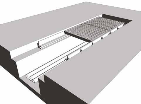
For high density traffic conditions refer to page 14.
Pit clear opening span Cover type 600 RSF 700 RSF 750 RSF 900 RSF
Continuous solid top duct covers and frames Cover Types Type RSF Plan of solid top single cover Plan of solid top duct cover Section A - A Checked by Da e Sca e P o ect Tit e Draw ng Number DO NOT SCALE P C D K CT17 0UF E g a d Te ephone +44 0 1304 203545 F +44 0 1304 215001 E Ma nfo@ga c com Web www ga c com A d ALUMASC L M TED d any n o ma on o m ss on © 2017 d ng bu no m ted t ed GAT C y or nadequa e o e ng p aced purposes on y and D awn by Rev R TYPE COVERS R TYPE COVERS AND FRAME PLAN NCLUD NG SECT ON DETA LS - FOR E600 AND F900 OF BROUCHURE EG/4590 A P S 27 06/2019 N T S P M N A P N A1 Rev Revis on Date Sig A FIRST ISSUE 27/06/2019 P S Length (L) S p a n ( S ) Sugested rebate line Sugested rebate l ne 1 2 5 S Pit c ear open ng span 200 ebates to be fi led with 45 cube or 40 cy inder oncrete during nsta lat on using 10mm coarse aggregate Sol d tops covers 1 0 0 110 10 Rebates to filled with 45 cube or 40 cylinder concrete during installation using 10mm coarse aggregate
38 www.alumascwms.co.uk +44 (0) 1787 475 151 Introduction Specification F900 E600 D400 C250 B125 Additional Covers/Gratings
Multispan covers and frames
Areas of high wheel loads, some aircraft hard-standings, dockyards and other areas where heavy duty plant and vehicles may be used
Specification
Below is a sample specification information and notes for Multispan recessed covers and frames.
For more details on features and benefits of Gatic covers see pages 14
Loading group Gatic E600
20 tonne wheel load – test load 600 kN.
Materials
Ductile iron components to BS EN 1563
Structural steel removable beams to BS EN 10365.
Finishes
Units coated with black bituminous solution for protection during transit.
Removable supporting steelwork galvanised to BS EN ISO 1461.
Infill and surround concrete by customer
Concrete strength, using 10mm down coarse aggregate, to be: 45N/mm2 for a test cube of 150mm or 40N/mm2 for a test cylinder of 150mm diameter x 300mm high.
Installation
In accordance with instructions supplied by Gatic.

RRF recessed

RSF solid top
To specify use size and description format as follows:
Gatic Multispan Recessed covers and frames Cover type RRF recessed Multiple access covers recessed for concrete infill with removable beams.
.... in no. ..... (length) x .... (span) mm pit clear opening multi span cover and frame.
Gatic Type .... Ductile Iron Recessed Cover in .... parts complete with .... in no. .... x .... mm galvanised removable support beam spanning the .... (length) mm way.
Suitable for Loading Group E600 – 20 Tonnes Wheel Load (pneumatic tyre).
Gatic Multispan Solid Top covers and frames Cover type RSF solid top Multiple solid top access covers with removable beams.
.... in no. ..... (length) x .... (span) mm pit clear opening multi span cover and frame.
Gatic Type RSF Ductile Iron Solid Top Cover in .... parts complete with .... in no. .... x .... mm galvanised removable support beam spanning the .... (length) mm way.
Suitable for Loading Group E600 – 20 Tonnes Wheel Load (pneumatic tyre).
Standard pit clear opening sizes are shown on page 45
Beam sizes and other dimensions are shown on page 46 - 47
For high density traffic conditions refer to page 14.
Type
Type
39 www.alumascwms.co.uk +44 (0) 1787 475 151 Introduction Specification F900 E600 D400 C250 B125 Additional Covers/Gratings
Multispan covers and frames
Product Selection
Refer to the table to identify which cover and beam configuration you require against pit clear opening length (L) and pit clear opening span (S). All dimensions are in millimetres.
Note: All dimensions shown in red are made up using 700 x 700 solid top covers only.
1380 1530 1580 1680 1830 1980 2160 2310 2460 2460 2610 2760 2910 3060 3240 3090 2940 3340 3390 3540 3690 3840 3990 4140 690 840 840 990 990 690 690 840 790 840 990 990 840 990 840 840 990 990 990 690 690 790 790 840 840 990 780 930 780 880 1080 930 1080 780 1080 930 930 930 930 1080 690 690 840 790 840 930 840 840 990 990 780 1080 930 930 930 930 1080 840 840 780 780 690 690 780 780 690 990 790 880 880 790 690 840 840 990 840 1300 1450 1500 1600 1750 2000 2150 2300 2300 2450 3000 2850 2700 3100 3150 3300 3450 3600 3750 3900 Pit clear opening length (L) mm Beam centres mm Pit clear opening span (S) mm 4 parts 3 beams 3 parts 2 beams 2 parts 1 beam 2 parts 3 parts 4 parts AB CD E 2600 2750 2900 6 part (2x3) recessed multispan cover with 2 removable support beams 9 part (3x3) recessed multispan cover with 2 removable support beams 12 part (4x3) recessed multispan cover with 2 removable support beams 8 part (2x4) recessed multispan cover with 3 removable support beams 12 part (3x4) recessed multispan cover with 3 removable support beams 16 part (4x4) recessed multispan cover with 3 removable support beams L = Pit clear opening length S = Pit clear opening span Cover Beam Inset lines denote pit opening L A S B L A S B L A S B L A S B C L A S B C L A C S B L A S B C D L A S B C D L A C D S B 4020 3870 3720 4170 4220 4320 4470 4620 4770 4920 5070 5220 690 790 840 840 990 990 990 930 880 930 930 930 930 1080 930 880 930 1080 930 1080 930 930 840 780 780 780 690 780 930 780 690 780 780 780 880 930 930 930 930 990 1080 1080 1080 1080 690 840 690 690 790 840 930 780 930 840 840 840 990 990 990 990 5 parts 4 beams 10 part (2x5) recessed multispan cover with 4 removable support beams 15 part (3x5) recessed multispan cover with 4 removable support beams 20 part (4x5) recessed multispan cover with 4 removable support beams L A S B C D L A S B C D L A C D E E E S B 4 part (2x2) recessed multispan cover with 1 removable support beam 6 part (3x2) recessed multispan cover with 1 removable support beam 8 part (4x2) recessed multispan cover with 1 removable support beam 1900
Note: For other pit clear opening sizes please refer to our technical department 4 part (2x2) multispan cover with 1 removable support beam 6 part (2x3) multispan cover with 2 removable support beam 8 part (2x4) multispan cover with 3 removable support beam 10 part (2x5) multispan cover with 4 removable support beam
part (3x2) multispan cover with 1 removable support beam
part (3x3) multispan cover with 2 removable support beam 12 part (3x4) multispan cover with 3 removable support beam 15 part (3x5) multispan cover with 4 removable support beam 8 part (4x2) multispan cover with 1 removable support beam 12 part (4x3) multispan cover with 2 removable support beam 16 part (4x4) multispan cover with 3 removable support beam 20 part (4x5) multispan cover with 4 removable support beam
6
9
40 www.alumascwms.co.uk +44 (0) 1787 475 151 Introduction Specification F900 E600 D400 C250 B125 Additional Covers/Gratings
Recessed duct covers and frames
Areas of high wheel loads, some aircraft hard-standings, dockyards and other areas where heavy duty plant and vehicles may be used

• Covers recessed for concrete infill or solid top
• Cover types: RRF (recessed) RSF (solid top)
The details below show plan and sections of a typical recessed/solid top unit.
For selection and specification guidance See page 44.
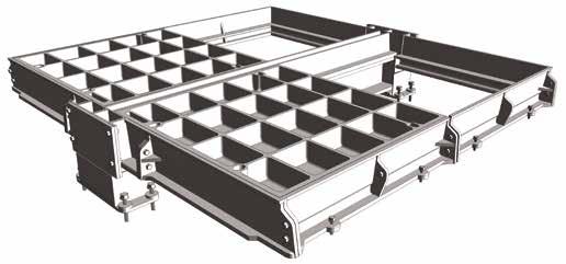
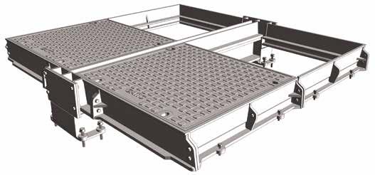
Section
Section
Type RSF solid top Type RRF recessed Plan showing recessed and solid top cover options Section A - A Section B - B Section C - C Section D - D A A B B C C D D Checked by Date Sca e Pro T t e DO NOT SCA Th s draw ng and any nformat on or descr pt ve matter set out hereon are confidential and the copyr ght of GATIC and are not to be disclosed loaned cop ed or used for manufactur ng or tender ng or for any other purpose w thout permiss on © 2017 Des gners nc ud ng bu not im ted to Engineers and Arch tects must sat sfy themse ves n respect of the adequacy o the design provided by GATIC I is the Designer s responsibi ity to ensure that the data has been correctly n erpreted GATIC accepts no iab l ty or nadequate or naccurate des gns based on im ted or fa se n ormat on suppl ed by the Des gner or m sinterpre at on o the data suppl ed For the avo dance of doubt designs prov ded by GATIC pr or to an order being p aced are for lustrative purposes on y and shou d not be re ied upon save for at the Des gner s own risk Drawings issued by GAT C in respec of an order after that order has been placed sha l be f t for the purpose for which it was created Drawn by S P S 27/06/2019 N T S P M N/A Pa t No A1 Rev A FIRST ISS X W 1 2 5 145 20 Y L Pit clear opening length Y 1 2 5 DIRECTION FOR SLIDING OUT COVER Removab e support beam (supp ied by Gatic) Recessed cover type RRF Solid top cover type RSF Suggested rebate for beam wallbox Suggested rebate for end frame 125 100 B A X 4 9 0 S P t c l e a r o p e n i n g s p a n 2 0 0 1 0 1 1 0 85 Suggested rebate for side frame X W D RECT ON FO Remo beam (s 145 20 Y Pit clea 1 2 5 1 0 0 10 110 200 B Cover & rebates to be filled with 45 cube or 40 cylind concrete during installation using 10mm coarse aggr Full Suggested rebate for beam wallbox Suggested rebate for side frame Suggested rebate for beam wa lbox Recessed cover type RRF Solid top cover type RSF A B Plan showing recessed and solid top cover options
A - A
B - B Sectio Section A A B B C C D D eon are confidential and the copyright of GATIC, and are not to be disclosed, loaned, copied or used for manufacturing or tendering or for any other purpose without perm must satisfy themselves in respect of the adequacy of the design provided by GATIC It is the Designer's responsibility to ensure that the data has been correctly interprete limited or false information supplied by the Designer or misinterpretation of the data supplied For the avoidance of doubt designs provided by GATIC prior to an order b e for at the Designer s own risk Drawings issued by GATIC in respect of an order after that order has been placed shall be fit for the purpose for which it was created X W 1 2 5 145 20 Y L Pit clear opening length Y 1 2 5 DIRECTION FOR SLIDING OUT COVER Removable support beam (supplied by Gatic) Recessed cover type RRF Solid top cover type RSF Suggested rebate for beam wallbox Suggested rebate for end frame 125 100 B A X 4 9 0 S P i t c l e a r o p e n i n g s p a n 2 0 0 1 0 1 1 0 85 Suggested rebate for side frame X W 1 2 5 1 0 0 Cover & rebates to concrete during ins Suggested rebate for side frame Sugge reba beam wa Recessed cover type RRF Solid top cover type RSF A B Plan showing recessed and solid top cover options Section A - A Section B - B Section C - C Section D - D A A B B C C D D Checke Date Scale D This drawing and any nformat on or descr ptive matter set out hereon are confidentia and the copyright of GATIC, and are not to be disclosed, oaned, cop ed or used for manufacturing or tender ng or for any other purpose without perm ss on © 2017 Designers, ncluding but not l mited to, Eng neers and Architects, must satisfy themselves in respect of the adequacy of the design prov ded by GATIC It is the Des gner s responsibi ity to ensure that the data has been correctly interpreted GATIC accepts no l ability for nadequate or inaccurate designs based on imited or false information supplied by the Designer or misinterpretation of the data suppl ed For the avo dance of doubt des gns provided by GATIC prior to an order being placed are for i lustrative purposes on y and shou d not be re ied upon save for at the Designer s own risk Draw ngs issued by GATIC n respect of an order after that order has been p aced shall be fit for the purpose for wh ch it was created Drawn Part No R X W 1 2 5 145 20 Y L Pit clear opening length Y 1 2 5 DIRECTION FOR SLIDING OUT COVER Removable support beam (supplied by Gatic) Recessed cover type RRF Solid top cover type RSF Suggested rebate for beam wallbox Suggested rebate for end frame 125 100 B A X 4 9 0 S P i t c e a r o p e n n g s p a n 2 0 0 1 0 1 1 0 85 Suggested rebate for side frame X W 145 Y 1 2 5 1 0 0 10 110 200 Cover & rebates to be filled with 45 cub concrete during installation using 10mm S bea Suggested rebate for side frame Suggested rebate for beam wallbox Recessed cover type RRF Solid top cover type RSF A B
41 www.alumascwms.co.uk +44 (0) 1787 475 151 Introduction Specification F900 E600 D400 C250 B125 Additional Covers/Gratings
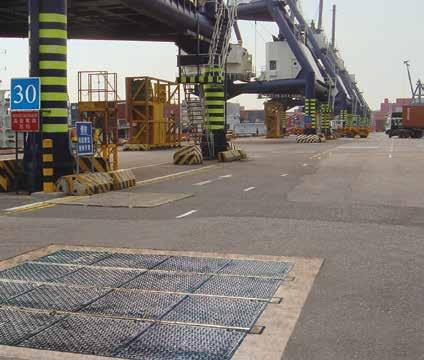
Beam Size
The required beam size for Multispan covers is dependent on the pit clear opening length and the loading group.
The table shows maximum beam length against beam size. The removable support beams are supplied by Gatic.
The table also indicates dimensions of the beam wallbox and rebate to suit different beam sizes.
See also the accompanying section details.
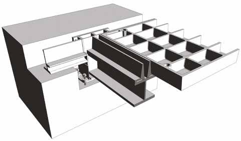

Removable support beam size Max pit clear opening length (L) Beam wallbox dimensions V W X Y 305 x 165 x 54 kg/m U.B 2000 412 434 480 230 356 x 171 x 67 kg/m U.B 2450 465 487 535 300 457 x 152 x 82 kg/m U.B 2850 568 590 635 300 533 x 210 x 122 kg/m U.B 3900 647 669 715 300 Support beam size chart Note: Removable support beams are supplied by Gatic Type RRF recessed Type RSF solid top Section C - C other purpose without permission © 2017 as been correctly interpreted GATIC y GATIC prior to an order being placed or which it was created Rev Revision Date Sig A FIRST ISSUE 27/06/2019 P S ted or me X W DIRECTION FOR SLIDING OUT COVER Removable support beam (supplied by Gatic) V 145 20 Y L Pit clear opening length Cover & rebates to be filled with 45 cube or 40 cylinder Full height web structure Suggested rebate for beam wallbox tion A - A Section C - C Section D - D A A B C D Checked by Date Pro ect T tle Poul on C ose Dover Kent CT17 0UF Eng and Te ephone: +44 (0) 1304 203545 Fax +44 (0) 1304 215001 E Mai nfo@gat c com Web: www gat c com A div s on o ALUMASC L M TED reon are conf dent al and the copyright of GATIC and are not to be disclosed oaned copied or used for manufacturing or tendering or for any other purpose w thout permission © 2017 must satisfy themse ves in respect of the adequacy of the design provided by GAT C It is the Designer's responsibi ity to ensure that the data has been correctly interpreted GATIC n lim ted or false information supp ied by the Des gner or mis nterpretation of the data supp ied For the avoidance of doubt, designs provided by GATIC prior to an order being placed ave for at the Designer s own risk Drawings issued by GATIC in respect of an order after that order has been p aced shal be fit for the purpose for which it was created Drawn by R TYPE COVERS R TYPE COVERS AND FRAME PLAN, SECTION AND BEAM WALLBOX DETAILSP S 27/06/2019 P M Rev Revision Date Sig A FIRST ISSUE 27/06/2019 P S W 1 2 5 145 20 Y L Pit clear opening length Y 1 2 5 DIRECTION FOR SLIDING OUT COVER Removable support beam (supplied by Gatic) Recessed cover type RRF Solid top cover type RSF ggested bate for wallbox Suggested rebate for end frame X W DIRECTION FOR SLID NG OUT COVER Removable support beam (supplied by Gatic) V 145 20 Y L Pit clear opening length 1 2 5 1 0 0 10 110 200 490 X B A S Pit clear opening span Cover & rebates to be filled with 45 cube or 40 cylinder concrete during installation using 10mm coarse aggregate Full height web structure Solid top cover Suggested rebate for beam wallbox Suggested rebate for side frame Suggested rebate for beam wallbox Recessed cover type RRF Solid top cover type RSF A B Solid top duct covers and frames 42 www.alumascwms.co.uk +44 (0) 1787 475 151 Introduction Specification F900 E600 D400 C250 B125 Additional Covers/Gratings

D400
Introduction Specification F900 E600 D400 C250 B125 Additional Covers/Gratings
Loading group D400 introduction
Power stations, Carriageways, hard shoulders, and parking areas for all types of vehicle
11.5 tonne wheel load,test load 400kN – Suitable for:
• Power stations
• Carriageways
• Hard shoulders
• Parking areas for all types of vehicles
D400 assemblies are available with a choice of cover designs – recessed or solid top.
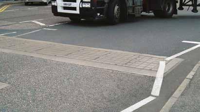
To prevent movement of covers in high traffic conditions, we recommend the use of a factory fitted vibration-resistant locking system. Can be fitted to recessed concrete infill covers only.
If you are uncertain as to the adequacy of covers conforming to a particular loading, we recommend specifying covers in a higher loading group. For example, if in doubt about covers in Loading Group D400, we recommend you specify covers in Loading Group E600.
D400 assemblies are available with a choice of cover designs – recessed or solid top.


Recessed for concrete infill
Recessed covers are available in a choice of designs designated by a ‘Type’ reference. D400 recessed covers are available as Type DLF, DM/F, RRD. Section drawings of the different recessed cover types are shown on the following pages.
Solid top
Solid top cover types are lighter in weight than recessed covers, and feature an anti-slip surface. Solid top covers are denoted by the code Type RSD depicted in section on the following pages.
Gatic Pave
Gatic Pave is a comprehensive system of single, duct and multi span access covers and frames for use in paved areas where an aesthetic finish is required in environments up to D400 loading.
 Single covers and frames
Duct covers and frames
Pave
Continuous trench covers and frames
Multispan covers and frames
Product Ranges
44 www.alumascwms.co.uk +44 (0) 1787 475 151 Introduction Specification F900 E600 D400 C250 B125 Additional Covers/Gratings
Power stations, Carriageways, hard shoulders, and parking areas for all types of vehicle

• Covers recessed for concrete infill
• Cover type: DLF, DM, RRD, DM/F
To specify state:
1. Loading group
2. Pit clear opening size length (L) x span (S)
3. Cover type

Plan of recessed single cover Plan of recessed duct cover Section A - A Checked b Da e S P o ect Ti e Draw ng Number DO NOT SCALE Pou on C ose Dover Ken CT17 0UF E g d Te epho e 44 0 1304 203545 Fax +44 0 1304 215001 E M @g Web www ga c com A d v on o ALUMASC L M TED Th s d aw ng and any n ormat on or descr p ve ma ter se ou hereon are con dentia and he copyr ght o GATIC and a e no to be d sc osed oaned cop ed or used o manu actur ng or endering or or any other purpose w thout pe m ss on © 2017 Des gners nc ud ng bu no l m ed o Eng nee s and Arch tec s must sa s y themse ves n espect o the adequacy of he des gn prov ded by GAT C I s he Des gner s responsib ty to ensure tha he da a has been co rec y nterp e ed GATIC accep s no ab ty for nadequa e or naccu a e des gns based on m ed or fa se nforma on supp ed by he Des gner o mis n erp e a on o the da a supp ed For the avo dance o doub designs p ov ded by GATIC pr or to an order be ng p aced are or us rat ve purposes on y and shou d no be re ed upon save for a the Des gner s own r sk Draw ngs ssued by GAT C n respect o an o de after tha order has been p aced shall be for the pu pose for wh ch was created D by Rev R TYPE COVERS R TYPE COVERS AND FRAME PLAN NCLUDING SECTION DETAILS - FOR D400 OF BROUCHURE EG/4588 A P S 27 06 2019 N T S P M N A Par No A1 Rev Revis on Date S g A FIRST ISSUE 27/06/2019 P S Length (L) Length (L) S p a n ( S ) S p a n ( S ) Sugested rebate line Sugested rebate ine 1 0 0 1 2 5 S P t clear open ng span 200 110 10 Cover & rebates to be fi led with 45 cube or 40 cylinder concrete dur ng nsta lat on us ng 10mm coarse aggregate 7 5 Fu l he ght webs Pit clear opening sizes L x S Cover type Overall frame size length x width x depth Suggested rebate size length x width x depth 750 x 300 DLF 900 x 540 x 75 1050 x 600 x 100 600 x 450 RRF 750 x 670 x 100 1000 x 850 x 125 750 x 450 RRF 900 x 670 x 100 1150 x 850 x 125 600 x 600 RRD 750 x 840 x 100 1000 x 1000 x 125 750 x 600 RRD 900 x 840 x 100 1150 x 1000 x 125 900 x 600 RRD 1050 x 840 x 100 1300 x 1000 x 125 750 x 750 RRD 900 x 990 x 100 1150 x 1150 x 125 900 x 750 RRD 1050 x 990 x 100 1300 x 1150 x 125 900 x 900 RRD 1120 x 1140 x 100 1300 x 1300 x 125 600 x 1050 DM 820 x 1270 x 140 1000 x 1450 x 165 750 x 1050 DM 970 x 1270 x 140 1150 x 1450 x 165 1000 x 1050 DM 1220 x 1270 x 140 1400 x 1450 x 165 600 x 1200 DM 820 x 1420 x 140 1000 x 1600 x 165 750 x 1200 DM 970 x 1420 x 140 1150 x 1600 x 165 600 x 1500 DM/F 820 x 1720 x 140 1000 x 1900 x 165 750 x 1500 DM/F 970 x 1720 x 140 1150 x 1900 x 165
Suggested rebate line Plan of recessed cover
Single recessed covers and frames
Type DM / DM/F Type RRD / RRF Cover Types Type DLF 75 57 100 110 10 150 S Pit clear opening span Full height webs Cover & rebates to be filled with 45 cube or 40 cylinder concrete during installation using 100 coard aggregate 140 84 165 100 10 200 S Pit clear opening span Full height webs Cover & rebates to be filled with 45 cube or 40 cylinder concrete during installation using 100 coard aggregate Full height webs Pit clear opening span Section A-A 200 125 10 110 100 75 S Cover & rebates to be filled with 45 cube or 40 cylinder concrete during installation using 100 coard aggregate 45 www.alumascwms.co.uk +44 (0) 1787 475 151 Introduction Specification F900 E600 D400 C250 B125 Additional Covers/Gratings
Power stations, Carriageways, hard shoulders, and parking areas for all types of vehicle

• Covers with solid top
• Cover type RSD
To specify state:
1. Loading group
2. Pit clear opening size length (L) x span (S)
3. Cover type

Pit clear opening sizes L x S Cover type Overall frame size length x width x depth Suggested rebate size length x width x depth
x 600 RSD 750 x 840 x 100 1000 x 1000 x 125
x 600 RSD 900 x 840 x 100 1150 x 1000 x 125
x 600 RSD 1050 x 840 x 100 1300 x 1000 x 125 700 x 700 RSD 850 x 940 x 100 1100 x 1100 x 125 750 x 750 RSD 900 x 990 x 100 1150 x 1150 x 125 900 x 750 RSD 1050 x 990 x 100 1300 x 1150 x 125 900 x 900 RSD 1120 x 1140 x 100 1300 x 1300 x 125 600 x 1200 RSD 820 x 1420 x 100 1000 x 1600 x 125 750 x 1200 RSD 970 x 1420 x 100 1150 x 1600 x 125 1000 x 1000 RSD 1220 x 1240 x 100 1400 x 1400 x 125 For high density traffic
Plan of solid top single cover Plan of solid top duct cover Section A - A Checked by D t Sca e Pro ec T e Drawing Number DO NOT SCALE Pou ton C ose Dove Ken CT17 0UF Eng and T ph +44 (0 1304 203545 Fax +44 (0 1304 215001 E Ma : n o@ga c com Web www ga c com A d ALUMASC L M TED and the copy gh o GAT C and are not to be d sc osed oaned cop ed or used or manu actur ng or tender ng or fo any o her purpose w thou pe m ssion © 2017 ves n espec o he adequacy of the des gn prov ded by GAT C s the Des gner s respons bi y to ensure hat the data has been correct y nterpreted GAT C rma on supp ed by he Des gner or m s n erpre at on of the data supp ed For the avo dance of doubt des gns prov ded by GAT C prio o an order be ng p aced er s own r sk Drawings ssued by GATIC n respec o an order a te hat order has been p aced sha be fit for the purpose fo which t was c eated Drawn by Rev R TYPE COVERS R TYPE COVERS AND FRAME PLAN INCLUDING SECTION DETA LS - FOR D400 OF BROUCHURE EG/4589 A P S 27 06/2019 N T S P M N A Pa t No A1 Rev Revision Date Sig A FIRST ISSUE 27/06/2019 P S Length (L) Length (L) S p a n ( S ) S p a n ( S ) Sugested rebate line Sugested rebate line 1 2 5 S Pit clear opening span 200 Rebates to be f lled with 45 cube or 40 cylinder concrete during nstallation using 10mm coarse aggregate Solid tops covers 1 0 0 110 10 Suggested rebate line Plan of solid cover Single solid top covers and frames Cover Types Type RSD Plan of solid top single cover Plan of solid top duct cover Section A - A Checked by Da e Sca e P o ect Tit e Draw ng Number DO NOT SCALE P C D K CT17 0UF E g a d Te ephone +44 0 1304 203545 F +44 0 1304 215001 E Ma nfo@ga c com Web www ga c com A d ALUMASC L M TED d any n o ma on o descr pt ve ma er se ou he eon are con dentia and he copyr ght o GAT C and are no to be disc osed oaned cop ed or used for manufactu ng o tender ng o for any o he purpose w hout perm ss on © 2017 d ng bu no m ted to Eng nee s and Arch ects must sa s y themse ves n espect o the adequacy of he des gn p ov ded by GATIC is the Des gne s espons b y o ensure hat the da a has been cor ect y n erpreted GAT C y or nadequa e o inaccu a e des gns based on lim ed or fa se nforma on supplied by he Des gner o m s n e pretation o the da a supp ed Fo the avo dance of doubt des gns prov ded by GAT C pr or o an o de be ng p aced purposes on y and shou d not be e ed upon save for a the Des gner s own risk Draw ngs ssued by GAT C n respec o an order af e that orde has been p aced sha be t or he purpose o wh ch t was crea ed D awn by Rev R TYPE COVERS R TYPE COVERS AND FRAME PLAN NCLUD NG SECT ON DETA LS - FOR E600 AND F900 OF BROUCHURE EG/4590 A P S 27 06/2019 N T S P M N A P N A1 Rev Revis on Date Sig A FIRST ISSUE 27/06/2019 P S Length (L) Length (L) S p a n ( S ) Sugested rebate line Sugested rebate l ne 1 2 5 S Pit c ear open ng span 200 ebates to be fi led with 45 cube or 40 cy inder oncrete during nsta lat on using 10mm coarse aggregate Sol d tops covers 1 0 0 110 10 Rebates to filled with 45 cube or 40 cylinder concrete during installation using 10mm coarse aggregate
600
750
900
conditions refer to page 14.
46 www.alumascwms.co.uk +44 (0) 1787 475 151 Introduction Specification F900 E600 D400 C250 B125 Additional Covers/Gratings
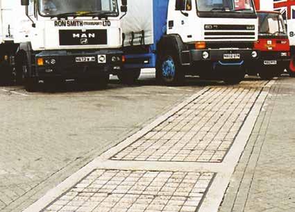
• Covers recessed for concrete infill
• Cover type DLF, DM, RRD, DM/F
To specify state:
1. Loading group
2. Pit clear opening size length (L) x span (S)
3. Cover type

Pit clear opening span (S) Cover type Standard pit clear opening length (L) 2850 2900 3000 3150 3300 3400 3550 3700 3850 3900 4000 4150 300 DLF * * * * 4 * * * * * * 5 450 RRF 4 * 4 4 4 5 5 5 5 * 5 5 600 RRD 4 3 4 4 4 5 5 5 5 4 5 5 750 RRD 4 3 4 4 4 5 5 5 5 4 5 5 900 RRD 4 3 4 4 4 5 5 5 5 4 5 5 1050 DM 4 * 4 4 4 5 5 5 5 * 5 5 1200 DM 4 * 4 4 4 5 5 5 5 * 5 5 Pit clear opening span (S) Cover type Standard pit clear opening length (L) 1300 1450 1600 1750 1900 2000 2150 2300 2450 2600 2700 2750 300 DLF * * 2 * * * * * 3 * * * 450 RRF 2 2 2 * * 3 3 3 3 * 4 * 600 RRD 2 2 2 2 2 3 3 3 3 3 4 3 750 RRD 2 2 2 2 2 3 3 3 3 3 4 3 900 RRD 2 2 2 2 2 3 3 3 3 3 4 3 1050 DM 2 2 2 * * 3 3 3 3 * 4 * 1200 DM 2 2 2 * * 3 3 3 3 * 4 * Pit clear opening sizes Cover type Suggested rebate size length x width x depth
DLF (L + 300) x 600 x 100 450 RRF (L + 400) x 850 x 125
RRD (L + 400) x 1000 x 125
RRD (L + 400) x 1150 x 125
RRD (L + 400) x 1300 x 125 1050 DM (L + 400) x 1450 x 165 1200 DM (L + 400) x 1600 x 165 1500 DM/F (L + 400) x 1900 x 165
300
600
750
900
Plan of recessed s ngle c Plan of recessed duct cover Section A - A Ch k d by D Sca e P oject T t e DO NOT SCALE Th s d aw ng and any n o mat on or desc p ve ma te set ou hereon a e con den a and he copy ght of GATIC and are not o be d sc osed oaned cop ed or used o manu ac ur ng o tende ng o or any o her pu pose without pe m ss on © 2017 Des gners nc ud ng bu not m ted o Eng neers and A ch ec s mus sa sfy hemse ves n respec o the adequacy o he des gn prov ded by GAT C s he Des gne s respons b y to ensu e hat he data has been co rect y nte pre ed GATIC accepts no ab y or nadequa e or naccu a e des gns based on im ted or a se in o mat on supp ed by the Des gne or m s nte pre a on o he data suppl ed For he avo dance of doubt des gns prov ded by GATIC pr or o an o der be ng p aced are for ust at ve pu poses only and shou d not be re ed upon save o a the Des gner s own r sk D aw ngs ssued by GAT C n respec o an orde a e tha o der has been p aced sha be for he purpose o wh ch was c eated D by R TY INCLUD P S 27 06/2019 N T S P M N A Pa No A1 Rev Rev s A FIRST ISSUE Length (L) Length (L) S p a n ( S S p a n ( S Sugested rebate l ne 1 0 0 1 2 5 S Pit c ear open ng span 200 110 10 Cover & rebates to be fi led w th 45 cube or 40 cyl nder concrete during instal at on using 10mm coarse aggregate 7 5 Ful height webs Suggested rebate line Plan of recessed cover Recessed duct covers and frames Power stations, Carriageways, hard shoulders, and parking areas for all types of vehicle Type DM / DM/F Type RRD / RRF
Types Type DLF 75 57 100 110 10 150 S Pit clear opening span Full height webs Cover & rebates to be filled with 45 cube or 40 cylinder concrete during installation using 100 coard aggregate 140 84 165 100 10 200 S Pit clear opening span Full height webs Cover & rebates to be filled with 45 cube or 40 cylinder concrete during installation using 100 coard aggregate Full height webs Pit clear opening span Section A-A 200 125 10 110 100 75 S Cover & rebates to be filled with 45 cube or 40 cylinder concrete during installation using 100 coard aggregate 47 www.alumascwms.co.uk +44 (0) 1787 475 151 Introduction Specification F900 E600 D400 C250 B125 Additional Covers/Gratings
Cover

•
•
1.

Plan of solid Plan of solid top duct cover Section A - A Checked by D Sca e DO NO Th s drawing and any in ormat on or descr pt ve matter se out hereon are conf den a e purpose wi hout permiss on © 2017 Des gners nclud ng but not lim ted to Eng neers and A ch tects mus sat s y thems been correctly in erpreted GATIC accepts no l ab ty or inadequate or inaccura e des gns based on lim ted or a se nf pp y g p pp g p y GATIC pr or to an o der be ng placed are or il ustrat ve purposes on y and shou d no be re ed upon save or at the Des gner s own r sk Drawings ssued by GATIC n respec o an orde a ter hat order has been placed shall be t fo he pu pose or wh ch it was crea ed D awn by P 27/06 2 N T S P Par No Rev A F Len Length (L) S p a n ( S ) S p a n ( S ) Sugested rebate ine 1 2 5 S Pit clear opening span 200 Rebates to be filled with 45 cube or 40 cylinder concrete during installation using 10mm coarse aggregate Solid tops covers 1 0 0 110 10 Pit clear opening span (S) Cover type Standard pit clear opening length (L) 1300 1450 1500 1600 1750 1900 2000 2150 2300 2450 2600 2700 2750 600 RSD 2 2 * 2 2 2 3 3 3 3 3 4 3 700 RSD * * 2 * * * * * 3 * * * * 750 RSD 2 2 * 2 2 2 3 3 3 3 3 4 3 900 RSD 2 2 * 2 2 2 3 3 3 3 3 4 3 1200 RSD 2 2 * 2 * * 3 3 3 3 * 4 * Pit clear opening span (S) Cover type Standard pit clear opening length (L) 2850 2900 3000 3100 3150 3300 3400 3550 3700 3850 3900 4000 4150 600 RSD 4 3 4 * 4 4 5 5 5 5 4 5 5 700 RSD * * * 4 * * * * * * 5 * * 750 RSD 4 3 4 * 4 4 5 5 5 5 4 5 5 900 RSD 4 3 4 * 4 4 5 5 5 5 4 5 5 1200 RSD 4 * 4 * 4 4 5 5 5 5 * 5 5 Pit clear opening sizes Cover type Suggested rebate size length x width x depth 600 RSD (L + 400) x 1000 x 125 700 RSD (L + 400) x 1100 x 125 750 RSD (L + 400) x 1150 x 125 900 RSD (L + 400) x 1300 x 125 1200 RSD (L + 400) x 1600 x 125
high density traffic conditions refer to page 14.
For
Covers with solid top
Cover type RSD
specify state:
To
Loading group
Pit clear opening size length (L) x span (S)
Cover type Suggested rebate line Plan of solid cover Solid top duct covers and frames Cover Types Type RSD Plan of solid top single cover Plan of solid top duct cover Section A - A Checked by Da e Sca e P o ect Tit e Draw ng Number DO NOT SCALE P C D K CT17 0UF E g a d Te ephone +44 0 1304 203545 F +44 0 1304 215001 E Ma nfo@ga c com Web www ga c com A d ALUMASC L M TED d any n o ma on o descr pt ve ma er se ou he eon are con dentia and he copyr ght o GAT C and are no to be disc osed oaned cop ed or used for manufactu ng o tender ng o for any o he purpose w hout perm ss on © 2017 d ng bu no m ted to Eng nee s and Arch ects must sa s y themse ves n espect o the adequacy of he des gn p ov ded by GATIC is the Des gne s espons b y o ensure hat the da a has been cor ect y n erpreted GAT C y or nadequa e o inaccu a e des gns based on lim ed or fa se nforma on supplied by he Des gner o m s n e pretation o the da a supp ed Fo the avo dance of doubt des gns prov ded by GAT C pr or o an o de be ng p aced purposes on y and shou d not be e ed upon save for a the Des gner s own risk Draw ngs ssued by GAT C n respec o an order af e that orde has been p aced sha be t or he purpose o wh ch t was crea ed D awn by Rev R TYPE COVERS R TYPE COVERS AND FRAME PLAN NCLUD NG SECT ON DETA LS - FOR E600 AND F900 OF BROUCHURE EG/4590 A P S 27 06/2019 N T S P M N A P N A1 Rev Revis on Date Sig A FIRST ISSUE 27/06/2019 P S Length (L) Length (L) S p a n ( S ) Sugested rebate line Sugested rebate l ne 1 2 5 S Pit c ear open ng span 200 ebates to be fi led with 45 cube or 40 cy inder oncrete during nsta lat on using 10mm coarse aggregate Sol d tops covers 1 0 0 110 10 Rebates to filled with 45 cube or 40 cylinder concrete during installation using 10mm coarse aggregate 48 www.alumascwms.co.uk +44 (0) 1787 475 151 Introduction Specification F900 E600 D400 C250 B125 Additional Covers/Gratings
2.
3.
Continuous recessed trench covers and frames
Power stations, Carriageways, hard shoulders, and parking areas for all types of vehicle
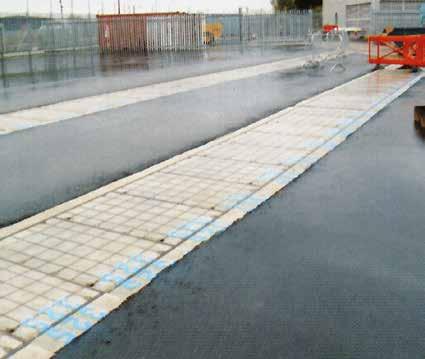
• Covers recessed for concrete infill
• Cover types: DLF, DM, RRD, DM/F
To specify state:
1. Loading group
2. Cover type
3. Supply layout drawing of trenches

*
Gatic covers can be formed to make continuous trenches or layouts providing total access to services below.
Construction drawings are required so that Gatic cover layout drawings can be prepared.

Pit clear opening span Cover type 300 DLF 450 RRF 600 RRD 750 RRD 900 RRD 1050 DM 1200 DM 1500 DM/F Continuous recessed cover
For type DM/F refer to our technical department
Type DM / DM/F Type RRD / RRF Cover Types Type DLF 75 57 100 110 10 150 S Pit clear opening span Full height webs Cover & rebates to be filled with 45 cube or 40 cylinder concrete during installation using 100 coard aggregate 140 84 165 100 10 200 S Pit clear opening span Full height webs Cover & rebates to be filled with 45 cube or 40 cylinder concrete during installation using 100 coard aggregate Full height webs Pit clear opening span Section A-A 200 125 10 110 100 75 S Cover & rebates to be filled with 45 cube or 40 cylinder concrete during installation using 100 coard aggregate 49 www.alumascwms.co.uk +44 (0) 1787 475 151 Introduction Specification F900 E600 D400 C250 B125 Additional Covers/Gratings
Continuous solid top trench covers and frames
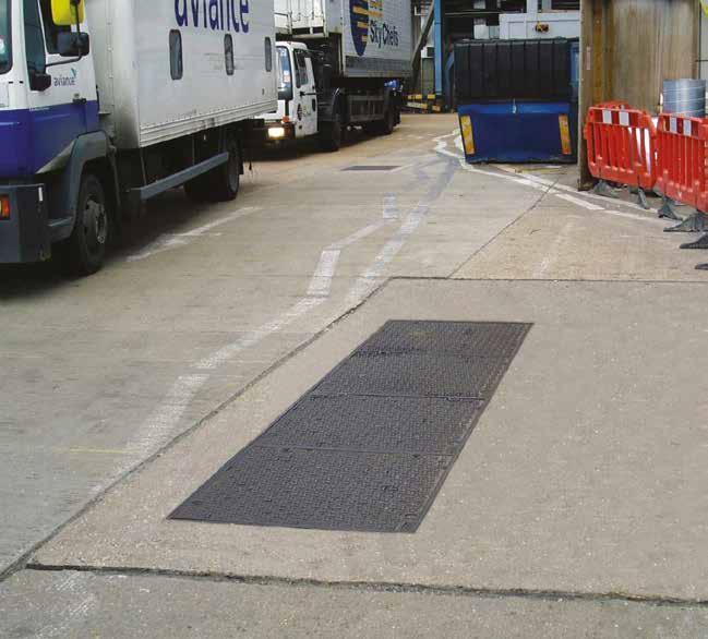
Continuous solid top cover
Standard solid top covers are supplied in straight runs. Junctions and splays can be achieved by the inclusion of localised recessed covers. Refer to our technical department for more information. For high density traffic conditions refer to page 14.
• Covers with solid top
• Cover types: RSD
To specify state:
1. Loading group
2. Cover type
3. Supply layout drawing of trenches
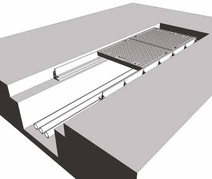
Cover Types
Pit clear opening span Cover type 600 RSD 700 RSD 750 RSD 900 RSD 1200 RSD
Type RSD Plan of solid top single cover Plan of solid top duct cover Section A - A Checked by Da e Sca e P o ect Tit e Draw ng Number DO NOT SCALE P C D K CT17 0UF E g a d Te ephone +44 0 1304 203545 F +44 0 1304 215001 E Ma nfo@ga c com Web www ga c com A d ALUMASC L M TED d any n o ma on o descr pt ve ma er se ou he eon are con dentia and he copyr ght o GAT C and are no to be disc osed oaned cop ed or used for manufactu ng o tender ng o for any o he purpose w hout perm ss on © 2017 d ng bu no m ted to Eng nee s and Arch ects must sa s y themse ves n espect o the adequacy of he des gn p ov ded by GATIC is the Des gne s espons b y o ensure hat the da a has been cor ect y n erpreted GAT C y or nadequa e o inaccu a e des gns based on lim ed or fa se nforma on supplied by he Des gner o m s n e pretation o the da a supp ed Fo the avo dance of doubt des gns prov ded by GAT C pr or o an o de be ng p aced purposes on y and shou d not be e ed upon save for a the Des gner s own risk Draw ngs ssued by GAT C n respec o an order af e that orde has been p aced sha be t or he purpose o wh ch t was crea ed D awn by Rev R TYPE COVERS R TYPE COVERS AND FRAME PLAN NCLUD NG SECT ON DETA LS - FOR E600 AND F900 OF BROUCHURE EG/4590 A P S 27 06/2019 N T S P M N A P N A1 Rev Revis on Date Sig A FIRST ISSUE 27/06/2019 P S Length (L) Length (L) S p a n ( S ) Sugested rebate line Sugested rebate l ne 1 2 5 S Pit c ear open ng span 200 ebates to be fi led with 45 cube or 40 cy inder oncrete during nsta lat on using 10mm coarse aggregate Sol d tops covers 1 0 0 110 10 Rebates to filled with 45 cube or 40 cylinder concrete during installation using 10mm coarse aggregate
stations, Carriageways, hard shoulders, and parking areas for all types of vehicle 50 www.alumascwms.co.uk +44 (0) 1787 475 151 Introduction Specification F900 E600 D400 C250 B125 Additional Covers/Gratings
Power
Multispan covers and frames
Power stations, Carriageways, hard shoulders, and parking areas for all types of vehicle
Specification
Below is a sample specification information and notes for Multispan recessed covers and frames.
For more details on features and benefits of Gatic covers, see pages 14 to 15.
Loading group Gatic D400
11.5 tonne wheel load – test load 400 kN.
Materials
Ductile iron components to BS EN 1563
Structural steel removable beams to BS EN 10365.
Finishes
Units coated with black bituminous solution for protection during transit.
Removable supporting steelwork galvanised to BS EN ISO 1461.
Infill and surround concrete by customer
Concrete strength, using 10mm down coarse aggregate, to be: 45N/mm2 for a test cube of 150mm or 40N/mm2 for a test cylinder of 150mm diameter x 300mm high.
Installation
In accordance with instructions supplied by Gatic.
To specify use size and description format as follows:
Gatic Multispan Recessed covers and frames Cover type RRD recessed Multiple access covers recessed for concrete infill with removable beams.
.... in no. .... (length) x .... (span) mm pit clear opening multi span cover and frame.

Type RRD recessed

Type RSD solid top
Gatic Type RRD Ductile Iron Recessed Cover in .... parts complete with .... in no. .... x .... mm galvanised removable support beam spanning the .... (length) mm way.
Suitable for Loading Group D400 – 11.5 Tonnes Wheel Load (pneumatic tyre).
Gatic Multispan Solid Top covers and frames Cover type RSD solid top Multiple solid top access covers with removable beams.
.... in no. .... (length) x .... (span) mm pit clear opening multi span cover and frame.
Gatic Type RSD Ductile Iron Solid Top Cover in .... parts complete with .... in no. .... x .... mm galvanised removable support beam spanning the .... (length) mm way.
Suitable for Loading Group D400 – 11.5 Tonnes Wheel Load (pneumatic tyre).
Standard pit clear opening sizes are shown on page 57.
Beam sizes and other dimensions are shown on page 58 - 59.
51 www.alumascwms.co.uk +44 (0) 1787 475 151 Introduction Specification F900 E600 D400 C250 B125 Additional Covers/Gratings
Multispan covers and frames
Product Selection
Refer to the table to identify which cover and beam configuration you require against pit clear opening length (L) and pit clear opening span (S). All dimensions are in millimetres.
1380 1530 1680 1830 1980 2160 2310 2460 2610 2760 2910 3060 3240 3090 2940 3390 3540 3690 3840 3990 4140 690 840 840 990 990 690 690 840 840 840 990 990 840 840 840 990 990 990 990 690 690 840 840 990 780 930 780 930 1080 930 1080 780 930 930 930 930 1080 1080 690 690 840 840 840 990 990 780 930 930 930 930 1080 1080 840 840 780 780 690 690 780 780 690 690 840 840 990 840 990 1300 1450 1600 1750 1900 2000 2150 2300 2450 2600 3000 2850 2700 3150 3300 3450 3600 3750 3900 Pit clear opening length (L) mm Beam centres mm Pit clear opening span (S) mm 4 parts 3 beams 3 parts 2 beams 2 parts 1 beam 2 parts 3 parts 4 parts AB CD E 2750 2900 6 part (2x3) recessed multispan cover with 2 removable support beams 9 part (3x3) recessed multispan cover with 2 removable support beams 12 part (4x3) recessed multispan cover with 2 removable support beams 8 part (2x4) recessed multispan cover with 3 removable support beams 12 part (3x4) recessed multispan cover with 3 removable support beams 16 part (4x4) recessed multispan cover with 3 removable support beams L A S B L A S B L A S B L A S B C L A S B C L A C S B L A S B C D L A S B C D L A C D S B 4020 3870 3720 4170 4320 4470 4620 4770 4920 5070 5220 690 840 840 840 990 990 990 930 930 930 930 930 930 1080 930 780 930 1080 930 1080 930 930 840 780 780 780 690 780 930 780 690 780 780 780 930 930 930 930 930 990 1080 1080 1080 1080 690 840 690 690 840 840 840 990 990 990 990 5 parts 4 beams 10 part (2x5) recessed multispan cover with 4 removable support beams 15 part (3x5) recessed multispan cover with 4 removable support beams 20 part (4x5) recessed multispan cover with 4 removable support beams L A S B C D L A S B C D L A C D E E E S B 4 part (2x2) recessed multispan cover with 1 removable support beam 6 part (3x2) recessed multispan cover with 1 removable support beam 8 part (4x2) recessed multispan cover with 1 removable support beam Note: For other pit clear opening sizes please refer to our technical department
4 part (2x2) multispan cover with 1 removable support beam
part (2x3) multispan cover with 2 removable support beam
6
cover with 3 removable support
part (2x5) multispan cover with 4 removable support beam
part
multispan cover with 1 removable support beam
8
part (2x4) multispan
beam 10
6
(3x2)
part (3x3) multispan cover with 2 removable support beam
9
part
multispan cover with 3 removable support beam
part (3x5) multispan cover with 4 removable support beam
12
(3x4)
15
cover with 1 removable support
8 part (4x2) multispan
beam
12
part (4x3) multispan cover with 2 removable support beam
part
multispan cover with 4 removable support beam
16
part (4x4) multispan cover with 3 removable support beam 20
(4x5)
52 www.alumascwms.co.uk +44 (0) 1787 475 151 Introduction Specification F900 E600 D400 C250 B125 Additional Covers/Gratings
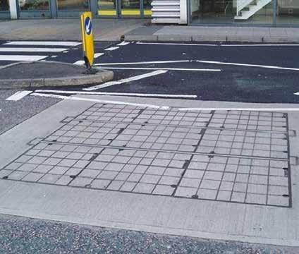
• Covers recessed for concrete infill or solid top
• Cover types: RRD (recessed) RSD (solid top)
The details below show plan and sections of a typical recessed/solid top unit.

Type
RRD recessed Type

Plan showing recessed and solid top cover options Section A - A Section B - B Section Section D A A B B C C D D eo copied or used for manufacturing or tendering or for any other purpose without permis mu t is the Designer s responsibility to ensure that the data has been correctly interpreted lim upplied For the avoidance of doubt designs provided by GATIC prior to an order bei ve for at the Designer s own risk Drawings issued by GATIC in respect of an order after that order has been placed shall be fit for the purpose for which it was created X W 1 2 5 145 20 Y L Pit clear opening length Y 1 2 5 be Recessed cover Suggested rebate for beam wallbox Suggested rebate for end frame 125 100 B A X 4 9 0 S P i t c l e a r o p e n i n g s p a n 2 0 0 1 0 1 1 0 85 Suggested rebate for side frame X W 1 2 5 1 0 0 Cover & rebates to b concrete during insta Suggested rebate for side frame Sugges rebate beam wall Recessed cover type RRF Solid top cover type RSF A B Plan showing recessed and solid top cover options Section A - A Section B - B Section C - C Section D - D A A B B C C D D Checked by Date Scale DO NO Th s draw ng and any information or descriptive matter set out hereon are confident a and the other purpose without permission © 2017 Des gners ncluding but not imited to Engineers and Architects must sat sfy themselves n r as been correctly interpreted GATIC accepts no iabi ity for inadequate or naccurate designs based on l m ted or fa se nformat on y GATIC pr or to an order being placed are for il ustrat ve purposes only and should not be re ied upon save for at the Designer s own or which t was created D awn by P 27/06/2 N T S P Part No Rev A FI X W 1 2 5 145 20 Y L Pit clear opening length Y 1 2 5 DIRECTION FOR SLIDING OUT COVER Removable support beam (supplied by Gatic) Recessed cover type RRD Solid top cover type RSD Suggested rebate for beam wallbox Suggested rebate for end frame 125 100 B A X 4 9 0 S P t c l e a r o p e n i n g s p a n 2 0 0 1 0 1 1 0 85 Suggested rebate for side frame X W DIRE b 145 20 Y 1 2 5 1 0 0 10 110 200 Cover & rebates to be filled with 45 cube or 4 concrete during installation using 10mm coa Sugge rebat beam wa Suggested rebate for side frame Suggested rebate for beam wallbox Recessed cover type RRD Solid top cover type RSD A B
RSD solid top Plan showing recessed and solid top cover options Plan showing recessed and solid top cover options Section A - A Section B - B Section C - C Section D - D A A B B C C D D Checked by Date Scale DO This drawing and any nformat on or descr ptive matter set out hereon are confidentia and the copyright of GATIC, and are not to be disclosed, oaned, cop ed or used for manufacturing or tender ng or for any other purpose without perm ss on © 2017 Designers nclud ng but not limited to Eng neers and Architects must satisfy themselves n respect of the adequacy of the des gn prov ded by GATIC It is the Des gner s responsibility to ensure that the data has been correct y nterpreted GATIC accepts no liabi ity for nadequate or inaccurate designs based on imited or false information supplied by the Designer or misinterpretation of the data suppl ed For the avoidance of doubt des gns provided by GATIC prior to an order being placed are for illustrative purposes on y and should not be re ied upon save for at the Designer s own risk Draw ngs issued by GATIC n respect of an order after that order has been p aced shall be fit for the purpose for wh ch it was created Drawn by 27/0 N T S Part No Rev A X W 1 2 5 145 20 Y L Pit clear opening length Y 1 2 5 DIRECTION FOR SLIDING OUT COVER Removable support beam (supplied by Gatic) Recessed cover type RRF Solid top cover type RSF Suggested rebate for beam wallbox Suggested rebate for end frame 125 100 B A X 4 9 0 S P i t c l e a r o p e n i n g s p a n 2 0 0 1 0 1 1 0 85 Suggested rebate for side frame X W D 145 Y 1 2 5 1 0 0 10 110 200 Cover & rebates to be filled with 45 cube o concrete during installation using 10mm c Sug reb beam w Suggested rebate for side frame Suggested rebate for beam wallbox Recessed cover type RRF Solid top cover type RSF A B RSD
For selection and specification guidance, refer to page 56. covers and frames
Multispan
53 www.alumascwms.co.uk +44 (0) 1787 475 151 Introduction Specification F900 E600 D400 C250 B125 Additional Covers/Gratings
Power stations, Carriageways, hard shoulders, and parking areas for all types of vehicle

Beam Size
The required beam size for Multispan covers is dependent on the pit clear opening length and the loading group.
The table shows maximum beam length against beam size. The removable support beams are supplied by Gatic.
The table also indicates dimensions of the beam wallbox and rebate to suit different beam sizes.
See also the accompanying section details. Support

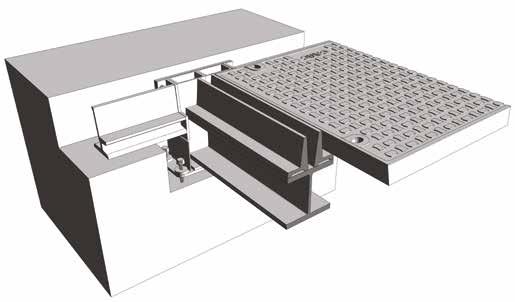
Section A - A Section C - C Section D - D A A B C C D Checked by Da e Project T tle Pou ton C ose Dover Kent CT17 0UF Eng and Te ephone +44 0) 1304 203545 Fax: +44 (0 1304 215001 E Ma n o@ga c com Web: www gatic com A d v s on o ALUMASC L MITED set out hereon are conf dential and the copyr ght of GATIC, and are not to be disclosed, loaned, copied or used for manufactur ng or tender ng or for any other purpose without permiss on © 2017 Arch tects must satisfy themse ves n respect of the adequacy of the design provided by GAT C t s the Designer s respons bil ty to ensure that the data has been correct y interpreted GATIC ns based on imited or fa se information supp ied by the Designer or misinterpretat on of the data suppl ed For the avo dance of doubt designs prov ded by GATIC prior to an order be ng p aced ed upon save for at the Designer s own risk Drawings issued by GATIC in respect of an order after that order has been placed sha l be f t for the purpose for which t was created Drawn by R TYPE COVERS R TYPE COVERS AND FRAME PLAN SECTION AND BEAM WALLBOX DETAILSP S 27/06 2019 P M Rev Revision Date Sig A FIRST ISSUE 27/06/2019 P S X W 1 2 5 145 20 Y L P t clear opening length Y 1 2 5 DIRECTION FOR SLIDING OUT COVER Removable support beam (supplied by Gatic) Recessed cover type RRD Solid top cover type RSD Suggested rebate for beam wallbox Suggested rebate for end frame P t c e a r o p e n n g s p a n X W DIRECT ON FOR SL DING OUT COVER Removable support beam (supplied by Gatic) V 145 20 Y L Pit clear opening length 1 2 5 1 0 0 10 110 200 490 X B A S Pit clear opening span Cover & rebates to be filled with 45 cube or 40 cylinder concrete during installation using 10mm coarse aggregate Full height web structure So id top cover Suggested rebate for beam wal box Suggested rebate for side frame Suggested rebate for beam wallbox Recessed cover type RRD Solid top cover type RSD A B Section C - C any other purpose without permission © 2017 ata has been correctly interpreted GATIC ed by GATIC prior to an order being p aced ose for which it was created Rev Revision Date Sig A FIRST ISSUE 27/06/2019 P S gested ate for frame X W D RECT ON FOR SLIDING OUT COVER Removable support beam (supplied by Gatic) V 145 20 Y L Pit clear opening length 5 0 0 Cover & rebates to be filled with 45 cube or 40 cylinder concrete during installation using 10mm coarse aggregate Full height web structure Solid top cover Suggested rebate for beam wallbox
beam size chart Type RSD solid top Type RRD recessed Removable support beam size Max pit clear opening length (L) Beam wallbox dimensions V W X Y 152 x 152 x 37 kg/m U.C 1750 264 286 330 230 203 x 203 x 52 kg/m U.C. 2300 308 330 370 230 305 x 165 x 54 kg/m U.B 2750 412 434 480 230 356 x 171 x 67 kg/m U.B 3150 465 487 535 300 457 x 152 x 82 kg/m U.B 3450 568 590 635 300 533 x 210 x 122 kg/m U.B 3900 647 669 715 300 Note: Removable support beams are supplied by Gatic
stations, Carriageways,
shoulders,
vehicle 54 www.alumascwms.co.uk +44 (0) 1787 475 151 Introduction Specification F900 E600 D400 C250 B125 Additional Covers/Gratings
Multispan covers and frames Power
hard
and parking areas for all types of
Pave
Gatic Pave is a comprehensive system of single, duct and multi span access covers and frames for use in paved areas where an aesthetic finish is required in environments up to D400 loading.
Cover types
Covers are recessed for an aesthetic paviour infill.
Applications
Urban public places and parking areas.
Materials
The components of Pave covers are manufactured from: Ductile iron to BS EN 1563 and structural steel sections (removable beams) to BS EN 10365.
Non-rocking
Correctly installed, Pave covers will be non-rocking under slow moving traffic.
Gas Air & Water tight
When correctly installed, Pave covers are gas, air and watertight under normal rainwater conditions.
Secure and vandal resistant
Gatic covers cannot be removed without the correct lifting key so unauthorised removal is virtually impossible. Locking bolts can be fitted to Gatic cover keyways as an additional security feature. Gatic recommends that due to their weight with paviour infill, when Pave covers are removed they are lifted vertically using Gatic’s mechanical lifting keys.
Closed keyways
Pave cover keyways are closed and fitted with plastic plugs to prevent the ingress of dirt.
Loadings
All Pave covers will withstand test load and maximum permanent set criteria specified in BS EN 124: up to D400.
Secure support
The clear opening width between supporting frames are at least 7mm greater than the pit/chamber design to allow for minor deviations in pit construction dimensions.
Beam wallbox
Supporting beams in Pave Multispan units are easily removed with appropriate lifting equipment for access to the total chamber area. Beam wallboxes do not project into the chamber opening.
Finishes:
Covers and side frames are supplied with a black bituminous paint, and all removable supporting steelwork are supplied with a galvanised finish to BS EN ISO 1461.
Installation:
Consignments of Pave units are accompanied by comprehensive installation instructions.
Gatic services:
Gatic offers a full support service to specifiers and contractors, including Computer Aided Design. AutoCAD compatible details of all Gatic products are available. Please consult our technical department for assistance.
In view of our commitment to product improvement, we reserve the right to alter designs without notice. Design changes will not adversely affect the performance or loading capability of our products.

Environmental commitment:
Responsibility towards the environment is our primary concern. Our customers often now demand products that are made from recycled and recyclable materials, supplied by companies with robust environmental policies to reduce the environmental impact of their projects for future generations.
To meet these requirements we have an integrated Quality (BS EN ISO 9001) and Environmental (BS EN ISO 14001) Management System which encompasses the design, manufacture and management systems within the company and ensures our commitment to continuous environmental improvements regarding the manufacture and design of all our products in the following ways:
• Minimise environmental impact
• Commit organisational resources to energy management
• Reduce energy costs
• Give high priority to energy efficient investments
• Consider life cycle energy costs for all new projects
• Minimise C02 emissions year on year
• Use energy from sustainable resources wherever possible
To achieve these goals we have put in place the necessary systems and controls to meet demanding environmental targets and to make sure that these are maintained for the future benefit of the environment and our customers alike.

55 www.alumascwms.co.uk +44 (0) 1787 475 151 Introduction Specification F900 E600 D400 C250 B125 Additional Covers/Gratings
Pave
Power stations, Carriageways, hard shoulders, and parking areas for all types of vehicle
Suitable for 11.5 tonne slow moving pneumatic wheel load. Cover test load - 400kN

Pave Cover s
Pave covers can be supplied to cover ducts or trenches as straight runs.
The number shown indicates the quantity of cover parts. Other cover sizes may be available. Please refer to our technical depar tment

Pit clear opening size Cover type Overall Frame Size Suggested rebate size 600 x 600 PAV 750 x 840 x 170 1000 x 1000 x 195 750 x 600 PAV 900 x 840 x 170 1150 x 1000 x 195 750 x 750 PAV 900 x 990 x 170 1150 x 1150 x 195
Pit clear opening size Cover type Suggested rebate size 600 PAV (L + 400) x 1000 x 195 750 PAV (L + 400) x 1150 x 195 Pit clear opening spans (mm) Cover type Standard Pit clear opening length 1300 1450 1600 2000 2150 2300 2450 2700 2850 3000 600 PAV 4 750 PAV Pit clear opening spans (mm) Cover type Standard Pit clear opening length 3150 3300 3400 3550 3700 4000 4100 600 PAV 750 PAV
2 4 2 4 3 5 3 5 3 5 3 5 2 4 2 4 3 5 3 5 4 6 4 6 2 5 2 5 3 5 3 5 4 4 2850 3000 4 4 3850 4150 5 5
105 16 105 16 100 170 Maximu m to sui t block depth 195 Rebate to be filled with 45 cube or 40 cylinder concrete during installation using 10mm coarse aggregate
56 www.alumascwms.co.uk +44 (0) 1787 475 151 Introduction Specification F900 E600 D400 C250 B125 Additional Covers/Gratings
Pave
Power stations, Carriageways, hard shoulders, and parking areas for all types of vehicle
Suitable for 11.5 tonne slow moving pneumatic wheel load. Cover test load - 400kN
Specification
Below is a sample specification information and notes for Multispan recessed covers and frames.
For more details on features and benefits of Gatic covers, see pages 14 to 15.
Loading group Gatic D400
11.5 tonne wheel load – test load 400 kN.
Materials
Ductile iron components to BS EN 1563
Structural steel removable beams to BS EN 10563.
Finishes
Covers and side frames are supplied with a black bituminous paint, and all removable supporting steelwork are supplied with a galvanised finish to BS EN ISO 1461.
Infill and surround concrete by customer
Concrete strength, using 10mm down coarse aggregate, to be: 45N/mm2 for a test cube of 150mm or 40N/mm2 for a test cylinder of 150mm diameter x 300mm high.
Installation
In accordance with instructions supplied by Gatic.
To specify use size and description format as follows:
Pave Multispan Recessed covers and frames Cover type Pave recessed Multiple access covers recessed for paviour infill with removable beams.
.... in no. .... (length) x .... (span) mm pit clear opening multi span cover and frame.
Pave Type Ductile Iron Recessed Cover in .... parts complete with .... in no. .... x .... mm galvanised removable support beam spanning the .... (length) mm way.
Suitable for Loading Group D400 – 11.5 Tonnes Wheel Load (pneumatic tyre).
Standard pit clear opening sizes are shown on page 65.
Beam sizes and other dimensions are shown on page 66 - 69.
For high density traffic conditions refer to page 14.
57 www.alumascwms.co.uk +44 (0) 1787 475 151 Introduction Specification F900 E600 D400 C250 B125 Additional Covers/Gratings
Pave
Product Selection
Refer to the table to identify which cover and beam configuration you require against pit clear opening length (L) and pit clear opening span (S). All dimensions are in millimetres.
Note: For other pit clear opening sizes please refer to our technical department
1380 1530 1680 2160 2310 2460 2610 69 0 84 0 84 0 69 0 69 0 84 0 84 0 84 0 84 0 84 0 69 0 69 0 84 0 78 0 93 0 78 0 93 0 78 0 93 0 93 0 69 0 69 0 84 0 84 0 78 0 93 0 93 0 84 0 84 07 80 78 06 90 69 07 80 78 06 90 69 0 84 0 1300 1450 1600 2000 2150 2300 2450 2900 2850 2700 3000 3150 3300 Pit clear opening length (L) mm Beam centres (mm) Pit clear opening span (S) mm 4 parts 3 beam 3 parts 2 beam 2 parts 1 beam 2 parts 3 parts 4 parts AB CD E 6 part (2x3) recessed multispan cover with 2 removable support beams 9 part (3x3) recessed multispan cover with 2 removable support beams 12 part (4x3) recessed multispan cover with 2 removable support beams 8 part (2x4) recessed multispan cover with 3 removable support beams 12 part (3x4) recessed multispan cover with 3 removable support beams 16 part (4x4) recessed multispan cover with 3 removable support beams L A S B L A S B L A S B L A S B C L A S B C L A C S B L A S B C D L A S B C D L A C D S B 4020 3870 3720 4170 4320 4470 69 0 84 0 84 0 93 0 93 0 93 0 93 0 78 0 93 0 93 0 84 07 80 78 07 80 69 07 80 93 07 80 69 07 80 78 07 80 93 0 93 0 69 0 84 0 69 0 69 0 84 0 84 0 5 parts 4 beam 10 part (2x5) recessed multispan cover with 4 removable support beams 15 part (3x5) recessed multispan cover with 4 removable support beams 20 part (4x5) recessed multispan cover with 4 removable support beams L A S B C D L A S B C D L A C D E E E S B
4 part (2x2) recessed multispan cover with 1 removable support beam
6 part (3x2) recessed multispan cover with 1 removable support beam
2940
3540
8 part (4x2) recessed multispan cover with 1 removable support beam
3240 3090
3390
4 part (2x2) multispan cover with 1 removable support beam
6 part (2x3) multispan cover with 2 removable support beam
8 part (2x4) multispan cover with 3 removable support beam
10 part (2x5) multispan cover with 4 removable support beam
6 part (3x2) multispan cover with 1 removable support beam
9 part (3x3) multispan cover with 2 removable support beam
12 part (3x4) multispan cover with 3 removable support beam
15 part (3x5) multispan cover with 4 removable support beam
8 part (4x2) multispan cover with 1 removable support beam
12 part (4x3) multispan cover with 2 removable support beam
16 part (4x4) multispan cover with 3 removable support beam
20 part (4x5) multispan cover with 4 removable support beam
58 www.alumascwms.co.uk +44 (0) 1787 475 151 Introduction Specification F900 E600 D400 C250 B125 Additional Covers/Gratings
Pave
Power stations, Carriageways, hard shoulders, and parking areas for all types of vehicle
Suitable for 11.5 tonne slow moving pneumatic wheel load. Cover test load - 400kN

The
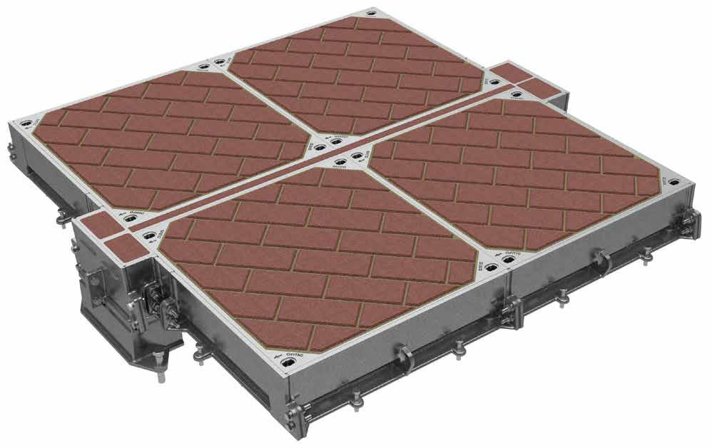
Pit Clear Opening Length (L) Section A - A Suggested rebate for end frame Y 300 165 8 6 100 W Maximu m to sui t block depth X A B B B D D C C A A Removable support beam (supplied by Gatic) Suggested rebate for beam wallbox Suggested rebate for side frame 105 1 6 200 105 1 6 200 B 530 A 100 Maximum to suit block depth Pitch Clear Opening Span (S ) Section B - B 170 Rebate to be filled with 45 cube or 40 cylinder concrete during installation using 10mm coarse aggregate 195 195
details below show a typical plan and sections of a Pave Multispan Cover.
59 www.alumascwms.co.uk +44 (0) 1787 475 151 Introduction Specification F900 E600 D400 C250 B125 Additional Covers/Gratings
Pave
Power stations, Carriageways, hard shoulders, and parking areas for all types of vehicle
Beam Size
The required beam size for Multispan covers is dependent on the pit clear opening length and the loading group. The table shows maximum beam length against beam size. The removable support beams are supplied by Gatic.
The table also indicates dimensions of the beam wallbox and rebate to suit different beam sizes. See also the accompanying section details.
Suppor t beam size char t
Lifting Keys
Gatic recommends that due to their weight with paviour infill, when Pave covers are removed they are lifted using Gatic’s Mechanical lifting keys.
A Mechanical lifting key is inserted into each of the four keyways found on all Gatic Pave covers which are designed and tested for use wih cranes and other mechanical devices
Full operating and installation instructions are available from Gatic.


Pit Clear Opening Length (L) Section C - C Y 165 8 100 W 195 Maximu m to sui t block dept h X V Suggested rebate for beam wallbox 105 16 200 B 530 A 100 Maximu m to sui t block dept h Pit Clear Opening Span (S) Section D - D 170 Rebate to be filled with 45 cube or 40 cylinder concrete during installation using 10mm coarse aggregate Suggested rebate for side frame Specified paviour infill Suggested rebate for beam wallbox 195 Removable support beam size Max pit clear opening length (L) Beam wallbox dimensions V W X Y 152 x 152 x 37 kg/m U.C 1750 297 319 365 230 203 x 203 x 52 kg/m U.C. 2300 341 363 405 230 305 x 165 x 54 kg/m U.B 2750 445 467 515 230 356 x 171 x 67 kg/m U.B 3150 498 520 570 300 457 x 152 x 82 kg/m U.B 3450 601 623 670 300 533 x 210 x 122 kg/m U.B 3900 680 702 750 300
60 www.alumascwms.co.uk +44 (0) 1787 475 151 Introduction Specification F900 E600 D400 C250 B125 Additional Covers/Gratings
Pave
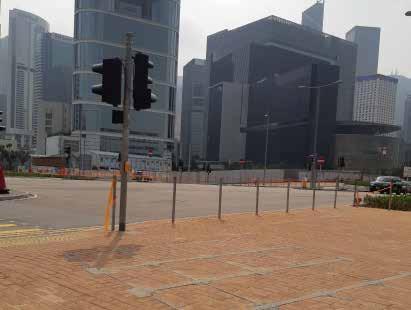




61 www.alumascwms.co.uk +44 (0) 1787 475 151 Introduction Specification F900 E600 D400 C250 B125 Additional Covers/Gratings

C250
62 www.alumascwms.co.uk +44 (0) 1787 475 151 Introduction Specification F900 E600 D400 C250 B125 Additional Covers/Gratings
Loading group C250 introduction
For roads carrying relatively slow-moving traffic eg, minor residential roads, cul-de-sacs, pedestrian precincts, yards, etc
This section includes Gatic covers and frames designed for Loading Group C250.
5 tonne wheel load, test load 250kN – Suitable for:
• Minor residential roads
• Cul-de-sacs
• Pedestrian precincts
• Yards, etc


C250 assemblies are available with a choice of cover designs – recessed or solid top.
Recessed for concrete infill:
Recessed covers are available in a choice of designs designated by a ‘Type’ reference. C250 recessed covers are available as Type DLF, DM and DM/F. Section drawings of the different recessed cover types are shown on the following pages.

Solid top:
Solid top cover types are lighter in weight than recessed covers, and feature an anti-slip surface. Solid top covers are denoted by the code Type DLS and RSD depicted in section on the following pages.

Cover Types


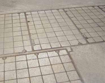

If you are uncertain as to the adequacy of covers conforming to a particular loading, we recommend specifying covers in a higher loading group. For example, if in doubt about covers in Loading Group C250, we recommend you specify covers in Loading Group D400.
Single covers and frames
Duct covers and frames
Continuous trench covers and frames
Multispan covers and frames
63 www.alumascwms.co.uk +44 (0) 1787 475 151 Introduction Specification F900 E600 D400 C250 B125 Additional Covers/Gratings
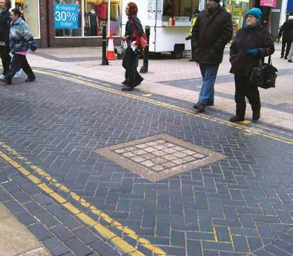
• Covers recessed for concrete infill
• Cover types: DLF, DM, RRF, DM/F
To specify state:
1. Loading group
2. Pit clear opening size length (L) x span (S)
3. Cover type

Length (L) Span (S) Sugested rebate line Pit clear opening sizes L x S Cover type Overall frame size length x width x depth Suggested rebate size length x width x depth 750 x 300 DLF 900 x 540 x 75 1050 x 600 x 100 600 x 450 RRF 750 x 690 x 100 900 x 750 x 125 750 x 450 RRF 900 x 670 x 100 1150 x 850 x 125 600 x 600 DLF 770 x 840 x 75 900 x 900 x 100 750 x 600 DLF 920 x 840 x 75 1050 x 900 x 100 900 x 600 DLF 1070 x 840 x 75 1200 x 900 x 100 750 x 750 DLF 920 x 990 x 75 1050 x 1050 x 100 900 x 750 DLF 1070 x 990 x 75 1200 x 1050 x 100 900 x 900 DLF 1120 x 1140 x 75 1200 x 1200 x 100 600 x 1050 DM 820 x 1270 x 140 1000 x 1450 x 165 750 x 1050 DM 970 x 1270 x 140 1150 x 1450 x 165 1000 x 1050 DM 1220 x 1270 x 140 1400 x 1450 x 165 600 x 1200 DM 820 x 1420 x 140 1000 x 1600 x 165 750 x 1200 DM 970 x 1420 x 140 1150 x 1600 x 165 600 x 1500 DM/F 820 x 1720 x 140 1000 x 1900 x 165 750 x 1500 DM/F 970 x 1720 x 140 1150 x 1900 x 165 Suggested rebate line Plan of recessed cover Single recessed covers and frames Type DM / DM/F Type DLF Type RRF Cover Types For roads carrying relatively slow-moving traffic eg, minor residential roads, cul-de-sacs, pedestrian precincts, yards, etc 75 57 100 110 10 150 S Pit clear opening span Full height webs Cover & rebates to be filled with 45 cube or 40 cylinder concrete during installation using 100 coard aggregate 140 84 165 100 10 200 S Pit clear opening span Full height webs Cover & rebates to be filled with 45 cube or 40 cylinder concrete during installation using 100 coard aggregate Full height webs Pit clear opening span Section A-A 200 125 10 110 100 75 S Cover & rebates to be filled with 45 cube or 40 cylinder concrete during installation using 100 coard aggregate 64 www.alumascwms.co.uk +44 (0) 1787 475 151 Introduction Specification F900 E600 D400 C250 B125 Additional Covers/Gratings
For roads carrying relatively slow-moving traffic eg, minor residential roads, cul-de-sacs, pedestrian precincts, yards, etc
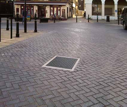
• Covers with solid top
• Cover types: DLS, RSD
To specify state:
1. Loading group
2. Pit clear opening size length (L) x span (S)
3. Cover type

Cover Types
Length (L) Span (S) Sugested rebate line Pit clear opening sizes L x S Cover type Overall frame size length x width x depth Suggested rebate size length x width x depth 600 x 600 DLS 770 x 840 x 75 900 x 900 x 100 750 x 600 DLS 920 x 840 x 75 1050 x 900 x 100 900 x 600 DLS 1070 x 840 x 75 1200 x 900 x 100 750 x 750 DLS 920 x 990 x 75 1050 x 1050 x 100 900 x 750 DLS 1070 x 990 x 75 1200 x 1050 x 100 900 x 900 DLS 1120 x 1040 x 75 1200 x 1200 x 100 600 x 1200 RSD 750 x 1420 x 100 1000 x 1600 x 125 750 x 1200 RSD 900 x 1420 x 100 1150 x 1600 x 125 1000 x 1000 RSD 1220 x 1240 x 100 1400 x 1400 x 125 Suggested rebate line Plan of solid cover
solid top covers and frames
Single
Type RSD Type DLS Plan of solid top single cover Plan of solid top duct cover Section A - A Checked by Da e Sca e P o ect Tit e Draw ng Number DO NOT SCALE P C D K CT17 0UF E g a d Te ephone +44 0 1304 203545 F +44 0 1304 215001 E Ma nfo@ga c com Web www ga c com A d ALUMASC L M TED d any n o ma on o descr pt ve ma er se ou he eon are con dentia and he copyr ght o GAT C and are no to be disc osed oaned cop ed or used for manufactu ng o tender ng o for any o he purpose w hout perm ss on © 2017 d ng bu no m ted to Eng nee s and Arch ects must sa s y themse ves n espect o the adequacy of he des gn p ov ded by GATIC is the Des gne s espons b y o ensure hat the da a has been cor ect y n erpreted GAT C y or nadequa e o inaccu a e des gns based on lim ed or fa se nforma on supplied by he Des gner o m s n e pretation o the da a supp ed Fo the avo dance of doubt des gns prov ded by GAT C pr or o an o de be ng p aced purposes on y and shou d not be e ed upon save for a the Des gner s own risk Draw ngs ssued by GAT C n respec o an order af e that orde has been p aced sha be t or he purpose o wh ch t was crea ed D awn by Rev R TYPE COVERS R TYPE COVERS AND FRAME PLAN NCLUD NG SECT ON DETA LS - FOR E600 AND F900 OF BROUCHURE EG/4590 A P S 27 06/2019 N T S P M N A P N A1 Rev Revis on Date Sig A FIRST ISSUE 27/06/2019 P S Length (L) Length (L) S p a n ( S ) Sugested rebate line Sugested rebate l ne 1 2 5 S Pit c ear open ng span 200 ebates to be fi led with 45 cube or 40 cy inder oncrete during nsta lat on using 10mm coarse aggregate Sol d tops covers 1 0 0 110 10 Rebates to filled with 45 cube or 40 cylinder concrete during installation using 10mm coarse aggregate Rebates to be filled with 45 cube or 40 cylinder concrete during installation using 10mm coarse aggregate 75 100 110 10 150 S Pit clear opening span Solid top covers 140 165 100 10 200 S Pit clear opening span Solid top covers
65 www.alumascwms.co.uk +44 (0) 1787 475 151 Introduction Specification F900 E600 D400 C250 B125 Additional Covers/Gratings
Recessed duct covers & frames
For roads carrying relatively slow-moving traffic eg, minor residential roads, cul-de-sacs, pedestrian precincts, yards, etc

• Covers recessed for concrete infill
• Cover types: DLF, DM, DM/F
To specify state:
1. Loading group
2. Pit clear opening size length (L) x span (S)
3. Cover type

Pit clear opening span (S) Cover type Standard pit clear opening length (L) 2850 2900 3000 3150 3300 3400 3550 3700 3850 3900 4000 4150 300 DLF * * * * 4 * * * * * * 5 450 RRF * * * * * 5 * * * * * * 600 DLF 4 3 4 4 4 5 5 5 5 4 5 5 750 DLF 4 3 4 4 4 5 5 5 5 4 5 5 900 DLF 4 3 4 4 4 5 5 5 5 4 5 5 1050 DM 4 * 4 4 4 5 5 5 5 * 5 5 1200 DM 4 * 4 4 4 5 5 5 5 * 5 5 1500 DM/F 4 * 4 4 4 5 5 5 5 * 5 5 Pit clear opening span (S) Cover type Standard pit clear opening length (L) 1300 1450 1600 1750 1900 2000 2150 2300 2450 2600 2700 2750 300 DLF * * 2 * * * * * 3 * * * 450 RRF 2 * * * * 3 * * * * 4 * 600 DLF 2 2 2 2 2 3 3 3 3 3 4 3 750 DLF 2 2 2 2 2 3 3 3 3 3 4 3 900 DLF 2 2 2 2 2 3 3 3 3 3 4 3 1050 DM 2 2 2 * * 3 3 3 3 * 4 * 1200 DM 2 2 2 * * 3 3 3 3 * 4 * 1500 DM/F 2 2 2 * * 3 3 3 3 * 4 * Pit clear opening sizes Cover type Suggested rebate size length x width x depth
DLF (L + 300) x 600 x 100 450 RRF (L + 400) x 850 x 125 600 DLF (L + 300) x 900 x 100 750 DLF (L + 300) x 1050 x 100 900 DLF (L + 300) x 1200 x 100 1050 DM (L + 400) x 1450 x 165 1200 DM (L + 400) x 1600 x 165 1500 DM/F (L + 400) x 1900 x 165 Length (L) Span (S) Sugested rebate line
300
Suggested rebate line Plan of recessed cover
Type DM / DM/F Type DLF Type RRF
Types 75 57 100 110 10 150 S Pit clear opening span Full height webs Cover & rebates to be filled with 45 cube or 40 cylinder concrete during installation using 100 coard aggregate 140 84 165 100 10 200 S Pit clear opening span Full height webs Cover & rebates to be filled with 45 cube or 40 cylinder concrete during installation using 100 coard aggregate Full height webs Pit clear opening span Section A-A 200 125 10 110 100 75 S Cover & rebates to be filled with 45 cube or 40 cylinder concrete during installation using 100 coard aggregate 66 www.alumascwms.co.uk +44 (0) 1787 475 151 Introduction Specification F900 E600 D400 C250 B125 Additional Covers/Gratings
Cover
For roads carrying relatively slow-moving traffic eg, minor residential roads, cul-de-sacs, pedestrian precincts, yards, etc

• Covers with solid top
• Cover types: DLS, RSD
To specify state:
1. Loading group
2.
3. Cover type

Pit clear opening span (S) Cover type Standard pit clear opening length (L) 2850 2900 3000 3150 3300 3400 3550 3700 3850 3900 4000 4150 600 DLS 4 3 4 4 4 5 5 5 5 4 5 5 750 DLS 4 3 4 4 4 5 5 5 5 4 5 5 900 DLS 4 3 4 4 4 5 5 5 5 4 5 5 1200 RSD 4 * 4 4 4 5 5 5 5 * 5 5 Pit clear opening span (S) Cover type Standard pit clear opening length (L) 1300 1450 1600 1750 1900 2000 2150 2300 2450 2600 2700 2750 600 DLS 2 2 2 2 2 3 3 3 3 3 4 3 750 DLS 2 2 2 2 2 3 3 3 3 3 4 3 900 DLS 2 2 2 2 2 3 3 3 3 3 4 3 1200 RSD 2 2 2 * * 3 3 3 3 * 4 * Pit clear opening sizes Cover type Suggested rebate size length x width x depth 600 DLS (L + 300) x 900 x 100 750 DLS (L + 300) x 1050 x 100 900 DLS (L + 300) x 1200 x 100 1200 RSD (L + 400) x 1600 x 125 Length (L) Span (S) Sugested rebate line
Pit clear opening size length (L) x span (S)
* Indicates standard sizes not available The number shown indicates the quantity of cover parts Other standard sizes may be available, refer to our technical department Suggested rebate line Plan of solid cover
top
Solid
covers and frames
Type RSD Type DLS Plan of solid top single cover Plan of solid top duct cover Section A - A Checked by Da e Sca e P o ect Tit e Draw ng Number DO NOT SCALE P C D K CT17 0UF E g a d Te ephone +44 0 1304 203545 F +44 0 1304 215001 E Ma nfo@ga c com Web www ga c com A d ALUMASC L M TED d any n o ma on o descr pt ve ma er se ou he eon are con dentia and he copyr ght o GAT C and are no to be disc osed oaned cop ed or used for manufactu ng o tender ng o for any o he purpose w hout perm ss on © 2017 d ng bu no m ted to Eng nee s and Arch ects must sa s y themse ves n espect o the adequacy of he des gn p ov ded by GATIC is the Des gne s espons b y o ensure hat the da a has been cor ect y n erpreted GAT C y or nadequa e o inaccu a e des gns based on lim ed or fa se nforma on supplied by he Des gner o m s n e pretation o the da a supp ed Fo the avo dance of doubt des gns prov ded by GAT C pr or o an o de be ng p aced purposes on y and shou d not be e ed upon save for a the Des gner s own risk Draw ngs ssued by GAT C n respec o an order af e that orde has been p aced sha be t or he purpose o wh ch t was crea ed D awn by Rev R TYPE COVERS R TYPE COVERS AND FRAME PLAN NCLUD NG SECT ON DETA LS - FOR E600 AND F900 OF BROUCHURE EG/4590 A P S 27 06/2019 N T S P M N A P N A1 Rev Revis on Date Sig A FIRST ISSUE 27/06/2019 P S Length (L) Length (L) S p a n ( S ) Sugested rebate line Sugested rebate l ne 1 2 5 S Pit c ear open ng span 200 ebates to be fi led with 45 cube or 40 cy inder oncrete during nsta lat on using 10mm coarse aggregate Sol d tops covers 1 0 0 110 10 Rebates to filled with 45 cube or 40 cylinder concrete during installation using 10mm coarse aggregate Rebates to be filled with 45 cube or 40 cylinder concrete during installation using 10mm coarse aggregate 75 100 110 10 150 S Pit clear opening span Solid top covers 140 165 100 10 200 S Pit clear opening span Solid top covers
Cover Types
67 www.alumascwms.co.uk +44 (0) 1787 475 151 Introduction Specification F900 E600 D400 C250 B125 Additional Covers/Gratings
Continuous recessed cover and frames
For roads carrying relatively slow-moving traffic eg, minor residential roads, cul-de-sacs, pedestrian precincts, yards, etc

• Covers recessed for concrete infill
• Cover type DLF, DM, DM/F
To specify state:
1. Loading group
2. Cover type
3. Supply layout drawing of trenches


Gatic covers can be formed to make continuous trenches or layouts
total
to services below.
Construction drawings are required so that Gatic cover layout drawings can be prepared.
Cover Types
Pit clear opening span Cover type 300 DLF 450 RRF 600 DLF 750 DLF 900 DLF 1050 DM 1200 DM 1500 DM/F Continuous recessed cover Note: type DM/F refer to our technical department
providing
access
Type DM / DM/F 75 57 100 110 10 150 S Pit clear opening span Covers and r ebates to be filled with 45 cube or 40 cylinder conc re te during installation using 10mm coarse aggr egat e Full height webs 140 84 165 100 10 200 S Pit clear opening span Full height webs 140 84 165 100 10 200 S Pit clear opening span Full height webs Type DLF
68 www.alumascwms.co.uk +44 (0) 1787 475 151 Introduction Specification F900 E600 D400 C250 B125 Additional Covers/Gratings
For roads carrying relatively slow-moving traffic eg, minor residential roads, cul-de-sacs, pedestrian precincts, yards, etc

Standard solid top covers are supplied in straight runs. Junctions and splays can be achieved by the inclusion of localised recessed covers. Refer to our technical department for more information.
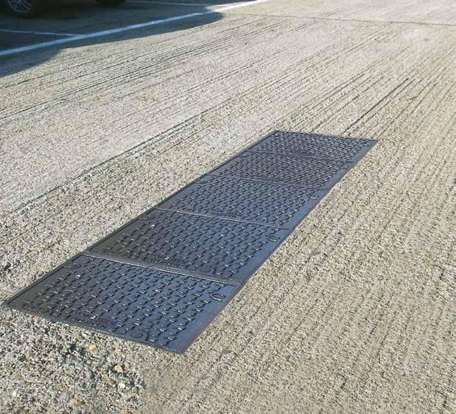
Pit clear opening span Cover type 600 DLS 750 DLS 900 DLS 1200 RSD Continuous solid top cover terminations Pit clear opening length L Overall end plate L + 150 S S Rebate line Rebate line L End terminations Pit clear opening length Overall end plate L Direction of sliding out covers Direction of sliding out covers Direction of sliding out covers Direction of sliding out covers
• Covers with solid top • Cover type DLS, RSD To specify state: 1. Loading group 2. Cover type 3. Supply layout drawing of trenchs Continuous solid top covers and frames Cover Types Type RSD Type DLS Plan of solid top single cover Plan of solid top duct cover Section A - A Checked by Da e Sca e P o ect Tit e Draw ng Number DO NOT SCALE P C D K CT17 0UF E g a d Te ephone +44 0 1304 203545 F +44 0 1304 215001 E Ma nfo@ga c com Web www ga c com A d ALUMASC L M TED d any n o ma on o descr pt ve ma er se ou he eon are con dentia and he copyr ght o GAT C and are no to be disc osed oaned cop ed or used for manufactu ng o tender ng o for any o he purpose w hout perm d ng bu no m ted to Eng nee s and Arch ects must sa s y themse ves n espect o the adequacy of he des gn p ov ded by GATIC is the Des gne s espons b y o ensure hat the da a has been cor ect y n erprete y or nadequa e o inaccu a e des gns based on lim ed or fa se nforma on supplied by he Des gner o m s n e pretation o the da a supp ed Fo the avo dance of doubt des gns prov ded by GAT C pr or o an o de b purposes on y and shou d not be e ed upon save for a the Des gner s own risk Draw ngs ssued by GAT C n respec o an order af e that orde has been p aced sha be t or he purpose o wh ch t was crea ed D awn by Rev R TYPE COVERS R TYPE COVERS AND FRAME PLAN NCLUD NG SECT ON DETA LS - FOR E600 AND F900 OF BROUCHURE EG/4590 A P S 27 06/2019 N T S P M N A P N A1 Length (L) Length (L) S p a n ( S ) Sugested rebate line Sugested rebate l ne 1 2 5 S Pit c ear open ng span 200 ebates to be fi led with 45 cube or 40 cy inder oncrete during nsta lat on using 10mm coarse aggregate Sol d tops covers 1 0 0 110 10 Rebates to filled with 45 cube or 40 cylinder concrete during installation using 10mm coarse aggregate Rebates to be filled with 45 cube or 40 cylinder concrete during installation using 10mm coarse aggregate 75 100 110 10 150 S Pit clear opening span Solid top covers 140 165 100 10 200 S Pit clear opening span Solid top covers
69 www.alumascwms.co.uk +44 (0) 1787 475 151 Introduction Specification F900 E600 D400 C250 B125 Additional Covers/Gratings
Multispan covers & frames
For roads carrying relatively slow-moving traffic eg, minor residential roads, cul-de-sacs, pedestrian precincts, yards, etc
Specification
Below is a sample specification information and notes for Multispan recessed covers and frames.
For more details on features and benefits of Gatic covers, see pages 14 to 15.
Loading group Gatic C250
5 tonne wheel load – test load 250 kN.
Materials
Ductile iron components to BS EN 1563.
Structural steel removable beams to BS EN 10365.
Finishes
Units coated with black bituminous solution for protection during transit.
Removable supporting steelwork galvanised to BS EN ISO 1461.
Infill and surround concrete by customer
Concrete strength, using 10mm down coarse aggregate, to be: 45N/mm2 for a test cube of 150mm or 40N/mm2 for a test cylinder of 150mm diameter x 300mm high.
Installation
In accordance with instructions supplied by Gatic.

DLF recessed

To specify use size and description format as follows:
Gatic Multispan Recessed covers and frames Cover type DLF recessed Multiple access covers recessed for concrete infill with removable beams.
.... in no. .... (length) x .... (span) mm pit clear opening multi span cover and frame. Gatic Type DLF Ductile Iron
Recessed Cover in .... parts complete with .... in no. .... x .... mm galvanised removable support beam spanning the .... (length) mm way.
Suitable for Loading Group C250 – Medium Duty 5 Tonnes Wheel Load (pneumatic tyre).
Gatic Multispan Solid Top covers and frames Cover type DLS solid top Multiple solid top access covers with removable beams.
.... in no. .... (length) x .... (span) mm pit clear opening multi span cover and frame. Gatic Type DLS Ductile Iron Solid Top Cover in .... parts complete with .... in no. .... x .... mm galvanised removable support beam spanning the .... (length) mm way.
Suitable for Loading Group C250 – Medium Duty 5 Tonnes Wheel Load (pneumatic tyre).
Standard pit clear opening sizes are shown on page 79.
Beam sizes and other dimensions are shown on page 80 - 81
For high density traffic conditions refer to page 14.
Type DLS solid top
Type
70 www.alumascwms.co.uk +44 (0) 1787 475 151 Introduction Specification F900 E600 D400 C250 B125 Additional Covers/Gratings
Multispan covers & frames
Product Selection
Refer to the table to identify which cover and beam configuration you require against pit clear opening length (L) and pit clear opening span (S). All dimensions are in millimetres.
1380 1530 1680 1830 1980 2160 2310 2460 2610 2760 2910 3060 3240 3090 2940 3390 3540 3690 3840 3990 4140 690 840 840 990 990 690 690 840 840 840 990 990 840 840 840 990 990 990 990 690 690 840 840 990 780 930 780 930 1080 930 1080 780 930 930 930 930 1080 1080 690 690 840 840 840 990 990 780 930 930 930 930 1080 1080 840 840 780 780 690 690 780 780 690 690 840 840 990 840 990 1300 1450 1600 1750 1900 2000 2150 2300 2450 2600 3000 2850 2700 3150 3300 3450 3600 3750 3900 Pit clear opening length (L) mm Beam centres mm Pit clear opening span (S) mm 4 parts 3 beams 3 parts 2 beams 2 parts 1 beam 2 parts 3 parts 4 parts AB CD E 2750 2900 6 part (2x3) recessed multispan cover with 2 removable support beams 9 part (3x3) recessed multispan cover with 2 removable support beams 12 part (4x3) recessed multispan cover with 2 removable support beams 8 part (2x4) recessed multispan cover with 3 removable support beams 12 part (3x4) recessed multispan cover with 3 removable support beams 16 part (4x4) recessed multispan cover with 3 removable support beams L A S B L A S B L A S B L A S B C L A S B C L A C S B L A S B C D L A S B C D L A C D S B 4020 3870 3720 4170 4320 4470 4620 4770 4920 5070 5220 690 840 840 840 990 990 990 930 930 930 930 930 930 1080 930 780 930 1080 930 1080 930 930 840 780 780 780 690 780 930 780 690 780 780 780 930 930 930 930 930 990 1080 1080 1080 1080 690 840 690 690 840 840 840 990 990 990 990 5 parts 4 beams
part (2x5) recessed multispan cover with 4 removable support beams 15 part (3x5) recessed multispan cover with 4 removable support beams
part (4x5)
L A S B C D L A S B C D L A C D E E E S B
10
20
recessed multispan cover with 4 removable support beams
part
cover with 1 removable support beam
part (3x2) recessed multispan cover with 1 removable support beam
part (4x2) recessed
cover
1 removable support beam
4
(2x2) recessed multispan
6
8
multispan
with
part
cover with 1 removable support beam
4
(2x2) multispan
part
beam
6
(2x3) multispan cover with 2 removable support
part
8
(2x4) multispan cover with 3 removable
support beam
10 part (2x5) multispan cover with 4 removable support beam
6 part (3x2) multispan cover with 1 removable support beam
9 part (3x3) multispan cover with 2 removable support beam
12 part (3x4) multispan cover with 3 removable support beam
15 part (3x5) multispan cover with 4 removable support beam
8 part (4x2) multispan cover with 1 removable support beam
12 part (4x3) multispan cover with 2 removable support beam
16 part (4x4) multispan cover with 3 removable support beam
20 part (4x5) multispan cover with 4 removable support beam
71 www.alumascwms.co.uk +44 (0) 1787 475 151 Introduction Specification F900 E600 D400 C250 B125 Additional Covers/Gratings
Multispan covers & frames
For roads carrying relatively slow-moving traffic eg, minor residential roads, cul-de-sacs, pedestrian precincts, yards, etc

• Covers recessed for concrete infill or solid top
• Cover types: DLF` (recessed) DLS (solid top)
The details below show plan and sections of a typical recessed/solid top unit. For selection and specification guidance, refer to page 78.


110 X 150 100 10 230 L W 100 v Pit clear opening length Recessed cover type DLF Direction of sliding out covers Section A - A 230 A C B B D D A B X S Pit clear opening span 100 150 75 10 57 Section B - B A C A B 43 0 Suggested rebate for end frame Suggested rebate for beam wallbox Suggested rebate for side frame Solid top cover type DLS Recessed cover type DLF Solid top cover type DLS Removable support beam (supplied by Gatic) Type DLF recessed Type DLS solid top
72 www.alumascwms.co.uk +44 (0) 1787 475 151 Introduction Specification F900 E600 D400 C250 B125 Additional Covers/Gratings
Multispan covers & frames
For roads carrying relatively slow-moving traffic eg, minor residential roads, cul-de-sacs, pedestrian precincts, yards, etc

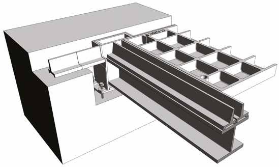
Beam Size
The required beam size for Multispan covers is dependent on the pit clear opening length and the loading group. The table shows maximum beam length against beam size. The removable support beams are supplied by Gatic. The table also indicates dimensions of the beam wallbox and rebate to suit different beam sizes. See also the accompanying section details.

Support beam size chart 110 X 100 230 W 100 Recessed cover type DLF Section A - A A C B D D A B X S Pit clear opening span 100 150 75 10 57 Section B - B 100 X W 230 10 150 L Pit clear opening length Section C - C Section D - D V Direction of sliding out covers 10 110 75 S 430 A B 150 100 X Pit clear opening span Covers & rebates to be filled with 45 cube or 40 cylinder concrete during installation using 10mm coarse aggregate Full height web Solid top cover A C A B 43 0 Suggested rebate for end frame Suggested rebate for beam wallbox Suggested rebate for side frame Suggested rebate for beam wallbox Suggested rebate for side frame Suggested rebate for beam wallbox Solid top cover type DLS Solid top cover type DLS Removable support beam (supplied by Gatic) Type DLS solid top Type DLF recessed Note: Removable support beams are supplied by Gatic Removable support beam size Max pit clear opening length (L) Beam wallbox dimensions V W X Y 152 x 152 x 37 kg/m U.C 2450 237 259 300 230 203 x 203 x 52 kg/m U.C. 3150 281 303 345 230 305 x 165 x 54 kg/m U.B 3750 385 407 450 230 356 x 171 x 67 kg/m U.B 3900 438 460 505 230
73 www.alumascwms.co.uk +44 (0) 1787 475 151 Introduction Specification F900 E600 D400 C250 B125 Additional Covers/Gratings
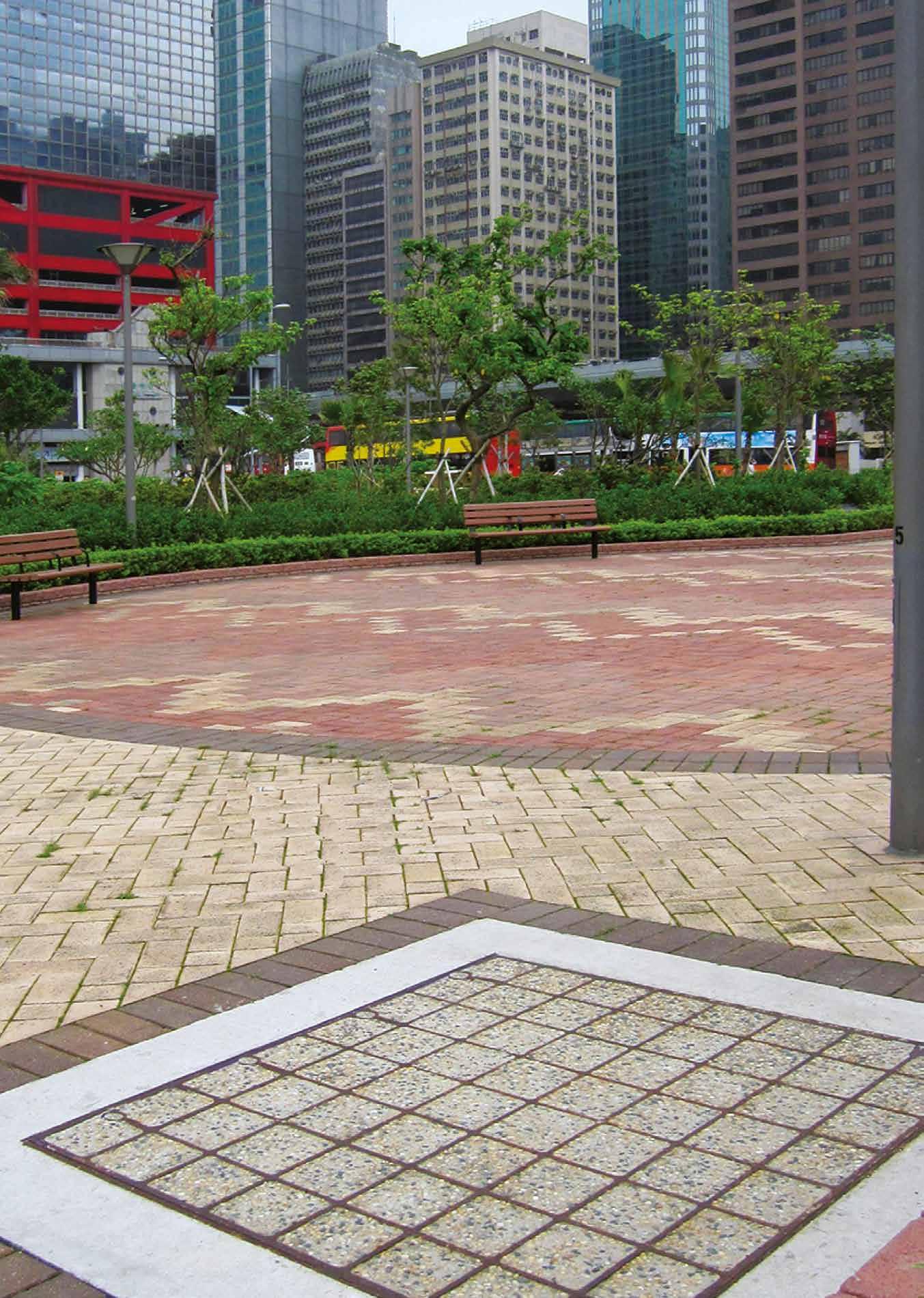
Introduction Specification F900 E600 D400 C250 B125 Additional Covers/Gratings
Introduction
Footways, pedestrian areas, car parks, driveways and internal floors
3 tonne wheel load, test load
125kN – Suitable for:
• Footways
• Pedestrian areas
• Car parks
• Driveways
• Internal floors
B125 assemblies are available with a choice of cover designs – recessed or solid top.
Recessed for concrete infill
Recessed covers are available in a choice of designs designated by a ‘Type’ reference. B125 recessed covers are available as Type DL, DLF and DM/F. Section drawings of the different recessed cover types are shown on the following pages.

Solid top
Solid top cover types are lighter in weight than recessed covers, and feature an anti-slip surface. Solid top covers are denoted by the code Type DLS and RSD depicted in section on the following pages.


If you are uncertain as to the adequacy of covers conforming to a particular loading, we recommend specifying covers in a higher loading group. For example, if in doubt about covers in Loading Group B125, we recommend you specify covers in Loading Group C250.
 Single covers and frames
Duct covers and frames
Continuous trench covers & frames
Multispan covers and frames
Range
75 www.alumascwms.co.uk +44 (0) 1787 475 151 Introduction Specification F900 E600 D400 C250 B125 Additional Covers/Gratings
Footways, pedestrian areas, car parks, driveways and internal floors

• Covers recessed for concrete infill
• Cover types: DLF, DL, DM, DM/F
To specify state:
1. Loading group
2. Pit clear opening size length (L) x span (S)
3. Cover type

600
Cover Types
Pit clear opening sizes Cover type Overall frame size length x width x depth Suggested rebate size length x width x depth
x 300 DLF 900 x 540 x 75 1050 x 600 x 100
x 450 RRF 750 x 690 x 100 1000 x 850 x 125
x 450 RRF 900 x 690 x 100 1150 x 850 x 125
750
600
750
x 600 DLF 770 x 840 x 75 900 x 900 x 100
x 600 DLF 920 x 840 x 75 1050 x 900 x 100
x 600 DLF 1070 x 840 x 75 1200 x 900 x 100 750 x 750 DLF 920 x 990 x 75 1050 x 1050 x 100
x 750 DLF 1070 x 990 x 75 1200 x 1050 x 100
x 900 DLF 1120 x 1140 x 75 1200 x 1200 x 100
x 1050 DL 850 x 1290 x 75 900 x 1350 x 100
x 1050 DL 1000 x 1290 x 75 1050 x 1350 x 100
x 1050 DM 1220 x 1270 x 140 1400 x 1450 x 165
x 1200 DM 820 x 1420 x 140 1000 x 1600 x 165
x 1200 DM 970 x 1420 x 140 1150 x 1600 x 165 600 x 1500 DM/F 820 x 1720 x 140 1000 x 1900 x 165 750 x 1500 DM/F 970 x 1720 x 140 1150 x 1900 x 165
750
900
900
900
600
750
1000
600
750
Length (L) Span (S) Sugested rebate line Suggested rebate line Plan of recessed cover
recessed covers and frames
Single
Type DM / DM/F Type DLF Type RRF Type DL 75 57 100 110 10 150 S Pit clear opening span Full height webs Cover & rebates to be filled with 45 cube or 40 cylinder concrete during installation using 100 coard aggregate 140 84 165 100 10 200 S Pit clear opening span Full height webs Cover & rebates to be filled with 45 cube or 40 cylinder concrete during installation using 100 coard aggregate Full height webs Pit clear opening span Section A-A 200 125 10 110 100 75 S Cover & rebates to be filled with 45 cube or 40 cylinder concrete during installation using 100 coard aggregate 57 100 110 10 150 S Pit clear opening span 75 Cover & rebates to be filled with 45 cube or 40 cylinder concrete during installation using 100 coard aggregate Webs reduced by 23mm 76 www.alumascwms.co.uk +44 (0) 1787 475 151 Introduction Specification F900 E600 D400 C250 B125 Additional Covers/Gratings
Footways, pedestrian areas, car parks, driveways and internal floors

1.
2.
3.
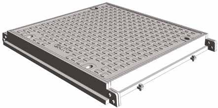
Pit clear opening sizes Cover type Overall frame size length x width x depth Suggested rebate size length x width x depth 600 x 600 DLS 770 x 840 x 75 900 x 900 x 100 750 x 600 DLS 920 x 840 x 75 1050 x 900 x 100 900 x 600 DLS 1 070 x 840 x 75 1200 x 900 x 100 750 x 750 DLS 920 x 990 x 75 1050 x 1050 x 100 900 x 750 DLS 1070 x 990 x 75 1200 x 1050 x 100 900 x 900 DLS 1120 x 1140 x 75 1200 x 1200 x 100 600 x 1200 RSD 750 x 1420 x 100 1000 x 1600 x 125 750 x 1200 RSD 900 x 1420 x 100 1150 x 1600 x 125 1000 x 1000 RSD 1220 x 1240 x 100 1400 x 1400 x 125 • Covers
• Cover
DLS, RSD
with solid top
types:
To specify state:
Loading
group
Pit clear opening size length (L) x span (S)
Cover type Length (L) Span (S) Sugested rebate line Suggested rebate line Plan of solid cover Single solid top covers and frames
Types Type RSD Type DLS Plan of solid top single cover Plan of solid top duct cover Section A - A Checked by Da e Sca e P o ect Tit e Draw ng Number DO NOT SCALE P C D K CT17 0UF E g a d Te ephone +44 0 1304 203545 F +44 0 1304 215001 E Ma nfo@ga c com Web www ga c com A d ALUMASC L M TED d any n o ma on o descr pt ve ma er se ou he eon are con dentia and he copyr ght o GAT C and are no to be disc osed oaned cop ed or used for manufactu ng o tender ng o for any o he purpose w hout perm ss on © 2017 d ng bu no m ted to Eng nee s and Arch ects must sa s y themse ves n espect o the adequacy of he des gn p ov ded by GATIC is the Des gne s espons b y o ensure hat the da a has been cor ect y n erpreted GAT C y or nadequa e o inaccu a e des gns based on lim ed or fa se nforma on supplied by he Des gner o m s n e pretation o the da a supp ed Fo the avo dance of doubt des gns prov ded by GAT C pr or o an o de be ng p aced purposes on y and shou d not be e ed upon save for a the Des gner s own risk Draw ngs ssued by GAT C n respec o an order af e that orde has been p aced sha be t or he purpose o wh ch t was crea ed D awn by Rev R TYPE COVERS R TYPE COVERS AND FRAME PLAN NCLUD NG SECT ON DETA LS - FOR E600 AND F900 OF BROUCHURE EG/4590 A P S 27 06/2019 N T S P M N A P N A1 Rev Revis on Date Sig A FIRST ISSUE 27/06/2019 P S Length (L) Length (L) S p a n ( S ) Sugested rebate line Sugested rebate l ne 1 2 5 S Pit c ear open ng span 200 ebates to be fi led with 45 cube or 40 cy inder oncrete during nsta lat on using 10mm coarse aggregate Sol d tops covers 1 0 0 110 10 Rebates to filled with 45 cube or 40 cylinder concrete during installation using 10mm coarse aggregate Rebates to be filled with 45 cube or 40 cylinder concrete during installation using 10mm coarse aggregate 75 100 110 10 150 S Pit clear opening span Solid top covers 140 165 100 10 200 S Pit clear opening span Solid top covers
Cover
77 www.alumascwms.co.uk +44 (0) 1787 475 151 Introduction Specification F900 E600 D400 C250 B125 Additional Covers/Gratings

• Covers recessed for concrete infill
• Cover types: DLF, DL, DM, DM/F, RRF
To specify state:
1. Loading group
2. Pit clear opening size length (L) x span (S)
3. Cover type

Cover Types
Type DM / DM/F Type DLF Type RRF Type DL 75 57 100 110 10 150 S Pit clear opening span Full height webs Cover & rebates to be filled with 45 cube or 40 cylinder concrete during installation using 100 coard aggregate 140 84 165 100 10 200 S Pit clear opening span Full height webs Cover & rebates to be filled with 45 cube or 40 cylinder concrete during installation using 100 coard aggregate Full height webs Pit clear opening span Section A-A 200 125 10 110 100 75 S Cover & rebates to be filled with 45 cube or 40 cylinder concrete during installation using 100 coard aggregate 57 100 110 10 150 S Pit clear opening span 75 Cover & rebates to be filled with 45 cube or 40 cylinder concrete during installation using 100 coard aggregate Webs reduced by 23mm Pit clear opening span (S) Cover type Standard pit clear opening length (L) 2850 2900 3000 3150 3300 3400 3550 3700 3850 3900 4000 4150 300 DLF * * * * 4 * * * * * * 5 450 RRF 4 * 4 4 4 5 5 5 5 * 5 5 600 DLF 4 3 4 4 4 5 5 5 5 4 5 5 750 DLF 4 3 4 4 4 5 5 5 5 4 5 5 900 DLF 4 3 4 4 4 5 5 5 5 4 5 5 1050 DL 4 * 4 4 4 5 5 5 5 * 5 5 1200 DM 4 * 4 4 4 5 5 5 5 * 5 5 1500 DM/F 4 * 4 4 4 5 5 5 5 * 5 5 Pit clear opening sizes Cover type Suggested rebate size length x width x depth 300 DLF (L + 300) x 600 x 100 450 RRF (L + 400) x 850 x 125 600 DLF (L + 300) x 900 x 100 750 DLF (L + 300) x 1050 x 100 900 DLF (L + 300) x 1200 x 100 1050 DL (L + 300) x 1350 x 100 1200 DM (L + 400) x 1600 x 165 1500 DM/F (L + 400) x 1900 x 165 Pit clear opening span (S) Cover type Standard pit clear opening length (L) 1300 1450 1600 1750 1900 2000 2150 2300 2450 2600 2700 2750 300 DLF * * 2 * * * * * 3 * * * 450 RRF 2 2 2 2 * 3 3 3 3 * 4 * 600 DLF 2 2 2 2 2 3 3 3 3 3 4 3 750 DLF 2 2 2 2 2 3 3 3 3 3 4 3 900 DLF 2 2 2 2 2 3 3 3 3 3 4 3 1050 DL 2 2 2 * * 3 3 3 3 * 4 * 1200 DM 2 2 2 * * 3 3 3 3 * 4 * 1500 DM/F 2 2 2 * * 3 3 3 3 * 4 * GA TIC-DL GA TIC-DL Length (L) Span (S) Sugested rebate line
Suggested rebate line Plan of recessed cover Recessed duct covers and frames Indicates standard sizes not available The number shown indicates the quantity of cover parts Other standard sizes may be available, refer to our technical department 78 www.alumascwms.co.uk +44 (0) 1787 475 151 Introduction Specification F900 E600 D400 C250 B125 Additional Covers/Gratings
Footways, pedestrian areas, car parks, driveways and internal floors

• Covers with solid top
• Cover types: DLS, RSD
To specify state:
1. Loading group
2. Pit clear opening size length (L) x span (S)
3. Cover type

Cover Types
Pit clear opening span (S) Cover type Standard pit clear opening length (L) 2850 2900 3000 3150 3300 3400 3550 3700 3850 3900 4000 4150 600 DLS 4 3 4 4 4 5 5 5 5 4 5 5 750 DLS 4 3 4 4 4 5 5 5 5 4 5 5 900 DLS 4 3 4 4 4 5 5 5 5 4 5 5 1200 RSD 4 * 4 4 4 5 5 5 5 * 5 5 Pit clear opening span (S) Cover type Standard pit clear opening length (L) 1300 1450 1600 1750 1900 2000 2150 2300 2450 2600 2700 2750 600 DLS 2 2 2 2 2 3 3 3 3 3 4 3 750 DLS 2 2 2 2 2 3 3 3 3 3 4 3 900 DLS 2 2 2 2 2 3 3 3 3 3 4 3 1200 RSD 2 2 2 * * 3 3 3 3 * 4 * Pit clear opening sizes Cover type Suggested rebate size length x width x depth 600 DLS (L + 300) x 900 x 100 750 DLS (L + 300) x 1050 x 100 900 DLS (L + 300) x 1200 x 100 1200 RSD (L + 400) x 1600 x 125 Length (L) Span (S) Sugested rebate line Suggested rebate line Plan of solid cover
top duct covers and frames
Solid
Type RSD Type DLS Plan of solid top single cover Plan of solid top duct cover Section A - A Checked by Da e Sca e P o ect Tit e Draw ng Number DO NOT SCALE P C D K CT17 0UF E g a d Te ephone +44 0 1304 203545 F +44 0 1304 215001 E Ma nfo@ga c com Web www ga c com A d ALUMASC L M TED d any n o ma on o descr pt ve ma er se ou he eon are con dentia and he copyr ght o GAT C and are no to be disc osed oaned cop ed or used for manufactu ng o tender ng o for any o he purpose w hout perm ss on © 2017 d ng bu no m ted to Eng nee s and Arch ects must sa s y themse ves n espect o the adequacy of he des gn p ov ded by GATIC is the Des gne s espons b y o ensure hat the da a has been cor ect y n erpreted GAT C y or nadequa e o inaccu a e des gns based on lim ed or fa se nforma on supplied by he Des gner o m s n e pretation o the da a supp ed Fo the avo dance of doubt des gns prov ded by GAT C pr or o an o de be ng p aced purposes on y and shou d not be e ed upon save for a the Des gner s own risk Draw ngs ssued by GAT C n respec o an order af e that orde has been p aced sha be t or he purpose o wh ch t was crea ed D awn by Rev R TYPE COVERS R TYPE COVERS AND FRAME PLAN NCLUD NG SECT ON DETA LS - FOR E600 AND F900 OF BROUCHURE EG/4590 A P S 27 06/2019 N T S P M N A P N A1 Rev Revis on Date Sig A FIRST ISSUE 27/06/2019 P S Length (L) Length (L) S p a n ( S ) Sugested rebate line Sugested rebate l ne 1 2 5 S Pit c ear open ng span 200 ebates to be fi led with 45 cube or 40 cy inder oncrete during nsta lat on using 10mm coarse aggregate Sol d tops covers 1 0 0 110 10 Rebates to filled with 45 cube or 40 cylinder concrete during installation using 10mm coarse aggregate Rebates to be filled with 45 cube or 40 cylinder concrete during installation using 10mm coarse aggregate 75 100 110 10 150 S Pit clear opening span Solid top covers 140 165 100 10 200 S Pit clear opening span Solid top covers
79 www.alumascwms.co.uk +44 (0) 1787 475 151 Introduction Specification F900 E600 D400 C250 B125 Additional Covers/Gratings
Footways,

• Covers recessed for concrete infill
• Cover types: DL, DLF, DM, DM/F, RRF
To specify state:
1. Loading group
2. Cover type
3. Supply layout drawing of trenches


Gatic covers can be formed to make continuous trenches or layouts providing total access to services below.
Construction drawings are required so that Gatic cover layout drawings can be prepared.
Pit clear opening span Cover type 300 DLF 450 RRF 600 DLF 750 DLF 900 DLF 1050 DL 1200 DM 1500 DM/F Continuous recessed cover Note: For type DM/F refer to our technical department
Continuous recessed trench covers and frames
pedestrian areas,
driveways
internal floors Cover Types Type DM / DM/F Type DLF Type RRF Type DL 75 57 100 110 10 150 S Pit clear opening span Full height webs Cover & rebates to be filled with 45 cube or 40 cylinder concrete during installation using 100 coard aggregate 140 84 165 100 10 200 S Pit clear opening span Full height webs Cover & rebates to be filled with 45 cube or 40 cylinder concrete during installation using 100 coard aggregate Full height webs Pit clear opening span Section A-A 200 125 10 110 100 75 S Cover & rebates to be filled with 45 cube or 40 cylinder concrete during installation using 100 coard aggregate 57 100 110 10 150 S Pit clear opening span 75 Cover & rebates to be filled with 45 cube or 40 cylinder concrete during installation using 100 coard aggregate Webs reduced by 23mm 80 www.alumascwms.co.uk +44 (0) 1787 475 151 Introduction Specification F900 E600 D400 C250 B125 Additional Covers/Gratings
car parks,
and
Footways, pedestrian areas, car parks, driveways and internal floors
• Covers with solid top
• Cover types: DLS, RSD
To specify state:
1. Loading group
2. Cover type
3. Supply layout drawing of trenches
Continuous solid top cover


Standard solid top covers are supplied in straight runs. Junctions and splays can be achieved by the inclusion of localised recessed covers. Refer to our technical department for more information.
Cover Types
Pit clear opening span Cover type 600 DLS 750 DLS 900 DLS 1200 RSD
length Overall end plate L + 150 S S Rebate line Rebate line L End terminations Pit clear opening length Overall end plate L Direction of sliding out covers Direction of sliding out covers covers Direction of sliding out covers
covers
Continuous solid top trench
and frames
Type RSD Type DLS Plan of solid top single cover Plan of solid top duct cover Section A - A Checked by Da e Sca e P o ect Tit e Draw ng Number DO NOT SCALE P C D K CT17 0UF E g a d Te ephone +44 0 1304 203545 F +44 0 1304 215001 E Ma nfo@ga c com Web www ga c com A d ALUMASC L M TED d any n o ma on o descr pt ve ma er se ou he eon are con dentia and he copyr ght o GAT C and are no to be disc osed oaned cop ed or used for manufactu ng o tender ng o for any o he purpose w hout perm ss on © 2017 d ng bu no m ted to Eng nee s and Arch ects must sa s y themse ves n espect o the adequacy of he des gn p ov ded by GATIC is the Des gne s espons b y o ensure hat the da a has been cor ect y n erpreted GAT C y or nadequa e o inaccu a e des gns based on lim ed or fa se nforma on supplied by he Des gner o m s n e pretation o the da a supp ed Fo the avo dance of doubt des gns prov ded by GAT C pr or o an o de be ng p aced purposes on y and shou d not be e ed upon save for a the Des gner s own risk Draw ngs ssued by GAT C n respec o an order af e that orde has been p aced sha be t or he purpose o wh ch t was crea ed D awn by Rev R TYPE COVERS R TYPE COVERS AND FRAME PLAN NCLUD NG SECT ON DETA LS - FOR E600 AND F900 OF BROUCHURE EG/4590 A P S 27 06/2019 N T S P M N A P N A1 Rev Revis on Date Sig A FIRST ISSUE 27/06/2019 P S Length (L) Length (L) S p a n ( S ) Sugested rebate line Sugested rebate l ne 1 2 5 S Pit c ear open ng span 200 ebates to be fi led with 45 cube or 40 cy inder oncrete during nsta lat on using 10mm coarse aggregate Sol d tops covers 1 0 0 110 10 Rebates to filled with 45 cube or 40 cylinder concrete during installation using 10mm coarse aggregate Rebates to be filled with 45 cube or 40 cylinder concrete during installation using 10mm coarse aggregate 75 100 110 10 150 S Pit clear opening span Solid top covers 140 165 100 10 200 S Pit clear opening span Solid top covers
81 www.alumascwms.co.uk +44 (0) 1787 475 151 Introduction Specification F900 E600 D400 C250 B125 Additional Covers/Gratings
Multispan covers & frames
Footways, pedestrian areas, car parks, driveways and internal floors
Specification
Below is a sample specification information and notes for Multispan recessed covers and frames.
For more details on features and benefits of Gatic covers, see pages 14 to 15.
Loading group Gatic B125
3 tonne wheel load – test load 125 kN.
Materials
Ductile iron components to BS EN 1563
Structural steel removable beams to BS EN 10365.
Finishes
Units coated with black bituminous solution for protection during transit.
Removable supporting steelwork galvanised to BS EN ISO 1461.
Infill and surround concrete by customer
Concrete strength, using 10mm down coarse aggregate, to be: 45N/mm2 for a test cube of 150mm or 40N/mm2 for a test cylinder of 150mm diameter x 300mm high.
Installation
In accordance with instructions supplied by Gatic.

Type DLS solid top Type DL
To specify use size and description format as follows:
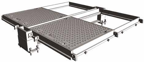
Gatic Multispan Recessed covers and frames Cover type DL recessed Multiple access covers recessed for concrete infill with removable beams. .... in no. .... (length) x .... (span) mm pit clear opening multi span cover and frame. Gatic Type DLF Ductile Iron
Recessed Cover in .... parts complete with .... in no. .... x .... mm galvanised removable support beam spanning the .... (length) mm way.
Suitable for Loading Group B125 – Medium/Light Duty 3 Tonnes Wheel Load (pneumatic tyre).
Gatic Multispan Solid Top covers and frames Cover type DLS solid top Multiple solid top access covers with removable beams. .... in no. .... (length) x .... (span) mm pit clear opening multi span cover and frame. Gatic Type DLS Ductile Iron
Cover types
Solid Top Cover in .... parts complete with .... in no. .... x .... mm galvanised removable support beam spanning the .... (length) mm way.
Suitable for Loading Group B125 – Medium/Light Duty 3 Tonnes Wheel Load (pneumatic tyre). Standard pit clear opening sizes are shown on Page 91. Beam sizes and other dimensions are shown on Pages 92 - 93.
82 www.alumascwms.co.uk +44 (0) 1787 475 151 Introduction Specification F900 E600 D400 C250 B125 Additional Covers/Gratings
Multispan covers & frames
Product Selection
Refer to the table to identify which cover and beam configuration you require against pit clear opening length (L) and pit clear opening span (S). All dimensions are in millimetres.
Cover types 1380 1530 1680 1830 1980 2160 2310 2460 2610 2760 2910 3060 3240 3090 2940 3390 3540 3690 3840 3990 4140 690 840 840 990 990 690 690 840 840 840 990 990 840 840 840 990 990 990 990 690 690 840 840 990 780 930 780 930 1080 930 1080 780 930 930 930 930 1080 1080 690 690 840 840 840 990 990 780 930 930 930 930 1080 1080 840 840 780 780 690 690 780 780 690 690 840 840 990 840 990 1300 1450 1600 1750 1900 2000 2150 2300 2450 2600 3000 2850 2700 3150 3300 3450 3600 3750 3900 Pit clear opening length (L) mm Beam centres mm Pit clear opening span (S) mm 4 parts 3 beams 3 parts 2 beams 2 parts 1 beam 2 parts 3 parts 4 parts AB CD E 2750 2900 6 part (2x3) recessed multispan cover with 2 removable support beams 9 part (3x3) recessed multispan cover with 2 removable support beams 12 part (4x3) recessed multispan cover with 2 removable support beams 8 part (2x4) recessed multispan cover with 3 removable support beams 12 part (3x4) recessed multispan cover with 3 removable support beams 16 part (4x4) recessed multispan cover with 3 removable support beams L A S B L A S B L A S B L A S B C L A S B C L A C S B L A S B C D L A S B C D L A C D S B 4020 3870 3720 4170 4320 4470 4620 4770 4920 5070 5220 690 840 840 840 990 990 990 930 930 930 930 930 930 1080 930 780 930 1080 930 1080 930 930 840 780 780 780 690 780 930 780 690 780 780 780 930 930 930 930 930 990 1080 1080 1080 1080 690 840 690 690 840 840 840 990 990 990 990 5 parts 4 beams 10 part (2x5) recessed multispan cover with 4 removable support beams 15 part (3x5) recessed multispan cover with 4 removable support beams 20 part (4x5) recessed multispan cover with 4 removable support beams L A S B C D L A S B C D L A C D E E E S B
part (2x2) recessed multispan cover with 1 removable support beam
part (3x2) recessed multispan cover with 1 removable support beam
part (4x2) recessed multispan cover with 1 removable support beam part with 2 removable support beams
4
6
8
part (2x2) multispan cover with 1 removable support beam
4
part
multispan cover with 2 removable support beam
6
(2x3)
part
3
8
(2x4)
multispan cover with
removable support beam
4
10 part (2x5) multispan cover with
removable support beam
6 part (3x2) multispan cover with 1 removable support beam
9 part (3x3) multispan cover with 2 removable support beam
cover with 3 removable support
12 part (3x4) multispan
beam
4
15
part (3x5) multispan cover with
removable support beam
8 part (4x2) multispan cover with 1 removable support beam
12 part (4x3) multispan cover with 2 removable support beam
16 part (4x4) multispan cover with 3 removable support beam
20 part (4x5) multispan cover with 4 removable support beam
83 www.alumascwms.co.uk +44 (0) 1787 475 151 Introduction Specification F900 E600 D400 C250 B125 Additional Covers/Gratings
Multispan covers & frames
Footways, pedestrian areas, car parks, driveways and internal floors

• Covers recessed for concrete infill or solid top
• Cover types: DLF (recessed) DLS (solid top)
The details below show plan and sections of a typical recessed/solid top unit. For selection and specification guidance, refer to page 90.

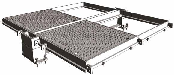
DLF recessed
Type
110 X 150 100 10 230 L W 100 v Pit clear opening length Recessed cover type DLF Direction of sliding out covers Section A - A 230 A C B B D D A B X S Pit clear opening span 100 150 75 10 57 Section B - B A C A B 43 0 Suggested rebate for end frame Suggested rebate for beam wallbox Suggested rebate for side frame Solid top cover type DLS Recessed cover type DLF Solid top cover type DLS Removable support beam (supplied by Gatic) 84 www.alumascwms.co.uk +44 (0) 1787 475 151 Introduction Specification F900 E600 D400 C250 B125 Additional Covers/Gratings
Multispan covers & frames

The required beam size for Multispan covers is dependent on the pit clear opening length and the loading group.
The table shows maximum beam length against beam size. The removable support beams are supplied by Gatic.
The table also indicates dimensions of the beam wallbox and rebate to suit different beam sizes. See also the accompanying section details.


Beam Size
Support beam size chart Type DLS solid top Type DLF recessed Note: Removable support beams are supplied by Gatic Removable support beam size Max pit clear opening length (L) Beam wallbox dimensions V W X Y 152 x 152 x 37 kg/m U.C 2750 237 259 300 230 203 x 203 x 52 kg/m U.C. 3900 281 303 345 230
pedestrian
driveways
internal floors 110 X 150 100 10 230 L W 100 v Pit clear opening length Recessed cover type DLF Direction of sliding out covers Section A - A 230 A C B B D D A B X S Pit clear opening span 100 150 75 10 57 Section B - B 100 X W 230 10 150 L Pit clear opening length Section C - C Section D - D V Direction of sliding out covers 10 110 75 S 430 A B 150 100 X Pit clear opening span Covers & rebates to be filled with 45 cube or 40 cylinder concrete during installation using 10mm coarse aggregate Full height web Solid top cover A C A B 43 0 Suggested rebate for end frame Suggested rebate for beam wallbox Suggested rebate for side frame Suggested rebate for beam wallbox Suggested rebate for side frame Suggested rebate for beam wallbox Solid top cover type DLS Recessed cover type DLF Solid top cover type DLS Removable support beam (supplied by Gatic) Removable support beam (supplied by Gatic) 85 www.alumascwms.co.uk +44 (0) 1787 475 151 Introduction Specification F900 E600 D400 C250 B125 Additional Covers/Gratings
Footways,
areas, car parks,
and
Additional access covers & drainage gratings
• Hinged security grids
• Alternative finish galvanised covers
• Hinged hydrant covers
• Solid top circular covers
• Single gratings and frames
• Trench gratings and frames
• Plug covers
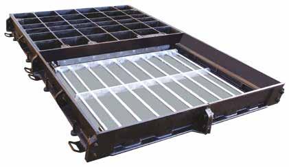
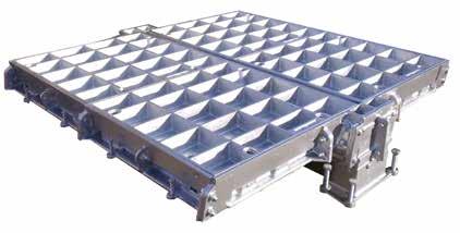
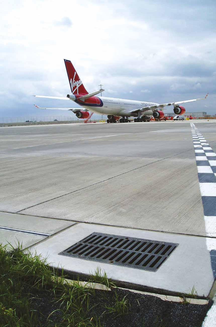

86 www.alumascwms.co.uk +44 (0) 1787 475 151 Introduction Specification F900 E600 D400 C250 B125 Additional Covers/Gratings
Loading group up to F900
Hinged security grids
Gatic covers can be supplied with mild steel galvanised security grids when required. Once the cover is removed, the security grid can be hinged to the vertical position where it will lock safely in place. Security grids can be locked in a closed position by using customer-supplied padlocks.
Hinged security grills can be fitted to all gatic units from single covers to multispan.

Alternative finish galvanised covers and gratings
Gatic covers and gratings are supplied painted with black bituminous paint as standard. This acts as temporary protection during transit. Where additional protection is required, Gatic ductile iron covers can be supplied galvanised to BS EN ISO 1461. Refer to Gatic technical department for more information.

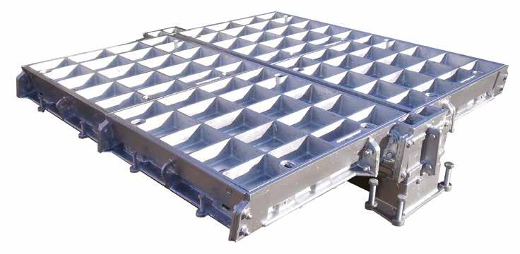
200 Pit clear opening 200 165 Clear opening - 180 Safety grid shown fully open at 110° Locked when open, lock ing unit is automaticaly engaged when safety grid is opened Safety grid hinged bracket Locked when open, lock ing unit handle 110° Security
87 www.alumascwms.co.uk +44 (0) 1787 475 151 Introduction Specification F900 E600 D400 C250 B125 Additional Covers/Gratings
Loading group up to F900

Hinged hydrant covers
Hydrant lids can be supplied as single covers or set into a larger cover. This provides localised access without removing the larger cover.
Hydrants fitted within larger covers are 400 x 300 clear opening, centrally positioned. Can be incorporated into Multi-part Cover Systems.
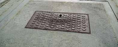
Single and double covers fitted with 400 x 300 hinged hydrant

To specify state:
1. Loading group
Hydrant covers
Solid top circular covers
Suitable for up to F900 loading.
To specify state:
1. Loading group

105 130 10 10 130 130 1030 overall (maximum) 774 overall 600 diameter pit clear opening 125 200 200 == 100
length (L) x span (S)
2. Pit clear opening size
TYPE FH TYPE GC
clear opening sizes Cover type Overall frame size length x width x depth Suggested rebate size length x width x depth 750 x 750 RSF/H 850 x 940 x 100 1100 x 1100 x 125 900 x 900 RSF/H 1120 x 1140 x 100 1300 x 1300 x 125 1600 x 750 RSF/H 1650 x 940 x 100 1800 x 1100 x 125 1900 x 900 RSF/H 2120 x 1140 x 100 2300 x 1300 x 125
clear opening sizes Cover type Overall frame size length x width x depth Suggested rebate size length x width x depth 225 x 225 FH 391 x 391 x 150 525 x 525 x 175 500 x 250 FH 666 x 416 x 150 800 x 550 x 175 C/O Cover shown in open position. (110° minimum) 78 88 150 150 250 175 150 700 100 10 Pit clear opening 300 C/O Cover shown in open position. (110° minimum) 78 88 150 150 250 175 150 700 100 10 200 Pit clear opening span 300 165
3. Cover type
Pit
Pit
2. Pit clear opening size
hydrant covers
3. Cover type Double
and double units - including a 400 x 300 hinged hydrant cover centrally positioned in each cover Pit clear opening sizes Cover type Overall frame size Suggested rebate size length x width x depth 600mm diameter GC 775 diameter 1000 diameter 750mm diameter GC 925 diameter 1150 diameter 900mm diameter GC 1075 diameter 1300 diameter Note: D400 covers available upon request.
Single
88 www.alumascwms.co.uk +44 (0) 1787 475 151 Introduction Specification F900 E600 D400 C250 B125 Additional Covers/Gratings
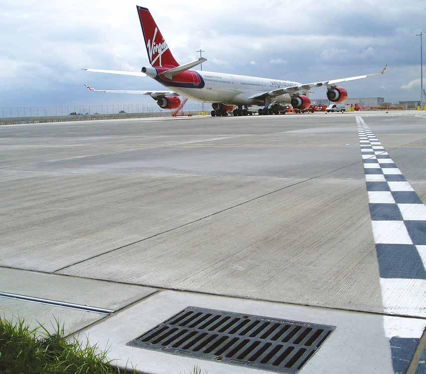
Single gratings
Single gratings with shutter plates
Single gratings and frames
Drainage gratings are supplied where surface water drainage is required.
To specify state:
1. Loading group
2. Pit clear opening size length (L) x span (S)
3. Grating type

Pit clear opening sizes Grating type Overall frame size length x width x depth Suggested rebate size length x width x depth Waterway per unit 850 x 300 DRG/140 870 x 480 x 140 1000 x 700 x 165 1256cm2 850 x 450 DRG/140 870 x 630 x 140 1000 x 850 x 165 2215cm2 600 x 600 DRG/100 620 x 780 x 100 750 x 800 x 125 1991cm2 850 x 600 DMG 870 x 780 x 140 1000 x 1000 x 165 2768cm2 Pit clear opening sizes Grating type Overall frame size length x width x depth Suggested rebate size length x width x depth Waterway pre unit 914 x 310 DRG/140/S 950 x 480 x 140 1065 x 700 x 165 1256cm2 914 x 457 DRG/140/S 950 x 630 x 140 1056 x 850 x 165 2215cm2 914 x 610 DMG/140 950 x 780 x 140 1065 x 1000 x 165 2768cm2
80 7 S 140 165 Pit clear opening span Pit clear opening span Rebates to be filled with 45 cube or 40 cylinder concrete during installation using 10mm coarse aggregate 10 100 200 165 140 S 200 200 200 Rebates to be filled with 45 cube or 40 cylinder concrete during installation using 10mm coarse aggregate 165 850 850 75 75 Pit clear opening 700 or 850 165 700 or 850 75 75 Pit clear opening 80 7 S 140 165 Pit clear opening span Pit clear opening span Rebates to be filled with 45 cube or 40 cylinder concrete during installation using 10mm coarse aggregate 10 100 200 165 140 S 200 200 200 Rebates to be filled with 45 cube or 40 cylinder concrete during installation using 10mm coarse aggregate 165 850 850 75 75 Pit clear opening 700 or 850 165 700 or 850 75 75 Pit clear opening 80 7 S 140 165 Pit clear opening span Rebates to be filled with 45 cube or 40 cylinder concrete during installation using 10mm coarse aggregate 200 200 165 850 850 75 75 Pit clear opening 80 7 S 140 165 Pit clear opening span Rebates to be filled with 45 cube or 40 cylinder concrete during installation using 10mm coarse aggregate 200 200 165 850 850 75 75 Pit clear opening 700 or 850 165 700 or 850 75 Pit clear opening Type DRG/140 950 overall shutter plates Pit clear opening Pit clear opening 914 80 77 80 165 165 140 75 75 Shutter plates Rebates to be filled with 45 cube or 40 cylinder concrete during installation using 10mm coarse aggregate 310 200 200 Frame levelling bolt plates Type DRG/140/S - DMG/S similar Type DMG S Loading group up to F900 89 www.alumascwms.co.uk +44 (0) 1787 475 151 Introduction Specification F900 E600 D400 C250 B125 Additional Covers/Gratings Tel: +44 (0)1787 475151

Trench gratings and frames
Gatic gratings and frames can be manufactured in continuous runs. A layout drawing with enquiries will enable our technical department to design an appropriate layout of gratings.
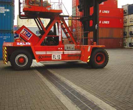
Pit clear opening sizes C250 Type D400 Type E600 Type F900 Type Waterway per metre 300 DRG/100 DRG/100 DRG/100 DRG/100 1813cm2 450 DRG/100 DRG/100 DRG/100 DRG/100 2629cm2 600 DRG/100 DRG/100 DRG/100 3445cm2 750 DRG/100 DRG/100 DRG/100 4329cm2 810 DRG/100 DRG/100 DRG/100 4466cm2 1000 DRG/100 DRG/100 DRG/100 5262cm2 Trench gratings 78 12 S 125 100 Pit clear opening span Rebates to be filled with 45 cube or 40 cylinder concrete during installation using 10mm coarse aggregate 150 150 modular length 1000 125 10 End termination plate Section through drainage trench Section through end terminal Type DRG/100 All Type DRG/100 gratings and frames available in 1000mm lengths except 1000mm c/o span for E600/F900 loadings which are 500mm lengths.
group up to F900 90 www.alumascwms.co.uk +44 (0) 1787 475 151 Introduction Specification F900 E600 D400 C250 B125 Additional Covers/Gratings
Loading
Loading group up to C250
Plug covers
Loading groups up to C250
Small insert plug covers can be fitted to a wide range of cover sizes. Maximum 300 x 300 plug clear opening. Refer to Gatic technical department for more information.

Holes and cut-outs
Holes and cut-outs can be provided in covers to allow for the positioning of valves, pipes and cables. These can be square or circular, loading suitable for C250.
Upstands can be fitted to prevent the ingress of water around pipes and valves.


91 www.alumascwms.co.uk +44 (0) 1787 475 151 Introduction Specification F900 E600 D400 C250 B125 Additional Covers/Gratings
Single cover and frames
Single cover and frames
1 Prepare the rebate in accordance with dimensions given in the relevant tables within this publication and/or accompanying drawings.
2 Remove cover from frame and place frame squarely over pit ensuring it does not overhang any edges.
3 Screw down on the frame levelling bolts until the desired height is achieved.
4 Place formwork around inside of pit so that the timber is approximately 10mm above the bottom of the frame. This will prevent spalling of the frame.
Do not pour concrete at this stage.
5 Clean off cover and frame sealing faces and replace cover into frame.
6 Adjust the frame level so that the cover is not rocking. Tap down the corners of the covers with a balk of timber to make sure it is seated fully.
7 If covers are of the recessed design you will need to cover the 4 holes in the cover base with a small metal or slate plate.
8 Insert the plastic keyhole plugs and mask off with tape.
9 Pour concrete in the covers, if of the recessed type, and around the frames making sure that you thoroughly tamp and vibrate as you go.
10 Allow concrete to cure overnight.
11 Remove cover and strike shuttering.
12 Clean faces of covers and frame and apply a thin film of graphite grease to the seating faces.
13 Replace cover into the frame and tap down with a balk of timber.
14 Allow the concrete to fully mature before any load is applied.
4 holes in base of cover Leveling bolts Plastic keyhole plug Concrete Shuttering Concrete
92 www.alumascwms.co.uk +44 (0) 1787 475 151 Introduction Specification F900 E600 D400 C250 B125 Additional Covers/Gratings
Ducts and trenches
1. Prepare the rebate in accordance with dimensions given in the relevant tables within this publication and/or accompanying drawings. They are also numbered in sequence.
2. Covers and frames are supplied pre-matched and banded together. Do not remove banding at this stage.
3. Commence at one end of the pit, or if there is a junction then commence at this point. Identify the relevant covers and frames at this location.
4. Place first assembled section squarely over the pit ensuring it is in alignment with the centre of the pit.
5. Identify the next assembly. This is done by locating the next number in the sequence, offering up to the first portion and loosely bolting the frame together. Numbers are painted on the ends of the covers to correspond with the drawings supplied.
6. Adjust the height of the frames to the required level by using the levelling bolts in the frame.
7. Repeat along the length of the trench making sure the covers are following a straight line.
8. Visually check that your covers are in the correct frames and order by looking for the random grinding nicks around each cover perimeter on the top surface.
9. In sections, remove covers from frames and place formwork around inside of pit so that the timber is approximately 10mm above the bottom of the frame. This will prevent spalling of the frame.
Do not pour concrete at this stage.
10. Clean off covers and frame seating faces and replace cover into the frame.
11. Check that the grinding nicks still correspond.
12. Adjust the frame level so that the cover is not rocking. Tap down the corners of the covers with a balk of timber to make sure it is seated fully.
13. Using the assembly clamps provided, clamp the covers to the frames and across cover to cover joints. This will ensure that the covers are seated properly.
14. Moving round the frame, with the covers in place, tighten the frame bolts making sure you do not damage the lead packers or over-tighten the bolt.
15. If covers are of the recessed design, you will need to cover the small holes in the cover base with a small metal or slate plate.
16. Insert the plastic keyhole plugs and mask off with tape.
17. Pour concrete around the frames to a depth of about 25mm up the back of the frame and tamp or vibrate as you go.
18. Allow to cure overnight then remove the assembly clamps.
19. Pour concrete into the recessed covers, and around the frames, making sure that you thoroughly tamp and vibrate as you go.
20. Allow concrete to cure overnight.
21. Remove cover and strike shuttering.
22. Clean faces of covers and frame and apply a thin film of graphite grease to the seating faces.
23. Replace cover into the frame and tap down with a balk of timber. Once again make sure that the grinding nicks match up.
24. Allow the concrete to fully mature before any load is applied.
holes in base of cover Number on inside of frame and underside of cover Leveling bolts
4
clamp Shuttering
Assembly
Assembly clamp Shuttering
plug Concrete
93 www.alumascwms.co.uk +44 (0) 1787 475 151 Introduction Specification F900 E600 D400 C250 B125 Additional Covers/Gratings
Plastic keyhole
Shuttering Concrete
Multispan covers and frames
Form the frame and wallbox rebates around the pit strictly in accordance with Gatic’s drawing. It is important to follow the stated dimensions otherwise the multispan cover will not fit.
The frame is delivered in sections together with beam assemblies and covers. Ensure that the end frames match with the side frame components.
The end frames can be identified as those sections with the beam end wallbox forming part of their construction. Frame sections and beam assemblies are numbered to help locate the cover positions.
Identification numbers are shown on the cover layout drawing supplied. Numbers can be found painted on the ends of covers, beams and outside faces of frames. Number tags are also fixed to the underside of the cover and also to the frame and beams.
The lowest numbers in each row of covers indicate that this is the front end of the unit.
1. Position the front end frames in the wallbox pockets and loosely join the sections together in the middle and at the corners.
2. Locate the side frame assemblies. These are handed so that they only fit on the correct side of the cover, and offer up to the back end frames. Remember that there are a number of small frame pieces that make up a straight frame.
3. Check that lead spacers at the frame joints have not been damaged otherwise the frame will no longer mate with the cover. Again loosely bolt the frames together.
4. Using the large ‘Tommy Bar’ gradually screw down on the levelling bolts on the bottom of the wallboxes until the top of the frame is approximately level with the finished floor level.
5. Now using the small ‘Tommy Bar’ adjust the side frames up to approximate finished level.
6. Locate the correct beam assembly, look for the numbers painted on the beam and corresponding tags on the frame, and lower into the wallboxes.
7. Tap down on the filler block, using a rubber mallet,and then, using the small assembly clamp, clip the end of the beam into the wallbox. (If the filler block is not flush then the beam is not seated correctly in the wallbox and you will need to adjust it accordingly).
8. Dimensionally check the frame is roughly square andnot overhanging the edge of the pit.
Do not pour concrete at this stage.
9. Clear any debris from the seating faces of the covers and frames and, starting with the middle row, lay the three covers down between the two beams.
10. With the three covers in position, adjust the wallbox levelling bolts to attain the required height, and also to make sure that the covers are seated correctly and not rocking.
11. Position one of the outer rows and this time adjust the levelling bolts until the covers do not rock.
12. Repeat for the other end row. The covers are now sound enough to walk on to check that they are not rocking.
13. Walk across the covers and tap the corners with a balk of timber to ensure that they are firmly down.
14. Using the assembly clamps provided, you can now pull the covers tightly together and into the frames to ensure the unit is correctly seated.
15. Visually check the top edges of the covers and frames making sure that random grinding marks align with each other.
16. Now go round the frame and tighten all loose connected frame joints, but do not over-tighten. They only need to be nipped up.
17. Remove the covers and carefully stack at the side of the pit.
18. Place timber shuttering around the inside perimeter of the pit and brace as appropriate. The shuttering should sit approximately 10mm higher than the bottom of the frame.
19. Replace the covers, taking care that they are in the correct location, check that there is still no rock, and then clamp the covers in place as before.
20. Place small thin pieces of cut steel over the holes in the cover base plates, insert keyhole plugs and place masking tape over them. The cover is now ready to receive concrete.
Beam assembly Slide frames End frames Small assembly clamp Large assembly clamp Tommy bars Covers
94 www.alumascwms.co.uk +44 (0) 1787 475 151 Introduction Specification F900 E600 D400 C250 B125 Additional Covers/Gratings
Multispan covers and frames
21. Leave the assembly clamps in place and part fill the rebate around the frame, going approximately 25mm up the back of the frame and thoroughly tamping or vibrating to ensure that it flows under the frame. Leave for 24 hours to set.
22. Remove clamps and proceed to infill around the rest of the frame and inside the covers,thoroughly tamping as you go.
23. Float off the surface to the desired texture.
24. Remove covers from the frames and strike the shuttering, checking that the concrete has fully flowed under the frame.
25. Clean off covers and beams.
26. Lightly grease the blocks on the end of the beams and place in position.
27. Lightly grease faces and covers and replace in frames, checking that the grinding marks align.
28. Allow the concrete to fully mature before any load is applied.


Why not watch the access cover tutorial presentation on YouTube?
Explains the installation process and how to go about a multi-span installation including the Gatic 2000 Access Cover.
If you need more information speak to our technical team on +44 (0)1787 475151
 Gatic tutorial
CLICK TO PLAY 95 www.alumascwms.co.uk +44 (0) 1787 475 151 Introduction Specification F900 E600 D400 C250 B125 Additional Covers/Gratings
Gatic Tutorial
Lifting keys

Manual jack screw key operation.
Method of removing Gatic covers using manual lifting keys.
1. Clear all obstructions from key holes.
2. Slacken off jack screw before placing key in position.
3. Insert tee bolt in the key hole, turn clockwise through 90º and tighten lock nut.
4. Jack screw can now be tightened to act on the frame and break seal.
5. Lift front and slide out cover.
6. Slacken off jack screw before replacing cover.
Long handled lifting keys (pair)
Not for use with mechanical or crane lifting.
Mechanical lifting keys
Mechanical lifting keys are designed and tested for use with crane and other mechanical devices.
Consult technical department for full details.
Indicator stop plate Main body Tee bolt Jacking bolt Indicator stop plate Main body Tee bolt Jacking bolt Long handle Tee bolt and indicator plate to move freely in main body Indicator plate Main body Long handle Tee bolt Cover Note correct alignment of indicator plate with tee bolt Jacking bolt Long handle Tee bolt and indicator plate to move freely in main body Indicator plate Main body Long handle Tee bolt Cover Note correct alignment of indicator plate with tee bolt Jacking bolt
96 www.alumascwms.co.uk +44 (0) 1787 475 151 Introduction Specification F900 E600 D400 C250 B125 Additional Covers/Gratings Website: www.gatic.com Email: info@gatic.com

Gatic Third Avenue
Halstead
Essex CO9 2SX
+44 (0) 1787 475 151
gatictech@alumascwms.co.uk
ARCHITECTURAL ALUMINIUM BUILDING DRAINAGE WA DE DRAINAGE & ACCESS COVERS All reasonable care has been taken in the preparation of this brochure, all information, recommendation and guidance notes on the use of The Products are made without guarantee since the conditions of use are beyond the control of Alumasc Building Products Limited (The company). The customer is responsible for ensuring that each product is fit for its intended purpose and that conditions are suitable. The information contained in this brochure and advice arising there from is free of charge and accordingly on the terms that no liability nor liability for negligence will attached to The Company or its servants in relation to any such service arising out of or in connection with this brochure. The Company pursues a policy of constant product development and information contained in this publication is therefore subject to change without notice.
DRAINAGE & ACCESS COVERS


 Single covers and frames
Duct covers and frames
Pave
Continuous trench covers and frames
Multispan covers and frames
Product Ranges


 Single covers and frames
Duct covers and frames
Continuous trench covers & frames
Multispan covers and frames


 Gatic tutorial

