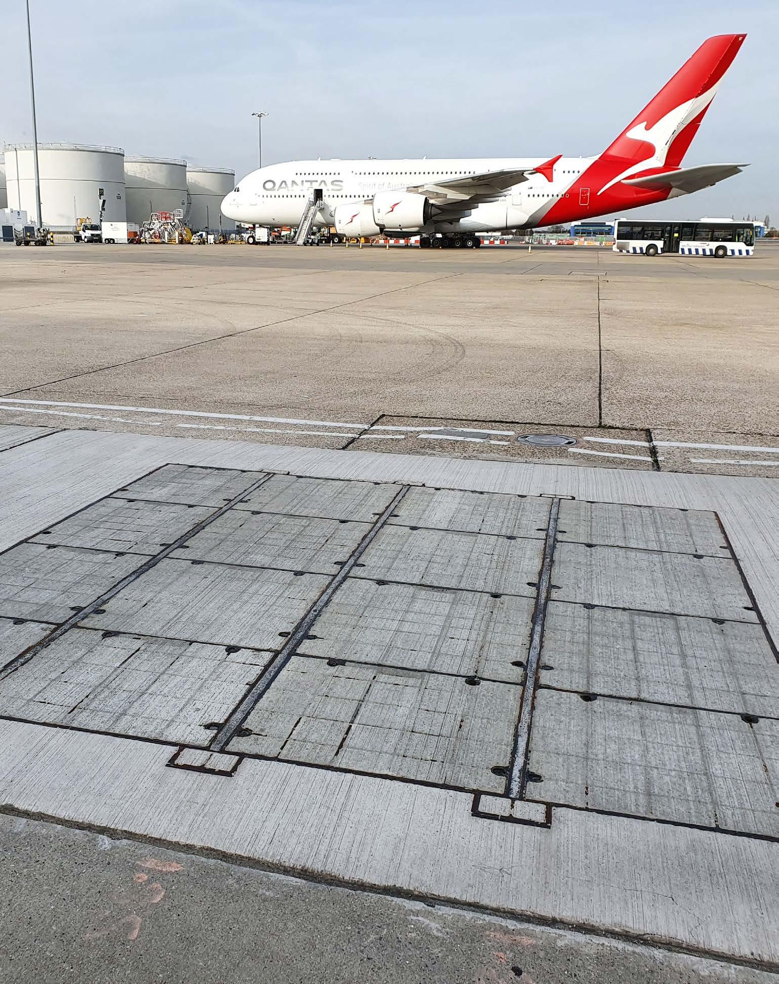
At Gatic, we know that our reputation is only as good as the performance of our products. That is why we do our best to ensure that the product you buy is the right one for the job and you have all the technical resources and support you need for successful installation.
Technical Support: Get the right advice at the right time
Whether your project is big or small, our design engineers are available to discuss the technical aspects of any project involving Gatic covers. A bit of expert insight from our engineers can help get your project back on track.
You can contact our team via our website, phone or email.
Learn more about Gatic products
Tel: +44 (0)1787 475 151
coverstech@alumascwms.co.uk
www.gatic.com
Learn how Gatic covers are constructed and fitted on site on our website. Our website now contains even more technical information and guidance than before. We have increased our online resources and improved the website design so you can now find all the technical information you need for your projects easily and quickly.
Within each product range, you can explore features and benefits, technical details, graphics, diagrams, and case studies.
The Alumasc Water Management Solutions Family
Alumasc (AWMS) is a UK-based supplier of premium building products. The majority of the group’s business is in the area of sustainable building products which enable customers to manage energy and water use in the built environment.
They include: Skyline Architectural Aluminium; Alumasc Rainwater Gutters & Downpipes; Harmer Building Drainage; Wade Building Drainage and Gatic Drainage & Engineered Access Covers.
Lifting Keys
Long handled lifting keys
(not for use with mechanical or crane lifting)
Manual jack screw key operation.
Method of removing Gatic covers using manual lifting keys.
1. Clear all obstructions from key holes.
2. Slacken off jack screw before placing key in position.
3. Insert tee bolt in the key hole, turn clockwise through 90º and tighten lock nut.
4. Jack screw can now be tightened to act on the frame and break seal.
5. Lift front and slide out cover.
6. Slacken off jack screw before replacing cover.
Mechanical lifting keys
Mechanical lifting keys are designed and tested for use with cranes and other mechanical devices.
Consult Gatic’s technical department for full details.
If in doubt, always consult your Gatic technical representative. Call: +44 (0) 1787 475 151
Email: coverstech@alumascwms.co.uk
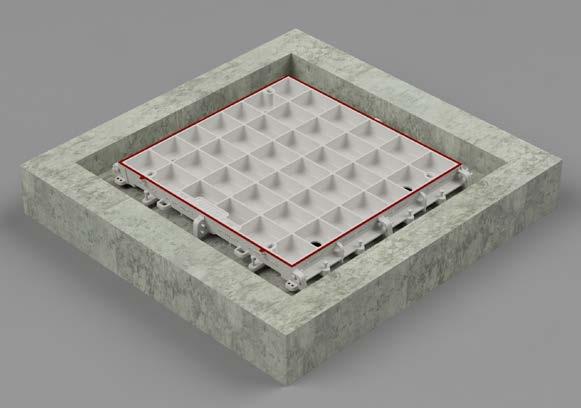
Single Covers and Frames
Installation Instructions
1. Prepare the rebate in accordance with dimensions in the given drawings.
2. Remove cover from frame and place frame squarely over pit ensuring it does not overhang any edges.
3. Adjust levelling bolts until the desired height is achieved.
4. Place formwork around inside of pit so that the timber is approximately 10mm above the bottom of the frame. This will prevent spalling of the frame.
Do not pour concrete at this stage.
5. Clean off cover and frame sealing faces and replace cover into frame.
6. Adjust the frame level so that the cover is not rocking. Tap down the corners of the covers with a balk of timber to make sure it is seated fully.
7. If covers are of the recessed design you will need to cover the 4 holes in the cover base with a small metal or slate plate.
8. Insert the plastic keyhole plugs and mask off with tape.
9. Pour concrete to the specification supplied on the installation drawing. Follow the concrete supplier’s technical advice and guidance. If the cover is of recessed type, it is recommended that the periphery frame infill is complete and cured for 24hrs before the cover infill is conducted. See concrete recommendations on page 8.
10. Allow concrete to cure overnight
11. Remove cover and strike shuttering.
12. Clean faces of covers and frame and apply a thin film of graphite grease to the seating faces.
13. Replace cover into the frame and tap down with a balk of timber.
14. Before the cover assembly is put into service, Gatic recommends that the site’s structural engineer inspect and sign off the construction.
If in doubt, always consult your Gatic technical representative.
Call: +44 (0) 1787 475 151
Email: coverstech@alumascwms.co.uk
Four holes in base of cover
Leveling bolts
Plastic keyhole plug Concrete
Concrete Shuttering
Ducts and Trenches
Installation Instructions
1. Prepare the rebate in accordance with the dimensions in the drawings given.
2. Position and Assemble the Trench / Duct frame periphery bars in accordance with the technical and Drawing information supplied.
3. Once assembled, adjust the levelling bolts to the desired position.
4. Check that the covers and frame seating face are clean, and place the covers according to the drawings supplied. Check the covers are fully seated and re-adjust the frame if required.
5. Remove covers and build shuttering between the chamber and frame assembly.
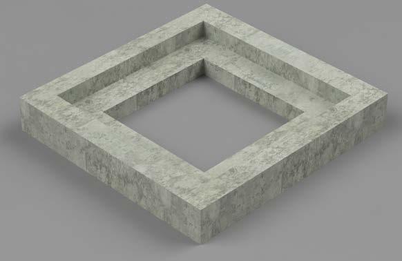
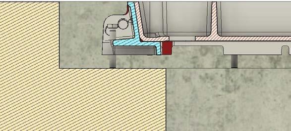
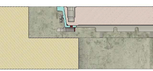
6. If covers are of recessed design, ensure base holes are covered as per Figure 1.
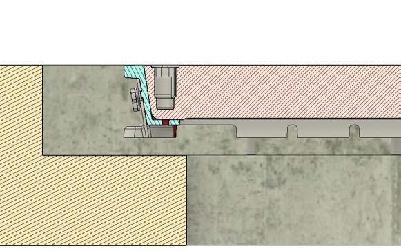
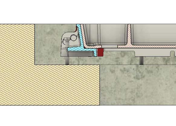
7. Replace covers into Periphery Frame. Ensure Plastic key hole plug are in place see Figure 2.
8. Pour concrete into the rebate and to the specification supplied on the installation drawing. Follow the concrete supplier’s technical advice and guidance*.
9. Once the rebate concrete is cured, pour concrete into the recessed covers to the specifications supplied. Follow the concrete supplier’s technical advice and guidance*.
10. Before the cover assembly is put into service, Gatic recommends that the site’s structural engineer inspect and sign off the construction.
If in doubt, always consult your Gatic technical representative. Call: +44 (0) 1787 475 151 Email: coverstech@alumascwms.co.uk
Four holes in base of cover
Leveling bolts
Plastic keyhole plug Concrete
Concrete
Shuttering
FIG.1
FIG. 2
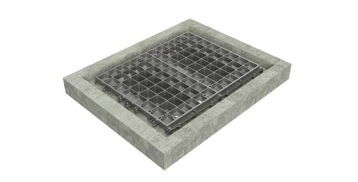
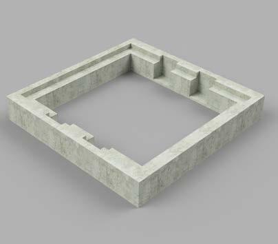
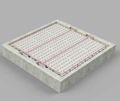
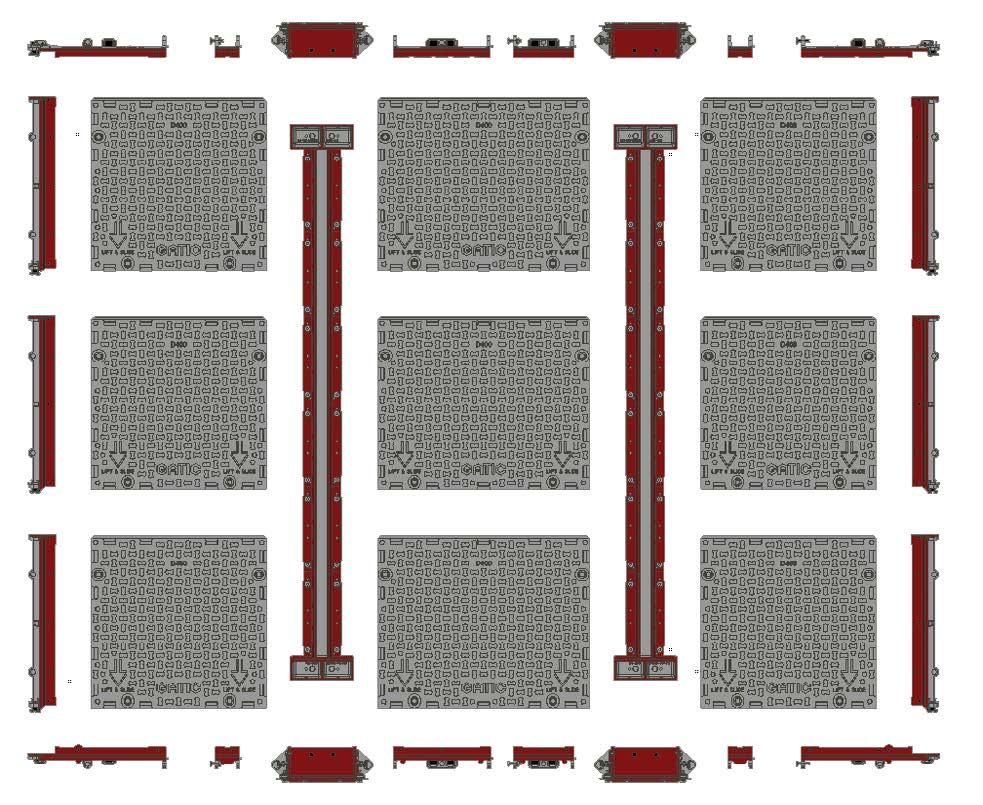
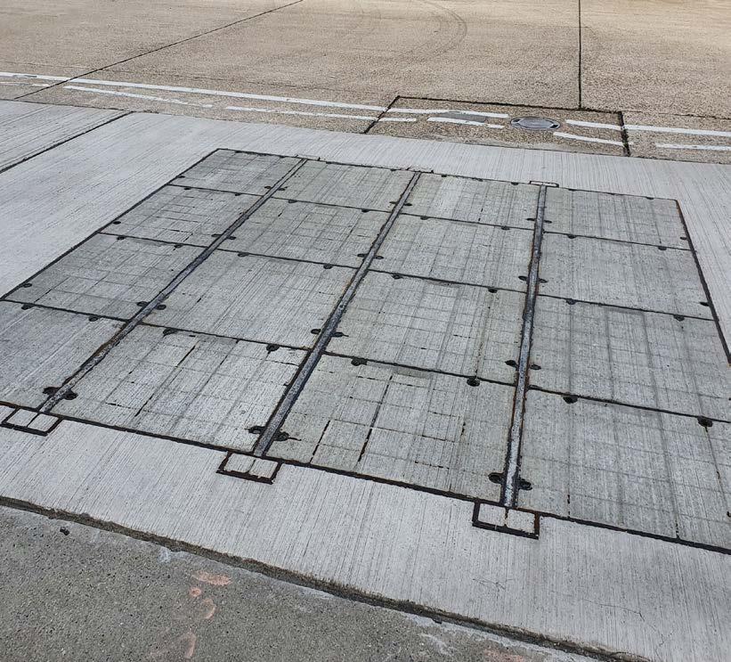
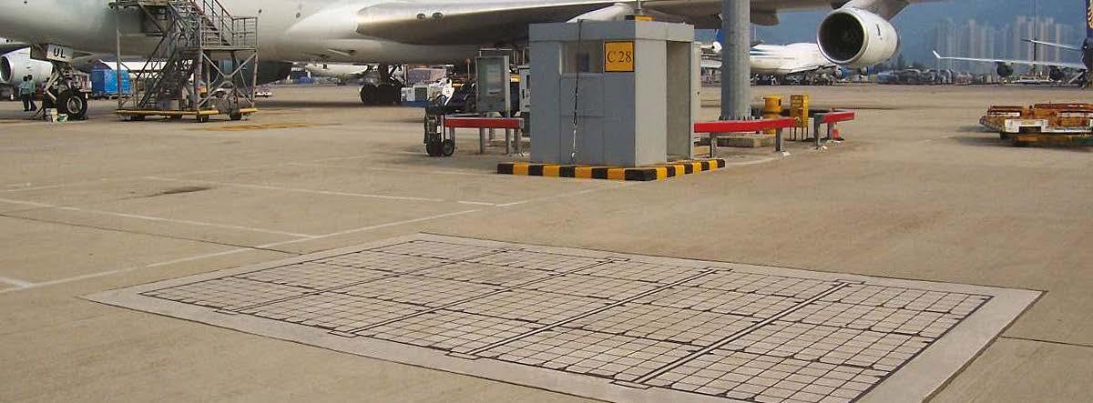
Multispans
Installation Instructions
1. Prepare the rebate in accordance with the dimensions in the drawings given.
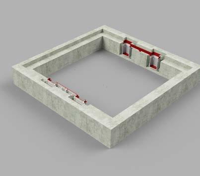
2. Position the end frame and wall box assemblies according to the technical/ drawing information supplied.
3. Place the Beam assemblies into the wallbox. Correctly level the Beam via the jacking bolts within the wallbox assemblies.
4. Assemble the remaining periphery and side bars to complete the frame and assembly.
5. Once assembled, adjust the levelling bolts to the desired position.
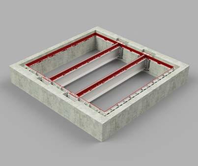
6. Check that the covers and frame seating face are clean, and place the covers according to the drawings supplied.
Check the covers are fully seated and re-adjust the frame if required.
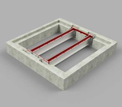
7. Remove covers and place form.
8. If covers are of recessed design, ensure base holes are covered as per Figure 1.
9. Replace covers into Periphery Frame. Ensure Plastic key hole plug are in place see Figure 2.
10. Pour concrete into the rebate and to the specification supplied on the installation drawing. Follow the concrete supplier’s technical advice and guidance*.
11. Pour concrete to the specification supplied on the installation drawing. Follow the concrete supplier’s technical advice and guidance. If the cover is of recessed type, it is
recommended that the periphery frame infill is complete and cured for 24hrs before the cover infill is conducted. See the concrete recommendations on page 8.
12. Before the cover assembly is put into service, Gatic recommends that the site’s structural engineer inspect and sign off the construction.
If in doubt, always consult your Gatic technical representative.
Call: +44 (0) 1787 475 151
Email: coverstech@alumascwms.co.uk
Leveling bolts
Plastic keyhole plug Concrete
Concrete Shuttering
FIG.1
FIG. 2
Four holes in base of cover
Multispans
Diagram of all individual parts
Concrete Recommendations
Concrete recommendations for installation and infill
These recommendations are given as guidelines only - follow the concrete supplier’s technical advice and guidance. We will not accept any liability from their application. The choice of materials must be appropriate to the specific conditions of location, environment and use case.
The expected quality shall be the same as required for construction work concrete with high mechanical performances to a minimum specification of C32/40.
Before the cover assembly is put into service, Gatic recommends that the site’s structural engineer inspect and sign off the construction to ensure these minimum requirements are met.
The covers are secured in place using the maintenance bolt down method defined in the maintenance section.
If in doubt, always consult your Gatic technical representative. Call: +44 (0) 1787 475 151
Email: coverstech@alumascwms.co.uk
Maintenance Procedures
Important
1. Maintenance procedures must be carried out according to the relevant environmental conditions.
2. Operators should wear appropriate PPE.
If in doubt, always consult your Gatic technical representative.
3. Cleaning Equipment – Non-caustic cleaning agents only
4. Brush for Grease application
Cover Maintenance
1. Remove plastic caps.
2. Clean keyholes.
3. Unscrew and remove bolts and washers.
4. Lift out the cover using the Lifting Keys.
5. Scrape and wipe all grease and contaminants from the vertical and horizontal machined surfaces of the cover and frame.
6. Remove debris and thoroughly clean bolt holes and keyholes.
7. Clean the applicable threads.
8. Make sure all surfaces are clean before applying grease to the cover, and apply grease to the frame-machined surfaces.
9. Replace the covers into the frame assembly in their correct position according to size. The cover is interchangeable.
10. Replace locking bolts (if applicable).
11. Tighten the Bolts, walk on or tap with a mallet to settle covers in place, and re-tighten bolts – use of an impact wrench is not recommended.
12. Clean off any excess grease.
13. Replace the plastic keyhole caps.
Maintenance Procedures
Beam Maintenance
1. General Considerations
• The galvanized steel beams must be inspected annually for any damage to the galvanization. Any detected damage should be repaired as per the appropriate galvanization repair process.
• Ensure that the machined faces of the filler blocks on the ends of the beam are cleaned and regreased each time the beams are removed.
2. Lifting Procedure
• The exact lifting process is to be determined by the contractor or client on-site, depending on the available lifting equipment.
• Mechanical equipment such as a Hiab, used in conjunction with either lifting chains or lifting strops, is recommended for safe removal and replacement of the beams.
• Ensure that all lifting equipment is certified and has undergone the necessary pre-use inspections.
3. Health and Safety Considerations
• The contractor or client is responsible for adhering to all relevant health and safety regulations during the lifting process.
• Conduct a risk assessment before lifting operations begin to identify potential hazards and implement necessary control measures.
• Operators should wear appropriate PPE, including gloves, safety boots, high-visibility clothing, and hard hats.
• Only trained and competent personnel should be involved in the lifting operation.
• The work area should be cordoned off to prevent unauthorized access and ensure a safe working environment.
4. Beam Removal and Replacement
• Position the lifting equipment securely and ensure it has the required load capacity.
• Attach lifting chains or lifting strops to the beam securely before commencing the lift.
• Lift the beam steadily to avoid sudden movements that may cause damage or instability.
• After removal, clean the machined faces of the filler blocks on the beam ends and apply grease before reinstalling. Ensure sole plates (bottom of wallbox frame) is clear of any debris.
• Lower the beam into position carefully, ensuring correct alignment before securing it in place.
5. Post-Lifting Inspection and Maintenance
• After installation, inspect the beam and surrounding components for any signs of damage or misalignment.
• Verify that the beam is securely in place and that all fastenings are correctly tightened.
• Document the lifting operation, including any issues encountered and corrective actions taken.
If in doubt, always consult your Gatic technical representative. Call: +44 (0) 1787 475 151