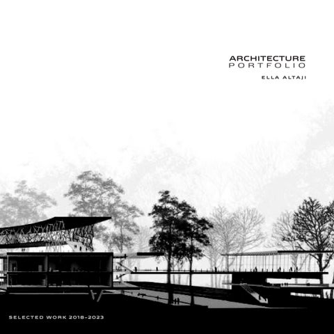
ELLA ALTAJI
I
ARCHITECTURE PORTFOLIO
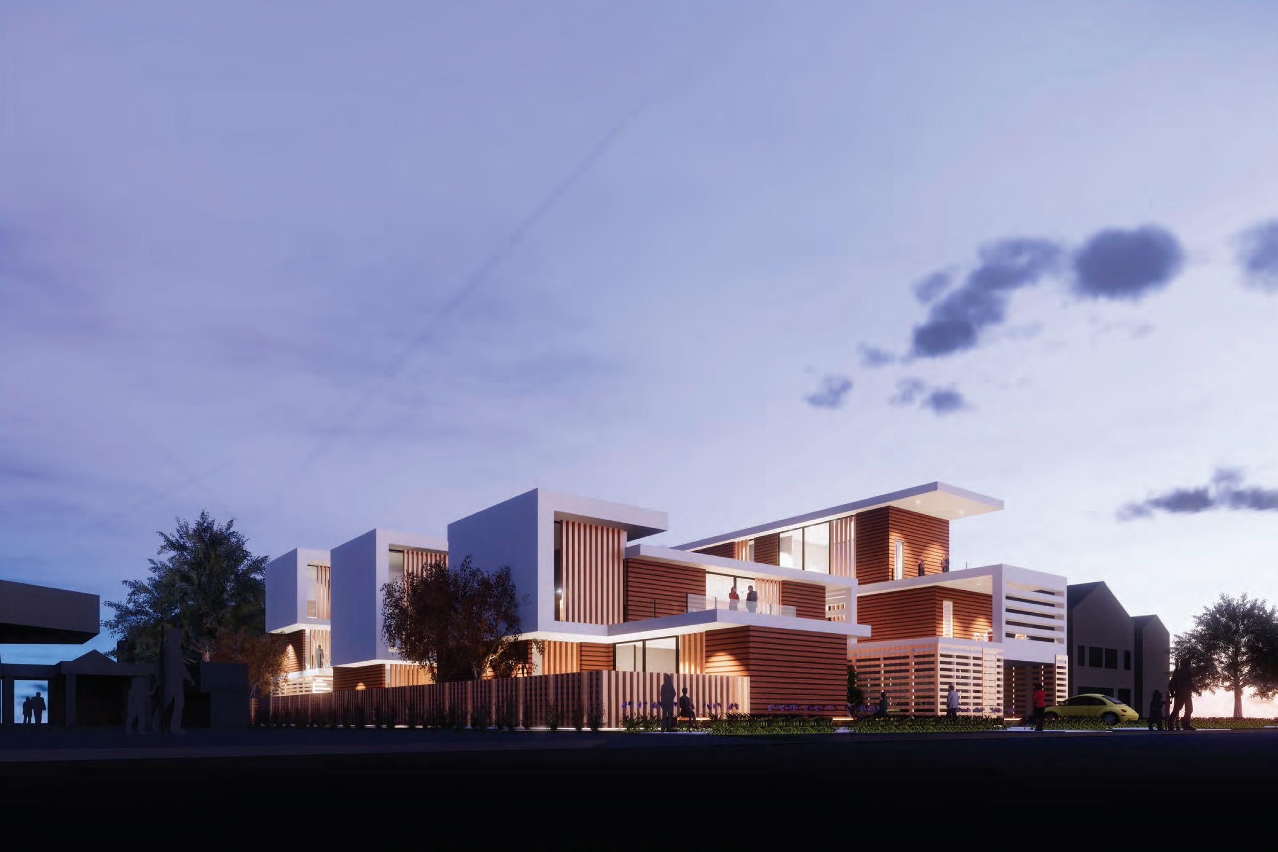

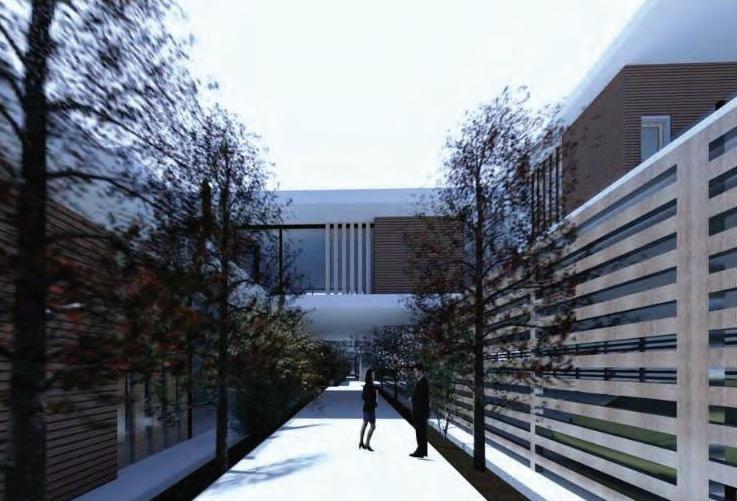
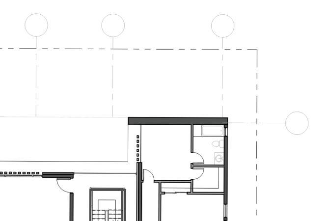
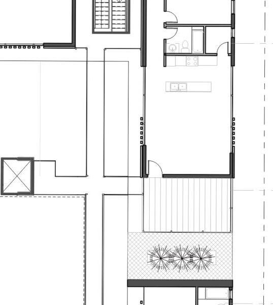
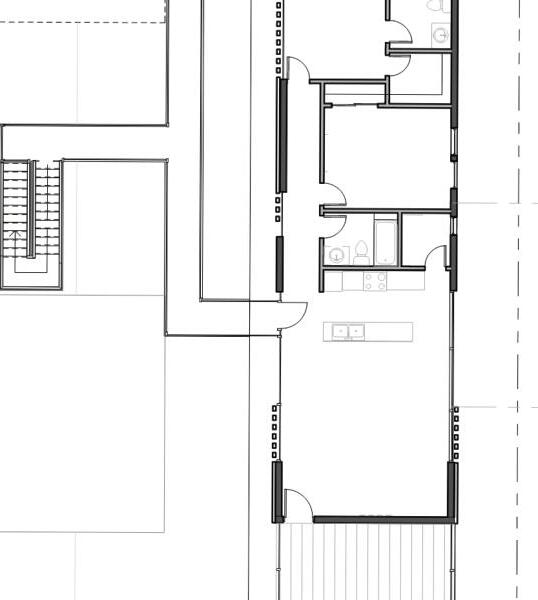
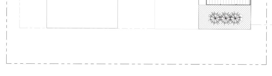
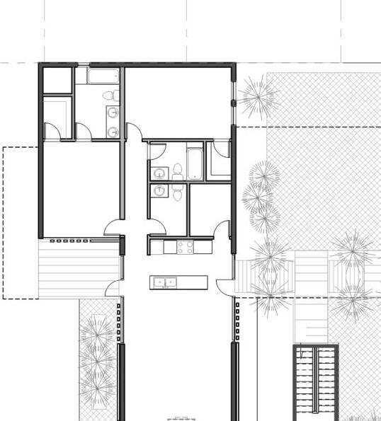
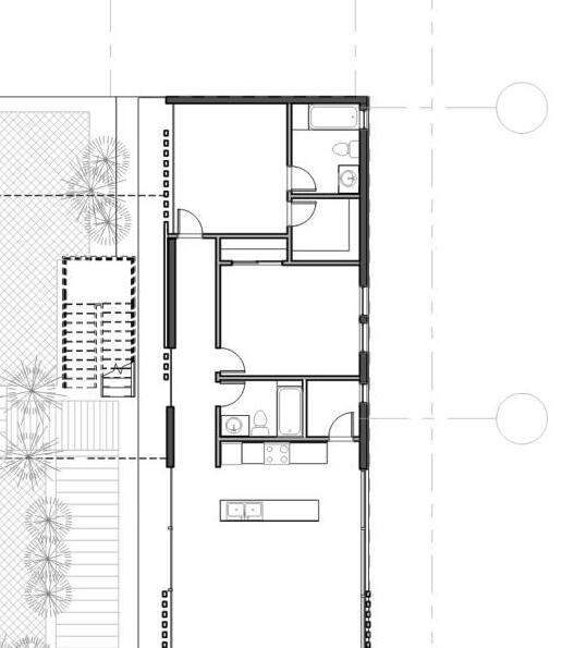
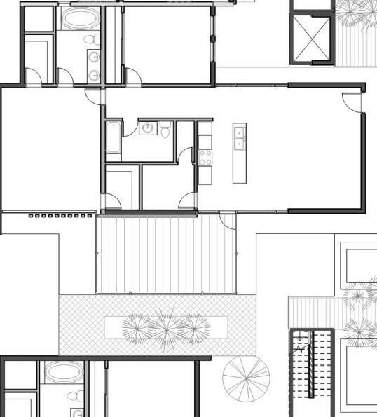
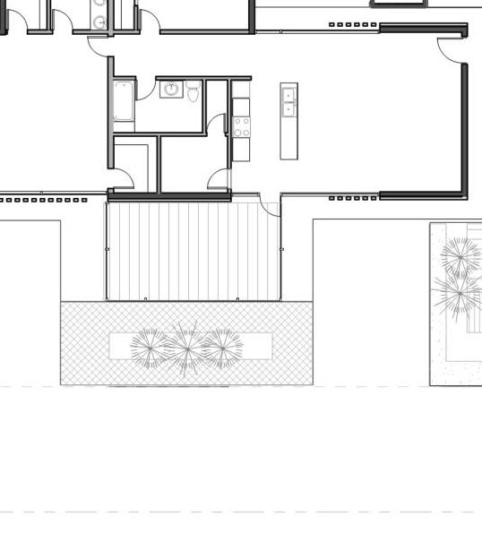
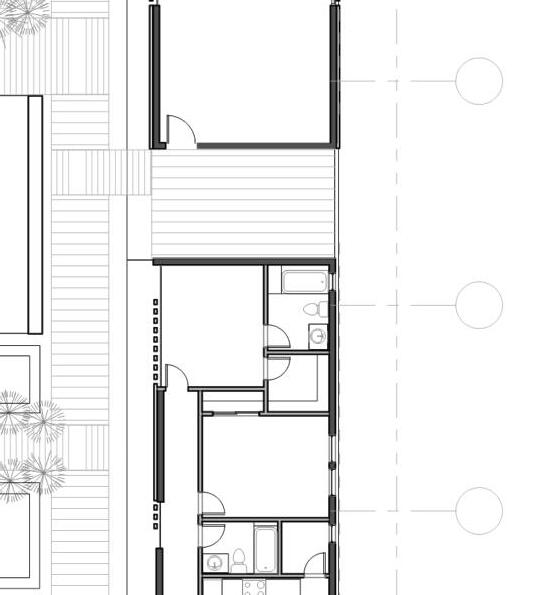
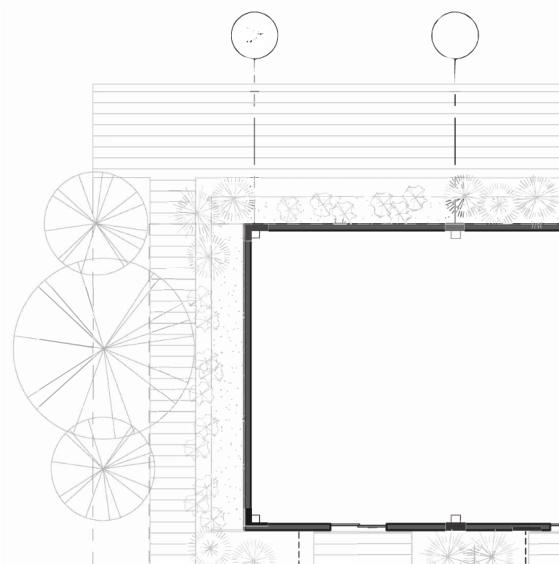
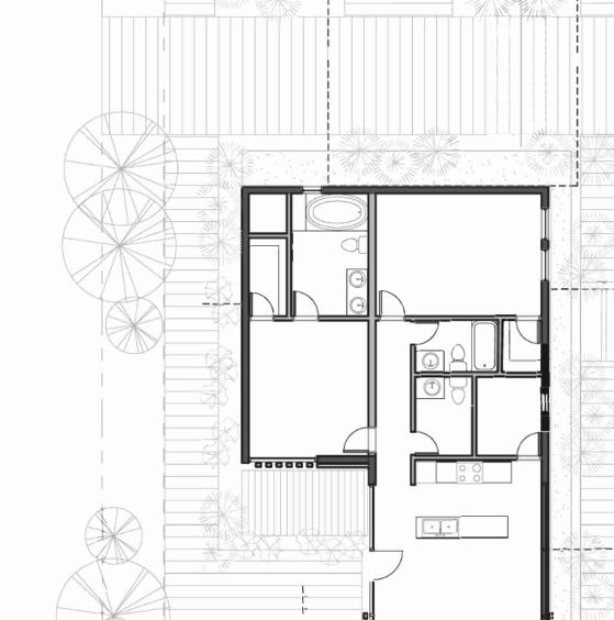
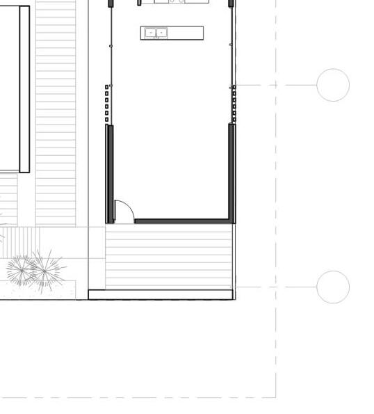
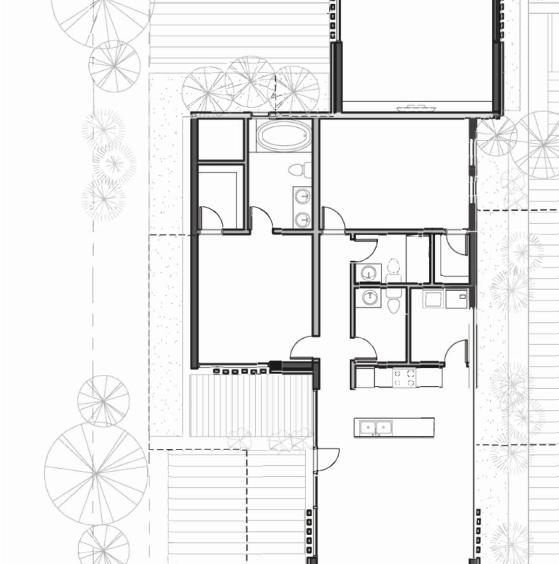
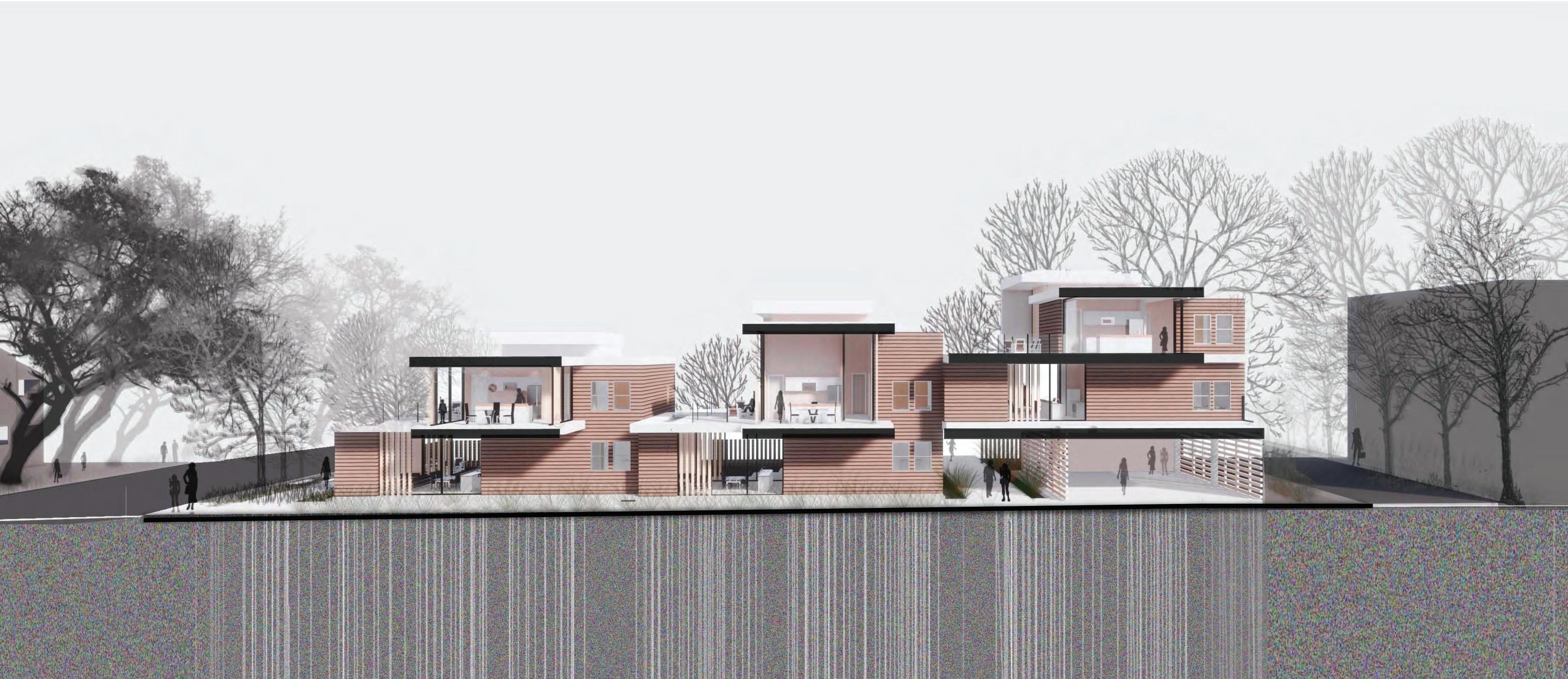
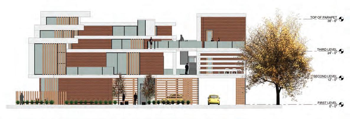
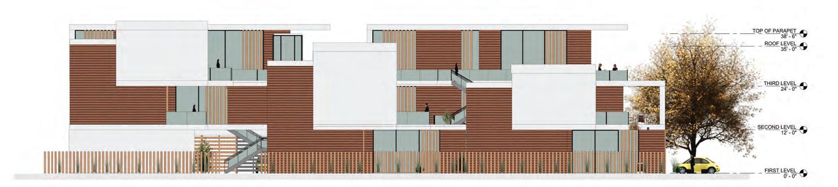
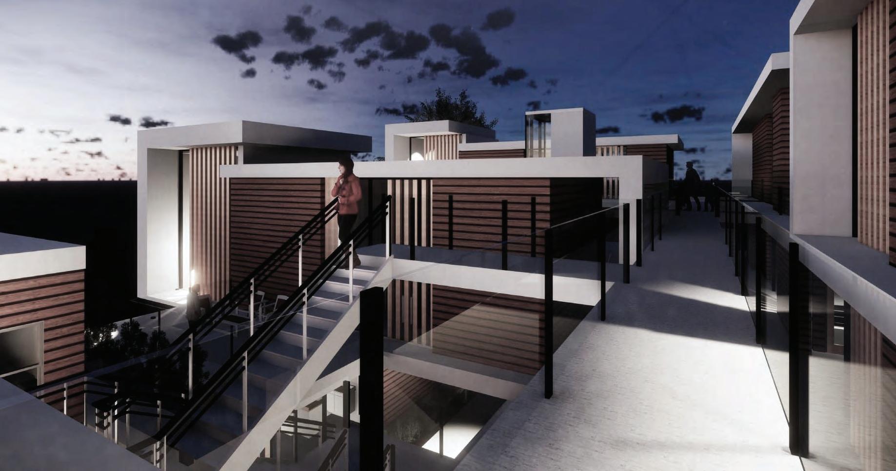
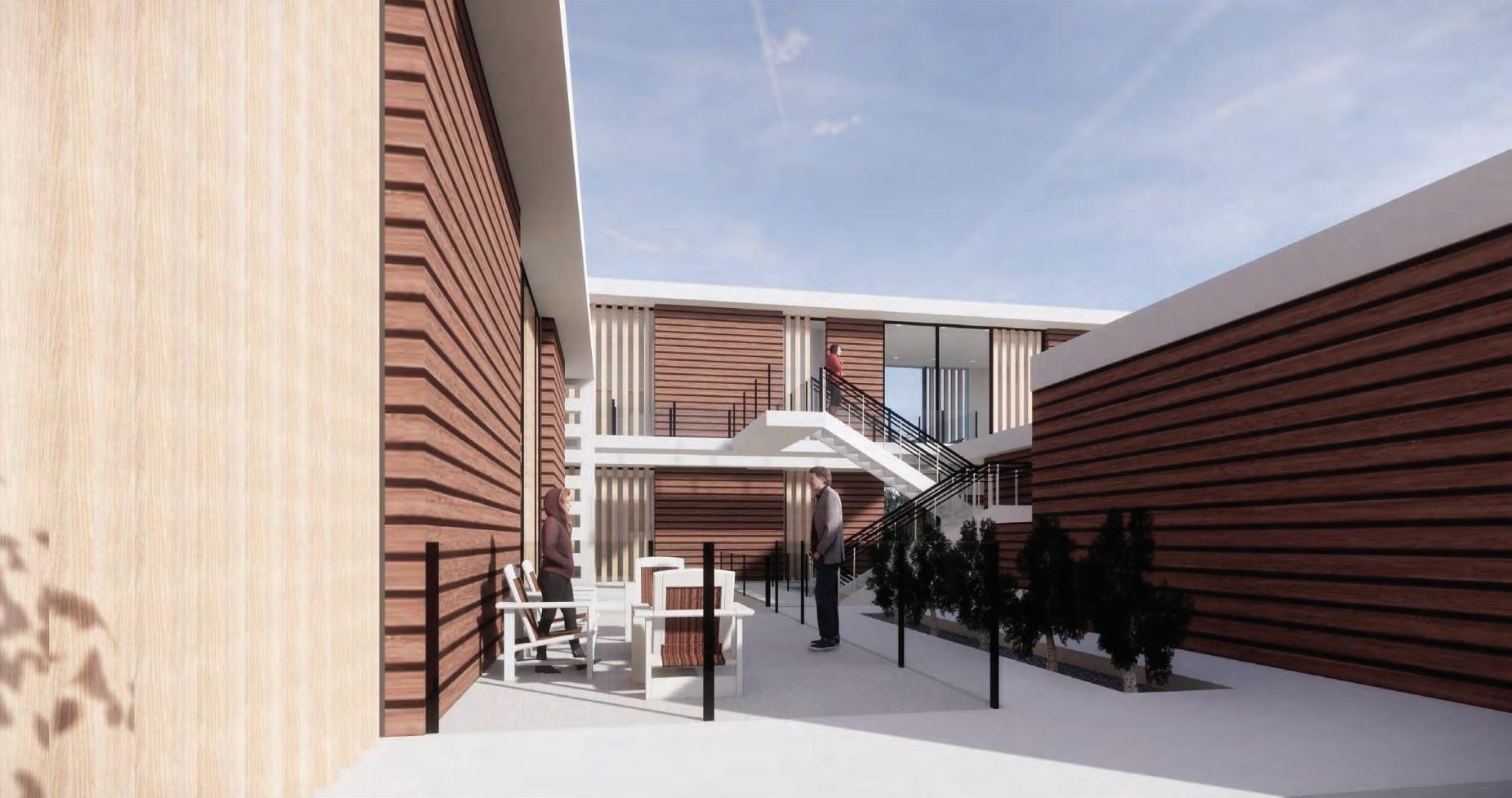
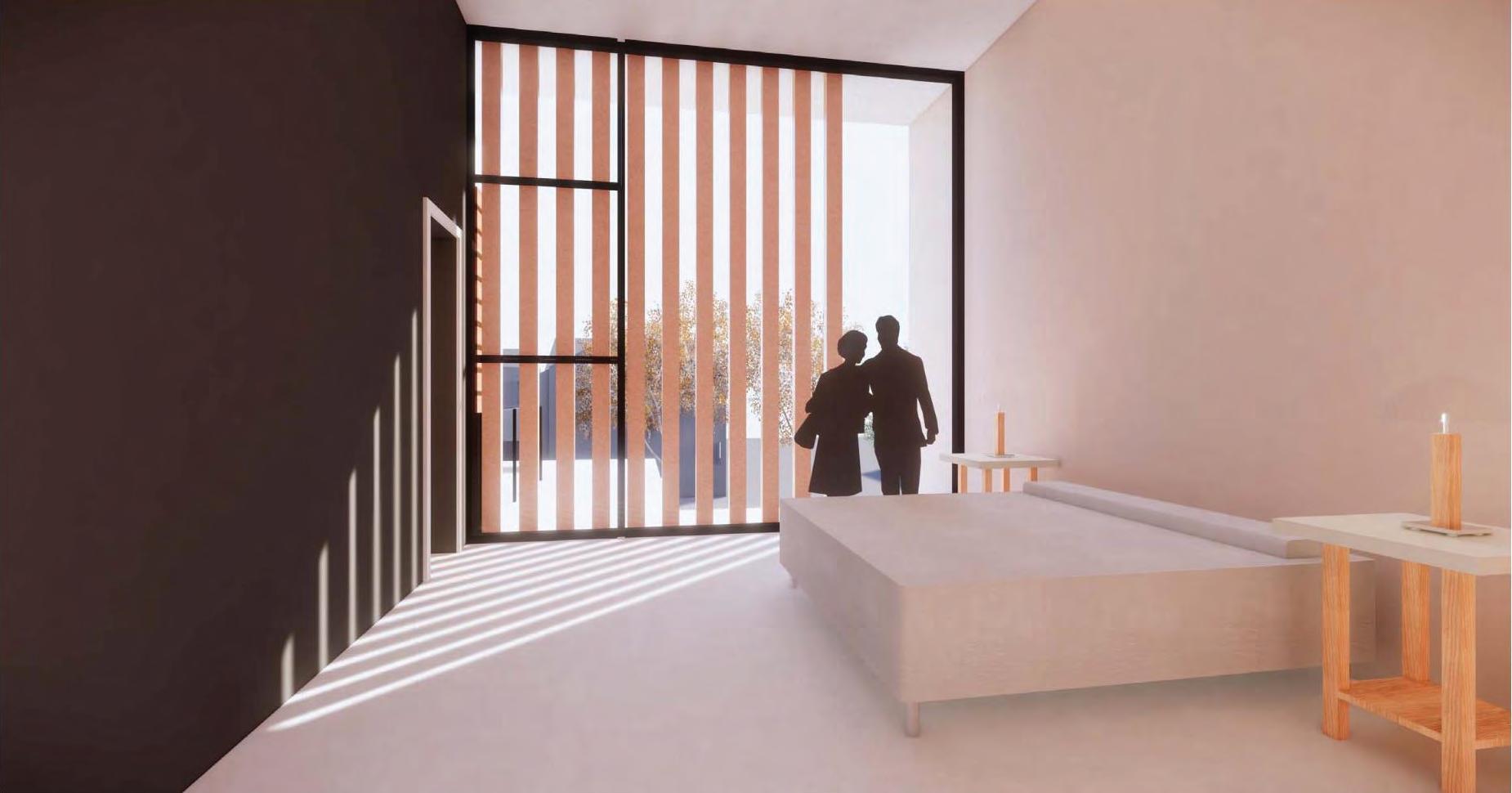
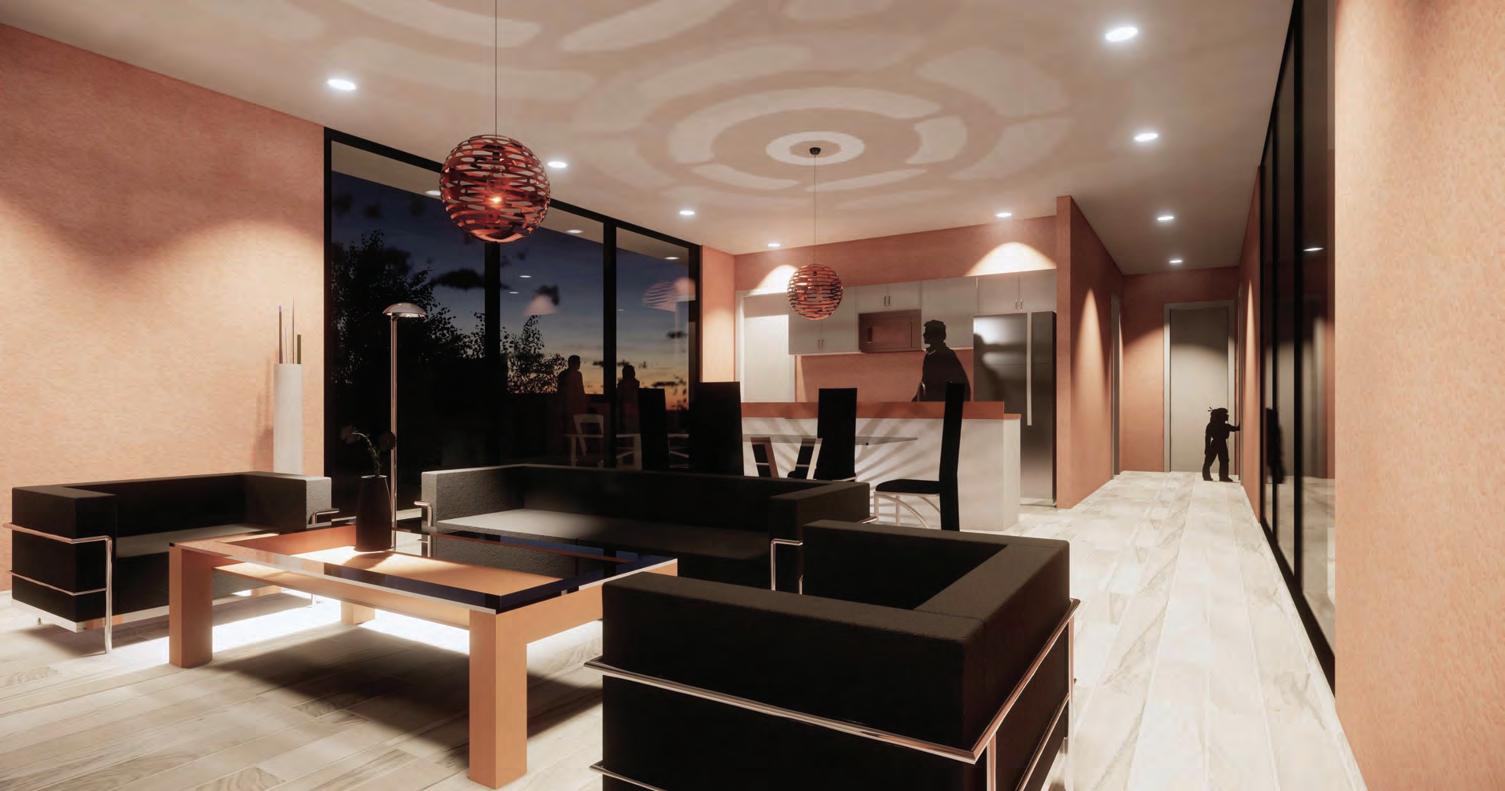
A 1,100 sq. ft to 1,300 sq. ft unique ten semi-detached living spaces are located at Highland Park in Los Angeles, California. The design draws on privacy as a main concept by creating private entries, private outdoor spaces, and terraces. At the same time, the community is strongly highlighted by accommodating a multipurpose community room and designated communal outdoor spaces such as playgrounds and barbecue areas.
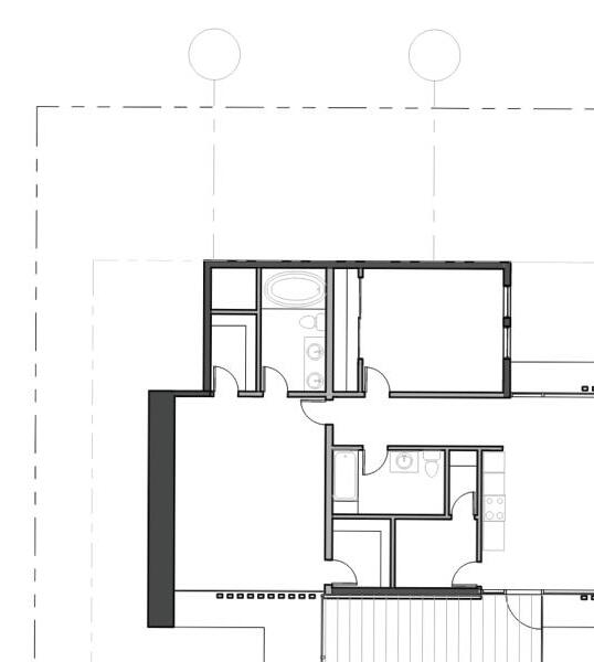
The unit type configuration is relatively simple: a bar and an L-shaped one-story unit that is staggered, rotated, or flipped to create private entries and private outdoor terraces. The housing complex has two entries, one from the main street and a secondary entry from the alleyway. A community center room and a private parking structure on the ground level are used as podiums to achieve the hierarchy and as a way to bridge some of the L-shaped units across the main entry pathway.
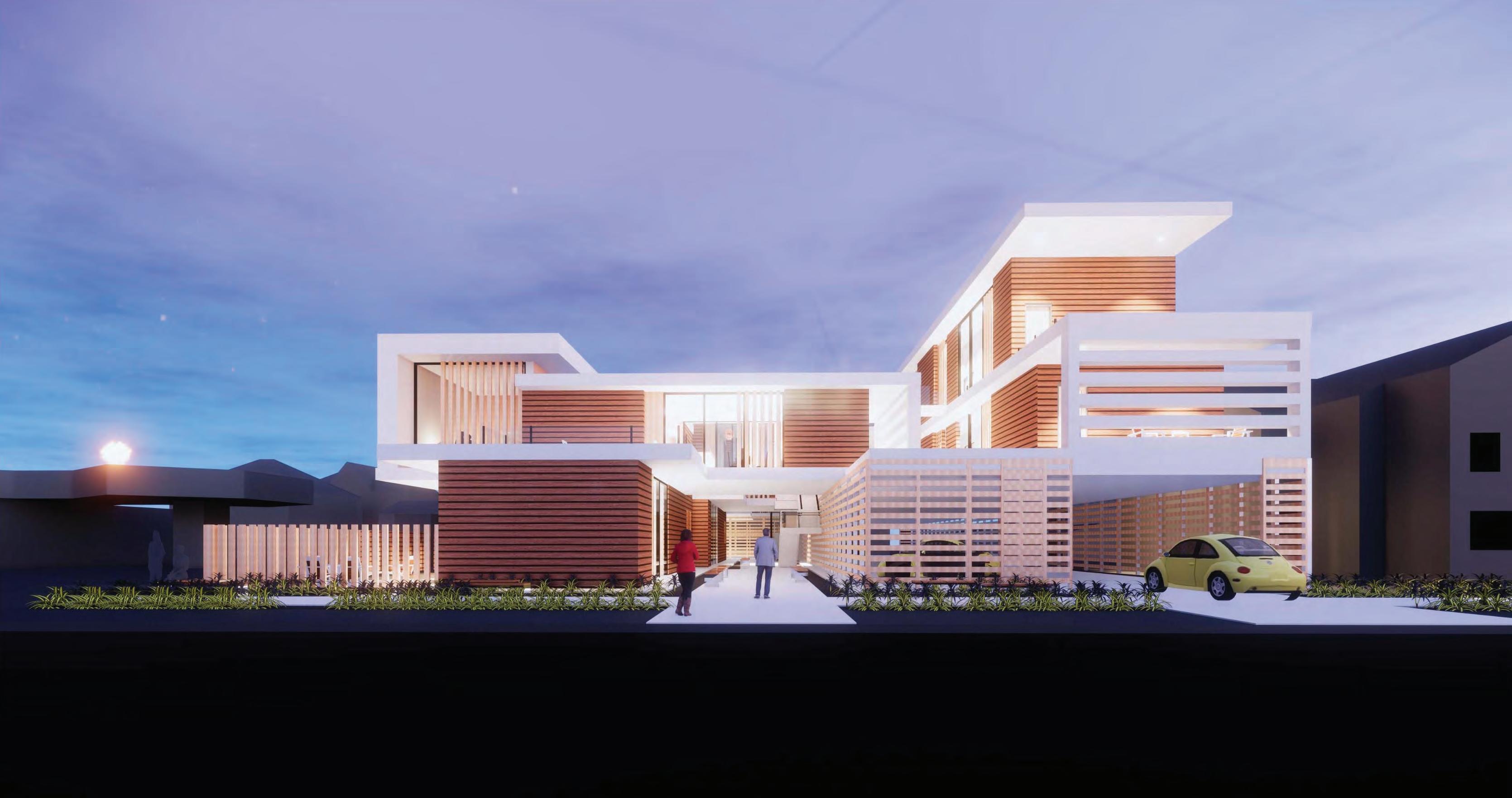
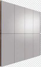
For constructability, the project uses fiber cement boards, wood siding panels as the primary materials for exterior cladding, and perforated wood panels for the parking structure and the community room.
Academic Individual Project: An integrated design studio incorporating architectural aspects with structural, mechanical, and electrical in addition to code analysis. 35% of construction documents were developed in Revit and submitted as a studio requirement. Software used: SketchUp, Revit, Enscape, Illustrator, and Photoshop.
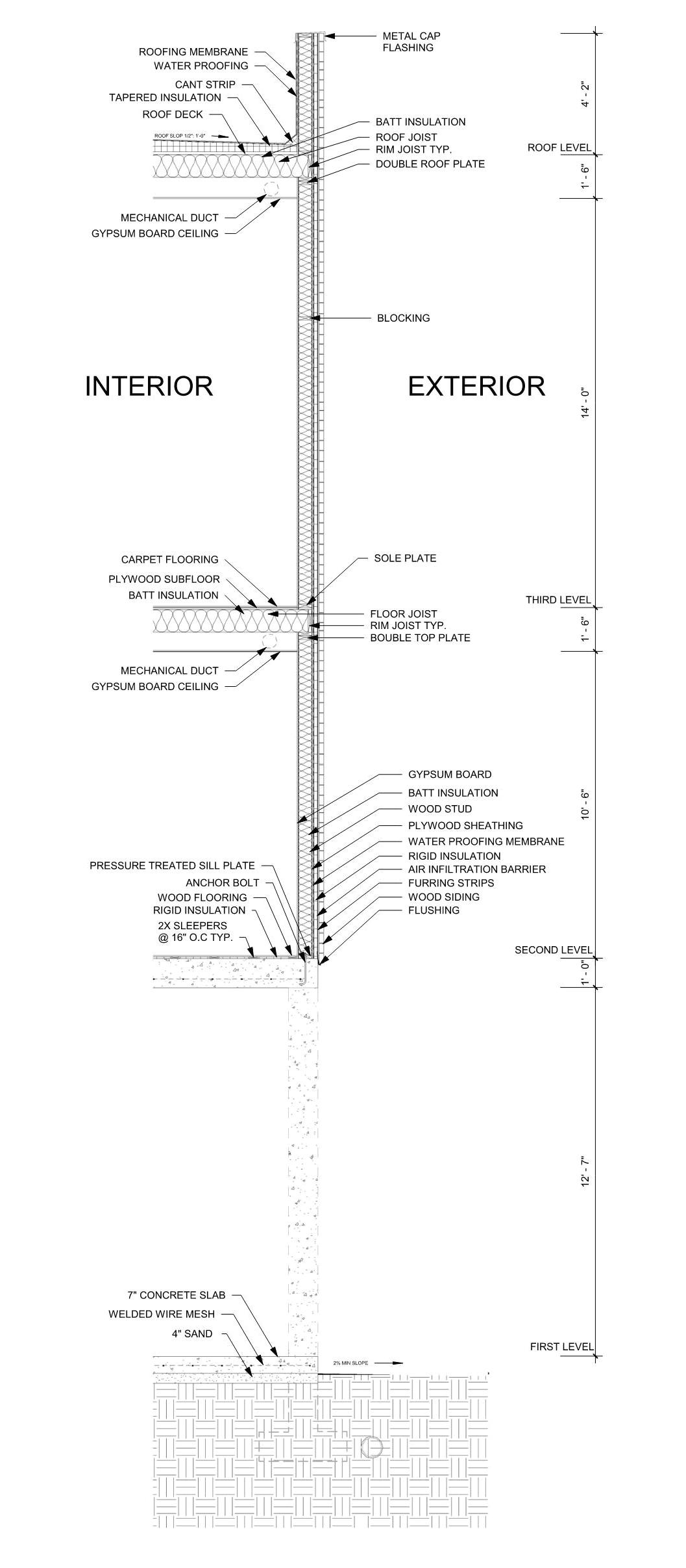


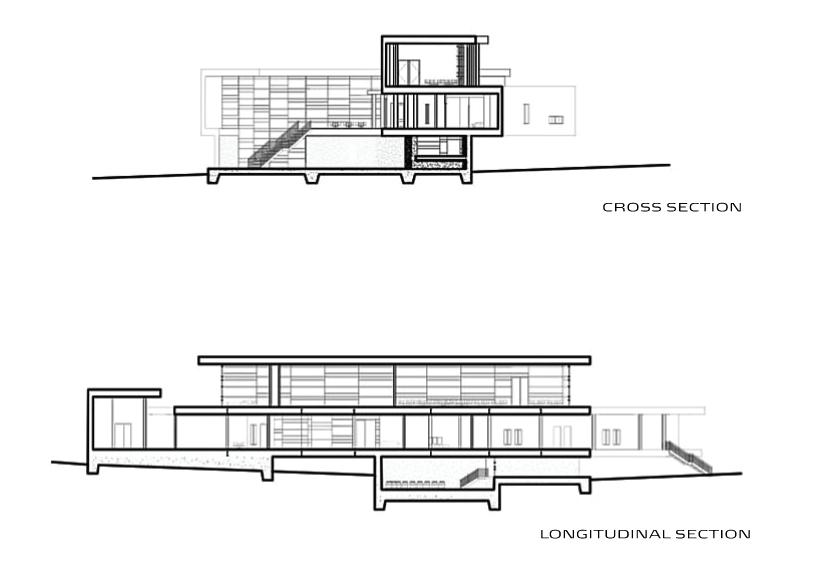
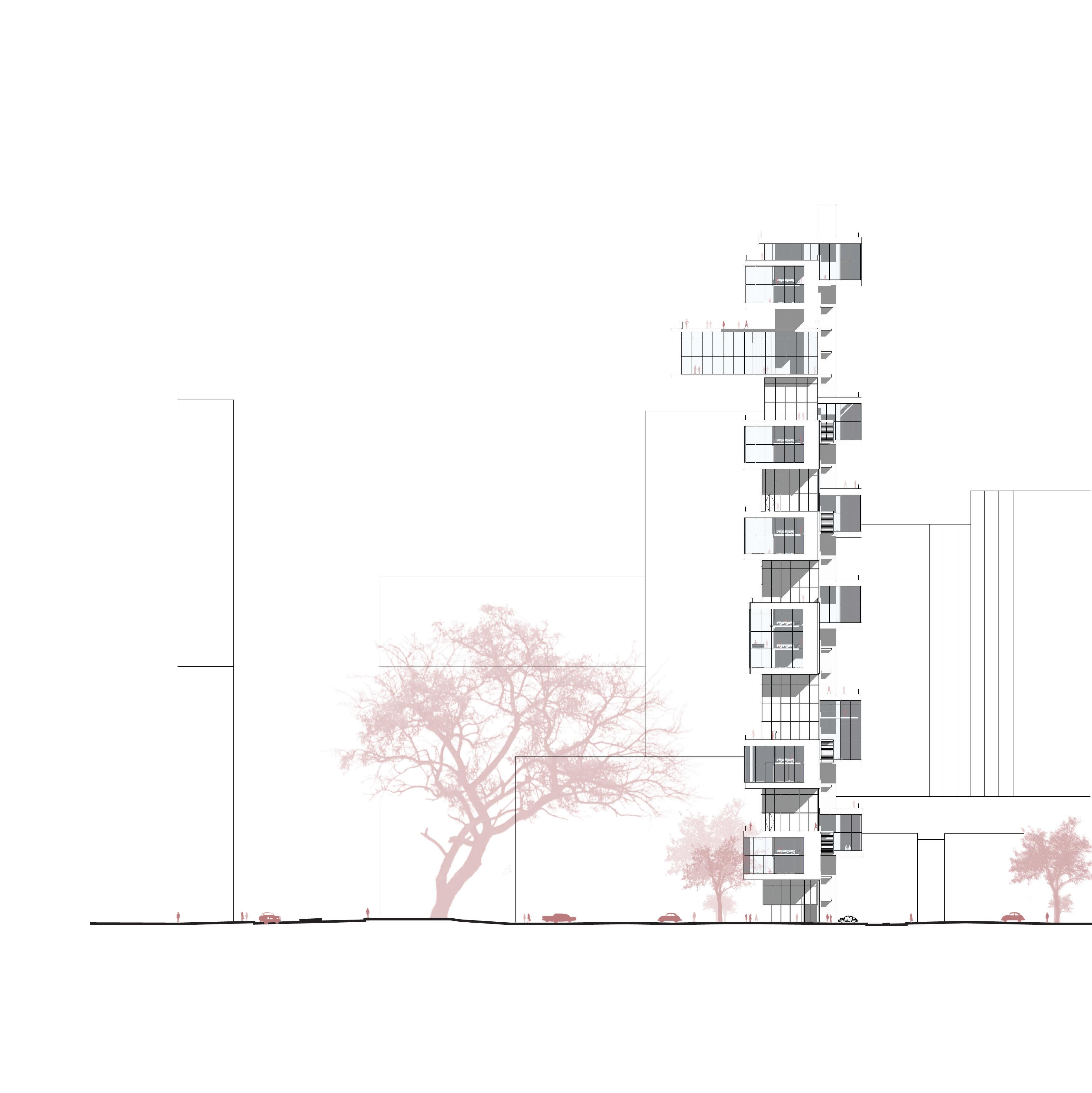
CROSS SECTION
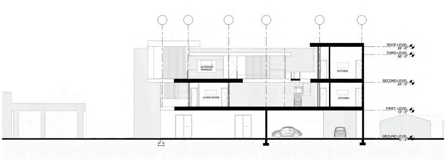
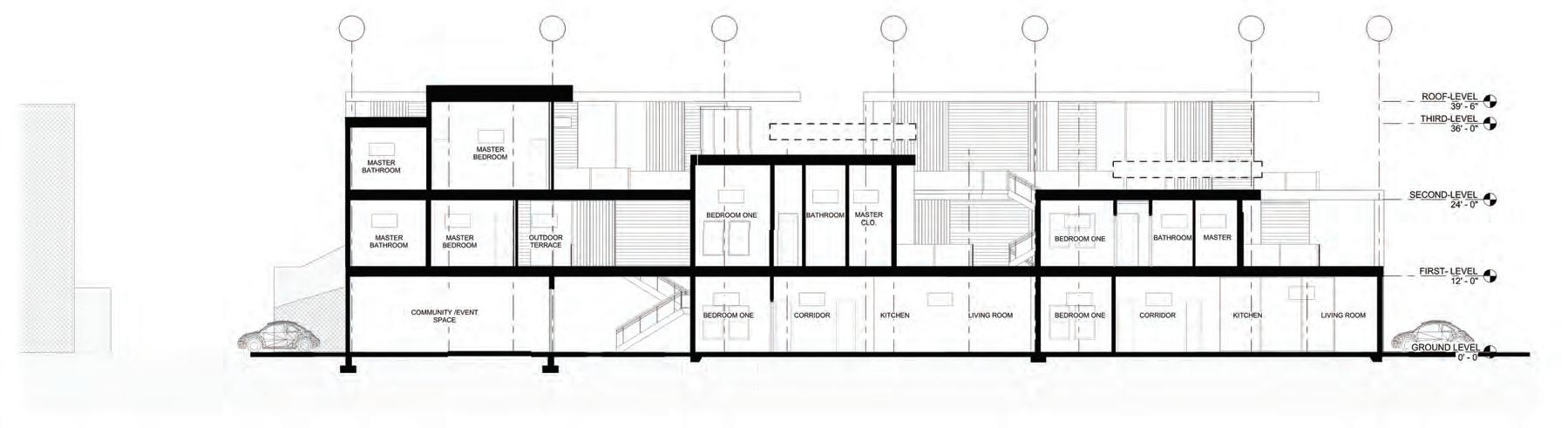
LONGITUDINAL SECTION
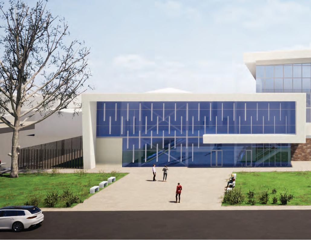
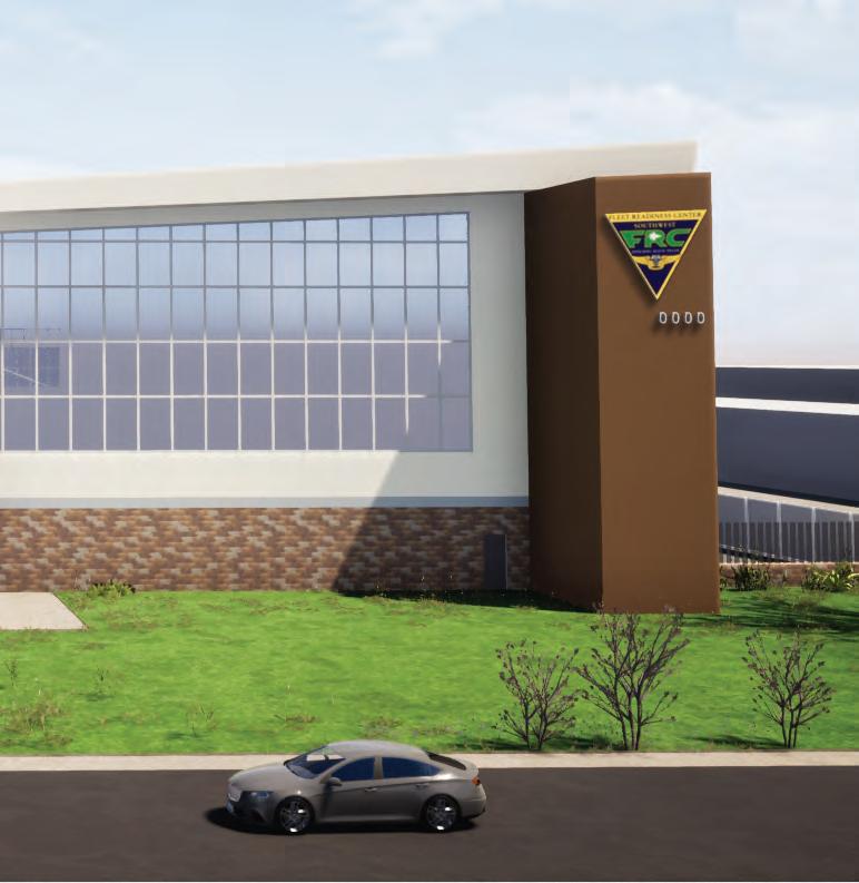
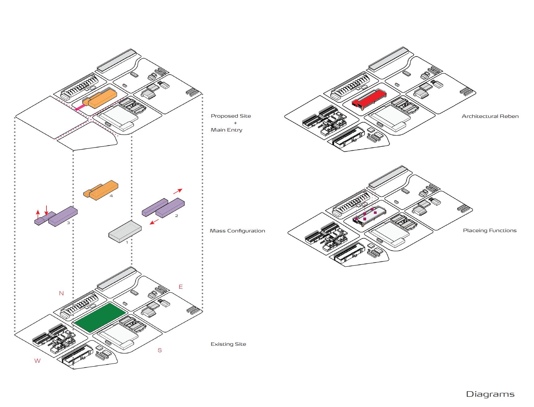
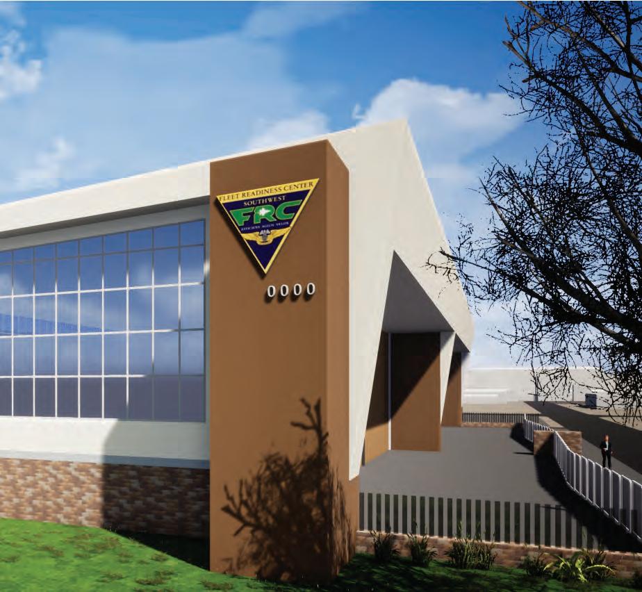
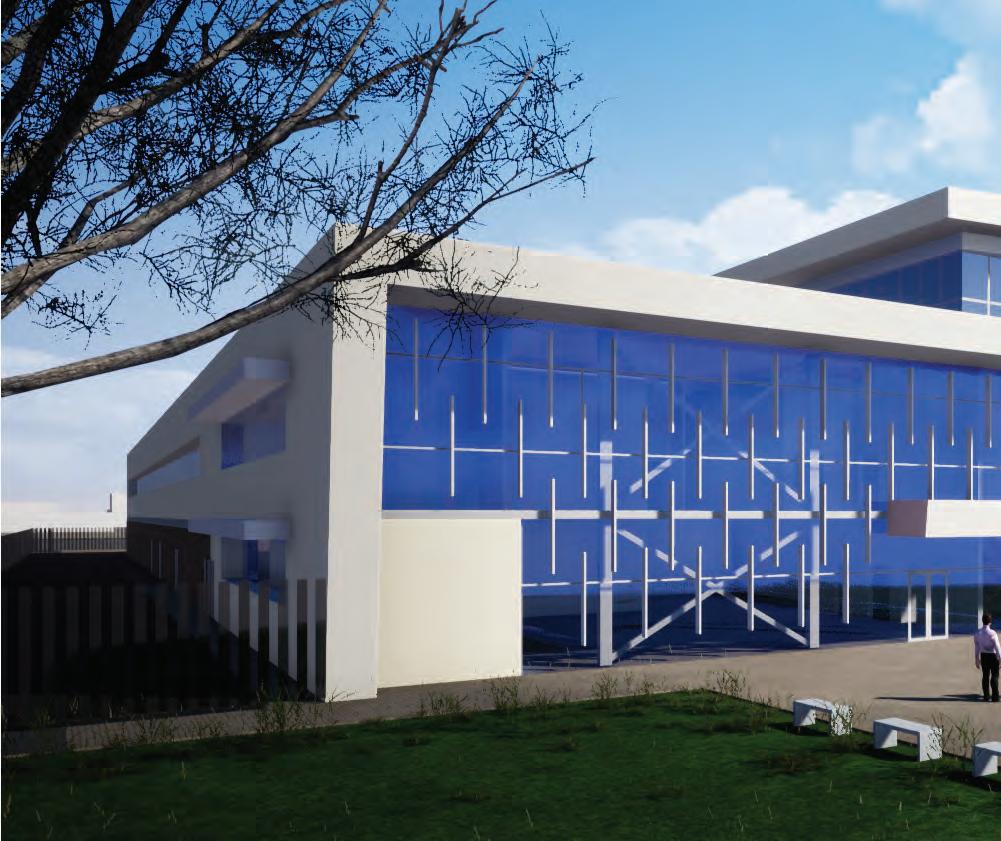
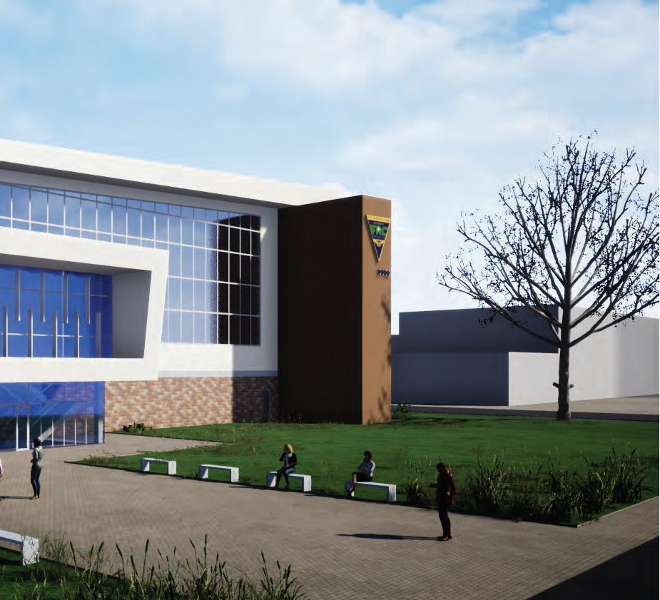
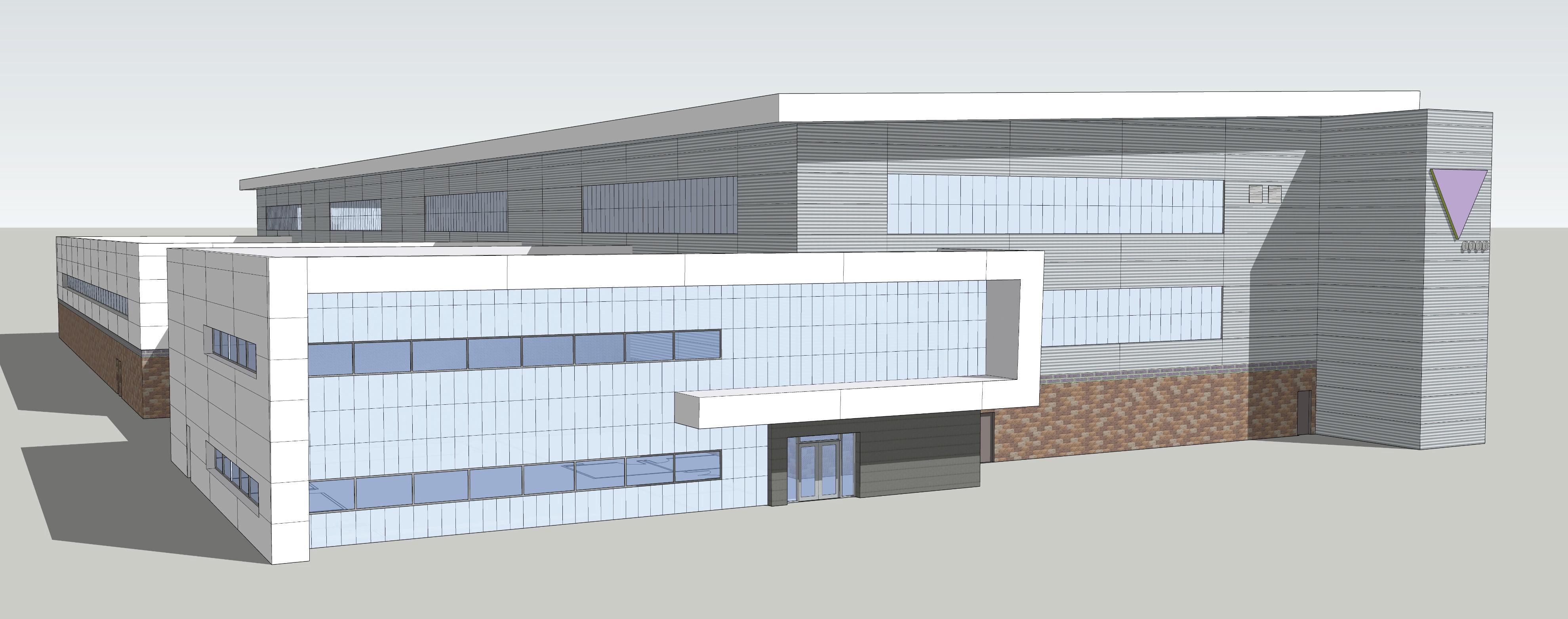
A new design concept developed for the CMV-22 aircraft maintenance hangar at the Naval Air Station North Island (NASNI) in Coronado Island, San Diego, California. The design concept developed a new vision for the federal architecture facilities by creating a non-conventional, innovative, and inspiring workspace design for the next-generation CMV-22 aircraft hangars.
The aircraft hangar program encompasses a high bay space that houses four aircraft maintenance cells, a low bay two-story space that houses the administrative office spaces, and a low bay space for aircraft machine shops and tool storage.
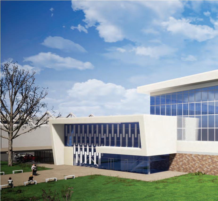
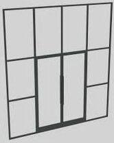
The building’s structural envelope comprises insulated metal panels with curtain wall façade for the low bay administrative offices. In the high bay aircraft maintenance spaces, non-insulated metal panels with translucent panels over CMU walls are incorporated to articulate the exterior facade and provide maximum daylighting opportunities.
The projected folding plain metal panel canopy creates a focal point to define the main entry at the administrative office area. A vertical louver system was added to the curtain wall façade to control the sunlight to the west while maintaining the visual connection between the inside and the outside.
Professional Project, Scope: Schematic Design
Role: Concept planning stage, design options, exterior massing design, revit model for BIM, coordination with consultants, construction documents productions.


Naval Facilities Engineering Systems Command Southwest (NAVFAC SW) and Naval Base Coronado have awarded the Design-Bid-Build construction for the CMV-22 Aircraft Maintenance
Hangar to the Irvine team after a successful delivery of aschematic design phase.
This 64,000 SF facility provides a viable solution to supply critical depot maintenance capabilities and execute Planned Maintenance Interval (PMI) processes.
Due to the unique functions and processes that occur within this facility for maintaining, repairing, and overhauling the new aircraft, special hangar criteria adjustments were made to address specific client needs throughout the design process, resulting in some changes compared to the first design phase.
Role: Concept planning stage, design options, schematic design, design development, design compliance, value engineering, revit model for BIM, coordination with consultants, convening upon review meeting and progress update, full construction documents production, vendor and material selection per contract terms, construction administration of RFIs, change orders and submittals, job captain.
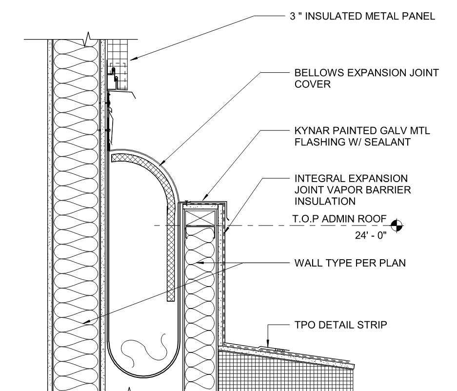

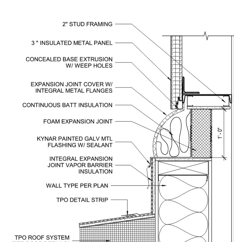

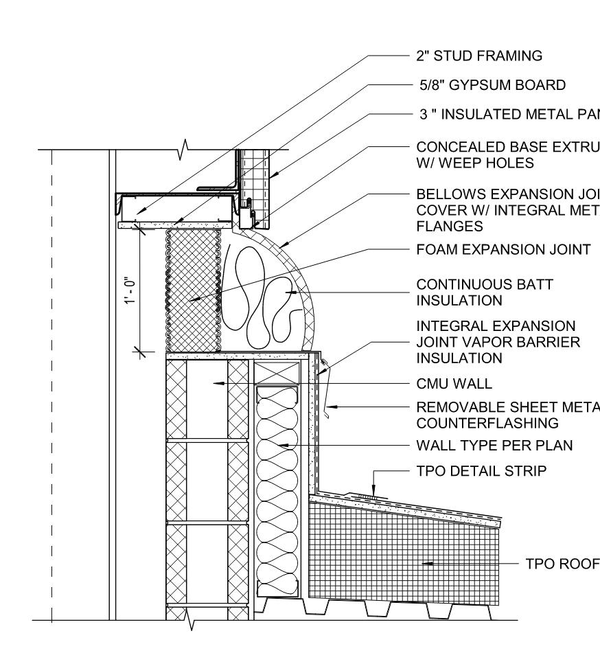
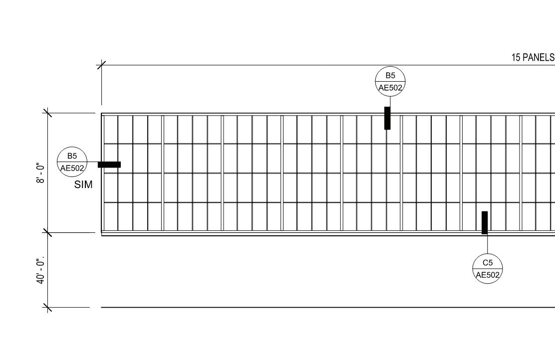
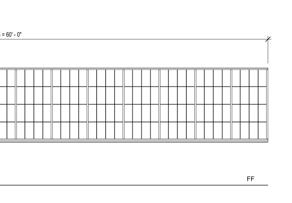
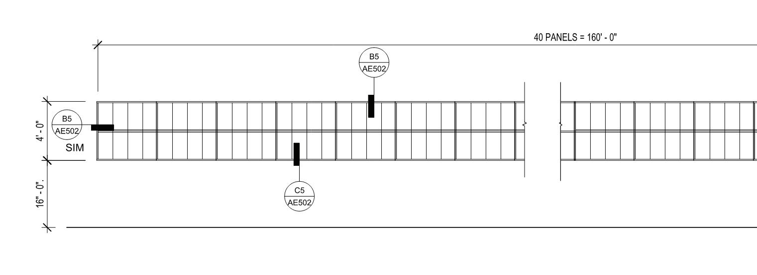
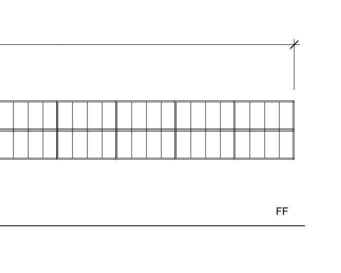
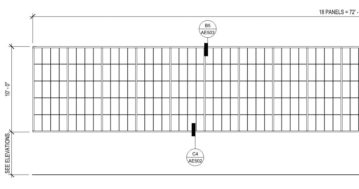
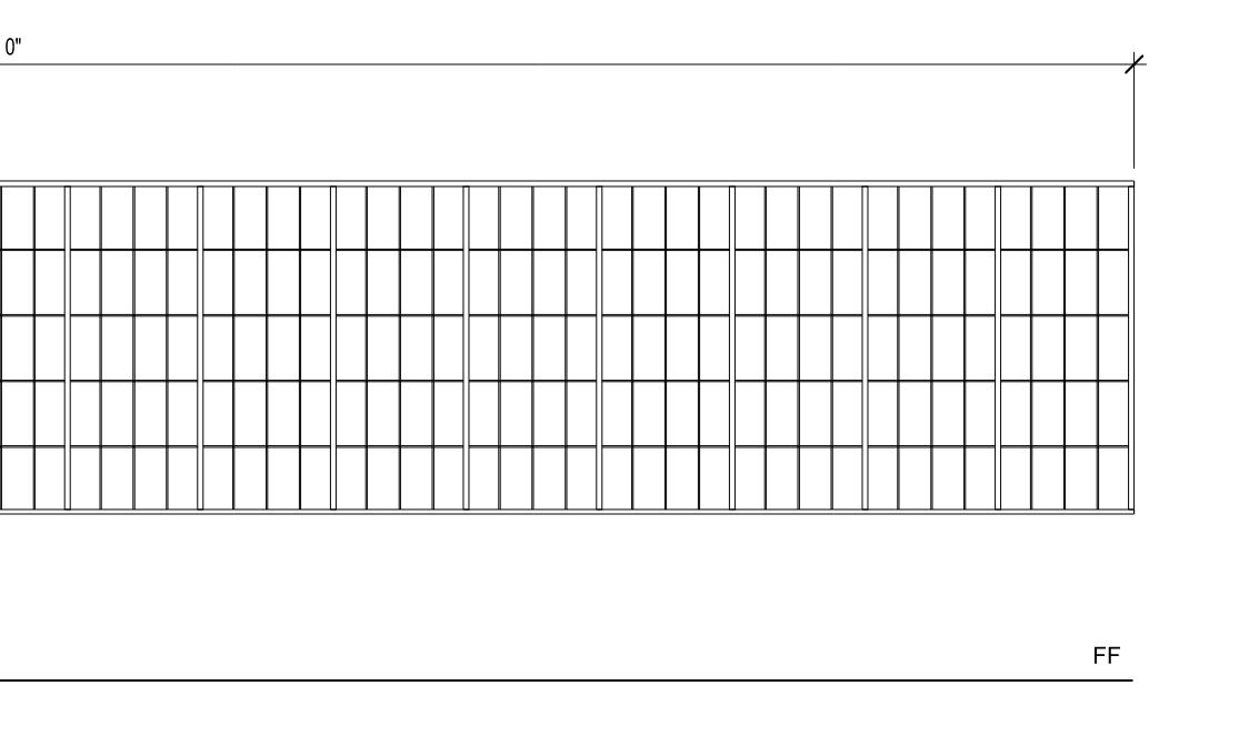
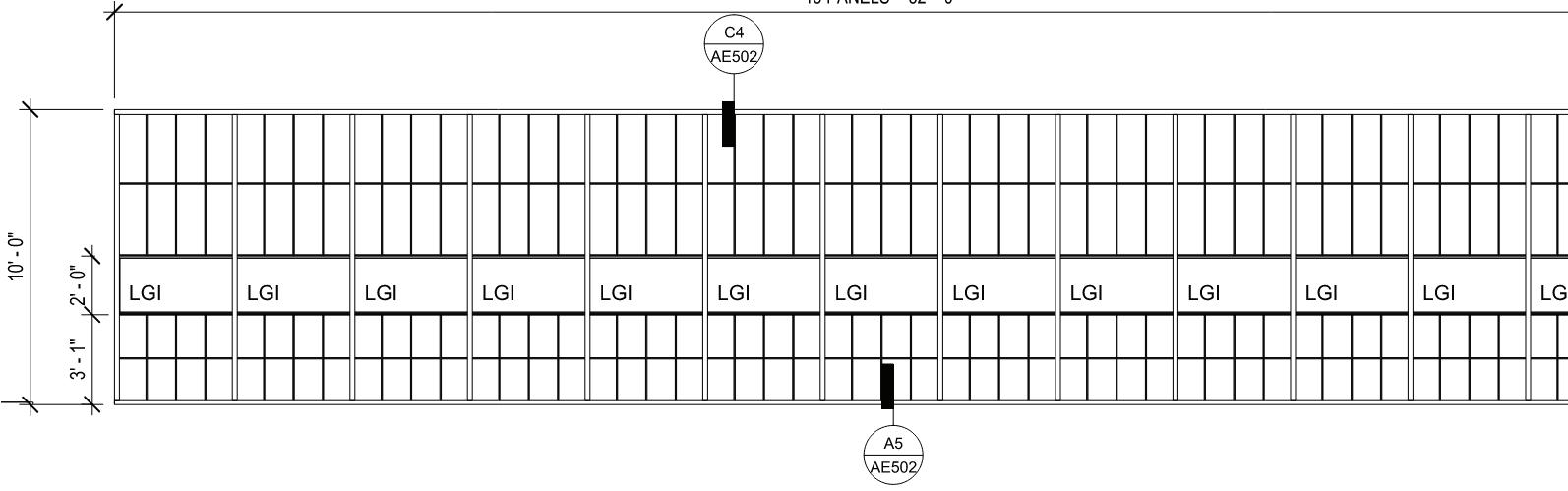
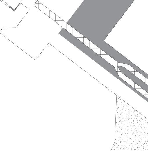
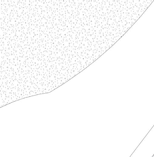
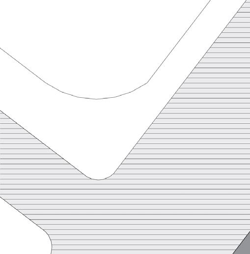
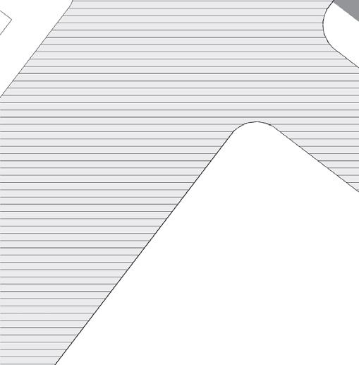
 EXPANSION JOINT BETWEEN TWO WALLS
EXPANSION JOINT AT METAL PANEL
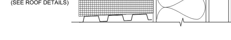
EXPANSION JOINT AT CMU
EXPANSION JOINT BETWEEN TWO WALLS
EXPANSION JOINT AT METAL PANEL
EXPANSION JOINT AT CMU
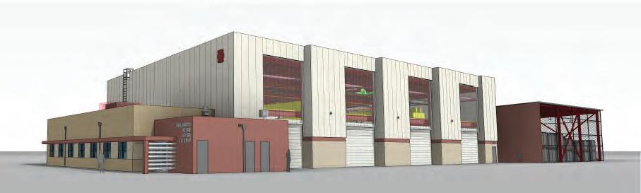
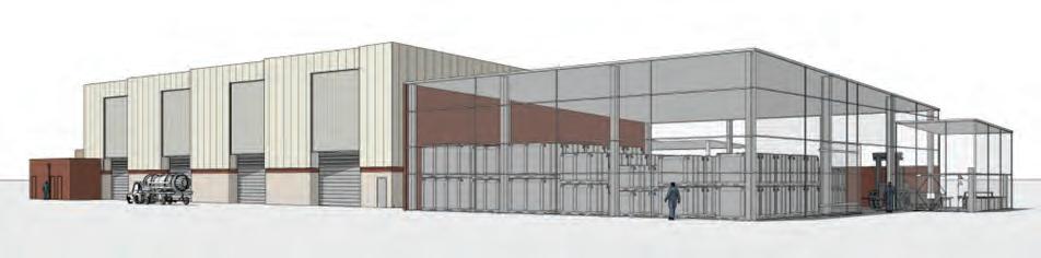
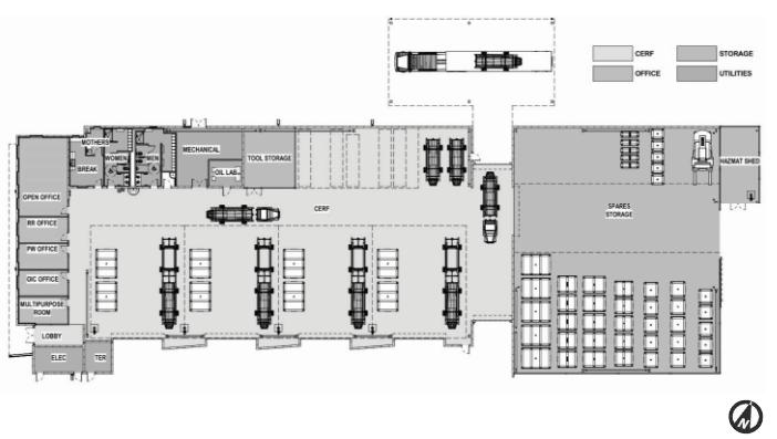
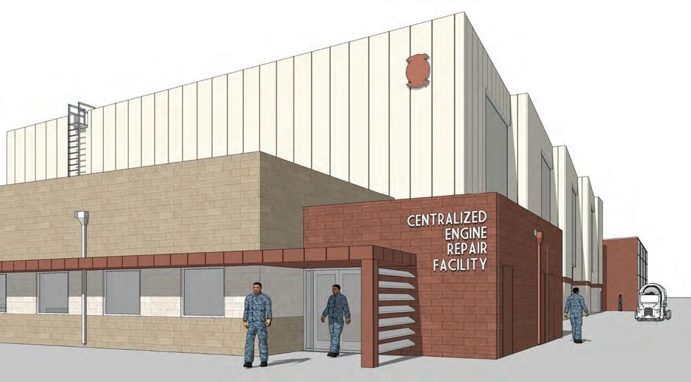
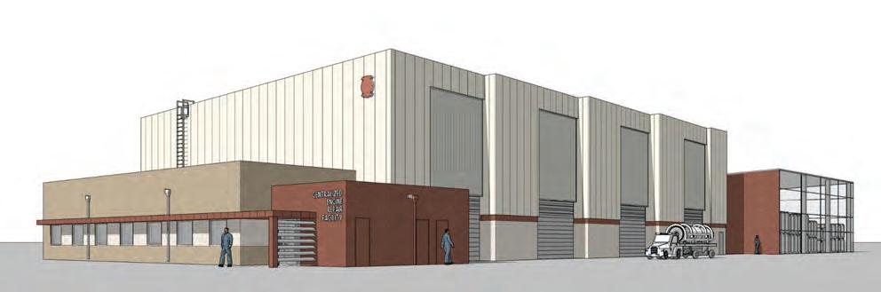
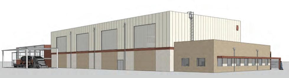
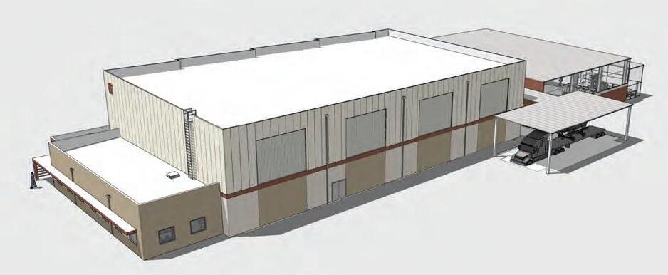
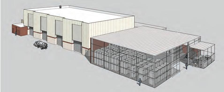
A new centralized engine repair facility for the Naval Facilities Engineering Systems Command Southwest (NAVFAC SW) is designed to support the F-35 mission at Marine Corps Air Station (MCAS) Miramar in San Diego. The design aims to improve the quality of life for maintenance personnel, improve the flow-through of engines, and inspire a connection to the F-35 mission at MCAS Miramar by visually representing the futuristic capabilities through the creative use of modern materials and forms.
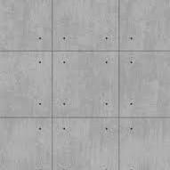
The one-story facility encompasses a high bay, four-engine maintenance bays with space for tool storage, and an oil analysis lab. A low bay, administrative offices, and personal support spaces. An open-air high-density stacker storage system. In addition, a covered outdoor loading dock with a 7.5-ton bridge crane is attached to the building. The building’s structural envelope comprises insulated metal panels with CMU walls for the high-bay space, incorporating translucent wall panels to provide maximum daylighting opportunities in the maintenance bay spaces. A CMU for the low bay administrative space and metal panel canopies to define the main building entries.
Professional Project - Scope:Full Design Services
Role: Schematic design, design development, coordination with consultants, revit model for BIM, construction documents productions, vendor and material selection per contract terms, job captain.
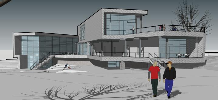
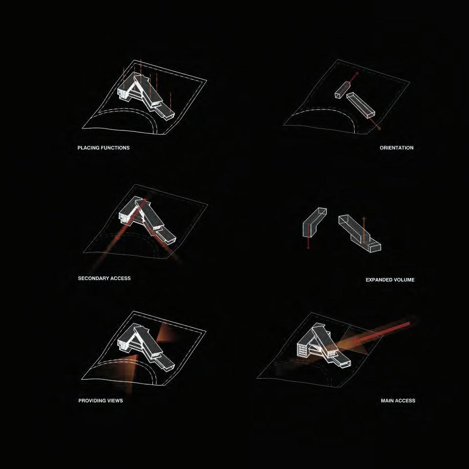
A new facility that functions as a winery and venue for a wine-country experience will be located in Temecula, California. The land suggests, speaks, and offers advice on how to produce the most expressive wine, using the natural site slope of 20 feet as an inspiration for the design utilizing gravity; a wine flow with gravity.
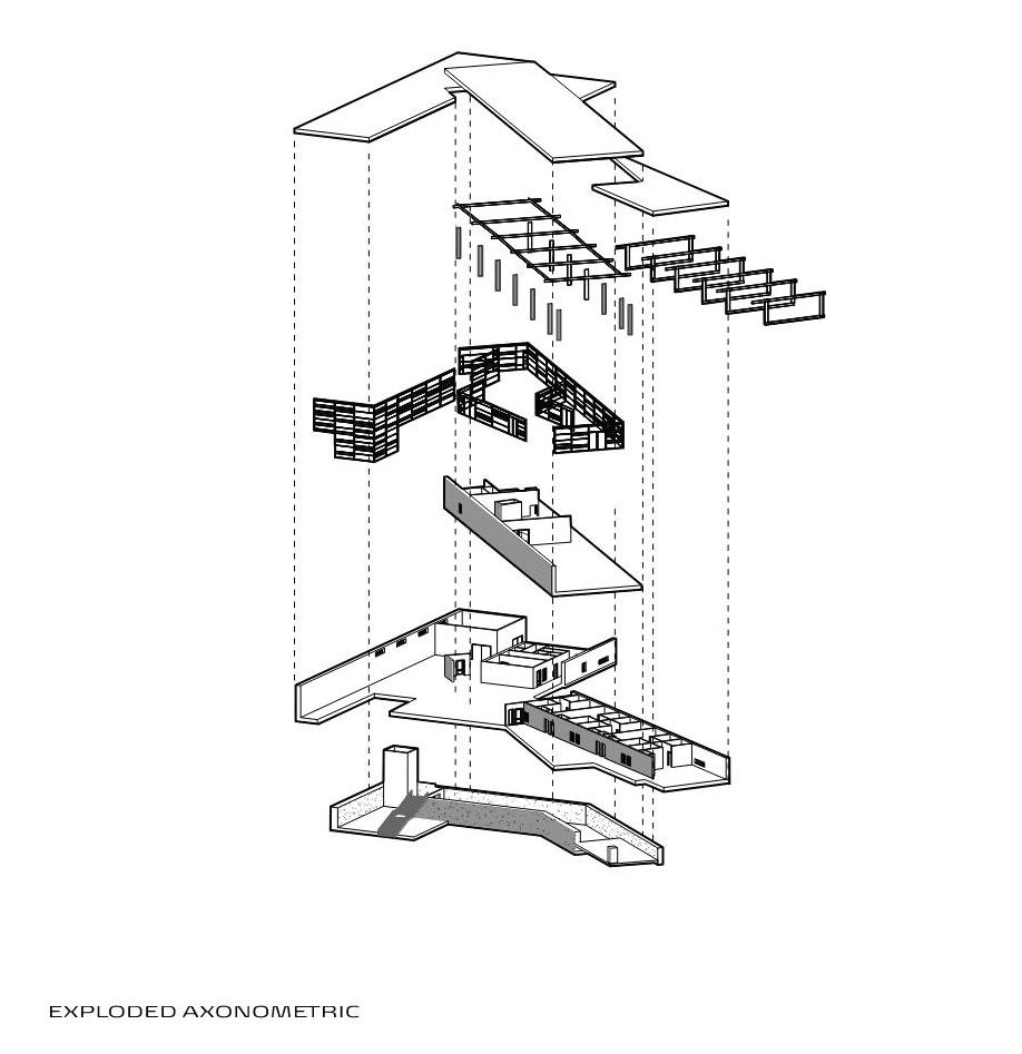
The program for the winery is relatively simple: a two-story building with a half basement. It is mainly a two-bar-type building with structural spans across its width. One of the bars represents the wine-making space, which is aligned parallel with the sloped site and the existing rows of vineyards. The other is oriented and cantilevered out towards the solar geometry, to the east, and it represents the public space of the winery.
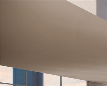
The building has transparent material with its designed curtain walls on some levels of the north, east, and south elevations, which blurs the inside with the outside environment. The south elevation is protected with deep roof overhangs, supported by an exposed steel structure system that runs through the whole building except for the concrete walls. The concrete walls placed on the underground floor provide structural and thermal performance. Lastly, CORTEN weathering steel wraps the building as a nonstructural component.
Academic individual project: 2nd year grad studio.
Software used: SketchUp, Revit, Illustrator and Phtosshop.
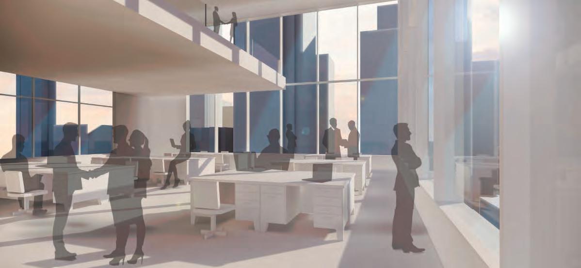
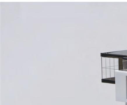
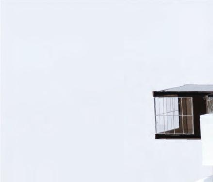
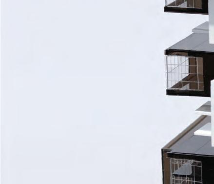
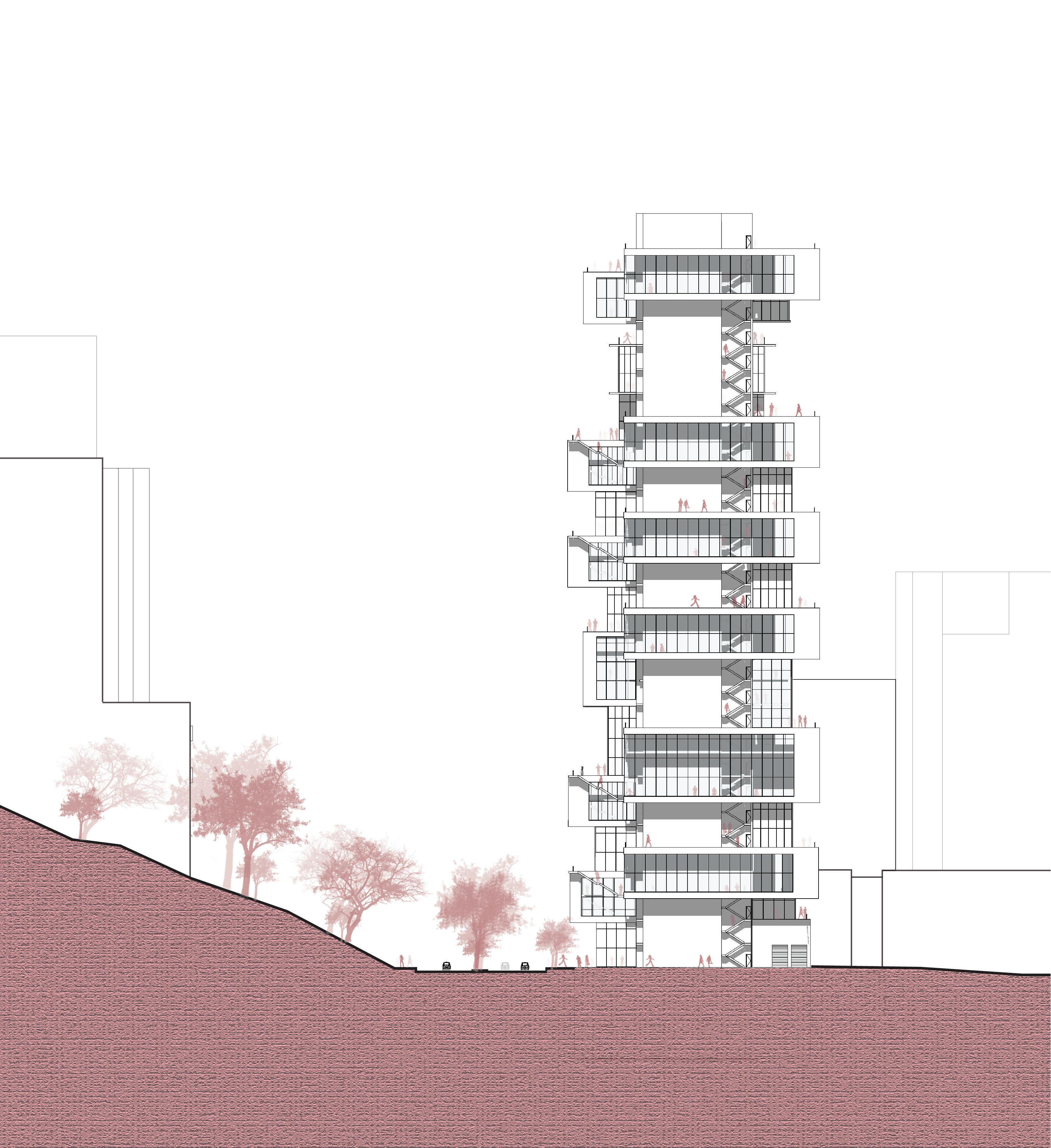
The cities we currently live in are enclosed, reclusive, and simply not open. Borrowing from ideas of Winy Maas when he introduced the notion of porosity. The future of the urban dense areas would be imagined by opening up solid blocks; by creating pores and connection between inside and outside; creating proximity and diversifying views; and by increasing daylight. Our existing solid blocks would become friendlier allowing for more interaction between the people, buildings, and the surroundings.
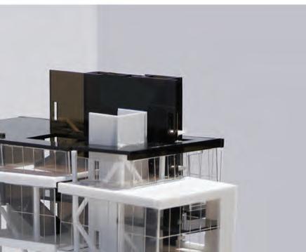
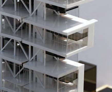
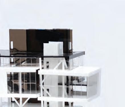
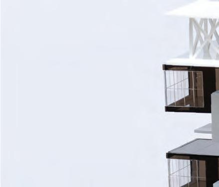
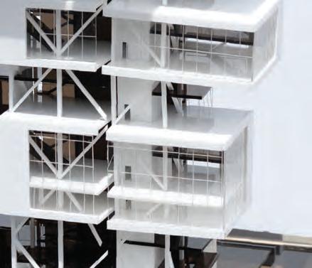
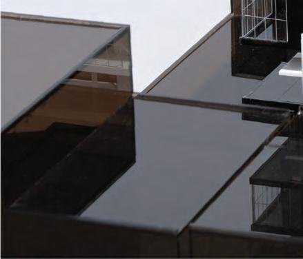
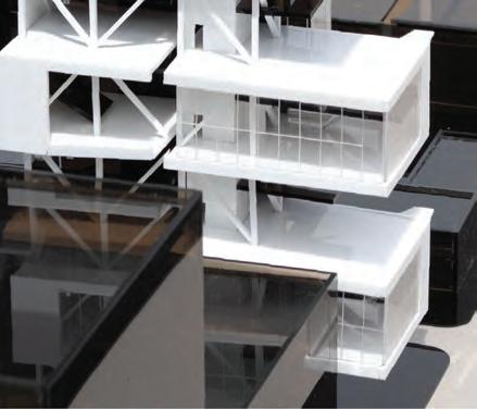
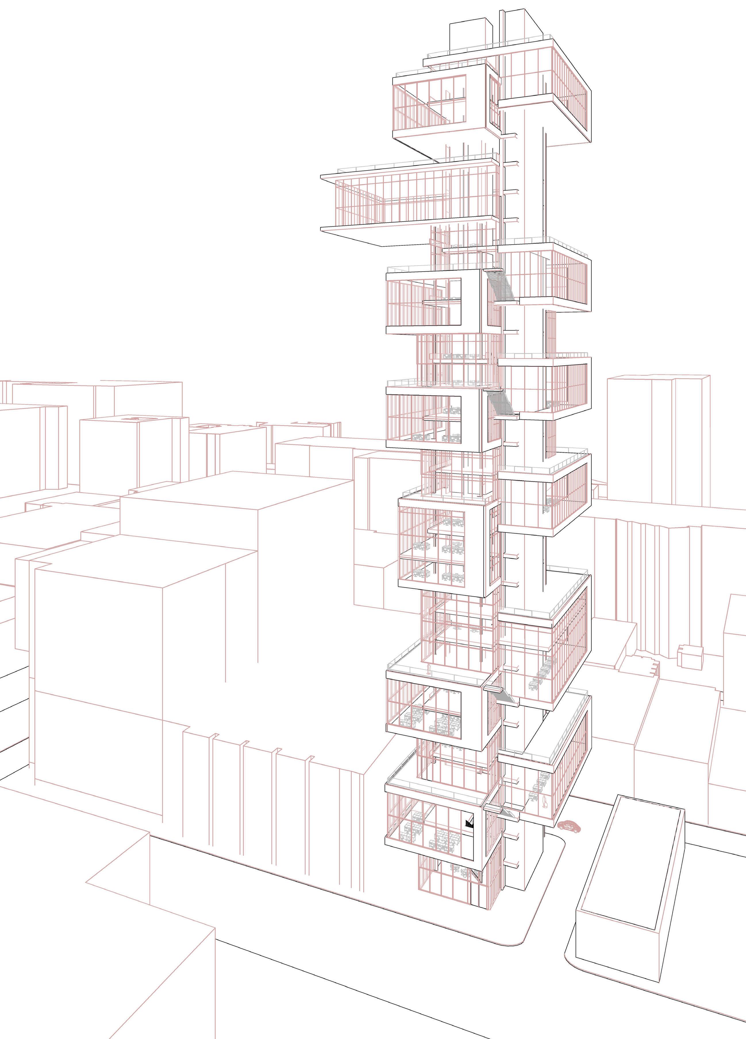
The design is driven by the idea of interlocking volumes, and dividing the tower into clusters; the mass is the general program while the void is the public space. Each cluster encompasses three floors.
By interlocking the volumes, shorter floor plates opened the possibility to maximize the natural light and ventilation. The porosity and opening up the solidity were the answer to connecting the building with visual connectivity to the street and the park. Porosity was addressed in different aspects of the project. For example, in each cluster, some void was introduced to connect two floors visually and physically and allowed for an active design that encourages people to use stairs rather than the elevator. In other areas, void was introduced to create double-height spaces that connect other floors from different sides and ensures ample natural light. I envision this methodology of interlocking volumes and porosity to be a prototype to revamp the downtown, making it more connected and more inviting to the creative class.
Academic Individual Project: Thesis Project Software used: SketchUp, Revit, IIIustrator, and Phtosshop.
(Void)
Public Space
Outdoor Terrace
(Mass ) Program
Office Space
The idea of dividing the tower into clusters was inspired by how my client, We Work, works. WeWork rents out office spaces to startups and small companies. Companies could be renting multiple floors or a small number of desks.
In my design, a typical cluster encompasses three floors and could be rented by one company or shared by groups. The building consists of six clusters and an amenities space shared by the occupants of the building and the neighboring communities. The shared amenities (projected space) encompasses a formal restaurant, gym facilities, and a daycare. The topmost floor houses the LA eye, a space for sightseeing that people can access through a special elevator
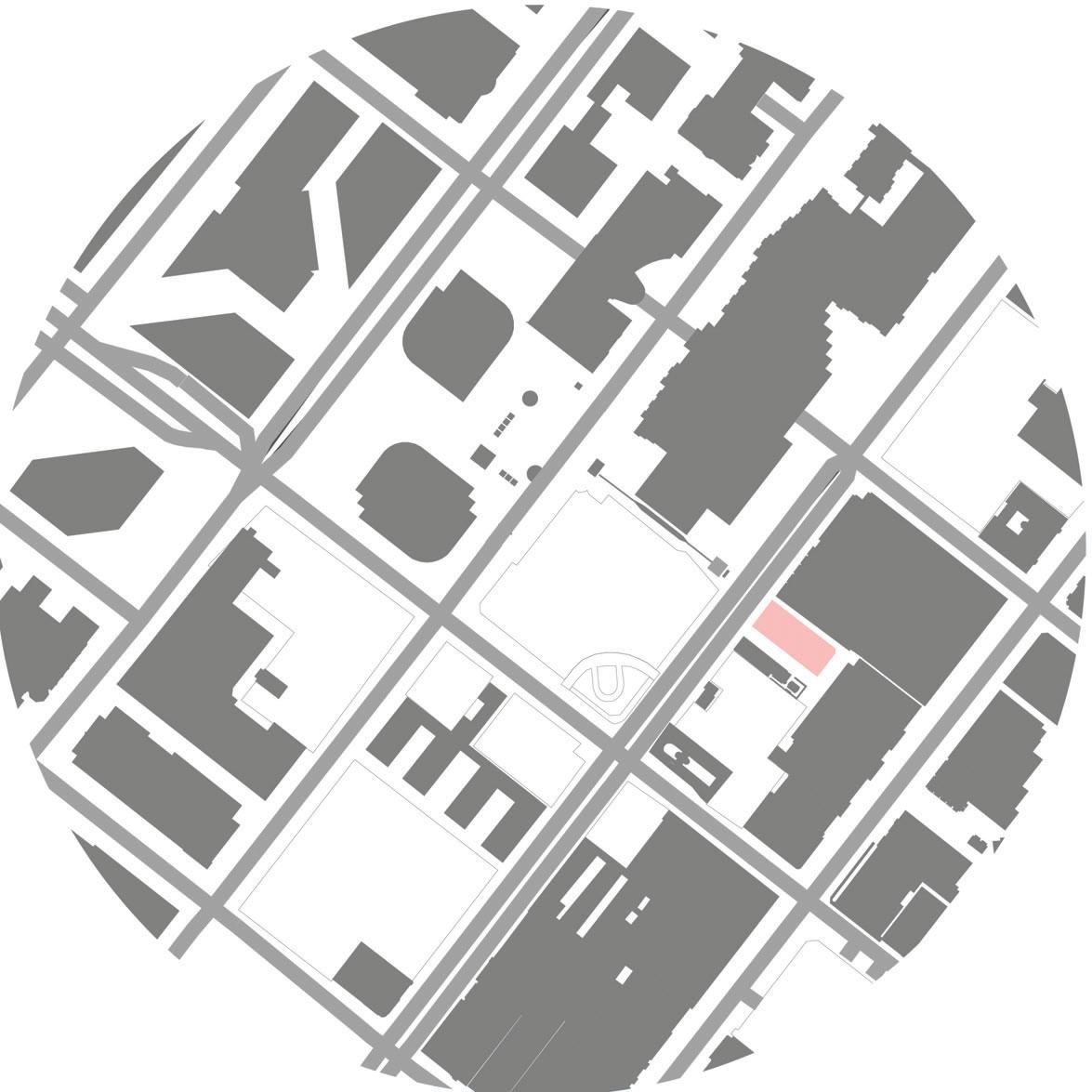
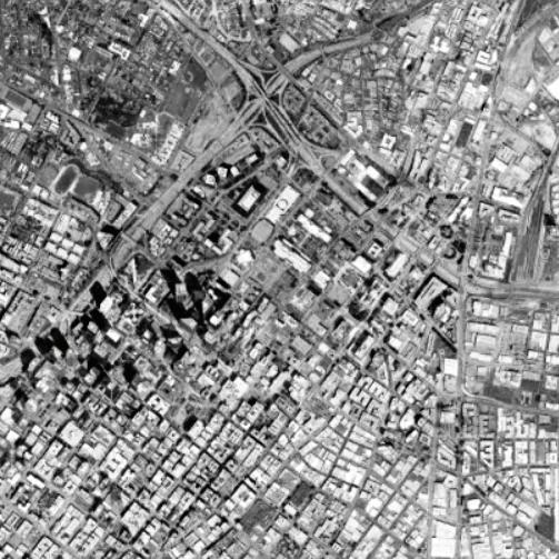
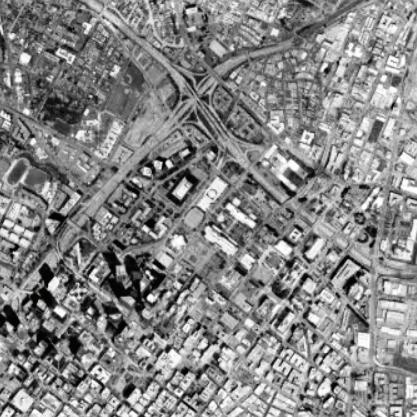
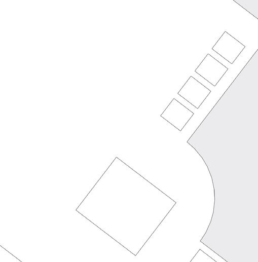
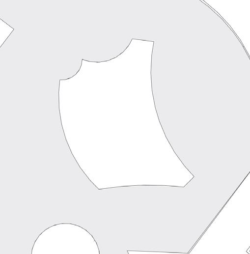
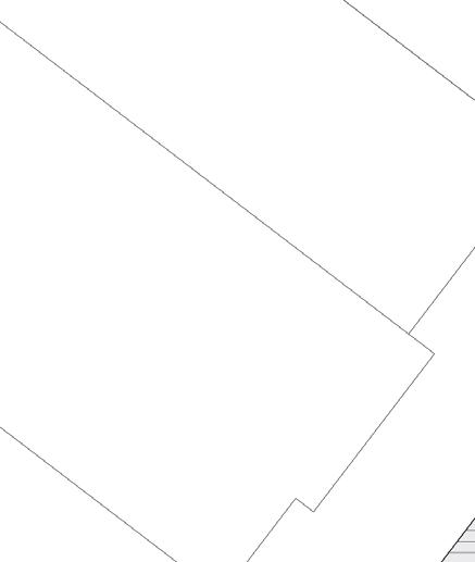
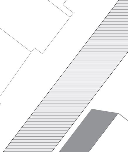
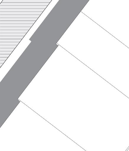
The selected site is situated across from the Bunker Hill redevelopment plan area which is bounded by the 110 Freeway on the west; Fifth Street on the south; Hill Street on the east; and First Street on the north, as shown in the map above.
Bunker Hill redevelopment plan aims to retain and expand the area as the primary office center for the region and to the improvement of the business environment by providing an attractive public realm (Masters, 2016). The site is also surrounded by prominent landmarks such as Grand Central Market, Angels Flight, and Angels Knoll Park.
(Cluster 6)
Sixth Office Space
(projected space)
LA eye + Shared Amenities Space
(Cluster 5)
Fifth Office Space
(Cluster 4)
Fourth Office Space
(Cluster 3)
Third Office Space
(Cluster 2)
Second Office Space
(Cluster 1)
First Office Space
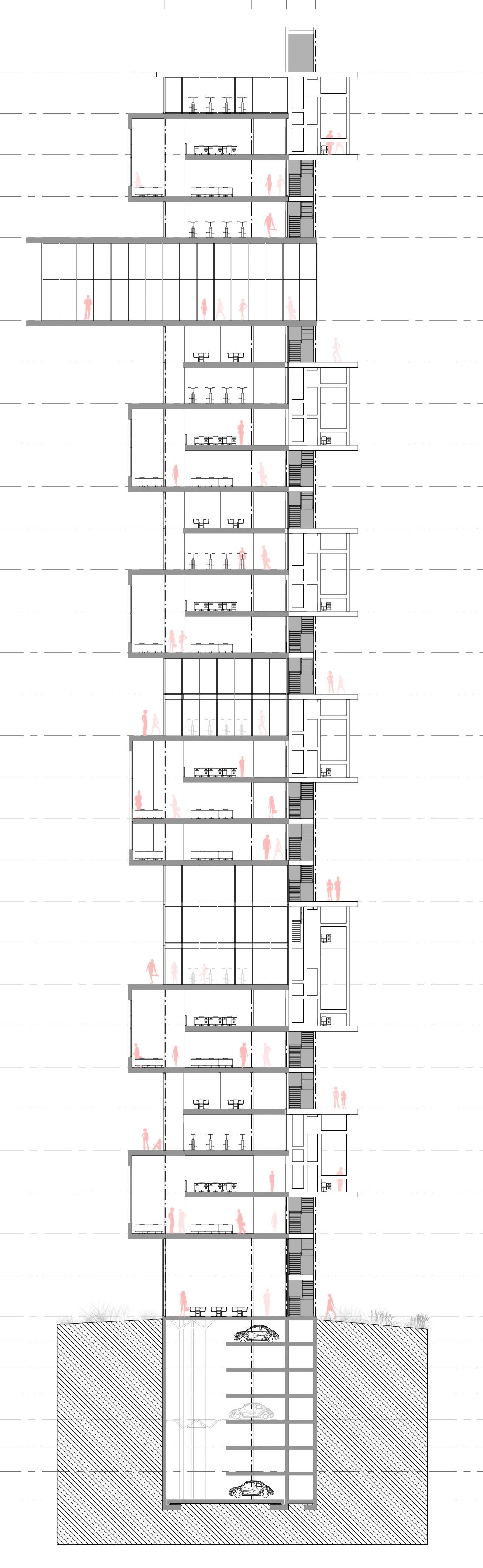


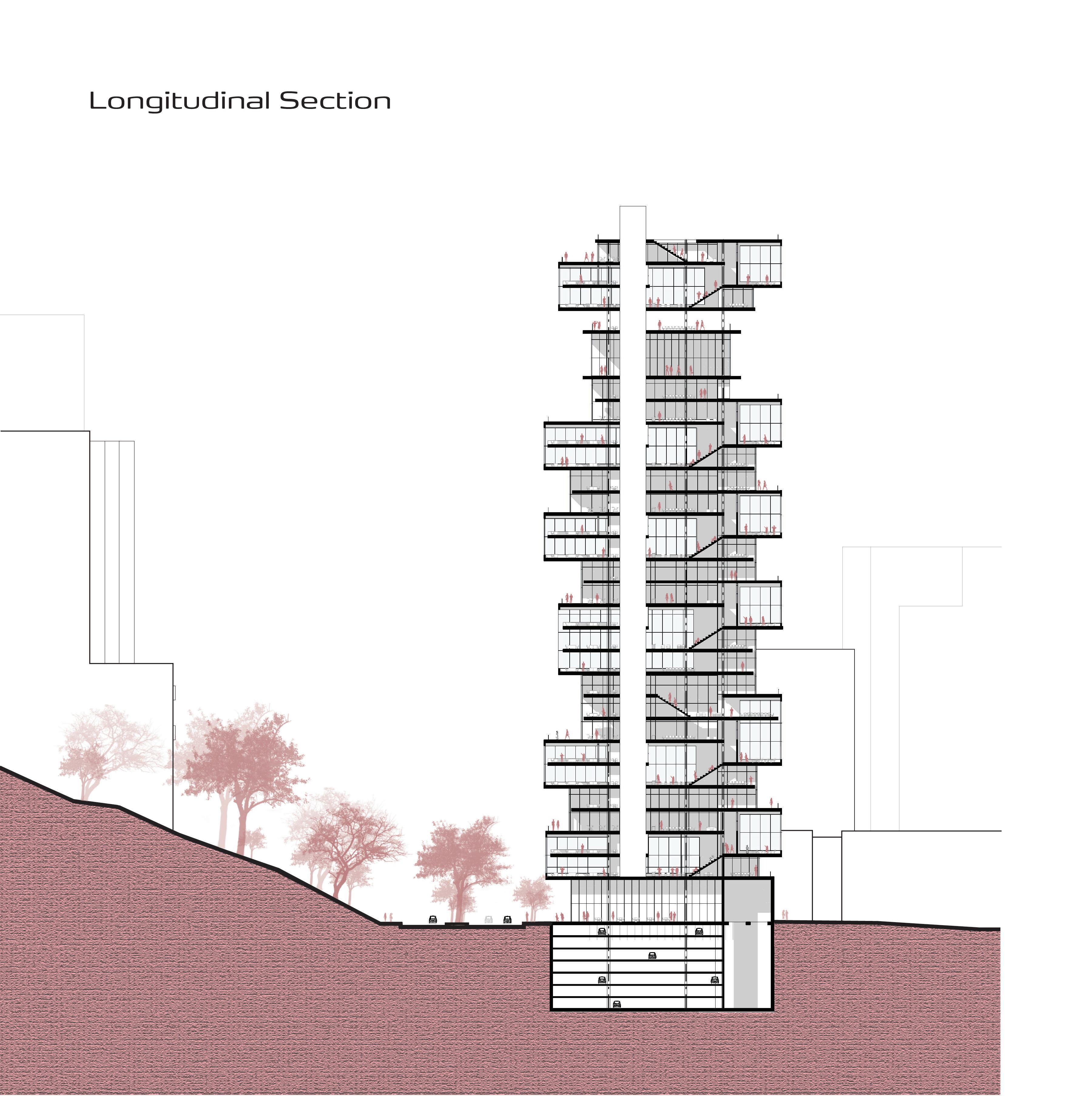
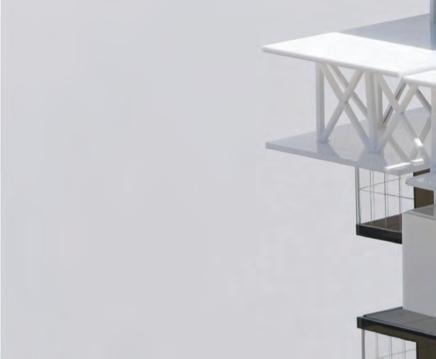
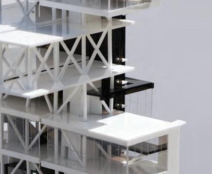
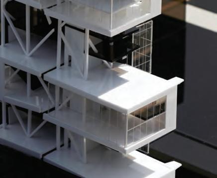
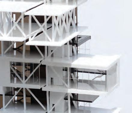
The high-rise building is Type I Construction with steel structures, concrete core, and concrete automated underground parking. The structure is governed by 24 feet square grid.
The truss-like structure system is been tie to the concrete core and anchored to the underground concrete parking generating stability, solidity and allowing to a cantilever system throughout the entire building.
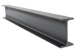
DEAD LOAD WIND LOAD WIND LOAD Section SectionSteel Wide Flange
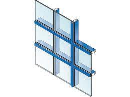
Curtain Wall System
Metal Panels
Storefront System
Concrete
Material Palette - Urban Industrial Scheme Section


Scale:
1/16” = 1’ - 0”
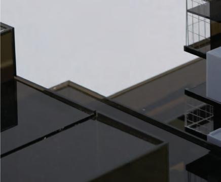
25” x 46” x 48” (W x L x H)
Media:
Acrylic, Museum board, Chipboard
Production:
Laser Cut, 3D print, Hand Assembly