ARCHITECTURE PORTFOLIO
By Alia McGurrin2023

ALIA MCGURRIN
01.05.1998 CONTACTS
email: mcgurrin.alia@gmail.com
phone: 085 800 8660
linkedin: Alia McGurrin

FEB
Technological University Dublin
Bachelor of Architecture, year 2-5
University of Limerick
Bachelor of Architecture, year 1
INTERNSHIPS
Sauerbruch Hutton
Architectural Intern
Mullarkey Pedersen Architects
Architectural Intern
WORK EXPERIENCE
Ryan and Lamb Architects
Paolo Pagliarino
Henry J Lyons
Porto
Youth Wellbeing Centre and Urban Farm pages 1 - 18
Terraced Housing pages 19 - 24
Primary Health Care Centre pages 25 -26
Bath House pages 27 - 28
Terraced Farming pages 29 - 30
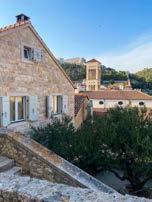
Photography page 31
Porto Academy page 32
Hand drawings page 33
Precedent models page 34
THESIS DESIGN PROPOSAL
THESIS TITLE
YEAR: 5th yr/ 2023
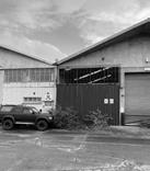
LOCATION: Dublin Industrial estate, Tolka valley
THESIS
Through my thesis research and writing I investigated the best practice for the repurposing of industrial sites and set out the four key objectives of: Reuse, Renaturing, Porosity and Openendedness. Reuse targets sustainable recycling of existing materials and repurposing of structures on site, lowering carbon emissions and retaining industrial heritage. Renaturing aims to transform the site and landscape into a place for nature to flourish once again and people to enjoy the natural mental health benefits which come with this. Porosity relates to improving circulation, connection and accessiblity. Openendedness focuses on capacity for future growth and reaching beyond the site.
1. REUSE
• Reuse of existing warhouse and site in dublin industrial estate
• Reuse of materials. eg: frame and roof truss

2. RENATURING
• Natural vegetation growth in encouraged rewilded area

• Planting of native trees and flora in gardens and courtyards
• Improved connection to canal
3. POROSITY
• Flowing/ meandering circulation through building and courtyards give a sense of a porus building in the landscape yet enclosed and secure to meet client needs for youth wellbeing center
• 4 different ways in and out - japanese rule
(i) in from broombridge road
(ii) over bridge to towpath
(iii) up boat house tower
(iv) across to park
4. OPEN-ENDEDNESS

• Connection out into tolka valley park for 5 and 10 km walks
• Connection to canal for kayaking
• Posibility for future extension/ growth of structure horizontally or vertically
• Views from lookout point at top of boat house tower out across landscape beyond the boundaries of the site give a sense of freedom and possibility

IMPACT THIS CAN HAVE
THESIS OBJECTIVES DRAWING/ SITE AXONOMETRIC
Tolka youth wellbeing centre and urban farm is designed for the client; Jamie’s Farm who provide support for disadvantaged youth’s growth and wellbeing through a programme built around farming and therapy. My proposal reuses the steel frame of an existing warehouse. I have subtracted from the structure to allow for courtyards filled with trees and relandscaped grass and permeable paving areas within the existing building’s footprint. The once roofed warehouse is now primarily open to the elements with the indoor spaces linked by meandering pathways through the courtyards, terraced tree top walkways and threshold stepping stone ponds. The brief is comprised of a series of different zones which are closely linked yet seperated by the threshold ponds, these incl: reception, living, activity, therapy and farming.


*nb all existing/ reused materials and structure drawn and annotated in blue throughout proposal drawings*
ROOF SECTION 1:10
1. existing steel truss
2. steel support beams hanging between the truss’s to support roof panel
3. kingspan insulated roof panel spanning between the trusses 125mm
4. airtight membrane
5. plywood 12.5mm
6. polyiso insulation 150mm
7. plywood 12.5mm
8. vapour barrier
9. timber batten 44x44mm
10. reused corrugated metal cladding 5mm
GUTTER 1:10
1. powder coated aluminium gutter
WALL 1:10
1. existing steel column 2300mmx250mm
2. plywood 12.5mm
3. airtight membrane
4. polyiso insulation 150mm
5. plywood 12.5mm
6. vapour barrier
7. timber batten 44x44mm
8. reused corrugated metal cladding 5mm
FLOOR/ FOUNDATION 1:10
1. liquid floor screed 60mm with underfloor heating
2. polyiso insulation 150mm
3. concrete slab 150mm
4. dpm radon barrier
5. sand blinding 50mm
6. hardcore 150mm
7. earth
8. cast pond base
9. existing rising block wall
10. foundation underpin pad
1200x1200mm, 300mm h
11.
drain
INSULATED GLAZING FRAME SECTION 1:10
ROOF SECTION 1:10
1. existing steel truss
2. rubber gasket 4mm
3. insulated panel frame 125mm (aluminium 3mm, polyisio insulation 125mm, aluminium 3mm)
4. double glazing 28mm
5. drip edge
6. powder coated aluminium gutter
Drainage/ gutter section 1:20
1. powder coated aluminium gutter
2. down pipe
3. water butt
WALL SECTION 1:20
1. existing steel column 300mmx250mm
2. rubber gasket 4mm
3. insulated panel frame 125mm (aluminium 3mm, polyisio insulation 125mm, aluminium 3mm)
4. double glazing 28mm
5. concrete block wall
FLOOR/ FOUNDATION 1:20
1. existing concrete screed
2. ring wall
3. foundation underpin pad 1200x1200mm, 300mm h
4. hardcore 150mm
5. earth
ROOF SECTION 1:10
1. glulaminated timber 300mm
2. airtight membrane
3. plywood 12.5mm
4. polyiso insulation 150mm
5. plywood 12.5mm
6. vapour barrier
7. timber batten 44x44mm
8. reused corrugated metal cladding
5mm
GUTTER 1:10
1. insulated consealed gutter
WINDOW SECTION 1:10
1. timber wall plate
2. aluminium window frame
3. triple glazing 44mm
4. powder coated aluminium sill
WALL 1:10
1. glulaminated timber 300mm
2. airtight membrane
3. plywood 12.5mm
4. polyiso insulation 150mm
5. plywood 12.5mm
6. vapour barrier
7. timber batten 44x44mm
8. reused corrugated metal cladding
5mm
WALL PLAN/ SECTION CUT 1:10
FLOOR/ CANTILIEVER 1:10
1. floor finish
2. silent battens
3. plasterboard
4. plywood 12.5mm
5. sound insulation
6. glulam 400mm
7. airtight membrane
8. polyiso insulation
9. plywood 12,5mm
10. vapour nbarrier
11. timber battens 44x44mm
12. reused metal cladding
HAND DRAWN SKETCHES AND OVERLAYS


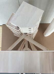
PHYSICAL MODEL

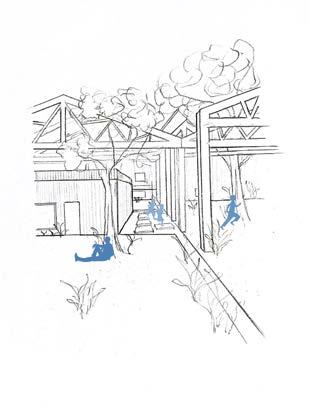
HANDRAWN PERSPECTIVE MOMENT SKETCHES WITH OCCUPATION PHOTOSHOPPED


HARDLINE DRAWING

EARLY SITE PLAN DESIGN SKETCH


WATER THRESHOLDS COURTYARDS AND CIRCULATION ZONES AND USES
HAND DRAWN SKETCHES AND OVERLAYS
CIRCULATION OVERLAY
FINAL MODEL/ AERIAL VIEW
PHYSICAL MODEL

FINAL MODEL/ THRESHOLD

STEPPING SONE POND
COURTYARD AND POND/ THRESHOLD
TERRACE WALKWAY AND POND/ THRESHOLD

FINAL DESIGN/ PLAN
HANDRAWN PERSPECTIVE MOMENT SKETCHES WITH OCCUPATION PHOTOSHOPPED
HARDLINE DRAWING
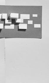
INITIAL CONCEPT MODEL
MODEL PHOTOGRAPHING
MODEL MAKING/ DESIGN PROCESS


WORK PROCESS
INITIAL CONCEPT MODEL
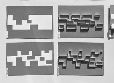
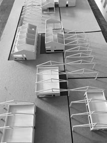
CIRCULATION MODEL
CIRCULATION AND COURTYARDS STUDY


SKETCH DESIGN WORK
SERIES OF SPATIAL STUDY


YEAR: 4th yr/ 2021
LOCATION: Tullow
In this project I designed a front to front terraced housing typology to complete an unfinished/ ghost estate in Tullow. The housing is orientated almost due south. Each house has access to a communal garden street which is rich with greenery and shared allotments from the front door of the dwellings and access to the bike and car street from the back door of the homes.

There are two unit types, ensuring this front to front design can be applied across the site and maximize natural light. The open plan living spaces are on the first floor maximizing use of natural light. The bedrooms and storage/ garage are on the ground floor in the darker spaces. There is a mix of public and private spaces including pocket parks and playgrounds which break up the terrace rows. Each dwelling has its own south facing courtyard on the ground floor and terraced roof garden on the first floor.
The site plan is designed to encourage interaction across the site through shared spaces and an addition of new access routes directly into the neighbouring estates.

• Aim: To densify and complete an incomplete ghost housing estatein Tullow


• Site area: 3.77ha
• Densify: 20DPH
• 2/3 bed housing
• Flexible homes for future growth
• Total units: 77
• Max residents: 462
• Demographic: families


SITE HOUSING UNIT DESIGN SKETCHES FORM/ STREET MODEL
FIRST FLOOR PLAN

SOUTH ELEVATION
EAST/ WEST ELEVATION GROUND FLOOR PLAN
HOUSING UNIT GA DRAWINGS

DESIGN STUDY SKETCHES FINAL DRAWINGS CONCEPT MODEL

ELEVATIONS INTERNAL VIEW INTERNAL


SITE ELEVATIONS


YEAR: 3rd yr/ 2020
LOCATION: Kilmainham, Dublin
I designed this primary care centre on the banks of the river Camac in Kilmainham. The southfacing building makes the most of the sunlight through tall glazing and a stretched long plan. I designed the health center in a way which connects people to the surrounding nature, Each room has generous windows and privacy in controlled through the use of clever paths and single sided spaces. Each patient room has a balcony and views out over the river Camac on the south end of the site.
The building is broken up into a mix of public, semi public and private areas. The two blocks are connected by a winter garden which enables patients to stretch their legs and get some cool fresh air all year round with the sound of the small tributary of the river directed through the space. Forest paths wind around the site giving the community and patients access through the site.
The form takes inspiration from Paimio Sanatorium with long, bright patient wings. I was inspired by the trees on the site to make use of a grid system which made the trees a part of the architecture. This can be seen in my sketches and model photographs.


YEAR: 2nd yr/ 2019
LOCATION: Sandycove, Dublin
The Bath house is designed to make sea swimming accessible all year round for the local coastal community in Sandycove. My design incorporates a variety of salt water pools varying in depths and sizes. Some are open to the waves and others closed. There is also a 20m lengths pool and a seaweed treatment bath and two indoor baths including a caldarium and frigidarium.
This Bath house is designed for all ages. The pools are easily accessible for the elderly and are also a safe place for children to play in the shallows or non-tidal pools whilst parents go for a swim nearby. The internal building houses the caldarium, changing rooms, showers, toilets and a beautiful cafe inspired by Siza’s Boa Nova Tea house. The cafe sits down in the rock with views out across the pools over Dublin bay.
The form of the design follows a series of bold irregular angles which stem from an admiration for the natural rockpools I observed whilst visiting the site. The baths are still exposed to the elements but the wave action is reduced to different degrees in the various pools, making swimming more pleasant. Once a person has done their sea swim they may retreat into the warmth of the public changing rooms and warm up in the cafe looking out to sea with a cup of coffee or if in a rush they can use the outdoor showers on their way home.


SITE PLAN DESIGN CONCEPT SKETCH

SITE PLAN DESIGN SKETCH


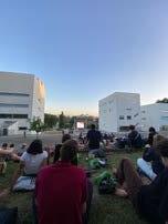


In Porto Academy I worked alongside DFDC Architects on an exploration study of voids. My group and I were interested in the deep feeling one gets once immersed in these spaces as well as the bold form and light. We modelled this feeling as spheres and took photographs and videos though the space we created to capture what we see a void as.