History of Computer Drafting
In 1950 Dr. Paul Hanratty developed a Computer Aided Drafting (CAD) program that let users create simple line drawings. In 1957 researchers at MIT developed Pronto, a program that enabled more complicated drawings. However, computers were physically enormous and very costly, so these programs were not widely adopted. During the next 20 years more Computer Aided Drafting and Design (CADD) programs were developed but limited to large manufacturing companies for their own use.
In 1982 the Autodesk Company introduced its AutoCAD architectural drafting program (Figure 1.4). This program replicated the manual drawing process where drafters used the mouse like a pencil to create 2D drawings. For the next decade AutoCAD was primarily used by large companies as it, and the computers needed to run it, were too expensive for small businesses and personal users. But in the1990s both software and hardware prices dropped and computers became smaller and cheaper, which resulted in AutoCAD becoming the dominant drafting program for personal users and companies of all sizes.
CADD evolved to modeling programs. This is software in which everything is drawn in 3D; the drawing is called a model, and 2D views are generated from it (Figure 1.5).
Some modeling software has Building Information Modeling/Management (BIM) capabilities. With BIM software, the model is hosted on a server and everyone in the project works collaboratively on it. A BIM model contains more than just construction information; it also has document management, coordination, simulation and life cycle operation and maintenance information. Currently, the dominant architectural BIM program is Revit
Figure 1.4
AutoCAD uses the mouse like a pencil to create 2D pictures.
Professional Groups and Certifications
Architectural drafting is done by those who work in the interior design and architecture fields. Professional groups and certifications include:
• American Society for Interior Designers (ASID). This national organization represents interior designers and interior design students. It advocates for the profession, provides continuing education and advice on running a practice, and hosts awards and competitions.
• National Council for Interior Design Qualification (NCIDQ). This nonprofit organization oversees the eligibility, examination, and certification of interior designers.
• American Institute of Architects (AIA). This national organization represents licensed architects and architectural interns. Its activities include influencing legislation for professional liability, licensing requirements, building codes, preservation, and environmental concerns. The AIA also provides professional development opportunities and hosts a yearly convention. There is an AIA for each state.
• National Council of Architectural Registration Boards (NCARB). This organization recommends model laws, regulations, and other guidelines. NCARB also develops, administers, and maintains the Architect Experience Program (AXP) and the Architect Registration Examination (ARE). Each state also has its own registration requirements for licensing architects.
Figure 1.5
A SketchUp model of a house and 2D views generated from it.
• Council for Interior Design Accreditation (CIDA). This organization accredits interior design programs to assure the public that an education in any program prepares students to be responsible, well-informed, skilled professionals.
• Council for Interior Design Qualification (CIDQ). This is the certifying body that develops and administers the NCIDQ.
• International Interior Design Association (IIDA). This global organization supports commercial interior designers, industry affiliates, educators, students, companies, and their clients.
• National Kitchen and Bath Association (NKBA). This national organization provides education and support to the kitchen and bath industry. Professional certifications that can be obtained through it include Associate Kitchen & Bath Designer (AKBD), Certified Kitchen Designer (CKD), Certified Bath Designer (CBD), and Certified Master Kitchen & Bath Designer (CMKBD). It has many local chapters.
• US Green Building Council (USGBC). This organization provides a framework for identifying and implementing sustainable building design, construction, operations, and maintenance. Its internationally recognized green building certifications include Leadership in Energy and Environmental Design (LEED) and Regreen
There are currently over 90 building certifications in the United States. The three largest are LEED, National Association of Home Builders (NAHB), and EnergyStar.
Exercise
Visit the USGBC website and write short descriptions about each LEED rating system found there.
Design Thinking This is the process of creative problem solving. It’s utilized in every field, not just the obviously creative ones; technology and manufacturing benefits from design thinking, too. An interior design project calls for problem-solving skills at every stage of the process—from thinking what it will look like, to drafting it, to fixing unexpected issues during construction. Design thinking requires thoroughly understanding the needs and wants of the client, being agile and adaptive, brainstorming ideas fast and prolifically, being a critical thinker, and being bold, innovative, and creative.
Design thinking is iterative and non-linear. Intuition, empathy, and pattern recognition must be employed to create meaningful, functional solutions. Developing prototypes, which are preliminary models of the solution that test both the design and user reaction to it, are done during this thinking process. Prototypes can be anything from a sketch to a pop-up space (short-term, temporary retail store) to a 3D print (physical object made from a digital model) (Figure 1.6).
Figure 1.6 3D print of a house.
The Design Process Design thinking is interwoven with the design process. The AIA, ASID, and NKBA list five stages in this process: programming, schematic design, design development, construction documentation, and contract administration. Drafted drawings and other visuals are used at all of them. Following are descriptions of those stages, the activities done in them, and the documents produced.
Programming This is the research stage. Information that will affect the design must be gathered, analyzed, and synthesized. Such information includes spaces required; their functions and square footage; how many people will use them and how; which spaces should be adjacent, separated, public, private, or secured; the traffic flow of goods, services, and people; and the furnishings and equipment needed. Regional limitations, context, cost, energy usage, accessibility, and aesthetic and functional requirements (mechanical, electrical, and plumbing systems) are evaluated. Life cycle cost, organizational and image goals, and environmental concerns may also be considered. Some projects go through the site selection process at this stage.
Other issues include physical conditions that affect occupant health and safety (air quality and circulation, temperature control, ergonomic layout, and the physical circulation plan); maintenance concerns (ability of the products and materials to be kept in good condition, as well as the work required to keep that condition over the material’s life span); and sustainability (using resources in a manner that does not deplete them and will have the least long-term effect on the environment).
An architectural program, also called a project statement, is written. This is a description of client needs and wants. It describes the problem, scope, goals, requirements, and constraints (Figure 1.7).
Depending on complexity, a program can be one or one hundred pages long. Adjacency matrixes (Figure 1.8) and criteria matrixes may also be drawn, which show space relationships and requirements in a visual manner.
The occupancy and occupant load are also determined. Occupancy is a category that describes the building’s use, and occupant load is the number of people the building is expected to hold. There are ten occupancy categories: assembly, business, educational, factory, high-hazard, institutional, mercantile, residential, storage, and utility/misc. There is also mixed occupancy, meaning more than one type of occupant.
Schematic Design In this phase ideas are developed. Concept and parti sketches are drawn. Concept sketches sum up the “big idea,” that is, the design’s main function or appearance (Figure 1.9).
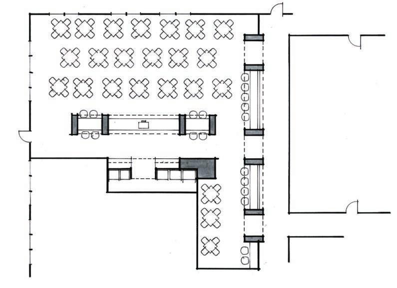
Parti sketches show the organizing thoughts of a design and the relationship of parts to the whole. For instance, in Figure 1.10 we see the beginnings of a hospital design. The sketch shows the main areas, their spatial relationships, and where/how the user starts experiencing it all.
Bubble Diagrams A bubble diagram is a concept sketch that organizes and articulates ideas and helps the designer visualize how everything will work together. It contains labeled circles that represent spaces and functions occurring inside. Different size circles reflect different space needs. Rooms, orientations, traffic patterns, views, and physical and visual access are shown, along with arrows that describe traffic patterns. Other design considerations, such as landscaping, direction of breezes, sun, and buffer zones or sound, may also be shown.
Program for a Custom-Built Vacation Home
Goal: Design a family vacation home in Rio Rancho, NM.
Client Description: The Eve family owns a corner lot with a mountain view in a town outside Albuquerque. They want a ranch style home that maximizes the views, has a Southwest style, and accommodates their family of two adults and two minor children. Short term renters will also use the house.
Required Rooms:
1. Kitchen that accommodates gourmet cooking and family/friend gatherings
2. Walk-in pantry
3. Family room that accommodates the Eves plus up to eight guests.
4. Exercise room that accommodates fi ve machines and storage for weights
5. Theater with a large screen that accommodates 8 viewer s.
6. Game room that accommodates 5 vintage gaming machines
7 Laundry room with sink and space for ironing
8. Master bedroom with pri vate sitting area and office
9. 2 children’s bedrooms with shared bathroom
10. 1 guest bedroom with bathroom
11. Outside li ving spaces with outdoor kitchen
12. Two-car garage
Required Adjacencies:
1 Kitchen must have physical access to family room and convenient access to a large, walk-in pantry.
2. All pri vate spaces must have direct access to pri vate bathrooms.
3. Public spaces must have convenient access to outside li ving spaces and views.
4. Master bedroom and office must have direct access to outdoor space.
5. All bedrooms must have direct access to large closets.
6. Garage must be directly attached to house.
Other:
Exterior finish material to be stucco. House should be adobe style with exposed beams, tile flooring and wrought iron gates. Natural light and breezes should be incorporated. House should project an upscale Southwest look. Security, intercom, wireless Internet and streaming must be incorporated in all rooms. Front and back lawn to be rock and indigenous plants for easy maintenance.
Figure 1.7
A program is a written description of client needs and wants.
ADJACENCy MATRIX FOR THE EVE FAMILy VACATION HOME KITCHEN
KITCHEN FAMILy ROOM
EXERCISE ROOM
THEATER GAME ROOM
LAUNDRy ROOM
MASTER BEDROOM
CHILDREN’S BEDROOMS
GUEST BEDROOM DIRECTLy
Figure 1.8 Adjacency Matrix for the program in Figure 1.6.
Tip Habitable spaces are those that building codes consider capable of being fit to live in. Other words for habitable spaces are occupiable, dwelling, sleeping, and living.
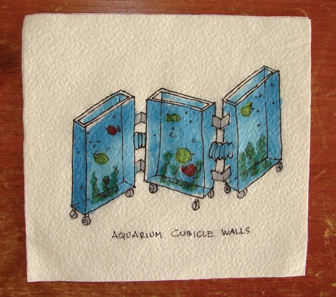
Figure 1.9 A concept sketch for office cubicle walls.
1.10
Parti sketch for a hospital layout.
Courtesy of mkerrdesign. com
As the bubble diagram evolves from rough to refined, it becomes a block diagram, a graphic that resembles a floor plan. Once scale is introduced, the block diagram transitions to floor plan, a scaled diagram of room arrangement. Figures 1.11 through 1.16, done by Jay Colestock, AIA, of Colestock and Muir (www. cmarchitects.com), show the diagram development of a floor plan from bubble to refined block.
Figure 1.11
Start the architectural design process with property characteristics.
Figure
Figure 1.12
Diagramming the bedroom and family areas.
Figure 1.13
Diagramming the formal spaces and master suite.
Figure 1.14
Pulling all the bubble diagrams together.
Figure 1.15
Refining the bubble diagram into a block diagram.
1.16
The design layout.
Mood Boards Mood boards, which are visuals that describe the design essence without being specific, may also be presented (Figure 1.17). A mood board’s goal is to evoke emotion and convey the design direction in an unspecific way. Any photos, symbols, materials, and textiles that capture the designer’s thoughts for how the space will affect the user or hint at its appearance can be used. A mood board is not the same as a color board, which shows the actual materials selected.
Figure
Figure 1.17
Mood board for a vacation home in the Southwest.
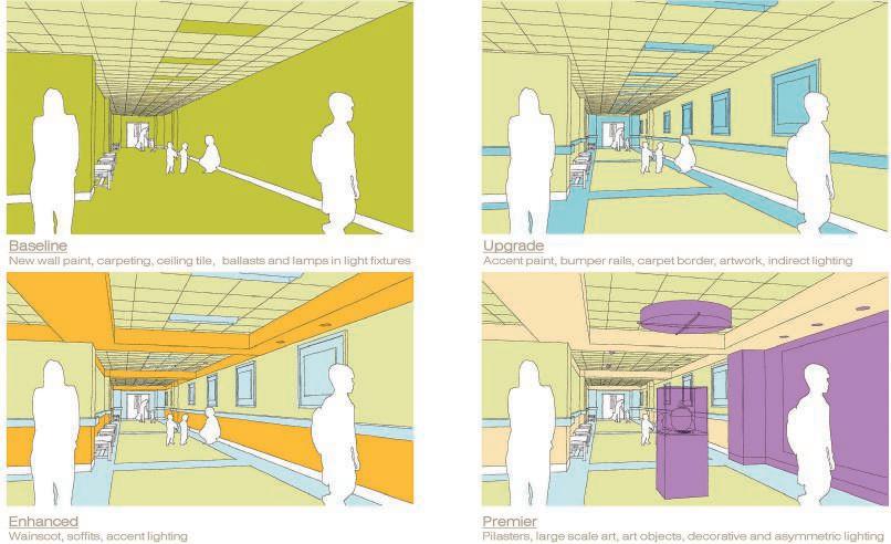
Design Development The project now goes from concept to workable design. Visuals may include color sketches (Figure 1.18), scale models (Figure 1.19), color boards (Figure 1.20), or anything else that communicates the idea. The visuals selected should address the specific audience. For instance, the floor plan shown in Figure 1.21 may be appropriate for a client presentation, but not for a builder.
Two-point interior perspective sketch created with SketchUp and hand-colored with marker. Courtesy of mkerrdesign.com.
model of a custom-designed residence. Paper elevations are glued to foam core board. Courtesy of wolfgangtrost.com.
Figure 1.18
Figure 1.19
Scale
Figure 1.20
Color board for an office building lobby. Courtesy of Matthew Kerr, mkerrdesign.com.
Figure 1.21 Presentation sketch. Courtesy of mkerrdesign.com.
Exercise
Obtain some presentation drawings. Find three ways their graphics differ from similar graphics on production drawings.
Local codes, ordinances, and zoning, which are regulations for aesthetics, traffic, and activities inside a building are researched, as are building codes, and a detailed code review is done. Building codes are rules that govern design and construction and address risk factors that characterize the people and activities in the space. For instance, a nightclub has dim light and loud music; offices have upholstered furniture, paper, and other flammables; nursing homes have occupants with limited mobility; prisons have occupants with restricted mobility; and theaters have many occupants in one space. Codes help ensure that all types of buildings provide their users with an appropriate level of safety to live and work. Room size, number of exits, lighting, hallway length, and interior finish selection are just a few examples of code-dictated features.
The International Code Council (ICC) (Figure 1.22) is a standards organization that writes 15 separate model codes. These are building codes written by a standards organization independent of the governing authority (e.g., state government, fire district, or municipality) that adopts and enforces them. Model codes do not become law until a governing authority adopts them. The two ICC codes most applicable to interior designers are the International Residential Code (IRC), which applies to one- and two-family homes of three stories or less, and the International Building Code (IBC), which applies to commercial construction. Other relevant codes are the Life Safety Code (LSC) and National Electric Code (NEC), written by the National Fire Protection Association (NFPA), which is another codes standards organization. The LSC covers hazards to human life in buildings and the NEC covers the safe installation of electrical wiring and equipment. The Americans with Disability Act (ADA) is a civil rights law that prevents discrimination to the disabled, and applies to public and commercial buildings; ANSI-A117.1 is the Accessible & Usable Buildings & Facilities code; and the Occupational Safety and Health Administration (OSHA) writes workplace safety and health codes.
Figure 1.22
The International Codes Council (iccsafe.org) writes model codes for the design and construction industries.
Figure 1.23
Set of construction drawings for apartment villas.
Construction Documentation The design is finalized in this stage, and documents that serve as legal and binding instructions for building are drafted (Figure 1.23). These instructions include architectural, structural, electrical, mechanical, plumbing, and any specialty drawings.
Specifications are written descriptions of quality of materials and workmanship standards. For instance, the drawings show where carpet is to be laid; the specifications discuss the carpet’s material, pile height, backing, and glue. Schedules, which are charts of information, are done for the fixtures, furniture, and equipment to be purchased. Producing a complete set of construction documents is a team effort to which many professionals contribute.
Exercise
Obtain some production drawings and their accompanying specifications. Find three materials and compare/contrast how they are described in the drawings and how they’re described in the specifications.
Contract Administration In this phase the job is awarded to a contractor (assuming the contractor wasn’t selected at the outset; in such cases the contractor may even provide the drawings). Time schedules, which describe workflow, are created by construction managers. Shop drawings are also created at this phase. These are highly detailed production drawings of items shown in the design drawings and are created by contractors, subcontractors, manufacturers, or fabricators. For example, where the design drawing might show a simple drawing of a steel beam, the shop drawing shows how many bolt holes it has, the exact size of its flanges, and pictures of the bolts themselves. They are a communication from the fabricator to the designer that says, “As I understand it, this is what you want, and this is how I plan to produce it.”
Summary
Drafting is graphic communication and is used to explain ideas and create instructions. It has a recorded history that spans thousands of years. Standardized ways of presenting those ideas and instructions have evolved to make drawings readable wherever they are created or read. Professionals who draft include interior designers and architects and various industry groups. Certifications are available to advocate quality and standards. Organizations also exist to regulate design and construction quality in the form of building codes. The design process requires design thinking and visuals for different stages of the documentation process. Different graphics and visuals are used, with all having the same purpose of communicating intent.
Classroom Activities
1. Draw a bubble diagram for a residence.
2. Create a mood board for a residential kitchen or small retailer.
3. Create an adjacency matrix for the part of the building your classroom is in.
4. Visit the ICC website and list the model codes it writes.
5. Visit your local city website and research what codes it has adopted.
6. Obtain a copy of the International Residential Code for One- and Two-Family Dwellings and research some specific topics, such as exit requirements or hallway lengths.
Questions
1. What is drafting?
2. Why is drafting used?
3. What does “LEED” mean?
4. What are the five stages of design, as recognized by the ASID, AIA, and NKBA?
5. What is an architectural program?
6. Why are building codes used?
7. What is a model code?
8. What is an adjacency matrix?
9. What is a bubble diagram?
10. What is a mood board?
Further Resources
American Institute of Architects (AIA). www.aia.org
American Society for Interior Designers (ASID). www.asid.org
Council for Interior Design Accreditation (CIDA). www.accredit-id.org
Free online access to an abbreviated version of ICC codes. https://codes.iccsafe.org/content/IRC2018
International Code Council (ICC). www.iccsafe.org
National Council for Interior Design Qualification (NCIDQ). www.ncidq.org
National Kitchen and Bath Association (NKBA). www.nkba.org
U.S. Green Building Council (USGBC). www.usgbc.org/LEED
Keywords
• 3D print
• adjacency matrix
• American Institute of Architects (AIA)
• American Society for Interior Designers (ASID)
• Americans with Disability Act
• ANSI-A117.1
• Architect Registration Examination (ARE)
• architectural program
• Associate Kitchen and Bath Designer (AKBD)
• AutoCAD
• Architecture Experience Program (AXP)
• block diagram
• bubble diagram
• building code
• Building Information Modeling/Management (BIM)
• Certified Master Kitchen and Bath Designer (CMKBD)
• Certified Kitchen Designer (CKD)
• Certified Bath Designer (CBD)
• color board
• Computer Aided Drafting (CAD)
• Computer Aided Drafting and Design (CADD)
• concept sketch
• construction documentation
• contract administration
• Council for Interior Design Accreditation (CIDA)
• Council for Interior Design Qualification (CIDQ)
• criteria matrix
• design development
• design thinking
• drafting
• dwelling
• EnergyStar
• floor plan
• graphic communication
• habitable
• International Building Code (IBC)
• International Code Council (ICC)
• International Interior Design Association (IIDA)
• International Residential Code (IRC)
• Leadership in Energy and Environmental Design (LEED)
• Life Safety Code (LSC)
• mixed occupancy
• model
• model code
• modeling programs
• mood board
• National Association of Home Builders (NAHB)
• National Council for Interior Design Qualification (NCIDQ)
• National Council of Architectural Registration Boards (NCARB)
• National Electric Code (NEC)
• National Fire Protection Association (NFPA)
• National Kitchen and Bath Association (NKBA)
• occupancy
• occupant load
• Occupational Safety and Health Administration (OSHA)
• ordinance
• parti sketch
• pop-up space
• programming
• project statement
• Pronto
• prototype
• Regreen
• schedule
• schematic design
• shop drawings
• specifications
• time schedules
• US Green Building Council (USGBC)
• visual communication
• zoning