ALEMLUBE ILC-MAX PUMP OPERATION
The DC gearmotor (1) provides continuous drive to the eccentric cam ( 2 ).

The pumping elements ( 3 ) are a push/pull design without return springs.
This cam also has a catch ring ( 4 ) so that as the gearmotor rotates, the pump element piston produces a suction stroke as it extends and a pressure stroke as it returns.
The body of the pump element contains a check valve ( 5 ) to ensure that lubricant cannot return to the reservoir.

The outlet body of the pump element has a relief valve ( 6 ) pre-set to 280Bar to protect components down stream from excessive pressure.
ALEMLUBE ILC-MAX STANDARD ONBOARD CONTROLLER 40.CCT.DC.05
TECHNICAL FEATURES
Operating Voltage 9-30vdc

Operating Temperature -20 to 80c
Digital Display LED
Input Type Sealed Push Button
OPERATING MODE OPTIONS
• Pause by Time, Run by Time (default)
• Pause by Counts, Run by Time
• Pause by Time, Run by Counts (e.g. Divider Cycles)
• Low Level Alarm
• High Pressure Alarm
DEFAULT SETTINGS
Pause Time – 2min, Run Time – 30sec.
There are three indicator lamps above the display: Green – Pause Time Yellow – Pump On Red – Alarm

In normal working mode, the digital display turns off after a few seconds. To turn the display back on, press the manual run button beside the power cable.
CONTROLLER SET UP AND ADJUSTMENT
Before any adjustment, the protective cover must be removed. There are 6 screws. Ensure the protective cover is replaced immediately after adjustments are completed.
NOTE: A manual run push button is located next to the power cable on the side of the pump
7 6
1 2 3 4 5 6
ALEMLUBE ILC-MAX BASIC SETTINGS & ADJUSTMENTS
ALEMLUBE ILC-MAX BASIC SETTINGS & ADJUSTMENTS
ENTERING REDUCED MENU PROGRAMMING MODE
Setting Reduced Menu
SCROLL DOWN SCROLL UP ENTER MENU
ENTER PROGRAMMING MODE
To exit running mode and enter programming mode, hold the ENTER button for 3 seconds. The green Pause and yellow Pump On lamps will flash together when in programming mode.

E-CM Programming mode is displayed
To select the required operating function, press MENU to enter the Operating Function menu
E-FU Enter operating function mode
To select different functions, use the up and down buttons to scroll through the different options.
FU.PL Pause by time, lube by time*
FU.IL Pause by pulses, lube by time
FU.PC Pause by time, lube by counts
FUNCTION MENUS
Once the required Operating function is selected, press MENU for the enter function menu
E-FU Enter Function Menu
Then using the scroll keys, the different menus can be selected and the values entered
E-PM Pause Time in Minutes*
E-PH Pause Time in Hours*
E-LS Lubrication Time in Seconds*
E-LM Lubrication Time in Minutes*
E-CS Lubrication by Divider Cycles in three ranges, 1-16, 17-32, 33-48
E-CT Divider Cycle Monitor Time (seconds)
ENTERING VALUES
When the required menu is selected, e.g. E-PM (Pause Time in Minutes), press the MENU button to enter value selection - Scroll up/down to increase/decrease the value. Press MENU to confirm and exit the value selection and return to enter function menu. Scroll to the next mode required e.g. E-LM (Lubrication Time in Minutes) and press MENU to enter value selection for the pump running time.
EXITING PROGRAMMING MODE
Once the required values have been entered and confirmed ( MENU button), then scroll up the Function Menu until E-CM is again displayed.
Press ENTER for at least 5 seconds to exit Programming mode. The pump is now programmed and begins the lubrication cycle.
*Default settings
Hold the key down for 3 seconds to start programming
The letters E-CM appear with the 2 LEDs flashing on the left Press the button
Scroll to CM-b using Press E-CM appears E-CM is now in Basic Menu Mode
NOTE: CONTROLLER DEFAULT SETTINGS
New pumps are factory preset to the minimum settings –PAUSE E-PM = 2 minutes

LUBE E-LS = 30 seconds
NOTE: TO ADJUST TO NEW SETTINGS –e.g PAUSE E-PH = 1 hour, LUBE E-LM = 3 minutes, Ignore the default settings and enter the new E-PH and E-LM settings in hours and minutes


Then zero out the old default E-PM and E-LS minutes and seconds settings.

9 8
ALEMLUBE ILC-MAX BASIC SETTINGS FU.PL – PAUSE BY TIME, RUN BY TIME
Pause time in H/M/S (FU-PL) Working time in M/S
From E-CM press until E-FU appears
Press
Select FU.PL using Press to confirm and return to E-FU
ALEMLUBE ILC-MAX ADVANCED SETTINGS & ADJUSTMENTS
Enter Complete Menu Programming Mode to access all the controller function menu including Low Level Alarm, High Pressure Alarm and Control by Cycles.
Hold the key down for 3 seconds to start programming
The letters E-CM appear with the 2 LEDs flashing on the left Press the button
From E-FU press
Select CM-b using Press
E-PM appears
Press
Set a pause time from 2 to 999 minutes using Press to confirm
Press E-PH appears Press
Set a pause time from 2 to 999 hours using Press to confirm
Press E-LS appears Press
Set operating time from 3 to 999 seconds using Press to confirm
Press E-LM appears
Press
Set a working time from 0 to 999 minutes using Press to confirm
Select E-CM using
If the set-up is completre press for 5 seconds
E-CM appears
E-CM is now in Complete Menu Mode
CM-F Full (Complete) Menu Programming Mode
Press MENU returns to Complete Menu Mode E-CM
Scroll up/down now gives the following new options
E-AL Low Level Alarm Enabling
E-AP High Pressure Alarm Enabling
E-AC Cycle Alarm Enablingw


11 10
ALEMLUBE ILC-MAX ADVANCED SETTINGS & ADJUSTMENTS
LOW LEVEL ENABLE/DISABLE
Start from E-CM (Complete Menu Mode)
Select E-AL using Press Select using AL-0 alarm not enabled AL-1 alarm enabled Press to confirm


In the event of an alarm, the display will show 1.1AL. This alarm does not block the pump if triggered
ALEMLUBE ILC-MAX ADVANCED SETTINGS & ADJUSTMENTS
HIGH PRESSURE ENABLE/DISABLE
Start from E-CM (Complete Menu Mode)
Select E-AP using Press Select using AP-0 off AP-1 on Press to confirm
In the event of an alarm, the display will show 1.1AL. This alarm does not block the pump if triggered


13
ALEMLUBE ILC-MAX ADVANCED SETTINGS & ADJUSTMENTS
ENABLE/DISABLE CYCLE ALARM
Required in FU.PC mode to pause by time and run (and monitor) by divider cycles
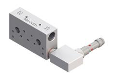
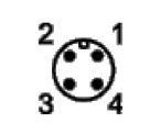
ALEMLUBE ILC-MAX WIRING

MANUAL RUN PUSH BUTTON
Start from E-CM (Complete Menu Mode)
Select E-AC using Press Select using AC-0 cycle alarm not enabled AC-1 cycle alarm enabled Press to confirm

In the event of an alarm, the display will show bloc. This alarm blocks the pump if triggered

Isolate unless button fitted
MAIN POWER SOCKET
5m power cable assy 40CBL510AK
10m power cable assy
40.CBL.5.10.AK
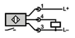
M12x1 CABLE SOCKET

Connect to –
High Pressure Switch 097127 And enable E-AP in controller

Isolate unless lights fitted
ALTERNATIVELY – FOR FULL VOLUME CONTROL MONITORING
Connect to –
Master divider proximity switch
And enable FU.PC mode And enable E-AC in controller
15 14
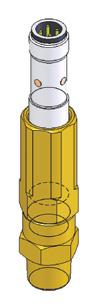
ALEMLUBE ILC-MAX PUMP ELEMENTS

Two types of pump elements are available
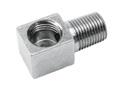
90.900.0 FIXED VOLUME
0.160cc/revolution
Includes banjo relief valve assy A70095133 OUTLET – ¼”BSP
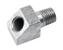
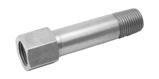
90.900.3 ADJUSTABLE VOLUME
Volume adjustable from
0.01cc/revolution to 0.16cc/revolution
Includes relief valve A68075011 OUTLET – ¼”BSP


ALEMLUBE ILC-MAX PUMP ELEMENT INSTALLATION
Only install pump elements when the pump power cable is unplugged.
• First Remove the covering plug from the pump element port
• Clear grease from inside the pump – use a finger to push the grease away and feel where the eccentric and the catch ring are located inside
• Extend the pump element piston to 30mm
• Insert the piston and pump element into the housing on an upward angle so that the piston head touches the eccentric
• Move the pump element into a horizontal position
• The piston head must run in the groove between the eccentric and the catch ring
• Engage the thread and tighten the pump element just a few turns
• Plug the power cable back in and start the pump
• Slowly tighten the pump element until tight, ensuring that the pump is rotating smoothly and grease is beginning to be discharged
• Torque the pump element to 25-30 Newton Metres maximum
• For removal, reverse the above procedure ensuring that the piston is not left behind inside the pump housing
ADJUSTMENT PROCEDURE
The delivery rate of the pumping element can be adjusted by loosening the locking nut (c) and rotating the adjustment screw (b) clockwise to reduce delivery, or counter clockwise to increase delivery. The output adjustment table shows the outputs that can be obtained by varying the distance (A) of the adjustment screw.

IMPORTANT: DO NOT ADJUST DISTANCE “A” LONGER THAN 23.6mm

17 16
DISCHARGE ADJUSTMENT TABLE A Discharge / Cycle Percentage 23.6mm 0.16cc 100% 22.5mm 0.12cc 75% 21mm 0.08cc 50% 19.5mm 0.04cc 25% 18.5mm 0.01cc 6%
SETTINGS FLOW CHART

19 18
ALEMLUBE MINI-MAX PUMP STATION
ELECTRIC PUMPS – GREASE (MINI-MAX) APPLICATIONS

Ideally suitable for the automatic grease lubrication of small machines in transport, construction, agriculture and industrial applications. In conjunction with DPX progressive dividers, multiple points can be automatically centralized from just a single grease pump.
OPERATION
The pumps are designed for intermittent or continuous operation to provide regular pre-programmed lubrication cycles as required for the application.
A direct-mounted electric geared motor drives an internal rotating cam, which can actuate up to two large volume externally mounted pump elements and 8 mini pump elements. The large elements have a relief valve to protect the system against over-pressure and give indication of a blockage downstream – these are designed to supply the DPX progressive dividers.


The mini pump elements have no pressure relief and are designed to supply direct from pump element to bearing.
PUMP DESCRIPTION
The transparent reservoir has 1 KG capacity. The pumps can attain a maximum recommended operating pressure of 200 bar per outlet and delivery of up to 2.4cc/minute for a large pump element.


The internal drive shaft is coupled to a specially formed stirring paddle in the reservoir of the pump unit which ensures continuous priming of the pump element inlets, even with grease up to NLGI No. 2 consistency at ambient temperature down to -20 °C The gear motor is protected by mean of an IP-6K9K.
The pumps have an integrated electronic control timer built in. The timer can be programmed to automatically operate the pump with variable “working time” and “pause times”.
21 20
ALEMLUBE MINI-MAX PUMP GENERAL SPECIFICATIONS
ALEMLUBE MINI-MAX PUMP OPERATION

SETTING DIP SWITCH FUNCTIONS


The DC motor (11) provides continuous drive to the eccentric cam (2). The pumping elements (7 and 6) are a spring return design so that as the eccentric cam rotates, the pump element piston produces a suction stroke as the spring extends it and a pressure stroke as the cam pushes it in. The body of the pump element contains a check valve to ensure that lubricant cannot return to the reservoir. The outlet body of the large pump elements have a relief valve pre-set to 200Bar to protect components down stream from excessive pressure.
ALEMLUBE MINI-MAX TIMER SETTINGS

The MINI-MAX has an integrated timer behind a transparent window with a manual button/ indicator light display, two rotary adjustments and a row of 6 dip switch function settings.

MANUAL BUTTON, INDICATOR LEDS, S3 & S4 ROTARY ADJUSTERS
23 22
SETTING STAND-BY TIME
ALEMLUBE MINI-MAX WIRING
10m power cable assy 40.CBL.5.10.AK
MAIN POWER SOCKET
5m power cable assy 40CBL510AK
10m power cable assy
40.CBL.5.10.AK
SETTING THE WORKING TIME


Isolate unless button fitted
The pump can work in divider cycle control mode by selecting dip switch #4
ALTERNATIVELY – FOR FULL VOLUME CONTROL MONITORING Connect to –
Master divider proximity switch And enable FU.PC mode And enable E-AC in controller
Isolate unless lights fitted
25 24
ALEMLUBE MINI-MAX PUMP ELEMENTS


ADJUSTABLE PUMP ELEMENT ADJUSTMENT


27 26
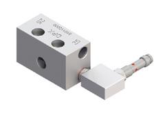
ALEMLUBE DPX PROGRESSIVE DIVIDERS
FEATURES AND DESCRIPTION
• The DPX progressive divider system doses lubricant with a progressive piston movement. Every piston controls the following one in sequence through a single delivery flow.
• This system is perfectly designed for delivering oil and grease to one or more journals or bearings. Each piston is in series with every other piston, so that every piston must move through its stroke to allow the next to move.
• If a piston is unable to move due to high back pressure from a blocked bearing, a blocked outlet or a malfunction, the sequence is broken and the lubricant flow through the entire divider stops.
• This stoppage can also occur if the lubricant is too stiff or too cold, or is broken lines are blocked off.
• When a stoppage occurs, the pump continues to build pressure, up to the relief valve setting of 280Bar. This high pressure may clear the obstruction.
• Due to this unique progressive design, the entire distribution system can be easily checked and monitored with a single visual indicator or a single electrical switch.
• The pump flowrate is divided when the divider valves are arranged in a cascade. A master divider can supply one or more secondary dividers.
• It is recommended to have no more than a two level cascade due to pressure drop and compressibility. Extending to a third cascade can cause irregular flow, especially in grease systems.
ALEMLUBE DPX PROGRESSIVE DIVIDERS
BENEFITS
• Positive discharge of measured quantity of lubricant guaranteed
• Suitable for fully automated lubrication
• Long operational life assured by a careful selection of high grade material and strict quality control
• Operation is fully monitorable with indicators and/or switches
• System design flexibility is excellent due to large range and combination of sizes
DATA SHEET
Discharge / Stroke for each outlet 25mm³ - 45mm³ - 75mm³ - 105mm³

Elements Number From 3 to 12
Operating Pressure From 15 to 300 Bar
Operating Temperature -20°C a + 100°C
Body Distributor Galvanized Steel Zi-Ni (free from Cr-V)

Number of Cycle / Minute Maximum 300/min
Inlet 1/8" BSP
Outlets M10 x 1
Mounting Screws M5 x 30
Lubricants Mineral Oil 46 cSt - Grease Maximum NLGI-2
Control Elements Visual and electric for signaling cycle and overpressure
Main Lines Pipelines Ø 8-6
Secondary Lines Pipelines Ø 6-4
29 28
ALEMLUBE DPX PROGRESSIVE DIVIDERS
FUNCTION
A
Lubricant flow pressure ( blue ) moves piston 1 to the left allowing lubricant discharge ( yellow ) from B.
ALEMLUBE DPX PROGRESSIVE DIVIDERS
FUNCTION
D
When piston 3 reaches its limit, lubricant flow pressure ( blue ) operates on piston 1. Lubricant volume ( yellow ) discharge from A.
E
When piston 1 reaches its limit, lubricant flow pressure ( blue ) operates on piston 2 . Lubricant volume ( yellow ) discharge from C. C


When piston 2 reaches its limit, lubricant flow pressure ( blue ) operates on piston 3. Lubricant volume ( yellow ) discharge from E .
When piston 1 reaches its limit, lubricant flow pressure ( blue ) operates on piston 2 . Lubricant volume ( yellow ) discharge from D.
F
When piston 2 reaches its limit, lubricant flow pressure ( blue ) operates on piston 3. Lubricant volume ( yellow ) discharge from F. The pistons have now all returned to their initial positions, ready to begin another cycle.
31 30
B
1 2 3 1 2 3 1 2 3 1 2 3 1 2 3 1 2 3
ALEMLUBE DPX PROGRESSIVE DIVIDERS OUTLETS
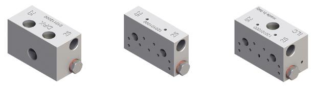
Double outlets
• Each divider piston is arranged in order to feed 1 or 2 outlets.
• When the separation grub screw and ball is inserted ( see Fig.1), the discharge is carried out in both sides.
• When the grub screw and ball is not inserted ( see Fig.2 ), the double discharge is carried out in one of the two available outlets.

• If it is necessary to use a single outlet, extract the ball (A92.089005), and the separation dowel (UNI5925-M4X6) and insert a plug (A73.087010 +A92.127006) in the unused outlet.

• The dividers are supplied with the separation grub screw and ball inserted and the two outlets open as standard.

Single outlet
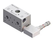
ALEMLUBE DPX PROGRESSIVE DIVIDERS
STANDARD
WITH M12 INDUCTIVE SENSOR
NOTE: INLETS AND ENDS - access the grub screw and ball from the left!
MIDDLE SECTIONS - access the grub screw and ball from the right!
IMPORTANT
It is not possible to shut both outlets of a piston. All the operations explained have to be made in a clean environment.
NOTE: Tie-Rod torque 10 Nm
33 32
DIMENSIONS
Outlets A (mm) H (mm) 6 64.4 46.7 8 79.1 61.4 10 93.8 76.1 12 108.5 90.8 14 123.2 105.5 16 137.9 120.2 18 152.6 134.9 20 167.3 149.6 22 182.0 164.3 24 196.7 179
Discharge Inlet valve section Valve middle section End valve section 25mm³ 2.A.025.D.1N.M10 2.B.025.D.1N 2.C.025.D.1N.M10 45mm³ 2.A.045.D.1N.M10 2.B.045.D.1N 2.C.045.D.1N.M10 75mm³ 2.A.075.D.1N.M10 2.B.075.D.1N 2.C.075.D.1N.M10 105mm³ 2.A.105.D.1N.M10 2.B.105.D.1N 2.C.105.D.1N.M10
Discharge Valve section End valve section 45mm³ 2.B.045.D.3I.M12 2.C.045.D.3I.M10.M12 75mm³ 2.B.075.D.3I.M12 2.C.075.D.3I.M10.M12 105mm³ 2.B.105.D.3I.M12 2.C.105.D.3I.M10.M12 Elements A (mm) Code 3 45 2.TR.03 4 60 2.TR.04 5 75 2.TR.05 6 90 2.TR.06 7 105 2.TR.07 8 120 2.TR.08 9 135 2.TR.09 10 150 2.TR.10 11 165 2.TR.11 12 180 2.TR.12
TIE-RODS
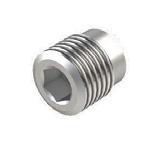
Grub Screw Ball
O Ring Outlet Plug
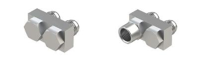
ALEMLUBE DPX PROGRESSIVE DIVIDERS
Inlet and outlet manual grease points
Banjo
Part No. Thread Divider
1001029 M10x1 DPX-N
ALEMLUBE DPX PROGRESSIVE DIVIDERS
Crossport bridges with and without outlet
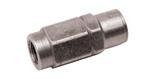
Outlet check valve for 6mm tube
Outlet
With Check Valve
6116803
Outlet fittings plain for 6mm tube
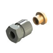
Part No.
04.052.0 6mm Tube nut M10x1
05.052.0 6mm Tube olive
Outlet plug & O-Ring
DPX-N Plug
Part No. Thread
A70.093229 M10x1
Inductive sensors
In this control a proximity switch is housed in a composite block.


The piston opens and closes the contact as it moves into its operational seat. They are usually used in cycle control systems where they can count up to 300 movement for minute.
Voltage 6-30 V DC
Outlet Current Max 200 mA
Current < 22 mA
Operating Temperature from - 25 °C to +70 °C
Protection IP 67
Sensor Housing Stainless steel
Sensor Block Pet-G
Connection M8x1 - M12x1
35 34
DPX-N Bridges Without Outlet With Outlet 09.600.3 09.600.4
ALEMLUBE REFILLING PUMPS
424170
Samoa 20kg Air Operated Grease Kit
• Delivery rates of up to 0.9kg/min
• 55:1 ratio air motor develops grease pressures of up to 7,950psi (548bar)
• Will handle high density, tacky greases up to NLGI2
• Supplied with a 4m long hose assembly enabling quicker and easier greasing of your plant and equipment
• Heavy duty 3 jaw coupler ensures a tight and precise grease nipple connection
• Cast alloy dual cylinder air motor won’t dent or distort prematurely
• Manufactured in Spain
453000
Samoa 180kg
Workshop Stationary Grease System
• Includes a 180kg grease pump and drum cover
• High pressure grease control gun with z-swivel
• Open type single arm with 15m x 3/8" hose
• 550mm follower plate
• 55:1 pressure ratio pump
ALEMLUBE PUMP FILLING ADAPTORS
7667
Alemlube 20kg Grease Filler Kit
• Ideal for grease transfer applications where compressed air is not available
• Includes a hand operated medium pressure, high volume grease transfer pump


• Suitable for use with 20kg drums
• Delivers up to 77cc of grease per stroke
• Develops up to 500psi (34 Bar) grease pressure
• Supplied inclusive of a drum cover, follower plate, quick connect high volume coupler and 2 metres of delivery hose
• Helps to protect your lube system and valuable plant & equipment against foreign particles contamination
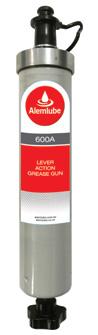
650A
Alemlube ALS Lube System Grease
Pump Reservoir Refiller
• Simple and effective filling from 450g cartridges
• More convenient than using a 20kg drum
• No pneumatic or manual bucket pump required
• Operator can keep the 650A and spare cartridges on board
• Low cost fast contamination free grease filling on site
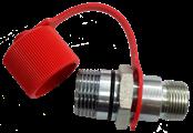
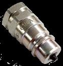
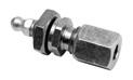
QDP-04
Dust Cover for R80-04M
R80-04M 1/4" BSP High Pressure Fill Coupler
TROUBLESHOOTING GUIDE
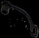
ZZZ 100-208 M22 Fill Coupler for 650A
Basically, the only maintenance required is to refill reservoir with clean suitable quality grease in good time using a pump. However, check regularly that lubricant is actually reaching all lubrication points. Similarly, check the main and feed lines for wear and tear. If necessary, repair them.
Add these inspections together with other regular checks of the machine.
FAULT: Pump motor does not run
CAUSE: Voltage supply interrupted
REMEDY: Check voltage supply or fuses. If necessary, rectify the fault and replace fuses
CAUSE: Voltage supply to printed-circuit board interrupted
REMEDY: Check the wires leading from the fuses to the control unit and pump plug
CAUSE: Printed-circuit board defective
REMEDY: Replace printed-circuit board
CAUSE: Gearmotor defective
REMEDY: Replace gearmotor
FAULT: Pump does not deliver the lubricant
CAUSE: Reservoir empty
REMEDY: Refill reservoir with clean lubricant, disconnect delivery hose and make pump run until lubricant emerges free of air. Reconnect the delivery hose and check system is working.
CAUSE: Air bubbles in lubricant
REMEDY: Follow general assembling recommendations
CAUSE: Unsuitable lubricant has been used
REMEDY: Call the manufacturer of the parts to be lubricate to know the suitable lubricant to be used with a centralized lubrication system. Then call the lubrication system manufacturer to have the authorization to use it.
CAUSE: Pump piston worn
REMEDY: Replace pump element.
CAUSE: Check valve in pump element defective
REMEDY: Replace check valve
37 36
TROUBLESHOOTING GUIDE
FAULT: Blockage of Downstream Progressive System (Refer to the scheme)
CAUSE: Bearing, lines or metering device clogged.
If not already installed, assemble a pressure gauge and a safety valve calibrated at 200 Bar
Disconnect main line from the pump block off the pump outlet and manually run it
High pressure: grease comes out from safety valve (I)
Reconnect the pump to the master divider, disconnect secondary lines from the master divider and drive pump on
Low pressure: grease comes out free of air from the master divider
Reconnect secondary line to the master divider and drive pump and manually run it
Low pressure
High pressure: grease comes out from safety valve
Low pressure
High pressure: grease comes out from safety valve
TROUBLESHOOTING GUIDE
HOW TO CLEAN A PROGRESSIVE DIVIDER:
• Replace metering device or clean it in accordance with the following procedure:
• Remove all tube fittings and all outlet plugs.
• Try to cycle the divider.
Clean or change Pumping element
Clean or change main Divider following pocedure
How to Clean a Progressive Divider
• If still blocked, unscrew the piston closure plugs and if possible, try to push out the pistons using a smooth drift (dia smaller than 6mm).
• The pistons are precision fitted into the holes. Mark the pistons with regard to their installation position and direction after they have been removed.
• They must not be exchanged! They must be reinstalled in the same bores in the same directions.
• Thoroughly clean metering device body in lubricant-dissolving washing agent, blow through with compressed air.
• Clean the diagonal drillings (dia 1.5mm) at the thread ends of the piston holes using a pin.
• Clean the metering devices again and blow them through.
• Reassemble the metering device.
• Replace copper washers.
• Before the tube fittings are reassembled, the metering devices should be pumped several cycles by mean of a manual pump. Check that the pressure in the metering device does not exceed 25 bar (362.8 Psi). If the pressure is higher, replace the metering device.
• Also test for bypassing by blocking one outlet and pumping with a manual grease gun. The divider should lock up and not leak any grease. If it leaks, replace it.
• Refill the new one by mean of a pneumatic or manual pump, until free of air lubricant comes
Found the line with blockage out. Disconnect secondary line from secondary divider and drive pump on
Low pressure: grease comes out free of air from the secondary divider
Repeat operation for the other secondary lines until the blockage line has been found
High pressure: grease comes out from safety valve
Clean or change Secondary Divider following procedure
How to Clean a Progressive Divider
Reconnect one secondary line at a time, until the blocked lubrication point has been found. When found, unblock with a manual pump

38
TROUBLESHOOTING GUIDE
PUMP REVOLUTION ALARM RESET ALARM

PROBLEM: Reset button is in short circuit (alarm not letting the pump work correctly)
REMEDY: Change reset button
TROUBLESHOOTING GUIDE
PUMP REVOLUTION ALARM
PUMP ROPES ALARM
PROBLEM: Pump motor doesn’t start
REMEDY: See Troubleshooting
CYCLE ALARM

PROBLEM: Blockage of downstream progressive system
REMEDY: See Troubleshooting
OVERPRESSURE ALARM
PROBLEM: Blockage of downstream progressive system
REMEDY: See Troubleshooting
LOW LEVEL ALARM
PROBLEM: Reservoir is empty
REMEDY: Fill the reservoir
TEMPERATURE ALARM
PROBLEM: Timer is over 80°C
REMEDY: Remove the heat source near to the timer (pump will work again when temperature is under 70°C)
TENSION ALARM
PROBLEM: Timer is charged with a less than 9V tension
REMEDY: Check charging line and restore the correct tension (min 9V)
STATUS DRIVER ALARM
PROBLEM: Motor and timer are not communicating
REMEDY: Change timer or motor
41 40
ALEMLUBE PUMP ELEMENT MAINTENANCE
FIXED PUMPING ELEMENT MAINTENANCE
• Remove the screw (1) and extracts: Spring ( 2 ), spring adaptor ( 3 ), seal ( 4 ) and piston ( 5 ).
• Accurately clean all the parts and the delivery valve seat ( 6 )
• Attention if the spare part for the seal ( 4 ) is not available it is possible to flip it over and reinstall.
ALEMLUBE GREASE TUBE, HOSE & FITTINGS
ALS fittings are of the highest quality Zinc Nickel (ZiNi) coated steel, or stainless steel. All components are precision crafted and of the highest manufacturing quality and performance standards.
The ZiNi surface treatment process gives a salt spray test result up to 10 times better than passivated zinc plated fittings.
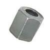
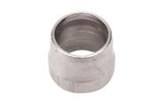
PART No. NUT & OLIVE FITTINGS
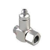
6103768 Alemlube elbow connector 6mm tube x M6/1 (90 deg)
2103859 Alemlube elbow connector 6mm tube x M6/1 (90º) stainless steel
6103736 Alemlube elbow connector 6mm tube x M8/1 (90 deg)
2103860 Alemlube elbow connector 6mm tube x M8/1 (90º) stainless steel
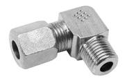
6103767 Alemlube elbow connector 6mm tube x M10/1 (90 deg)
2103853 Alemlube elbow connector 6mm tube x M10/1 (90º) stainless steel
6400081 Alemlube elbow connector 6mm tube x 1/8” BSP (90 deg)
2104042 Alemlube elbow connector 6mm tube x 1/8” BSP (90º) stainless steel
6400140 Alemlube elbow connector 8mm tube x M10/1 (90 deg)
6129403 Alemlube elbow connector 8mm tube x 1/8” BSP (90 deg)
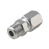
6101086 Alemlube straight connector 6mm tube x M6/1
ADJUSTABLE PUMPING ELEMENT MAINTENANCE

• Remove the screw (1) and extracts: Spring ( 2 ), spring adaptor ( 3 ), seal ( 4 ) and piston ( 5 ).

• Accuratecy clean all the parts and the delivery valve seat ( 6 )
• Attention if the spare part for the seal ( 4 ) is not available it is possible to flip it over and reinstall.
2101228 Alemlube straight connector 6mm tube x M6/1 stainless steel
6101047 Alemlube straight connector 6mm tube x M8/1
2101233 Alemlube straight connector 6mm tube x M8/1 stainless steel
6101048 Alemlube straight connector 6mm tube x M10/1
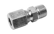
2101232 Alemlube straight connector 6mm tube x M10/1 stainless steel
6400120 Alemlube straight connector 8mm tube x M10/1
6400298 Alemlube straight connector 6mm tube x 1/8” BSP
2101424 Alemlube straight connector 6mm tube x 1/8” BSP stainless steel
5100433 Alemlube cap nut for 6mm tube
5100652 Alemlube cutting olive 6mm tube
5100372 Alemlube cap nut for 8mm tube
5100641 Alemlube cutting olive 8mm tube
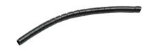
PART No. TUBE & HOSE
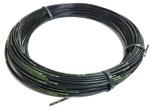
5125622-100 Alemlube tube nylon 6mm dia 70 bar grease filled (100m rolls)
5125622-20 Alemlube tube nylon 6mm dia 70 bar grease filled (20m rolls)
5125623-100 Alemlube tube nylon 6mm dia 70 bar empty (100m rolls)
5125623-20 Alemlube tube nylon 6mm dia 70 bar empty (20m rolls)
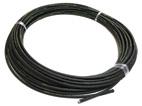
5115478-50 Alemlube hose 8.3mm dia 280 bar grease filled (50m rolls)
5115478-10 Alemlube hose 8.3mm dia 280 bar grease filled (10m rolls)
5115481-50 Alemlube hose 8.3mm dia 280 bar empty (50m rolls)
5115481-10 Alemlube hose 8.3mm dia 280 bar empty (10m rolls)
5115480-50 Alemlube hose 11.2mm dia 280 bar grease filled (50m rolls)
ALSSR-25MM Alemlube hose spiral cover protection (plastic) – per metre
5125622-100 tube 6mm
43 42
1 2 3 4 6 5 1 2 3 4 5 6 6400298 6400081 5100652
5100433
5115478-50 hose 8.3mm
ALEMLUBE GREASE TUBE, HOSE & FITTINGS
PART No. HOSE END FITTINGS
5116883 Alemlube 8.3mm hose end sleeve
5116881 Alemlube 11.2mm hose end sleeve
1000774 Hose end sleeve 8.3mm – stainless steel
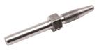
5500134 Alemlube 8.3mm hose end stud, straight - 18mm long
5500344 Alemlube 8.3mm hose end stud, straight - 24mm long

5500085 Alemlube 8.3mm hose end stud, straight - 30mm long
1000770 Hose end stud straight 30mm – stainless steel
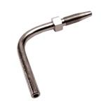
5152997 Alemlube 8.3mm 90° hose end stud - 21mm long
1000773 Hose end stud 90° 28mm – stainless steel
5500156 Alemlube 8.3mm 90° hose end stud - 33mm long
5500216 Alemlube 8.3mm 90° hose end stud - 38mm long
5500247 Alemlube 8.3mm 90° hose end stud - 50mm long
5500099 Alemlube 8.3mm 45° hose end stud
1000771 Hose end stud 45° 30mm – stainless steel
5500136 Alemlube 11.2mm hose end stud, straight 22mm
5128787 Alemlube 11.2mm 45° hose end stud
5500152 Alemlube 11.2mm 90° hose end stud - 35mm long
5500832 Alemlube 11.2mm 90° hose end stud - 55mm long
BT0544 Alemlube 8.3mm reusable 7/16” JIC hose end with sleeve
BT0544S Alemlube 8.3mm reusable 7/16” JIC hose end with sleeve – stainless steel
BT0566 Alemlube 8.3mm reusable 7/16” JIC 90° hose end with sleeve
100120200
-0704 Alemlube 8.3mm swaged 7/16” JIC hose end with sleeve
ALEMLUBE GREASE TUBE, HOSE & FITTINGS
PART No. HEADER BLOCKS
6131 Alemlube header block 1 outlet comes with 6mm fittings and grease nipples
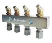

6132 Alemlube header block 2 outlets comes with 6mm fittings and grease nipples
6133 Alemlube header block 3 outlets comes with 6mm fittings and grease nipples
6134 Alemlube header block 4 outlets comes with 6mm fittings and grease nipples
6135 Alemlube header block 5 outlets comes with 6mm fittings and grease nipples
6136 Alemlube header block 6 outlets comes with 6mm fittings and grease nipples
6138 Alemlube header block 8 outlets comes with 6mm fittings and grease nipples
PART No. ADAPTOR FITTINGS
5116763 Alemlube adaptor M8/1 male x M10/1 female - 21mm long
9900153 Alemlube adaptor M10/1 male x M10/1 female - 21mm long
1000696 Alemlube adaptor 1/8” BSP male x M10/1 female - 21mm long
5128982 Alemlube adaptor 1/8” BSP male x 1/8” BSP female - 21mm long
1000571 Alemlube adaptor M6/1 male x M10/1 female - 24mm long
5116734 Alemlube adaptor M10/1 male x M10/1 female - 50mm long
5116753 Alemlube adaptor M10/1 male x M10/1 female - 35mm long
5116752 Alemlube adaptor M8/1 male x M8/1 female - 35mm long
1000295 Alemlube adaptor 1/4” BSP male x M10/1 female - 26mm long
PART No. UNIONS & BULKHEADS
6105688 Alemlube union 6mm tube joiner
2105768 Alemlube union 6mm tube joiner – stainless steel
1000833 Alemlube bulkhead 6mm with grease nipple
1000685 Alemlube bulkhead union 6mm
2106978 Alemlube bulkhead union 6mm – stainless steel
1000686 Alemlube bulkhead union 8mm
5500136
9900417 Alemlube 45° elbow M10/1 male x M8/1 female
5901017 Alemlube 45° elbow M8/1 male x M8/1 female
5116796 Alemlube 90° elbow M8/1 male x M8/1 female
5126044 Alemlube 90° elbow M6/1 male x M10/1 female
5126046 Alemlube 90° elbow M8/1 male x M10/1 female
5126797 Alemlube 90° elbow M10/1 male / female
1000272 Alemlube 90° elbow 1/8” BSP male x 1/8” BSP female
6105688
FAVSS8404 Alemlube bulkhead 1/4”BSP(f) x 7/16” JIC(m) – stainless steel 1000833
45 44
5116883
5500247
ALSSR-25
6134 5116734 5116796 1000272
ALEMLUBE GREASE TUBE, HOSE, FITTINGS & HEADER BLOCKS
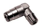
PART No. PUSH-IN HIGH PRESSURE FITTINGS
H0040130 Alemlube 90° elbow 6mm tube x M6/1
H0040530 Alemlube 90° elbow 6mm tube x M8/1
H0040630 Alemlube 90° elbow 6mm tube x M10/1
H0040031 Alemlube 90° elbow 6mm tube x 1/8” BSP
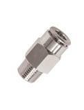
H0010130 Alemlube connector 6mm tube x M6/1
H0010530 Alemlube connector 6mm tube x M8/1
H0010630 Alemlube connector 6mm tube x M10/1
H0010031 Alemlube connector 6mm tube x 1/8” BSP
H0080130 Alemlube swivel elbow 6mm tube x M6/1
H0080530 Alemlube swivel elbow 6mm tube x M8/1
H0080031 Alemlube swivel elbow 6mm tube x 1/8” BSP
H0080032 Alemlube swivel elbow 6mm tube x 1/4” BSP
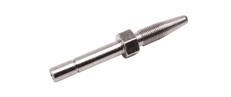
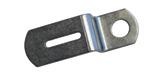
ALEMLUBE TRUCK BRACKETS
• SK4083 - Floor Mount Pump Bracket
• 08005001-KW-3P - Wing Mount Pump Bracket
• 0800800601 - Western Star Bracket
PART No. PUSH-IN HOSETAILS

1001062G Alemlube 8.3mm straight hose end stud - 24mm long
5500304G Alemlube 8.3mm straight hose end stud - 30mm long
1001050G Alemlube 8.3mm 90° hose end stud - 32mm long
1001054G Alemlube 8.3mm 90° hose end stud - 50mm long
1001058G Alemlube 8.3mm 45° hose end stud - 68mm long
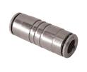
PART No. MEDIUM PRESSURE PUSH-IN TUBE UNION
M0160030 Alemlube union 6mm tube joiner
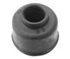
PART No. DUST COVER FOR PUSH-IN FITTINGS
DCPI6 Alemlube dust cover – one required per fitting
• 0800800602 - Angled K200 Pump Bracket

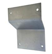


• 08005001AU - 90 Degree Wall Mount Pump Bracket
• SK4095 - Wall Mount Pump Bracket
• SK4096 - DPX Divider Mounting Bracket

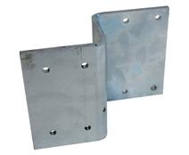
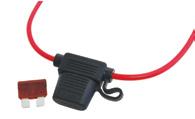
• FUSE - 5a Blade Fuse And Holder
47 46
H0040031 5500156 H010530 M0160030 DCPI6
ILC MAX CRITICAL SPARE PARTS
• 40.CPT.00 ILC MAX PROTECTIVE COVER FOR CONTROLLER
• 40.CCT.DC.05 ILC MAX REPLACEMENT CONTROLLER


• 40.PWR.74.BT.DC ILC MAX SIDE PANEL FOR PUMPS WITH CONTROLLER

• A70.093531 ILC MAX 12DC/24DC BOTTOM COVER
• A89.128043 ILC MAX 2KG REPLACEMENT RESERVOIR BOWL


• A78.129125 ILC MAX 4KG REPLACEMENT RESERVOIR BOWL
49 48
NOTES
ALEMLUBE WARRANTY POLICY
Your Alemlube product is warranted to the original user against defects in workmanship or materials under normal use for a period of twenty four months after purchase date. Any product which is determined to be defective in material and workmanship and returned to Alemlube P/L, shipping costs prepaid, will be repaired or replaced at Alemlube’s option. This warranty also covers parts that are subject to wear such as O rings, packings, seals, springs, electronic and even electrical components. The warranty does not cover damage or failure which in the judgement of Alemlube arises from misuse, abrasion, corrosion, negligence, accidental damage, faulty installation or tampering.
If Alemlube inspection discloses no defect in material or workmanship, repair or replacement and return will be made at customary charges.
Alemlube has made a diligent effort to accurately illustrate and describe its product in all its literature. However, such illustrations and descriptions are not a warranty.
The above express warranty is in lieu of and excludes all other warranties, express or implied, including, without limitation, merchantability or fitness for a particular purpose. The purchaser shall give written notice of any claim to Alemlube within ten days after discovery of any alleged defect.
Alemlube shall not be liable for consequential damages, losses, delays, labour costs or any other expense directly or indirectly arising from use of the product, its liability being expressly limited on the replacement or repair of any defective product or an allowance of credit therefore.
The remedy and recovery of the purchaser on any claim against Alemlube, whether based on contract of this warranty or any alleged negligence shall be as stated and limited herein and shall be exclusive.
Alemlube warranty on Automatic Lubrication Systems, Vehicle Hoists, Wheel Service Equipment and other products installed by Alemlube is twenty four months after purchase date, unless otherwise stated at the time of purchase.
Proof of purchase including the pump/product serial number will be required to initiate a warranty claim. Claims relating to damage or wear and tear of Alemlube installed products and/or installation materials will be assessed by Alemlube taking into account the actual working conditions and reasonable care and maintenance on behalf of the purchaser. Warranty is void if any alterations, modifications or repairs are attempted without the express permission of Alemlube.
*For inclusions and exclusions please visit our website to confirm details.
51 50
NOTES