ARCHITECTURE
PORTFOLIO
Alba Punset
Junior Architect
2023/10 - Present
2022/06 - 2023/09
B15 Arquitectura, Madrid, Spain | Architectural firm
Involvement in new construction architectural projects:
» Residential complex of 54 single-family houses in Madrid
» Multi-story collective housing complex in Madrid
» Semi-detached housing development in Madrid
» Hospital in Fuerteventura
Involvement in architectural restoration projects:
» Restoration of a Convent in Valladolid for residential and wedding venue use
» Restoration of a Hospital in Fuerteventura
Key responsibilities included:
» Development of Concept and Detailed Design Preparation of technical reports | Layouts in Revit and AutoCAD | Client meetings
Junior Architect
M+V and Partners, Madrid, Spain | Architectural and Interior Design firm
Involvement in international projects:
» Coorporate offices in Milan and Singapore
» Hotel in Saudi Arabia
» ICE in Polytechnic Faculty of Madrid
» Family House Unit in Madrid
Key responsibilities included:
» Design Development
Moodboards | ayouts and visualitazions for Concept and Detail Design | Presentations for the client
» Project Management
Procurement management | Teams and suppliers coordintation
» Site Management
Construction agents coordination | Client meetings | Site reports | On-site problemsolving
2023/01 - 2024/09
2021/02 - 2022/02
2015/09 - 2021/01
2018/09 - 2019/07
Revit Architectural Course
Editeca, Online school of Design, Architecture, Engineering and New Technologies
Architecture Master
ETSAM, Polytechnic University of Madrid, Spain
Architecture Degree
ETSAM, Polytechnic University of Madrid, Spain
Erasmus | Architecture Degree
University of Split, Croatia

Contact


albapunsetm@gmail.com +34 689152142

linkedin.com/in/alba-punsetmedina
Date of birth: 08/02/1997
Place of birth: Madrid, Spain
Software
Revit Advanced
AutoCad Advanced
Rhinoceros Advanced V-Ray Rhinoceros Intermediate
Photoshop Advanced
Adobe InDesign Advanced
Microsoft Office Advanced
SketchUp Intermediate
CYPECAD Intermediate
Languages
English Advanced | C2 level
Spanish Native
Interests
Interior Design
Painting
Multi-story collective housing in Madrid
Multi-Functional Skycrapper: Culture, Offices & Residential 01 02 03 04 05 06
HCF
Hospital in Canary Islands
AKH
Hotel in Saudi Arabia
ICE
Institute of Education Sciences Refurbishment
THROUGH THE LIMIT
Cultural & Gastronomic Center
PIXEL TOWER
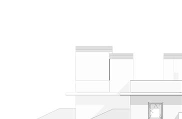
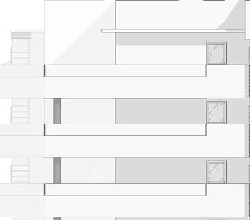
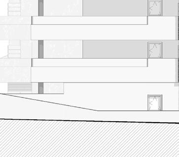
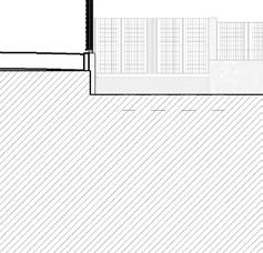
Architecure | Multi-story collective housing complex in Madrid
Design & Site Management | B15: 2020-2025
LOCATION: Madrid
DECRIPTION
The 152-unit residential complex, located on the outskirts of Madrid, aims to foster a strong sense of community by seamlessly blending private and shared experiences. Generous common areas, including gardens, swimming pools, and padel courts, enhance this connection among neighbors.
The apartment layouts are designed to balance comfort and efficiency, featuring premium materials.
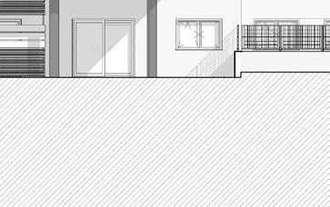
A modern, open design, accentuated by expansive glazed terraces, creates a high-quality and inviting living environment.
B15 SCOPE OF WORKS:
• Concept Design (design in Revit and AutoCAD).
• Detailed Design (design in Revit and AutoCAD).
• Construction Site Management.

Due to the current housing shortage in the city of Madrid, residential urban areas are beginning to expand into the surrounding towns.
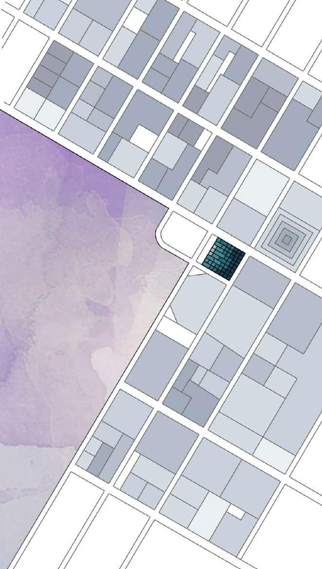
The project is located in the southeastern part of the city, in one of the fastestgrowing urban areas on the outskirts of Madrid, just 25 km from the city center. Unlike other towns that have become commuter cities, this area is equipped with proper infrastructure, including schools, healthcare centers, and good connections to the city center, making comfortable living possible.
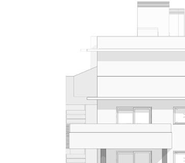
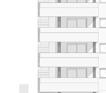
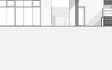
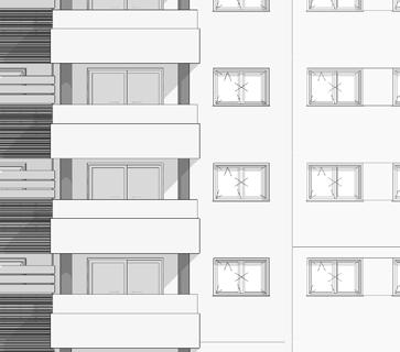
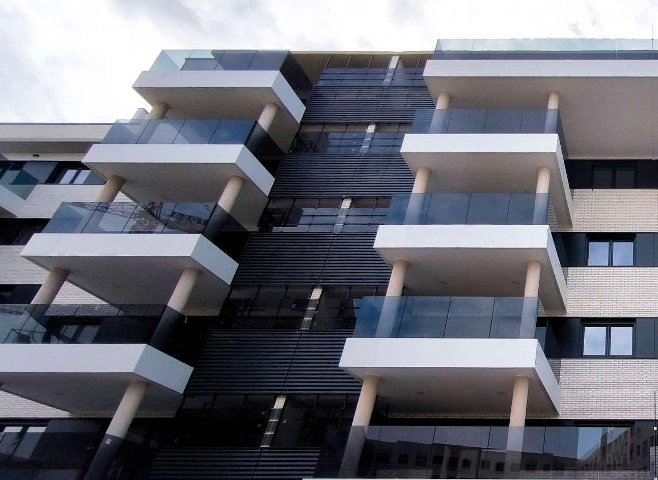
Each apartment is designed with two façades: one facing the street and the other opening up to the common areas of the complex. This design allows two different options depending on the client’s preferences and needs: one with the terrace overlooking the gardens and swimming pools, and the other with the terrace facing the street.
A variety of housing typologies, from two-bedroom residences to spacious penthouses, have been carefully designed to meet diverse needs, promoting the creation of a dynamic and inclusive community
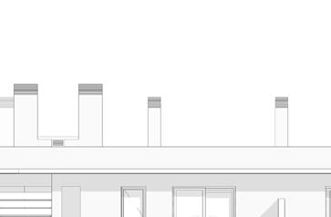
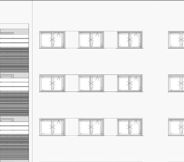
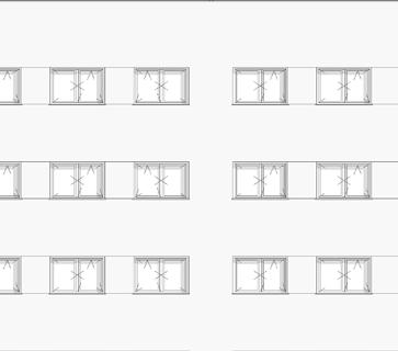
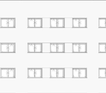
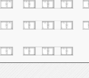
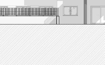
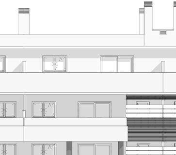
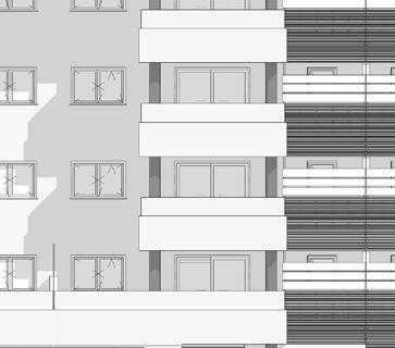
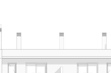
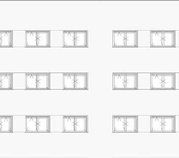
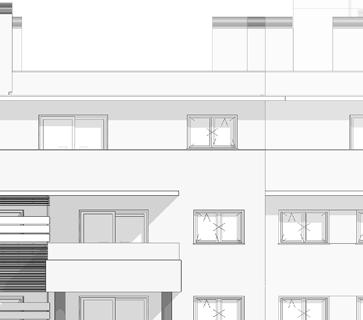
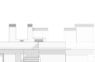
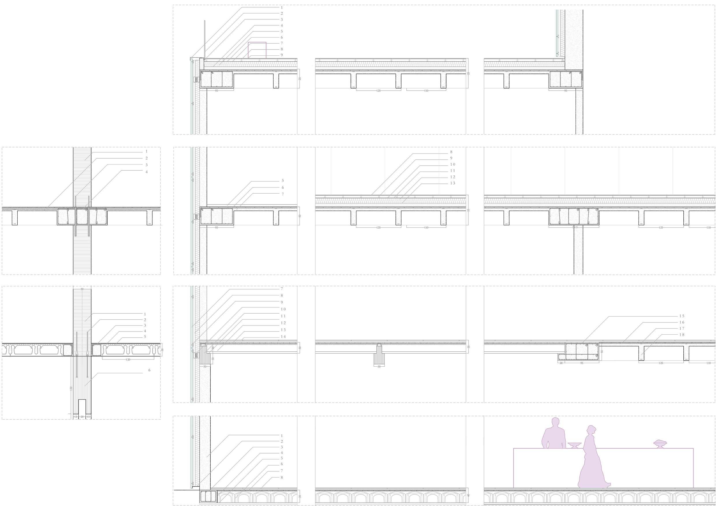
Two distinct façade typologies are proposed: one, more solid and introverted, facing the exterior to enhance acoustic insulation and ensure privacy, and another, more open and expansive, oriented towards the interior of the development. This second façade is designed to foster a sense of calm and community, offering views of the landscaped gardens and swimming pool, thereby creating a harmonious connection between the private and communal spaces.
A variety of materials are combined: the primary material is white brick, used across most of the building, complemented by Alucobond cladding on the terraces. The dark aluminum framing for windows and laundry terraces introduces a striking contrast to the light-toned façade.


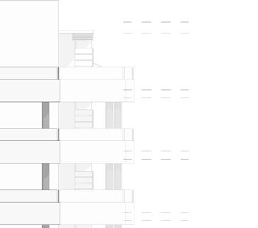


1mm aluminum U-profile
L-profile 40x45x2 mm
8 mm welded plates
100x100x10 laminated profile welded to bracket and to 8 mm plate
Terrace column
10mm+10mm laminated glass with butyral
Perimeter infill of the raised floor
Raised floor on plots
Pillar-to-floor finishing profile
suspending ceiling
1mm aluminum U-profile
L-profile 40x45x2 mm
Neoprene side shims
T-profile aluminum alloy 6063-T6, joints every 4 m
Levelling and gripping screw
L-profile 30x30x2.5 mm welded to plate
8 mm welded plates
10+10 laminated glass with butyral
100x100x10 laminated profile welded to plate
Lower neoprene shim
8 mm welded plates
Alucobond Traffic White, 2 sheets of Al EN
100x100x10 laminated profile welded to bracket and to 8 mm plate
AW-5005-A H22 of 0.5 mm and mineral core Bs1-d0, with adhesive fixation using Sika Tack Panel system
Bracket 150x150x8 mm anchored to slab with 2 dowels Ø8 mm L=25 cm
Ø40mm hole for welding the plates on the inner side
Screw with structural anchor
Expansive leveling mortar
100x100x10 laminated profile welded to bracket and to 8 mm plate
Terrace slab
T-profile aluminum alloy 6063-T6, joints / 4 m.
Screw with structural anchor Levelling and gripping screw
L-profile 30x30x2.5 mm fixed to slab with screws
Levelling and gripping screw
L-profile 30x30x2.5 mm welded to plate
L-profile 40x45x2 mm
Alucobond Traffic White, machined folding
Neoprene side shims
T-profile aluminum alloy 6063-T6, joints every 4 m
Ø40mm hole for welding the plates on the inner side
Levelling and gripping screw
100x100x10 laminated profile welded to bracket and to 8 mm plate
L-profile 30x30x2.5 mm welded to plate
8 mm welded plates
10+10 laminated glass with butyral
100x100x10 laminated profile welded to plate
Lower neoprene shim
Alucobond Traffic White, 2 sheets of Al EN
AW-5005-A H22 of 0.5 mm and mineral core Bs1-d0, with adhesive fixation using Sika Tack Panel system
Bracket 150x150x8 mm anchored to slab with 2 dowels Ø8 mm L=25 cm
Screw with structural anchor
Expansive leveling mortar
Terrace slab
T-profile aluminum alloy 6063-T6, joints / 4 m.
Screw with structural anchor
Levelling and gripping screw
L-profile 30x30x2.5 mm fixed to slab with screws
8 mm welded plates
Hole for grip
Architecure | Hospital in Canary Islands
Design | B15: 2024-present
LOCATION: Canary Islands
DECRIPTION
In the eastern part of the island, where the project is located, the objective is to expand healthcare facilities by extending an existing hospital. This will be achieved by repurposing the adjacent plot, currently occupied by the ruins of an abandoned nightclub.
Given its designation as a historic building, a thorough study has been conducted to determine which elements should be preserved, restored, or integrated, ensuring harmony between the new design, the existing context, and the hospital’s functional requirements.
The greatest challenge lies in balancing the preservation of key architectural elements with the seamless integration of the new hospital facilities. The site, formerly a nightclub, must be adapted while maintaining strong connections to the existing hospital. Certain remnants of structures with ethnographic value are carefully preserved and enhanced. Additionally, significant portions of the northern and eastern party walls are retained, while select elements—including sections of the wall, a hydraulic tile floor, and a water reservoir—are relocated to maintain their historical significance within the new development.
B15 SCOPE OF WORKS:
• Concept Design and Detailed design

The floor plan is developed through a detailed analysis of the walls designated for preservation, ensuring their integration into the hospital’s new spatial organization. Circulation cores are strategically positioned in response to these constraints.
During the demolishing process, a subterranean historial cistern was discovered and needed to be preserved, becoming a key element that shapes the spatial configuration of the basement level and groundfloor where a glazed courtyard is creater in order to offer views of the cistern to highlight its historical value.
The project aims to develope a building that will house an Emergency Center on the ground floor, a set of consultation rooms on the first floor, and a series of patient rooms on the second floor:
• Ground floor: reception, blood analysis, laboratory room, casting room, observation room, examination boxes, and service areas.
• First floor: consultation rooms, nursery room, and service areas.
• Second floor: patient rooms, nursery room and service areas.
In order to preserve the historical character of the building, the restoration of the original ground-floor façade is planned. This is integrated with a ventilated façade, featuring a ceramic exterior finish and a concealed mechanical anchoring system combined with a glass façade and louvers to provide privacy while allowing natural light into the consultation rooms, for the upper floors.


Design & Site Management | M+V and Parnters: June-October 2022
LOCATION: Al-Khobar, Saudi Arabia
DECRIPTION
In the Arab city of Al-Khobar this hotel is developed with the aim of providing the building with a strong and attractive interior design concept.
To achieve this, the interior architecture of the hotel is inspired in the local lanscape which surrounds the city: Dammam Desert and its dunes, Jebel Qarah caves and Al-Ahsa Oasis. Some materials as microcemt, wood or bronze intend to remain the tones and textures of these landscapes. These materials are combined with more classic materials, mainly marble in order to include a touch of the Arab Design Style in this country.
Organic shapes define the partitions, flooring patterns and ceilings through the different areas. However these curved lines are broken by straight lines at some spaces to add contrast and avoid a monotonous athmosphere.
M+V SCOPE OF WORKS:
• Concept Design, including moodboards, layouts, BOQ and 3DVisualizations.
• Detailed Design (by M+V Spain & M+V Italy).
• Procurement Management.
• Partner Team Coordination

The concept for these two areas is inspired by the desert organic shapes and tones in order to be stablish a connection with the lanscape which surrounds the city where it is located.
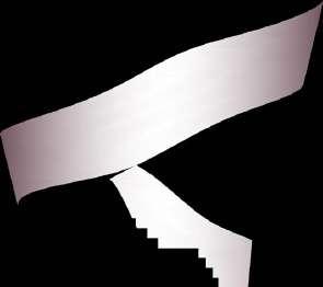
The main element of this space is the entrance’s wavey stairs, made in bronze resine.
This organic shape is transfered to the slats ceiling inspired in the desert dunes.
Different materials are combined in the floor and walls. The walls, finished on Travertine Ocean Grey, remains of the local caves, Jebel Qarah, but providing a cold tone to the desert athmosphere.
For the flooring two different materials are combined by curved joints following the organic concept in these floors: Cement Design concrete finish, remaining the sand, and Calacatta Marble, providing an elegant touch.
The Ground Floor is composed by three areas.
• The Lobby entrance.
• The Restaurant which is visually connected to the outdoor space.
• Lounge Area.
The Mezzanine intends to be a continuation of the Ground Floor but also a more private space where a restaurant area is developed.


As per the client request, this floor intends to contrast with the rest of the hotel concept.
The restaurant is willing to be an oasis in the desert.
Organic shapes are mainly replaced by straight lines in the flooring and walling, warm tones are replaces by cold tones and a touch of green remaining the vegetation as an oasis.
Regarding the space distribution, four different spaces are established:
• Waiting area
• High sitting area
• Lounge area
• Outdoor space for terraces.
The spaces are divided by the flooring marble pattern, using a different configuaration and material for each area.
B


By combining brown, beige, blue and grey tones, a contrast between warm and cold tones is created as transition between the Ground floor & Mezzanine, which are based on warm tones and organic space, and the Restaurant and Wellness floor, which are based on cold tones and straight lines.
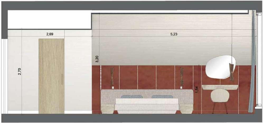
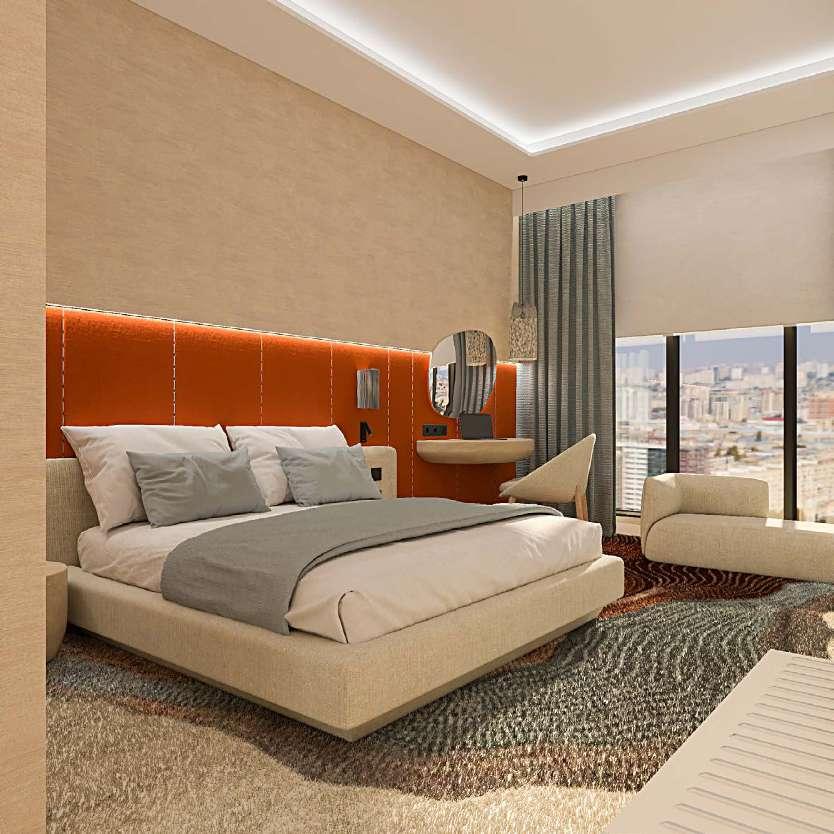
The main element of the room is the carpet which is inspired in the Al Qarah Mountain.
For the bathroom concept neutral colours and clean distribution are stablished in order to created a calm and elegant space, where classic materials, Calacatta Vagli Oro Marble, are combined with more innovative ones, Cement Design concrete wall finish.


A Section B
Design & Site Management | M+V and Parnters: June-October 2022
LOCATION: Polytechnic University of Madrid, Spain
DECRIPTION
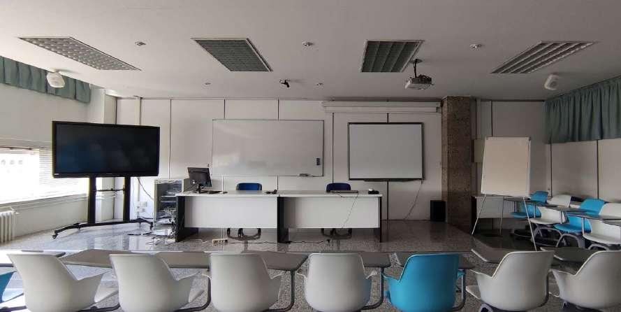
Initially the Institute of Education Science, belonging to the Polytechnic University of Madrid, was suffering of an unappropiate space distribution and lack of lighting, as well as some spaces for storage or professors were not practical and barely used.
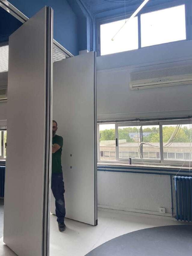
The porpouse of the project is, on the one hand, to improve these aspects by connecting classrooms and providing them of the possibility to create diaphanousdivided classrooms by movable panels.
On the other hand, the non-used spaces are redesign to keep only the neccessary ones by providing them and the classrooms proper dimensions and functionality.
M+V SCOPE OF WORKS:
• Design & Execution Project.
• Site Management.
• Suppliers Coordination.
• Client Coordination.
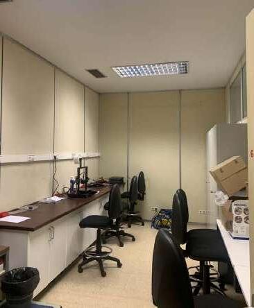
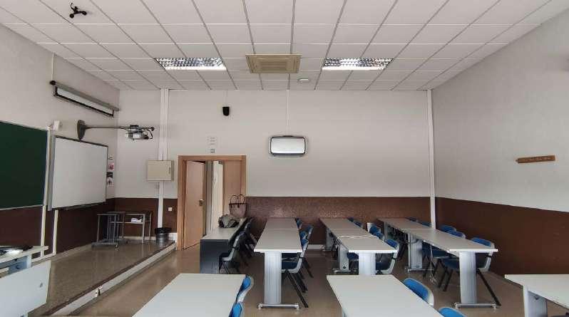
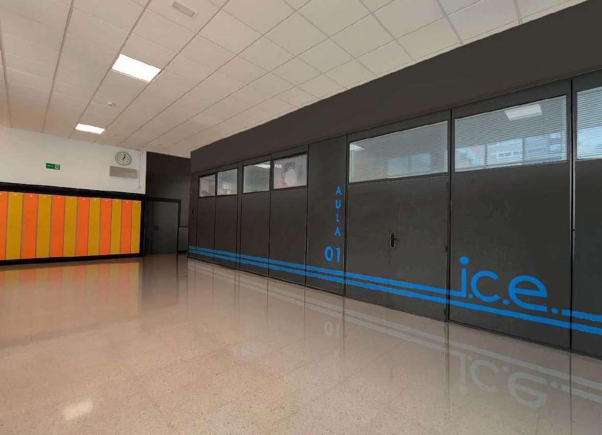
Before the refushment, the spaces dedicated to the ICE were not properly connecting, leaving small classrooms with poor lighting.
Apart from the classes an unappropiate distribution was shown also in the storage rooms and professors rooms. These areas didn´t provide enough space for its function and were barely used produting in fact a residual space, specially the professor rooms due to there is a big space with offices for them in the upper floor.
To improve this aspects the project has 3 main goals:
• To connect spaces and provide flexibility in the classrooms.
• Increase the natural lighting.
• To re-distribute the space, specially the storage and professors rooms, and where necessary to eliminate the nonused spaces.

SECTION A SECTION B
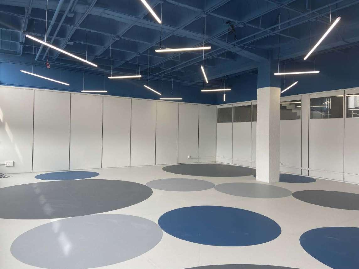
The main concern from the client was to creat a dynamic and flexible space, where diferent types of configuration may be done in the work space.
To achieve this, in first place mobile partitions are created to provide the possibility of having either 2 big diaphanous classrooms or 4 classrooms dived by these acoustic Tabitek mobile panels.
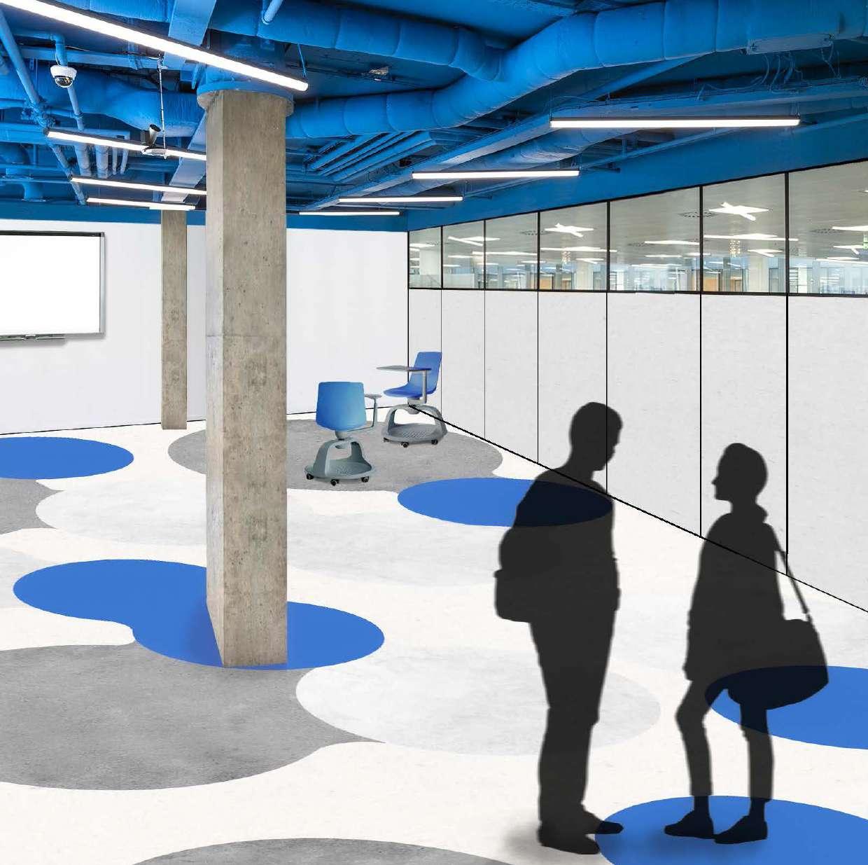
In second place a combination of different diameters is established in order to create 3 typologies of work groups: 3 people, 6 people and 9 people. This circles are reflected in the plan by a custom Gerflor vynil flooring.
This game of cricles, which takes place in the working groups and the floor, produces a continuous movement flow through the classroom.
As there is no an established tables distribution, but a flexible one, it is neccessary to provide a difuse lighting through all the classroom. In order to achieve this, an homogeneus LED lighting distribution is established to acheive a proper lighting through the whole wroking space.
EVOLUCIÓN_DEL_PATRÓN_1
EVOLUCIÓN_DEL_PATRÓN_2
EVOLUCIÓN_DEL_PATRÓN_3
CLASSROOM 1.1
CLASSROOM 1.2 SERVER ROOM STORAGE
Regarding the elevations, the main aim of the project is to increase the natural lighting and to create continuity through all the spaces.
In order to increase the natural lighting, the false ceiling is demolished, showing the structure composed by waffle slab which is painted in the coorporative ICE blue colour, as well as the intallations (MEP, HVAC) and the upper area of the walls
The walls are painted in white tones until the height of the acoustic panels in order to create a continious wall when the classrooms are divided.
Cultural and gastronomic center
ARCHITECTURE MASTER: 2021-2022, 1st & 2nd semestre
PROFESSOR: Javier Maroto
LOCATION: Vitoria-Gasteiz, Spain
DECRIPTION
The building seeks to be a meeting point between the two neighborhoods, currently unconnected, and the park. In this way, a program is proposed that activates the area beyond working hours and where different programs are combined to attract and enhance interurban relations. The project consists in a gastronomic and cultural center which includes a market and eating area in relation to the park, restaurant areas, exhibition halls and workshops.
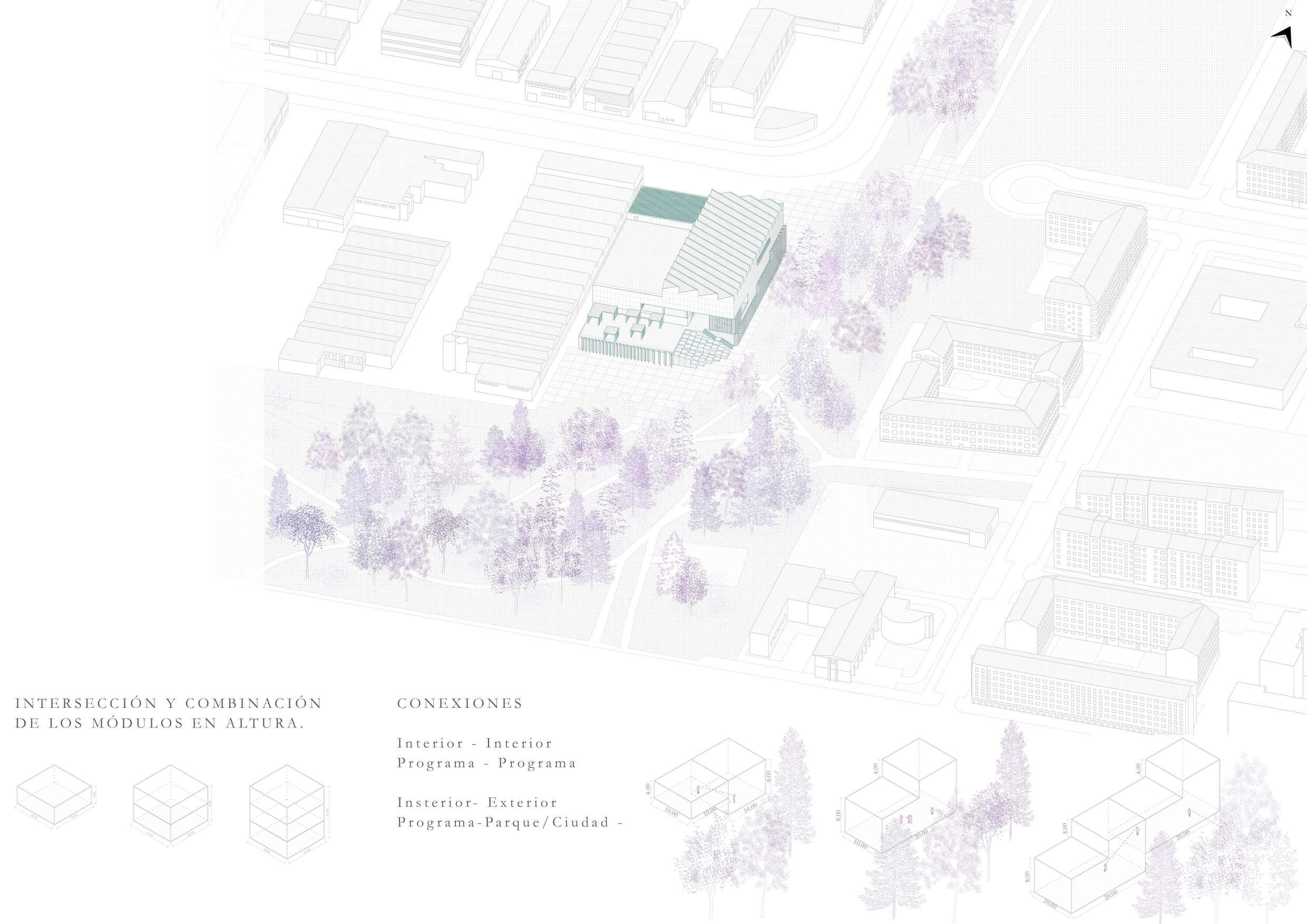
Two types of sections are produced. On the one hand: the isotropic constructive section which follows the 10 x 10 grid. Then, a visual section is superimposed from the park entrance, creating an ascending topography, which marks the diagonal. This diagonal achieves a connection from the first floor to the highest level, intersecting and combining the different programmes in section, integrating neighborhoods and becoming the new cornice of the park.
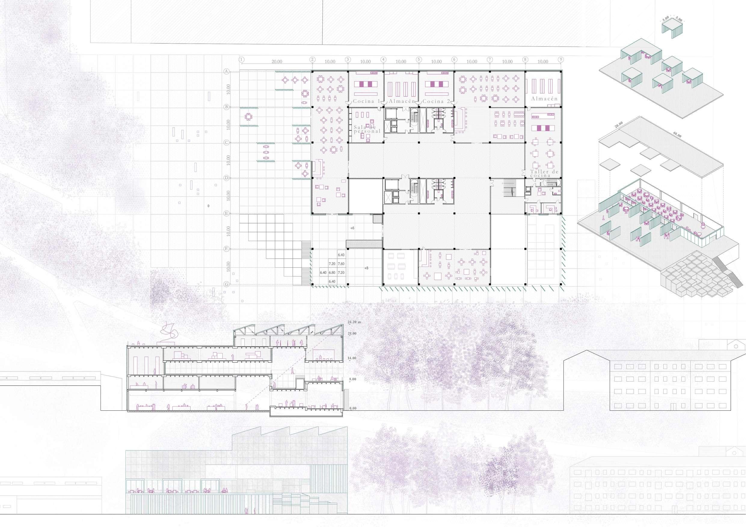
Estimated Surface: 19.800 m2
Maximum hight: 24,20 m.
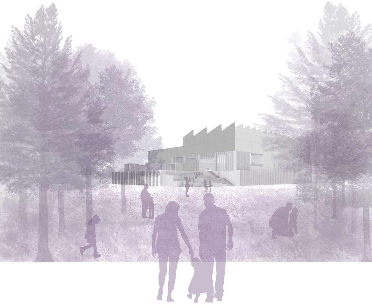

The project is located in the city of VitoriaGasteiz, Basque Country, Spain. The plot is located in the industrial area of AliGobeo, northwest of the city and on the border between the industrial area of AliGobeo, the residential neighborhood of Lakua and Campas de Sansomendi Park.
Due to its location on the edge of the park, it constitude a strategic location to link the industrial and residential areas, currently segregated by the green axis. To this end, the access roads from the park and from Lakua are enhanced, and two access plazas to the building are created:
• Urban access, which connects the building with Lakua and with the industrial area.
• Access from the park.
A grid of 10 meters x 10 meters is established in order to organize the different spaces and heights where the programs are developed. These modules establish relationships between the different programs through double and triple heights, where they intersect.
COMBINATION
Indoor - Indoor Program - Program
Indoor - Outdoor Program - Park/City
4th Floor: Artistic Workshops
A main diagonal section is created in the longitudinal facade of the park, which crosses the building from the Park Entrance to the highest level. In this section the intersections between programs are introduced in order to provide the visitor a partial image of the building.
The programme moves up through the building, from the market to the workshop areas.
Since it also aims to relate to the outside, especially to Campas Sansomendi, it acts as a cornice of the park and some concrete blocks are going up the outside of the building, introducing the outdoor access to the first terrace.
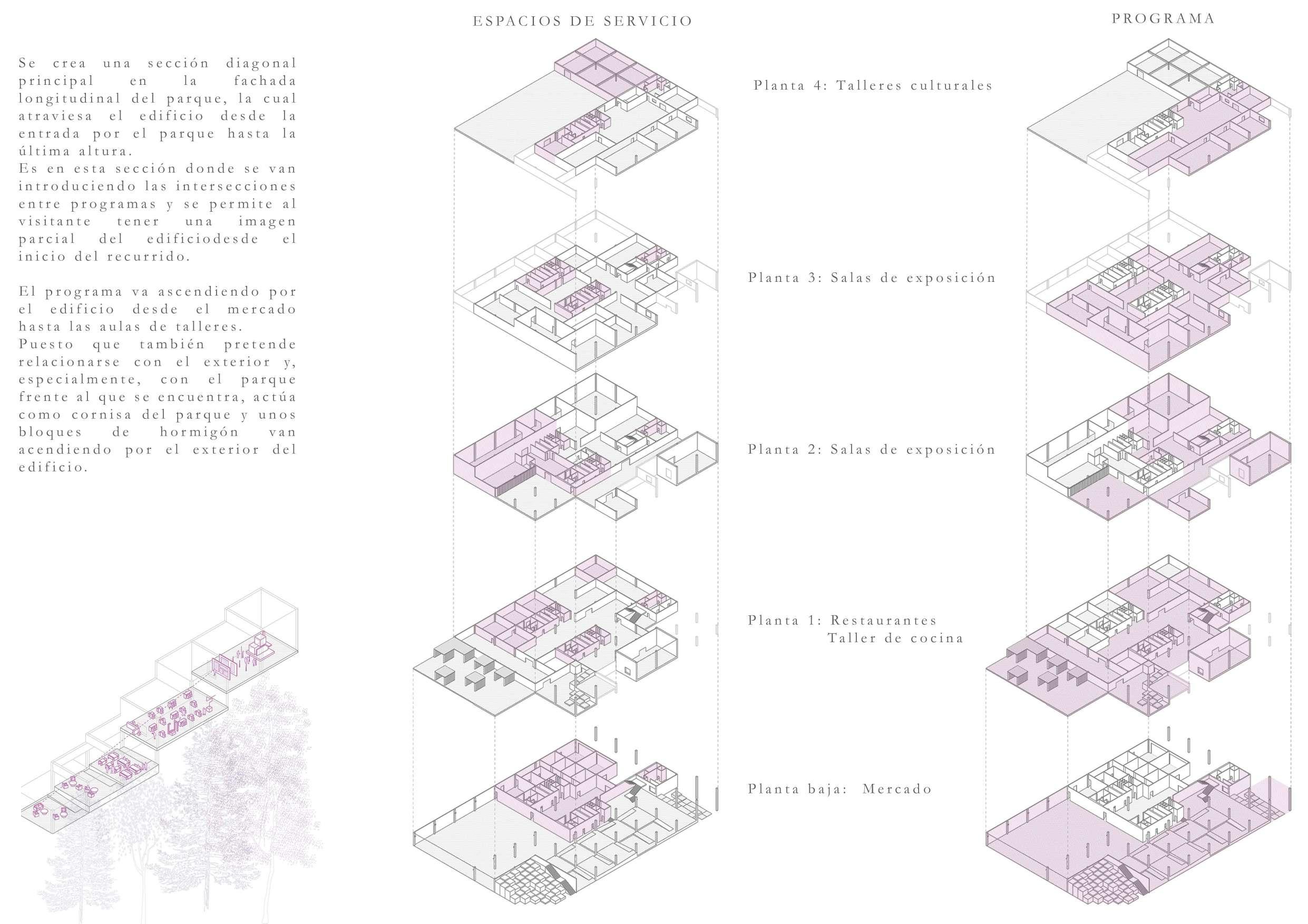
3rd Floor: Exhibitions Spaces
2nd Floor: Exhibitions Spaces
1st Floor: Restaurants Culinary Workshops
Ground Floor: Market
The first floor is intended to be a continuation of the park surrounding the building. For this purpose, two skins are created on the façade:
• A transparent skin by means of a curtain wall, which allows a direct view of the surroundings.
• A second skin of prefabricated concrete slats.
Two main spaces are differentiated on this floor: the market and its dining area. Regarding the market, a diaphanous environment is created without interruption of pillars thanks to large-edged precast prestressed concrete beams. In addition to this main structure, a secondorder structure is stablished: prefabricated concrete beams supported by a lightened preslab.
In the dining area of the market, the grid structure that will be used in the rest of the building, except for the top floor, is introduced. It consists of a bidirectional slab of recoverable caissons and flat beams, which mark the 10 m x 10 m grid which organizes the rest of the building.
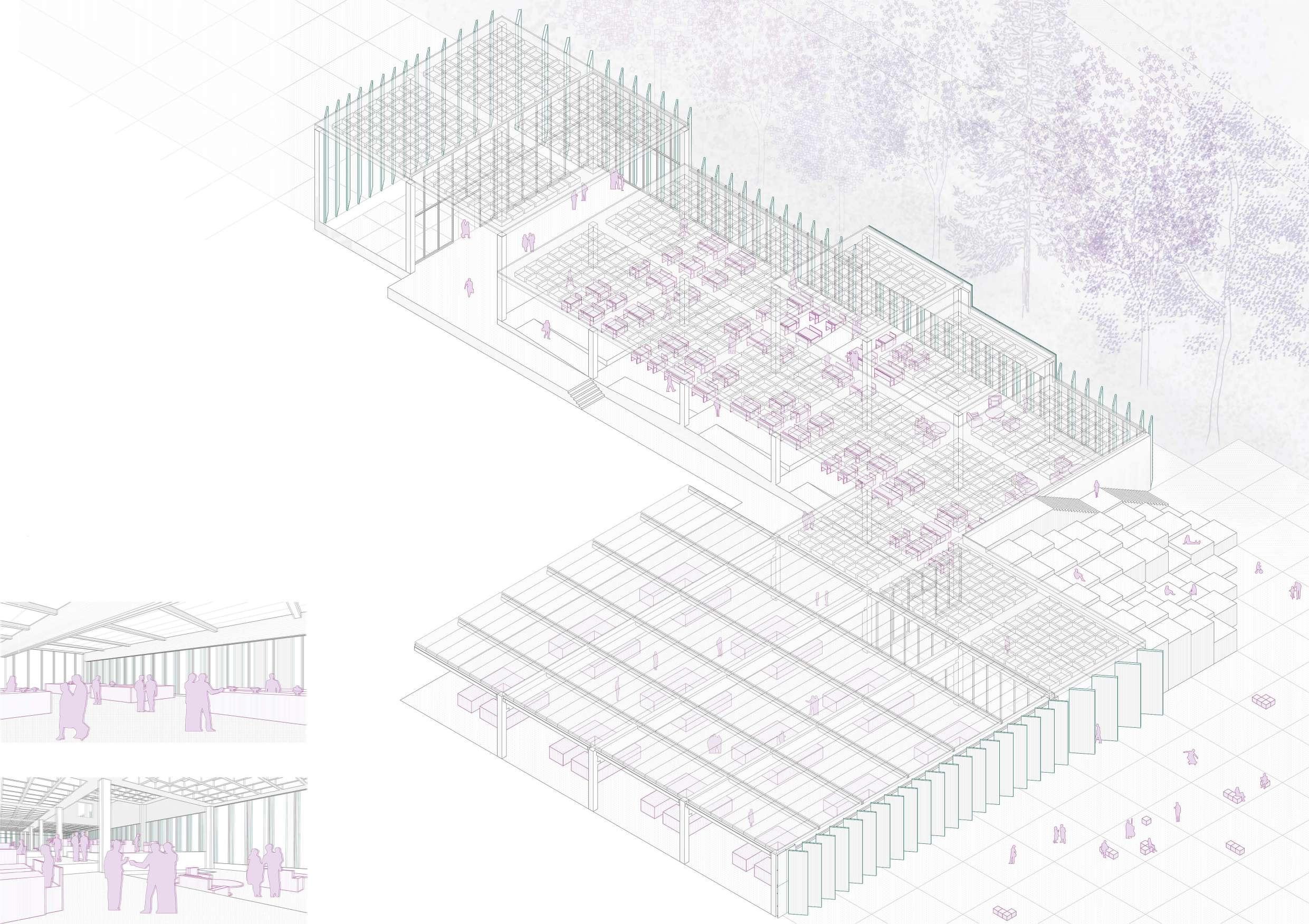
An exterior grandstand is created based on prefabricated concrete blocks, which ascends from the park to the first terrace and creates the third access to the building. At the same time, this grandstand gives rise to an intermediate space between the park and the inside of the building, which is designed for resting and to promote the relationship between visitors and the landscape contemplation.

The creation of the topography extends to the interior through a set of slopes, connected by ramps, which constitute the dining area of the market, and from which views are sought both inside and outside by means of prefabricated concrete slats oriented to the north.
On the first floor, the dining spaces are located, accessible from both the interior and exterior, creating a third access to the building through the grandstand. This way, a first terrace is generated, where the dining programme extends and creates an intermediate space between the park and the complex.
In this space, semi-covered modules measuring 5 meters x 5 meters are designed, which focus the views towards the park.
A

Finally, on the fourth floor, there is a series of workshops, above which are located north-facing skylights to provide them with diffuse lighting. The programme extends to the exterior through a walkable roof dedicated to outdoor exhibitions, which focuses the views towards the park as a backdrop.
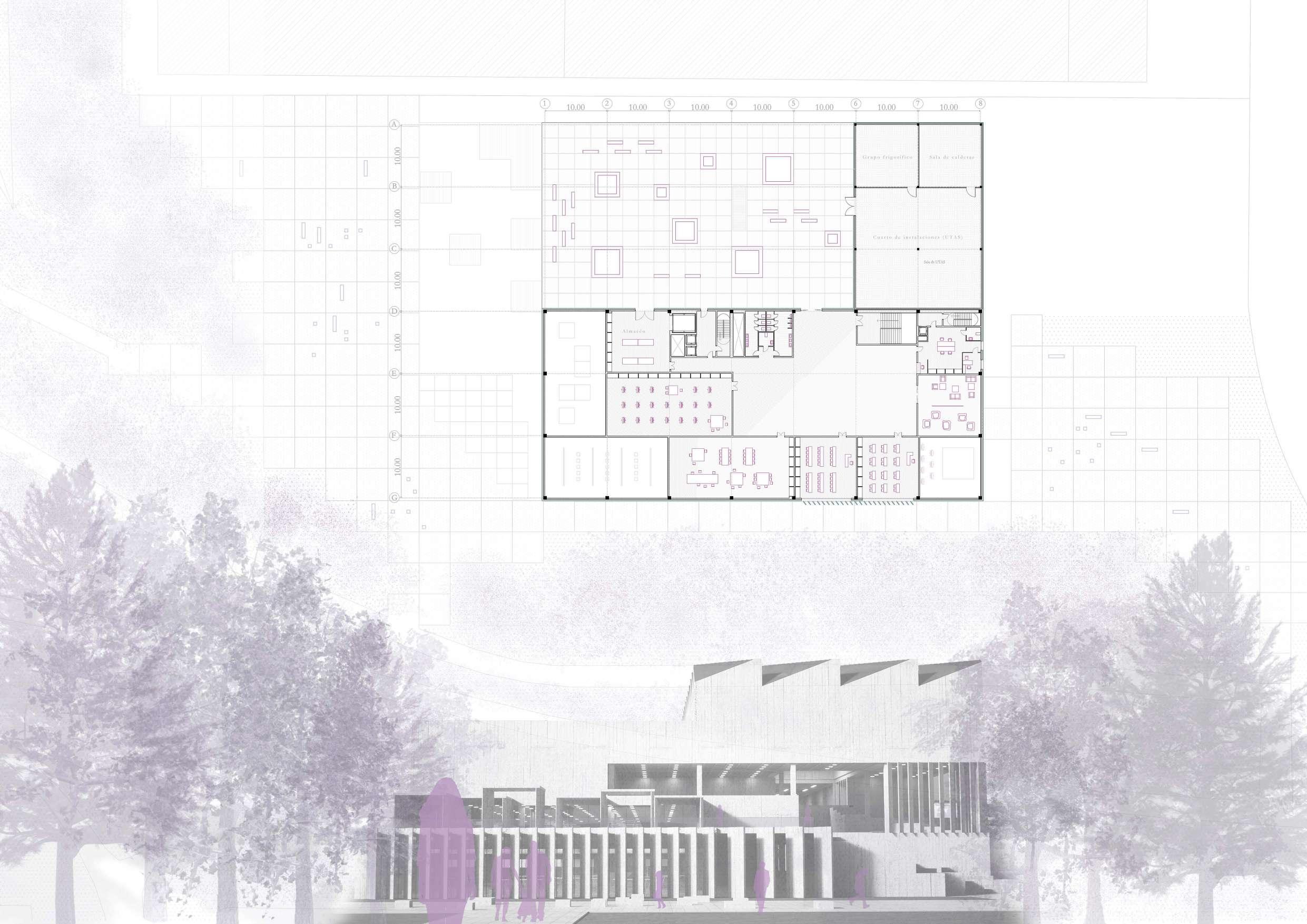
The roof plan is free from pillars and maintained along the perimeter. To cover the large spans of 34 meters, rotated metal skylights are designed, oriented to the north.
In addition to providing diffuse light to the workshop spaces, they traverse different areas and programs through the varying levels of double and triple heights, reaching down to the ground floor in the main section.
On the other hand, to cover the open roof belonging to the utility room, housing the AHUs, boiler room, and refrigeration unit, a metal structure is proposed that continues the direction of the skylights, integrating it into the rest of the building.
3.
METAL STRUCTURE 1
Skylights composed of steel trusses, S 275 grade, with a depth of 3 meters and IPE 300 purlins using end plate connections.
METAL STRUCTURE 2
Aluminum slats with tubular profiles in the direction of the skylights to provide continuity in the roof, with connections made through end plates.
BASE STRUCTURE
It is composed of precast prestressed concrete beams for supporting the metal roofs.

The facades facing the park aim to establish a relationship between the building and the park through a double porous skin composed of a curtain wall and a set of precast prestressed concrete slats. This facade rises from the scale of the park to the scale of the city, resulting in two main entrances to the building, accessed through larger-scale slats.
The next facade consists of a ventilated facade formed by UHPC panels, whose vertical profiles align with the vertical supports of the curtain wall.
The roof of rotated skylights, oriented towards the north, is materialized with a lightweight Kalzip Alus Plus Solar roof.
1. In-situ concrete pillar HA-25.

2. Pre-stressed precast concrete beam.
3. HEB 300 steel beam.
4. IPE 300 purlin.
5. HEB 180 vertical column.
6. HEB 180 diagonal brace.
7. End plate connection.
8. Trapezoidal sheet with a thickness of 6.80 cm.
9. Kalzip vapor barrier.
10. Thermal insulation.
11. Kalzip AlusPlusSolar panel.
12. Aluminum joinery.
13. Siphonic gutter.
14. Siphonic drain.
15. Rigid insulation.
16. Waterproofing.
17. L-shaped finishing profile.
18. Open tube vertical profile.
19. C-shaped horizontal profile.
20. Embedded socket in panel.
21. UHPC panel.
Column Connection
4th FLOOR: Ribbed slab and flat beams | TERRACE 2: Conventional flat roof with floating pavement.
1. Metal finishing profile for facade.
2. Glass railing.
3. Aluminum joinery.
4. Slope formation.
5. Thermal insulation with rock wool.
6. Waterproofing membrane.
7. Geotextile.
8. Adjustable support.
9. Ceramic tile.
2nd FLOOR: Ribbed slab and flat beams | TERRACE 1: Conventional flat roof with floating pavement.
1. Precast prestressed concrete column.
2. Recoverable voided slab.
3. Corrugated joint sleeves between columns.
4. In-situ flat concrete beam.
5. Microcement flooring.
6. In-situ flat concrete beam.
7. Recoverable voided slab.
Supporting of Columns on Precast Beams.
1st FLOOR: Change from precast unidirectional slab to in-situ bidirectional ribbed slab with flat beams.
1. Precast prestressed concrete column.
2. Connection using Peikko column shoe.
3. Edge beam.
4. Negative reinforcement mesh.
5. Lightweight prestressed hollow core slab with expanded polystyrene (slab depth = 25 cm + topping layer = 5 cm).
6. Precast prestressed concrete beam.
7. UHPC panel.
8. Open tube vertical profile.
GROUND FLOOR: VOIDED SLAB
1. Concrete partition wall.
2. Façade starting profile.
3. In-situ concrete edge beam (HA-35).
4. Expanded polystyrene.
5. Polyethylene waterproofing membrane.
6. Pieces measuring 35 cm x 75 cm x 30 cm.
7. Negative reinforcement mesh.
8. Ceramic tile flooring.
9. Embedded socket in panel and C-shaped horizontal profile.
10. Aluminum bracket, support bracket.
11. Precast prestressed concrete beam.
12. Neoprene support.
13. Lightweight prestressed hollow core slab with expanded polystyrene.
14. Compression reinforcement mesh.
15. In-situ flat concrete beam.
LIGHTWEIGHT KALZIP ALUSPLUS SOLAR ROOF
The main roof is composed of rotated skylights to provide a north-facing orientation. These skylights are supported by a structure of trusses and purlins, on which the profiled sheet rests, supporting the Kalzip roof covering. By freeing the last floor from pillars and keeping them only at the perimeter, the trusses span a maximum distance of 34 meters and rest on precast prestressed concrete beams.
TWO-WAY VOIDED SLAB WITH FLAT BEAMS
The overall structure of the project consists of a two-way voided slab that establishes a grid of 10 meters by 10 meters, organizing the building.
This slab is composed of recoverable void formers measuring 110 meters by 110 meters and in situ flat beams made of HA-30 concrete.
TERRACE WITH CERAMIC PAVING ON ADJUSTABLE SUPPORTS
The terraces that are created as intermediate spaces between the surroundings and the building consist of a conventional flat roof with ceramic tiles supported by adjustable supports.
SANITARY SLAB
The sanitary slab also follows a grid of recoverable void formers, but in this case, it uses deeper beams to accommodate the level differences created by the topography on the ground floor, forming platforms. Below this slab, there is a space dedicated to installations on a solid base.
LIGHTWEIGHT CONCRETE BLOCKS
In order to create an ascending space for interaction up to the first floor, a series of precast prestressed concrete blocks are combined at different heights, resembling stepped seating arrangement.

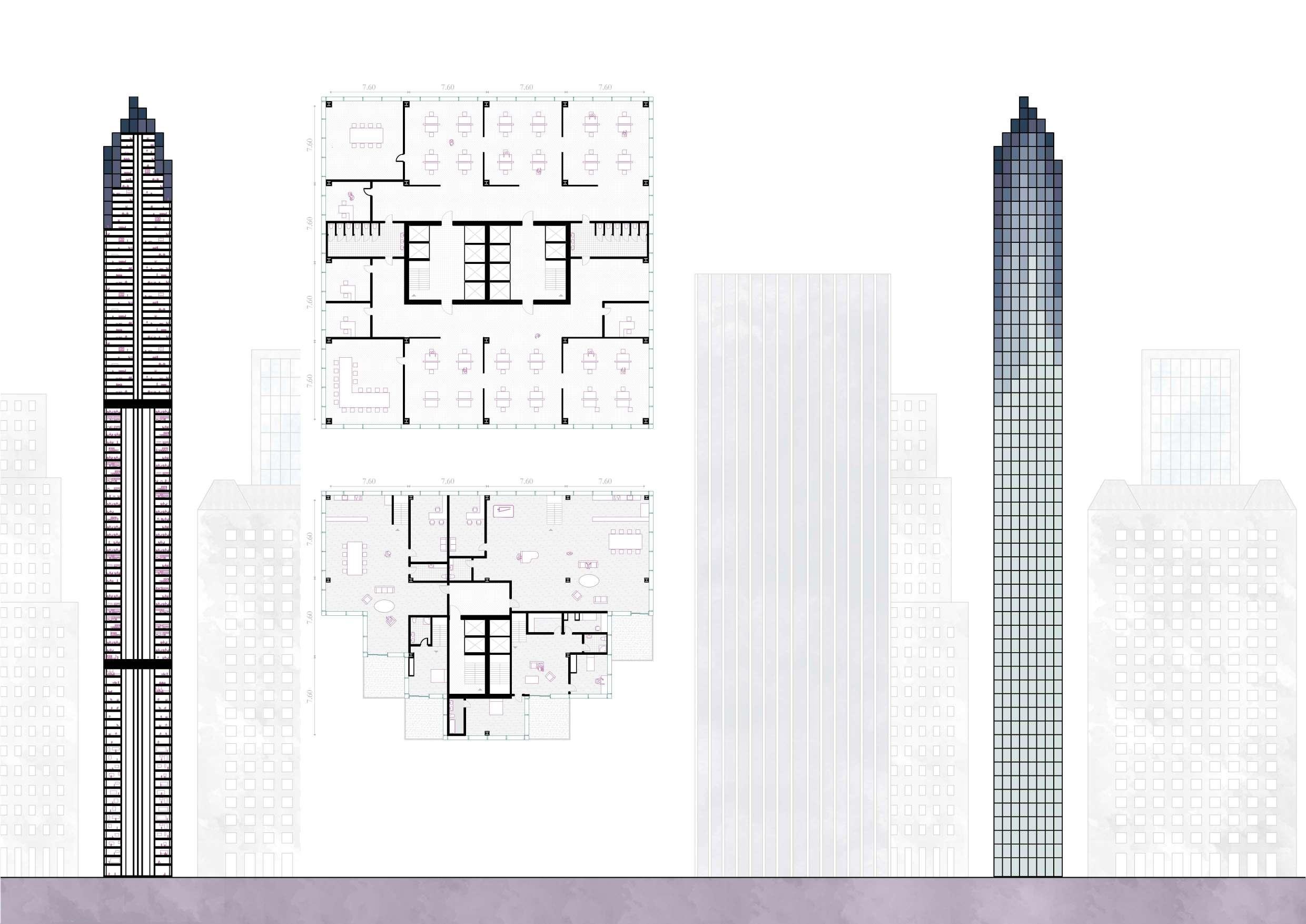
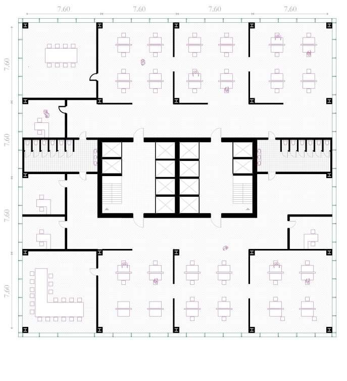
Multi-functional skyscraper
PROJECT 3: 2016-2017, 2nd semester
PROFESSOR: CAMPO BAEZA
LOCATION: NUEVA YORK, EEUU
DESCRIPTION
The project is generated with the idea of fading away into the sky through pixel subtraction. In this way, the tower visually disappears into the sky due to its great height, and physically through the subtraction that generates terraces facing Central Park, creating a more dynamic atmosphere compared to the area facing the city, which seeks to be flatter and more sober.

The tower hosts three different programmes:
• On the lower levels up to the first technical floor, a cultural programme houses a conservatory for musicians and dancers.
• The next floors up to the second technical floor are dedicated to office spaces.
• Finally, the upper floors contain a residential programme of duplex apartments, mostly intended for students and workers of the conservatory and offices. It is in these floors where the pixel subtraction occurs, creating a series of terraces with views towards the park.
The structure supporting the tower consists of HEB profile steel columns embedded in concrete, along with a central concrete core. The steel structure is connected to the floor slabs using a composite floor system with IPE 360 beams.