Analysis of Structures Under Different Seismic Zones
ANALYSIS OF STRUCTURES UNDER DIFFERENT SEISMIC ZONES
MAJOR PROJECT REPORT
Submitted in partial fulfillment of the requirements for the award of the degree of
Bachelor of Technology in Civil Engineering
Submitted to
Dr. A.P.J. Abdul Kalam Technical University, Uttar Pradesh, Lucknow
Submitted by
Akeel Javid
1900320009001
Km Swati Chauhan 1900320009005
Vanshaj Agarwal 1900320009010
Vijay Verma
1900320009011
Vikram Chauhan 1900320009012
Roma 1803200071
Under the supervision of Mr. Mohmmad Aslam (Asst. Professor)
Department of Civil Engineering
ABES Engineering College, Ghaziabad
May 2021 – 22
ABES ENGINEERING COLLEGE, GHAZIABAD
DEPARTMENT OF CIVIL ENGINEERING
CERTIFICATE
This is to certify that the work embodied in this project report entitled, “ANALYSIS OF STRUCTURES UNDER DIFFERENT SEISMIC ZONES” is being submitted by Akeel Javid (1900320009001), Km. Swati Chauhan(1900320009005), Vanshaj Agarwal (1900320009010), Vijay Verma (1900320009011), Vikram Chauhan (1900320009012) and Roma (1803200071) for partial fulfillment of the requirement for the award of Bachelor of Technology in Civil Engineering to “Dr A.P.J. Abdul Kalam Technical University, Uttar Pradesh, Lucknow” during the academic year 2021 – 22 is a record of a bonafide piece of work carried out by him under my supervision and guidance in the “Department of Civil Engineering”, A.B.E.S Engineering College, Ghaziabad.
HOD
Mr. Mohmmad Aslam (Civil) (Guide)
ABES ENGINEERING COLLEGE, GHAZIABAD
DEPARTMENT OF CIVIL ENGINEERING
ACKNOWLEDGEMENT
We express our deep sense of gratitude to our guide Mr. Mohmmad Aslam, ABES Engineering College, Ghaziabad (U.P.) whose kindness valuable guidance, and timely help encouraged us to complete this work. We consider ourselves privileged, who always shared vast experience so generously and patiently despite a busy schedule.
Special thanks to Mr. Amit Bajaj HOD CE, ABES Engineering College, Ghaziabad, (U.P.) for allowing me to pursue my studies for the present work and helping me in completing the project work.
We express our thanks to the authors whose works have been consulted by us during the project work and we would also thank our faculty members and technical staff without whom this project work would have been a distant reality.
We wish to thank our parents for their undivided support and interest who inspired and encouraged us to go our own way, without whom we would be unable to complete our project work. Last but not least we want to thank our colleagues who appreciated us for our work and motivated us and finally to almighty God who made all the things possible.
Akeel Javid (1900320009001)
Km Swati Chauhan (1900320009005)
Vanshaj Agarwal (1900320009010)
Vijay Verma (1900320009011)
Vikram Chauhan (1900320009012) Roma (1803200071)
ABES ENGINEERING COLLEGE, GHAZIABAD
DEPARTMENT OF CIVIL ENGINEERING
DECLARATION
We students of Bachelor of Technology in Civil Engineering session, 2021 – 22, Department of Civil Engineering, ABES Engineering College, Ghaziabad, U.P., hereby declare that the project work entitled, “ANALYSIS OF STRUCTURES UNDER DIFFERENT SEISMIC ZONES” submitted for partial fulfillment of the award of the degree of Bachelor of Technology is the outcome of my work, bonafide and authentic to the best of our knowledge and this work has been carried out taking care of all Engineering ethics. The work presented does not infringe any patented work and has not been submitted to any other university or anywhere else for the award of any degree or diploma course.
Akeel Javid (1900320009001)
Km Swati Chauhan (1900320009005)
Vanshaj Agarwal (1900320009010)
Vijay Verma (1900320009011)
Vikram Chauhan (1900320009012) Roma (1803200071)
ABES ENGINEERING COLLEGE, GHAZIABAD
DEPARTMENT OF CIVIL ENGINEERING
CERTIFICATE OF APPROVAL
The project work entitled “ANALYSIS OF STRUCTURES UNDER DIFFERENT SEISMIC ZONES” was submitted by Akeel Javid (1900320009001), Km. Swati Chauhan (1900320009005), Vanshaj Agarwal (1900320009010), Vijay Verma (1900320009011), Vikram Chauhan (1900320009012), and Roma (1803200071) has been examined by us and is hereby approved for the degree of “Bachelor of Technology in Civil Engineering” for which it has been submitted. It is understood that by this approval the undersigned does not necessarily endorse or approve any statement made, opinion expressed, or conclusion drawn therein, but approved the project work only for the purpose for which it has been submitted.
HOD Mr. Mohmmad Aslam
Date:
Date:
ABSTRACT
The study and design of reinforced cement concrete (RCC) buildings are done both manually and by utilizing software in structural engineering. Using the structural engineering program STAAD.Pro V8i, we studied and constructed RCC (G+5) buildings, both regular and irregular. Because of the discontinuity in stiffness or the geometry of the structure, the challenge in the design of the irregular building arises. The load combinations were designed using StaadPro.v8i following IS 1893-2016. To compare the regular and irregular buildings, the center of mass, the center of stiffness, torsion, and base shear developed were determined. The regularity in plan, mass, and stiffness may be disturbed in recent years as a result of the necessity for a unique architectural appearance of the building, which may lead to the development of torsion in the structure. The project entails a comparison of regular and irregular buildings of the same area and mass in different seismic zones, with the irregularity generated by a movement in the center of stiffness. In this study we have given a comparative change (analysis) in all parameters of buildings like base shear, node displacement, frequency and over all stiffness in different zones and different soils.
CHAPTER 1
INTRODUCTION
Due to absolute regularity is an idealization that rarely occurs in fact, we see that real structures are usually erratic. In the case of buildings, major seismic codes across the world distinguish between abnormalities in plan and irregularities in elevation for practical purposes, although it must be understood that irregularities in the structure are the result of a combination of both sorts. During prior earthquakes, unusual structural configurations, either in the plan or in elevation, were frequently identified as one of the key reasons for failure.
1.1. REGULAR AND IRREGULAR STRUCTURE
The symmetrical and compact shape of the building is referred to as the structure's regularity. The objective of building regularity is to minimize unpredictably highstress concentrations that might lead to local collapses and changes in dynamic behavior. Irregular structures are mainly three types as stiffness irregular structure, mass irregular structure, geometrically irregular structure. that can be described as "irregular" using both perceptive criteria and irregularity norms supplied by guidelines, show that the irregularity is "visible" if the diaphragms are rigid and the columns are distributed according to the shape. The irregularity causes torsional effects in the response, which can be accounted for at the design stage. A thorough review of the literature is conducted to comprehend the concept of regularities and irregularities in construction. In addition, literature on shear walls, irregularities in buildings, and torsion in buildings is reviewed, and the behavior of the structure is comprehended.
1.2 STAAD.Pro
STAAD.Pro is a program for structural analysis and design. It has a cutting-edge user interface, visualization features, and international design standards. It's used to create
3D models, analyze them, and create multi-material designs. Several steels, concrete, and timber design codes are supported in the commercial edition of STAAD.Pro. It is one of the software tools designed to assist structural engineers in automating their jobs and eliminating the time-consuming and inefficient procedures associated with manual approaches.
STAAD.Pro was created in Yorba Linda, California by Research Engineers International. Bentley Systems purchased Research Engineer International in late 2005. STAAD Pro is a structural analysis and design program that is commonly used to evaluate and design bridges, towers, buildings, transit, industrial, and utility structures. STAAD.Pro V8i is the most recent version of the software, featuring new and improved functionality. Any engineering structure can now be analyzed and designed with the STAAD.Pro V8i.
1.3 SEISMIC ACTIVITY
An earthquake is a natural or manmade occurrence that can occur at any moment and in any location. As a result, structures must be constructed in such a way that they are safe in the event of a disaster. The IS: 1893 Code of Practice For "CRITERIA FOR EARTHQUAKE RESISTANT DESIGN OF STRUCTURES" provides recommendations for structural design. This was changed in 2002 to account for the effects of multiple earthquakes that happened after the code was last amended in 1984. The nature of the foundation soil; material, form, scale, and style of construction; and the duration and features of ground motion all influence how a structure responds to an earthquake. This response is determined by the structure's absorbing character (damping) and natural period of vibration. The amplitude of vibrations builds up in a few cycles during an earthquake.
1.4 SEISMIC ZONES
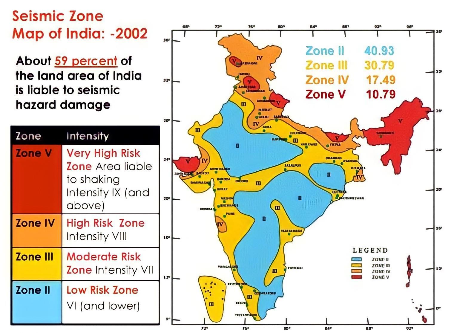
Based on scientific inputs relating to seismicity, historical earthquakes, and the tectonic structure of the region, the Indian subcontinent is split into four seismic zones (II, III, IV, and V). Previously, earthquake zones were split into five severity zones,
however, the Bureau of Indian Standards [IS 1893 (Part I):2002] categorized the country into four seismic zones, with the first and second seismic zones merged.
The official agency for releasing seismic hazard maps and codes is the Bureau of Indian Standards. It has published several seismic zoning maps, including a six-zone map in 1962, a seven-zone map in 1966, and a five-zone map from 1970 to 1984.
Figure 1.1: Seismic Zone Map of India: 2002
CHAPTER 2
PROJECT WORK
2.1 OBJECTIVE
The majority of constructions in the modern age are defined by irregularity in both their designs and vertical configurations. During an earthquake, the damage to the structure usually begins in the region of the building system's structural vulnerability. Damages or losses are higher in structures with irregular alternatives than in buildings with regular options. As a result, to accept the behavior produced by the disastrous earthquake, irregular construction would require rigorous structural research. It will be interesting to investigate the stability of buildings with various geometries and how they react to seismic and other forces. As a result, our goal is to:
• It is to compare regular and irregular buildings based on seismic force.
• To test the seismic resistance of a building in STAAD.Pro.
• To compare the performance of structures with varied plan dimensions in different seismic zones and soil types in different seismic zones and soil types.
• To use STAAD.Pro to design an earthquake-resistant multi-storey building.
• To compare the relative storey drift of the models.
Modulus of elasticity of brick masonry: 14100 N/mm2
Poison’s ratio of brick masonry: 0.2
Damping ratio: 5%
2.3 PLAN AND DIMENSIONS OF MODELS
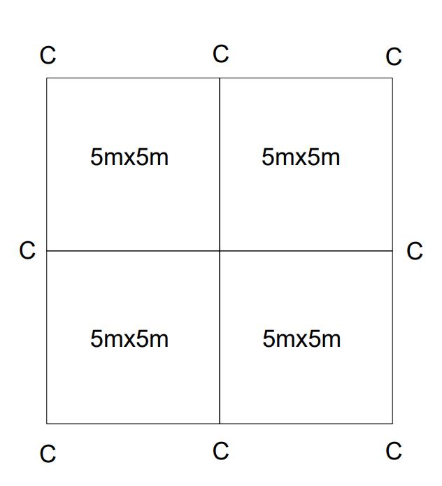
In this project we have taken two types of structures viz. regular and irregular structures. The plan of the regular structure is square that has been partitioned into four equal parts for regularity. The plan of regular structure is shown in the figure 2.1 The dimensions of the plan of the regular structure are:
Figure 2.1: Plan of Regular Structure
1. Built-up area = 100 m2
2. No of columns = 9
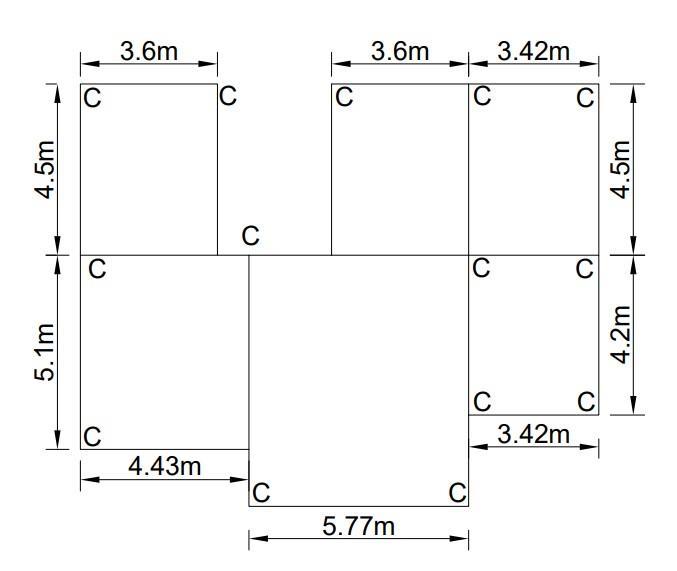
The plan of the irregular structure is show in the figure 2.2. The dimensions of the plan of the irregular structure area:
1. Built-up area = 112.87 m2
2. No of columns = 14
2.4 Seismic Calculations
Table 1: Seismic Calculations
Figure 2.2: Plan of Irregular Structure
2.5 REGULAR STRUCTURE LOADINGS
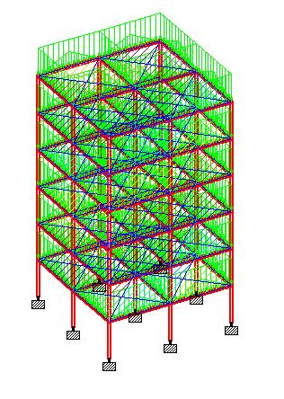
Figure 2.3: Self-Weight
Figure 2.4: Floor Load (3.04 kN/m2)
Figure 2.5: Wall Load (13.8 kN/m2)
2.6: Live Load on each floor except roof (2 kN/m2)
2.7: Roof Load (1.5 kN/m2)
Figure
Figure
Figure 2.8: 1.5x(Dead Load + Live Load)
Figure 2.9: 1.2x(Dead Load+Live Load)
Figure 2.10: 1x(Dead Load+Live Load)
2.6 IRREGULAR STRUCTURE LOADING
Figure 2.11: Self-Weight
Figure 2.12: Floor Load(3.04 kN/m2)
Figure 2.13: Wall Load(13.8 kN/m2)
2.14: Live Load on each floor except roof (2 kN/m2)
2.15: Roof Load (1.5 kN/m2)
Figure
Figure
2.16: 1.5x(Dead Load + Live Load)
2.17: 1.2x(Dead Load + Live Load)
2.18: 1x(Dead Load + Live Load)
Figure
Figure
Figure
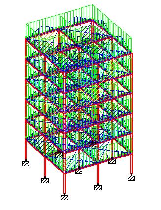
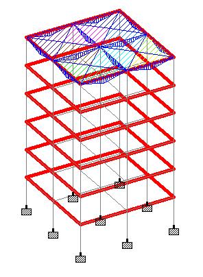
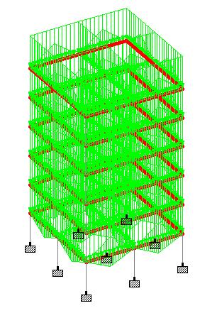
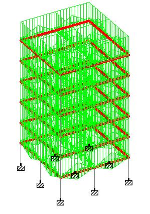
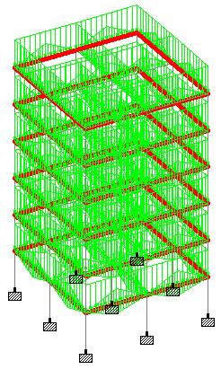
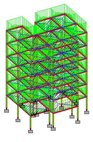
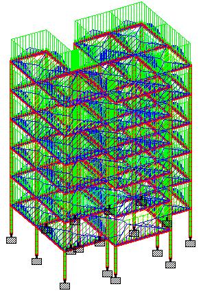
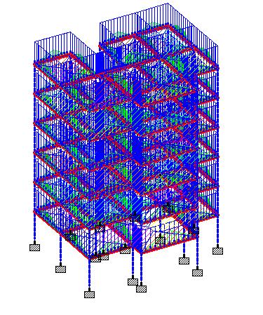
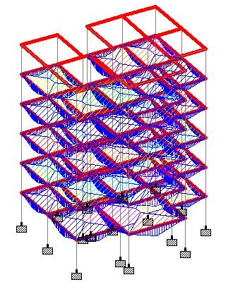
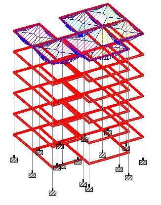
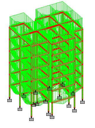
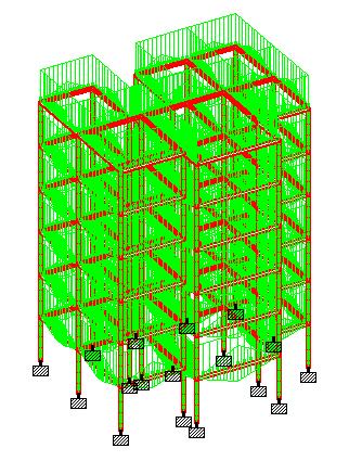
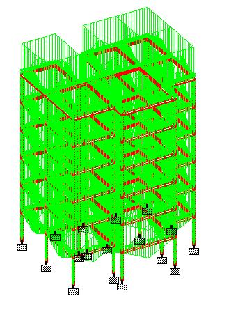
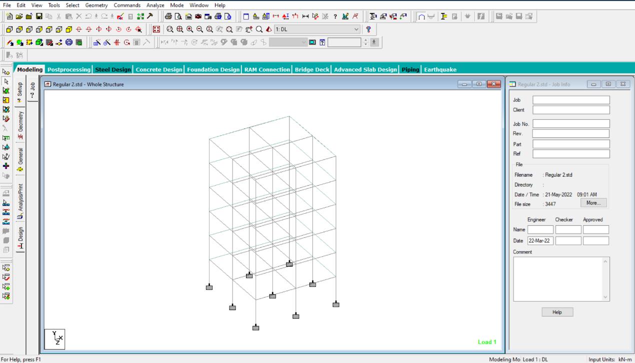
2.7 STAAD.Pro Illustrations
2.20: Nodes and Material Defining in STAAD.Pro
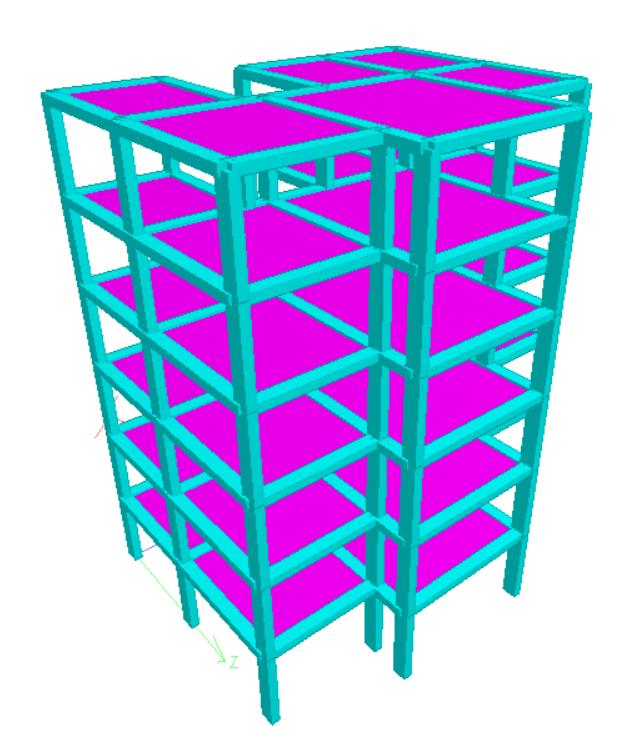
Figure 2.19: G+6 Building Modelling
Figure
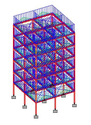
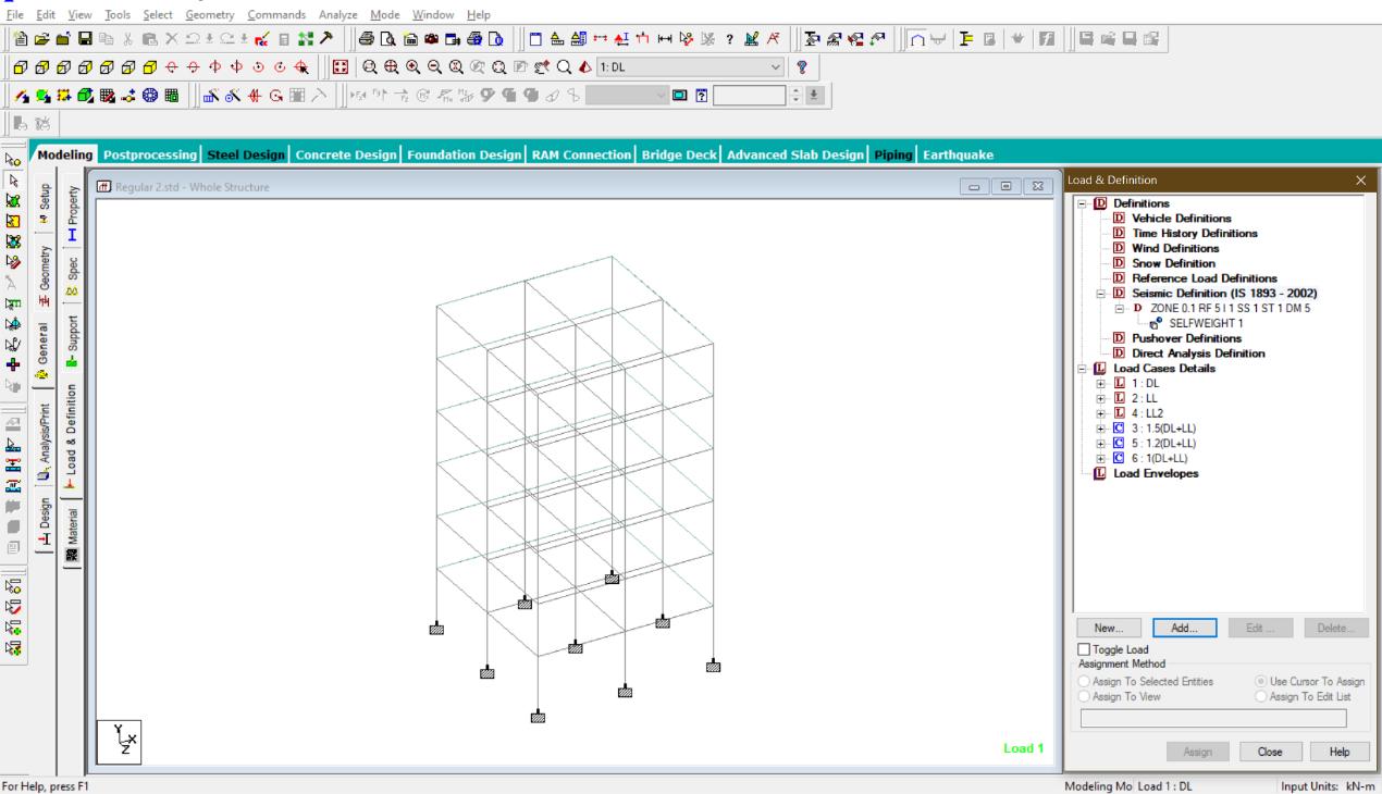
2.21: Defining and Assigning Loads in STAAD
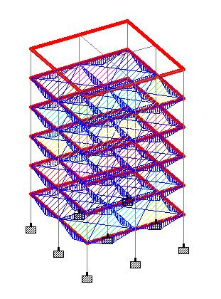
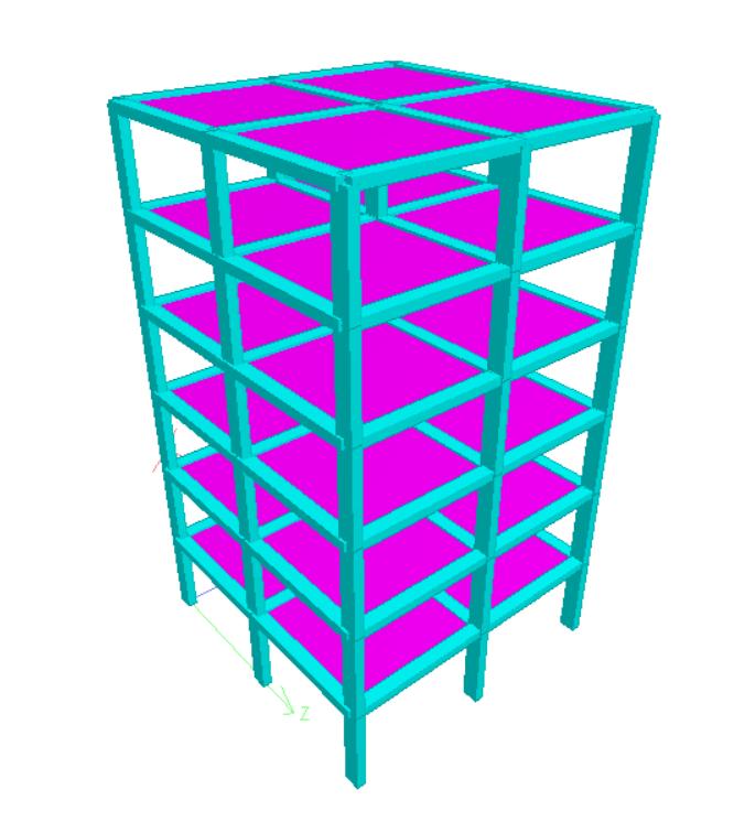
2.22:
Figure
Figure
3-D View of Regular and Irregular Models
CHAPTER 3
LITERATURE REVIEW
The overall goals of this chapter are to first depict the work done by various researchers in terms of analyzing the behavior of regular and irregular structures to the effects of seismic forces, analyzing different models of regular and irregular buildings on various seismic zones, and finally providing the construction world with an optimal solution.
EFFECTS OF SEISMIC FORCES ON
OVER VARIOUS SEISMIC ZONES:
STRUCTURES BUILT
1. Pr. T. Jayakrishna (2018) looked at all of the parameters, including base shear, node displacement, average frequency, and overall stiffness, and found that Seismic Zone 5 is more vulnerable than the other zones for all types of structures and that the base shear is nearly the same for regular and irregular structures. Regular structures, he claims, have the greatest displacement, whereas irregular structures have the least. They also discovered that irregular structures have less lateral displacement.
2. Naveen G.M and Ghaya studied all of these characteristics briefly, including frequency, drift, displacement, and base shear (2021). Zone 5 encompasses the area’s most vulnerable to earthquakes with a magnitude of MSK IX or higher. Effective (zero period) level earthquakes are indicated by a zone factor of 0.36 (the highest horizontal acceleration that a structure can endure). The reaction of regular and irregular building structures to plan irregularities located in seismic zone V was investigated in this work, and Model 3 (T-shaped) had a higher frequency value than irregularly shaped buildings. Drift is greater in the structure's center. Drift is greatest in a regular-shaped building. The number of stories increases the displacement. I also discovered that model 2 has the most displacement (rectangular).
3. Akhil (P.G) and Pr. Aswathy S. Kumar: The effects of numerous irregularities on the seismic response of a structure were researched, as were the stiffness, base shear, frequency, and node displacement parameters. In this literature review, he discussed how the largest base shear is obtained in a regular construction and how the displacement is the smallest in an irregular structure. In irregular structures, the average frequency is the highest, and U-shaped vertical irregular buildings have higher displacement than other buildings. Based on the findings of the research, this study discovered that buildings with regular and irregular designs give an analytical technique for seismic zones.
4. Ravi Kiran (MTech.) and Pr. Sridhar R (2016) used three models to evaluate structure stiffness: regular structure, planned irregular structure, and vertical irregular structure. For Zones II, III, IV, and V, all three models are analyzed using static and dynamic seismic loading. The data is tabulated, and graphs for displacement, drift, base shear, and period are plotted. Based on the results and discussion, the structural behavior and stiffness of regular and irregular constructions are concluded. Regular structures, in both static and dynamic analysis, show the greatest displacement and drift across all zones.
5. Barkha Verma (MTech) and Pr. Anurag Wahani (2016) using the latest software package, STAAD Pro, assessed and compared the seismic response of the G+9-storey RCC frame structure with varied soil conditions (hard, medium, and soft soil) for seismic Zone V. Except for the soil type, Models M1, M2, and M3 have the same structural and seismic properties. The Equivalent Static method of seismic analysis is used to analyze all three models in STAAD.Pro V8i software. The model's response is measured in terms of maximum storey displacement, column compressive stress, and the amount of steel required. The study's goal is to test the three models' stability in a variety of soil types and situations.
6. Pr. Amit Joshi and Pr. Murtaza (AIT Bhopal 2018) investigated the seismic analysis of multi-storey buildings with footing columns, as well as the analysis of buildings with footing columns located on different types of soil and seismic
zones. Comparison of P + 3 and P + 30 footing column buildings with and without footings. Storey Drift and Base Shear were the parameters of this literature review. A brief explanation of this literature review is that the storey drift is high in buildings with footing columns, and the storey drift and base shear are greater in soft soil. The base shear is nearly the same in P+3 with or without a footing column, and the base shear and storey drift are greater in seismic zone 5 than in seismic zone 3 in multistorey buildings with floating columns.
7. Pr. P. A. Krishnan and N. Thasleen (P.G) (NIT, Tamil Nadu 2020) researched the seismic analysis of irregular RC building frames as well as the parameters of re-entrant pushover analysis and strengthening approaches. A total of ten reentrant corner models were investigated. The major parameters of this literature study and a brief explanation are that the storey displacement increases as the number of water increases. The stated projection as well as the high level of stress There is a concentration at the re-entrant corners. The stress concentration of reentrant corner models and the percentage change in top-storey displacement, in addition, L-shaped models have a very high floor displacement but a smaller stress concentration. This is a blueprint for RC building frames that aren't straight.
8. Aman Dussawar (UG) Varun Bagade (UG) Syed Faraz Ali (UG) (NIT, Nagpur) Jacky Gurnani, Ph.D. (2021) Using both methods of seismic analysis, we examined the entire structures using STAAD Pro (V8i) software to access parameters such as support reactions, shear forces, axial force, bending moment, base shear, seismic forces, and displacement for two different seismic zones (zone II and IV) regular (rectangular or square) structural configurations: High-rise (G+10) multistoried building structures: static (Equivalent Lateral) and dynamic (Response Spectrum Method).
CHAPTER 4
METHODOLOGY ADOPOTED
4.1 Modeling
For the consideration of the type of structure, modeling has been done using STAAD.Pro.
4.2 Generation of Nodal Point
As per the planning concerning the positioning of a column in a building, their respective nodal point has been created on that model.
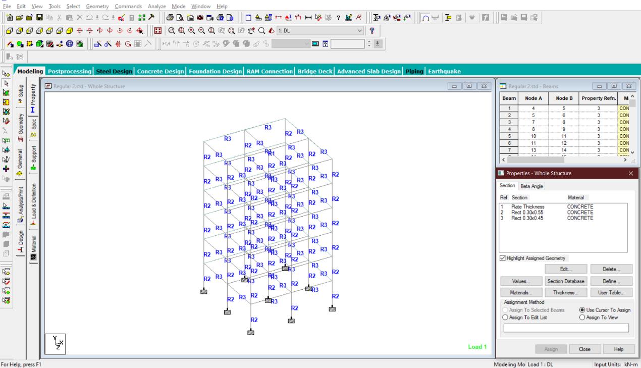
4.3 Property Definition
Using General-Property command define the property as per size requirement to the respective building on STAAD.Pro. So, beam and columns have been generated after assigning to selected beam and columns.
4.4 Create and Assign Support &Member Property
After column definition at supports have been provided as fixed below each column by selecting columns using Node Curser and its cross-section assigning based on load calculations and property definition.
4.5 3-D Rendering
After assigning the member property to the structure the 3-D view of the structure can be shown using the 3-D Rendering command.
4.6 Load Assignment
Dead load: The dead load contains the weight of walls, partitions floor finishes, false
ceilings, floors, and the other permanent standing construction in the buildings. The dead load loads are estimated from the dimensions of various members of a building and their unit weights.
• The unit weights of plain concrete and reinforced concrete is taken as 25kN/m3
• The unit weight of masonry taken as 19kN/m3
• As per IS:1893 (Part 1)-2016, the dead load has been assigned based on member load, floor load, self-weight of the beam’s definition.
Live Load: As per IS:875 (part 2)-1987, live load 2kN/m has been assigned to the members.
Seismic Load: After defining the seismic load as per the requirement of IS: 1893 (Part 1): 2016, the seismic load has been assigned concerning +X, -X, +Z, and –Z directions with their respective appropriate seismic factor.
Load combination: Required load combinations cases for seismic analysis have been assigned to the model based on specified loading combinations provided in the Indian standard CODES that are also available in STADD-Pro.
4.7 Structural Analysis On STAAD.Pro
After adding Analysis/Print, using Run Analysis Command, the structure is analyzed and a detailed study of forces and bending moment is undertaken through the postprocessing mode to recognize their shear forces, bending moment diagrams to check is safe or not.
4.8 Design of Structure On STAAD.Pro
The design is undertaken as per IS 456:2000 for RCC. M25 concrete and Fe415 are used as design parameters. Percentage steel of 3% has been specified as per IS Code standards and the design parameters have been assigned to respective each beam and column to get the final design.
4.9 Output Generation
After that output file is generated which contains the structural design of each beam and column member of a structure
CHAPTER 5
RESULTS AND DISCUSSION
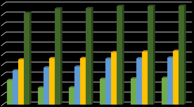
5.1 RESULTS OF STOREY DRIFT
The drift of one level of a multi-storey building relative to the level below is referred to as storey drift. The difference between the roof and floor displacements of any given storey as the building sways during an earthquake, normalized by the storey height, is referred to as inter storey drift.
Table 2: Storey Drift for Regular Structure in Hard Soil
Table 3: Storey Drift for Regular Structure in Medium Soil
Table 4: Storey Drift for Regular Structure in Soft Soil
Table 5: Storey Drift for Irregular Structure in Hard Soil
Table 6: Storey Drift for Irregular Structure in Medium Soil
Figure: Comparison chart of
CONCLUSION
After analyzing and comparing we can get following conclusions:
• Storey displacements gradually increase on every floor in a G+6 regular building located at Zone II and Zone III in all three soils.
• Storey displacements gradually increase on every floor in a G+6 irregular building located at Zone II and Zone III in all three soils but the displacement is higher as compared to a regular building.
• In Zone IV and Zone V the storey displacement increases with each storey but has a sharp decline in the rate of storey displacement on the top floor of the building in both regular and irregular buildings.
• The storey drift in a irregular building is more as compared to a regular building ini any given seismic zone and soil type.
• The rate of storey drift accends from hard soil to medium soil to soft soil. Hence, buildings in soft soil have higher storey drift as compared to other soils.
• The storey drift of regular building in Zone II exceptionally has a decending rate of drift from hard to soft soil.
• Zone V has highest rate of storey drift in any given soil for both types of buildings.
REFERENCES
1. Akhil R and Prof. Aswathy S Kumar (2017), “SeismicAnalysis of Regular and Irregular Buildings with Vertical Irregularity using STAAD.Pro”ISSN: 2395 –0056.
2. Prof. T. Jayakrishna, K. Murali HOD, Powar Satish, J Seetunya (2018), “Seismic Analysis of Regular and Irregular Multi-Storey Buildings by using STAAD.Pro”ISSN: 0976 – 6308.
3. Prof. P A Krishnan and N Thasleen (2020), “Seismic Analysis of Plan Irregular RC Building Frames”doi:10.1088/1755 – 1315/491/1012021.
4. Prof. Naveen G. M and Prof. Chaya. S (2021), “Study on Regular and Irregular Building Structures during an Earthquake” ISSN: 2455 – 7137.
5. Ravi Kiran and Prof. Sridhar. R (2016), “Comparative Study of Regular and Vertically Irregular Building under Seismic Loading”ISSN: 2319 – 1163.
6. Barkha Verma and Prof. Anurag Wahane (2016), “Effect of Different Soil Conditions on Seismic Response of multi-storey Irregular Model using STAAD.Pro V8i” ISSN; 2395 – 0056.
7. Prof. Jacky Gurnani, Aman Dussawar, Varun Bagade, and Syed Faraz Ali (2021), “To Analyze and Study the Behaviour of multi-storey Building in Different Zones of India – ISSN: 2320 – 2882.
8. Amit Joshi and Murtaza Safdari (2018), “A Review: Seismic Analysis of multistorey Building having Floating Columns” ISSN: 2349 – 5197.