AINSLEY
MCMASTER | Selected Works

MCMASTER | Selected Works
After a career break I joined BuroMilan Facade, a facade consulting firm established Spring 2024 in partnership with BuroMilan, a structural consulting firm based out of Milan, Italy. Project work primarily focused on coordination with facade contractors. Work ranged from assisting in the creation to tender packages with quantity take-offs, preliminary system details to developing shop drawings for construction.
Prior to working with BuroMilan Facade, I spent five years based in London to help open Front Inc›s UK office and work on a number of international projects ranging in program and scale. Most recently, led a team through Design Assist for a tower in Vancouver, Canada in collaboration with the facade contractor, client, and architects to develop facade systems for, when constructed, the tallest Passive House project ever built. Before moving to London, I worked in New York City at Front Inc. for three years on a number of local and national projects with widely ranging levels of facade complexity, system design, and performance requirements.
To the right is a list of projects I worked on during my time at both companies. Marked with dashes are the projects which have been expanded on in the following pages.
VA | Design in Atlanta, GA
Collaborator | 2014-2015
MALL in Atlanta, GA
Collaborator | 2014-2015
Georgia Institute of Technology | School of Architecture
Research Assistant | 2013-2015 Teaching Assistant | 2015
Georgia Institute of Technology | School of Architecture
Graduate Studio Review | Fall 2015, Spring 2017, Spring 2020
Coventry University | School of Architecture
Studio Review | Spring 2020, Spring 2021, Fall 2021, Spring 2022
Guest Lecturer Fall 2020, Fall 2021, Fall 2022
Trojena with WeBuild | Neom, Saudi Arabia | 2024
Tiffany with Tensoforma | Toronto, Canada | 2024
Tiffany with Tensoforma | Taipei City, Taiwan | 2024
Tiffany Institutional Concept Book with Tiffany | 2024
1075 Nelson with WKK Architects | Vancouver, Canada | 2023
Bulgari Tower with ACPV | Dubai, UAE | 2022
MDP with RPBW | Milan, Italy | 2022
Milano Campus Nord with RPBW | Milan, Italy | 2022
Gulf of Aqaba Mansions with Steven Chilton Architects | 2022
ISMETT 2 with RPBW Palermo, Italy | 2021
109 Brookline with Gensler | Boston, MA | 2021, Under Construction
Taikoo Ceiling with Tiller Studio | Hong Kong | 2021
Volvo Showroom with SO-IL | Seoul, Korea | 2021, Completed
Colechurch House with Foster + Partners London, UK | 2020
Tselinnyi Cultural Centre with Asif Khan | Almaty, Kazakhstan | 2020
Taichung Green Museumbrary with SANAA | Taiwan | 2020, Under Construction
Dior with Aranda/Lasch | Doha, Qatar | 2019, Completed
Phnom Penh Int’l Airport with Foster + Partners | Phnom Penh, Cambodia | 2019, Under Construction
Lusail Towers with Foster + Partners | Lusail, Qatar | 2018, Completed
Longwood Gardens with Weiss/Manfredi Kennett Square, PA | 2018, Under Construction
30 Warren with Post-Office Architectes | New York, NY | 2018, Completed
712 Fifth Ave with KPF | New York, NY | 2018, Completed
1100 Sixth Ave with MdeAS Architects | New York, NY | 2018, Under Construction
S. Pellegrine Flagship Factory with BIG | New York, NY | 2018, Under Construction
Pendry Hotel with SOM | New York, NY | 2017, Completed
Yale CIT with Weiss/Manfredi | New Haven, CT | 2017, Completed
Perth+ with REX | Perth, Australia | 2017
Confidential Tower | Dubai, UAE | 2017
GD Office Building with LSM | Falls Church, VA | 2017, Completed
262 Fifth Ave with Meganom | New York, NY | 2016 Under Construction
Collegiate Tower with BIG | New York, NY | 2016 Under Construction
Lloyd Harbor Residence with REX | Long Island, NY | 2016 Under Construction
Georgia Tech HPC Center with John Portman & Associates | Atlanta, GA | 2016, Completed
Spence School with Rogers Partners | New York, NY | 2016, Completed
1 John Street with Alloy | New York, NY | 2015, Completed
Victoria’s Secret Lippo Plaza with O’Neil Langan Architects | Shanghai, China | 2015, Completed
Victoria’s Secret 5th Ave with O’Neil Langan Architects | New York, NY | 2015, Completed
Google Campus with BIG / Heatherwick Studio | Mountain View, CA | 2015

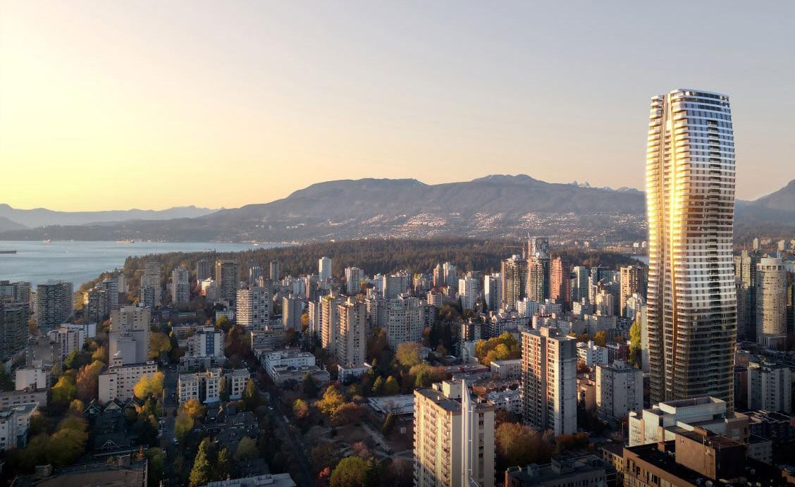
Location: Vancouver, Canada
Architect: WKK Architects
Role: Senior Associate
Scope: Design Assist
Responsibilities included:
- Project management (internal and external)
- Coordination with Architects, Client, Executive Architects and related consultants
- System detailing and development in 2D (AutoCAD) and 3D (Rhino3D)
- Thermal analysis to EN standards on the basis of achieving Passivhaus Certification
- Material and system research
- Shop drawing review
Project systems included terraces and megapanel units. Because the two facade systems are traditionally loaded differently (base and top, respectively), studies to minimise differential movement was key to ensure an air-tight system that met the Passive House requirements. As a preliminary study, the stack joint for the megapanel was evaluated in a series of details to discuss with the design team. Ultimately, Option 3 was selected.
APPROVED OPTION
System Design | Stack Joint Studies


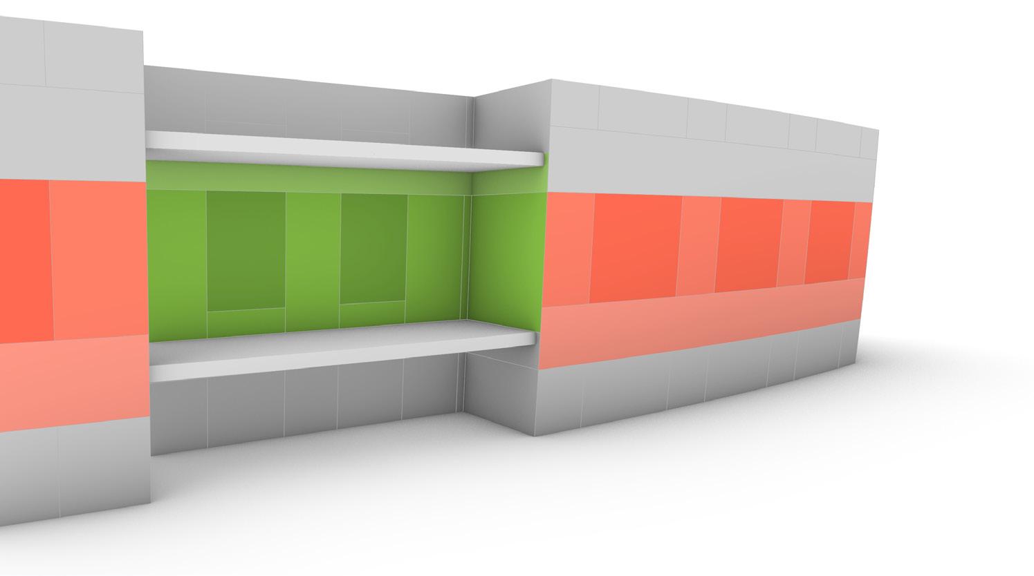

• Megapanel is hung from the top of slab similar to a unitized system
• Megapanel is hung from the top of slab similar to a unitized system
• Transition between megapanels and infill panels at the balconies require consideration for differential movements
• Transition between megapanels and infill panels at the balconies require consideration for differential movements
• Megapanel is hung from the top of slab similar to a unitized system
• Megapanel is hung from the top of slab similar to a unitized system
• Stack joint requires custom solution of Wicona's passivhaus-certified system (separately, customization of standard window system required to accommodate slope at all locations)
• Stack joint requires custom solution of Wicona's passivhaus-certified system (separately, customization of standard window system required to accommodate slope at all locations)
• Transition between megapanels and infill panels at the balconies require consideration for differential movements
• Transition between megapanels and infill panels at the balconies require consideration for differential movements
• The horizontal spandrel is supported directly back to megapanel frame without additional cantilevering
• The horizontal spandrel is supported directly back to megapanel frame without additional cantilevering
• *Stack joint follows glass line
• *Stack joint follows glass line
Megapanel is hung from the top of slab similar to a unitized system
• Megapanel is hung from the top of slab similar to a unitized system
Transition between megapanels and infill panels at the balconies require consideration for differential movements
• Transition between megapanels and infill panels at the balconies require consideration for differential movements
Megapanel is hung from the top of slab similar to a unitized system
• Megapanel is hung from the top of slab similar to a unitized system
• Megapanel is base-supported from the top of slab which introduces installation complexities
• Megapanel is base-supported from the top of slab which introduces installation complexities
• Megapanels and infill panels at each level are supported off the same slab, allowing for simpler transition between systems
• Megapanels and infill panels at each level are supported off the same slab, allowing for simpler transition between systems
Transition between megapanels and infill panels at the balconies require consideration for differential movements
• Stack joint a custom extrusion that is divorced from the window system and requires no customization of Wicona's passivhaus-certified system (separately, customization of standard window system required to accommodate slope at all locations)
• Transition between megapanels and infill panels at the balconies require consideration for differential movements
Stack joint is a custom extrusion that is divorced from the window system and requires no customization of Wicona's passivhaus-certified system (separately, customization of standard window system required to accommodate slope at all locations)
• Megapanel is base-supported from the top of slab which introduces installation complexities
• Megapanel is base-supported from the top of slab which introduces installation complexities
• Megapanel is hung from the top of slab similar to a unitized system
• Megapanel is hung from the top of slab similar to a unitized system
• Stack joint requires custom solution of Wicona's passivhaus-certified system (separately, customization of standard window system required to accommodate slope at all locations)
• Stack joint requires custom solution of Wicona's passivhaus-certified system (separately, customization of standard window system required to accommodate slope at all locations)
• Megapanel is hung from the top of slab similar to a unitized system
Megapanel is hung from the top of slab similar to a unitized system
• The stack joint sits proud of insulation which may impact thermal performance
• The stack joint sits proud of insulation which may impact thermal performance
• The horizontal spandrel is supported directly back to megapanel frame without additional cantilevering
• Transition between megapanels and infill panels at the balconies require consideration for differential movements
• Transition between megapanels and infill panels at the balconies require consideration for differential movements
• The horizontal spandrel is supported directly back to megapanel frame without additional cantilevering
• *Stack joint follows glass line
• *Stack joint follows glass line
• The stack joint sits proud of insulation which may impact thermal performance
• The stack joint sits proud of insulation which may impact thermal performance
• Stack joint requires custom solution of Wicona's passivhaus-certified system (separately, customization of standard window system required to accommodate slope at all locations)
• Stack joint requires custom solution of Wicona's passivhaus-certified system (separately, customization of standard window system required to accommodate slope at all locations)
• The horizontal spandrel is supported directly back to megapanel frame without additional cantilevering
• The horizontal spandrel is supported directly back to megapanel frame without additional cantilevering
• *Stack joint follows glass line
• *Stack joint follows glass line
• The stack joint sits proud of insulation which may impact thermal performance
• The stack joint sits proud of insulation which may impact thermal performance
• The horizontal spandrel cantilevers vertically and will introduce installation complexities
• *Stack joint follows megapanel frame's line
*Stack joint follows megapanel frame's line
Stack joint is a custom extrusion that is divorced from the window system and requires no customization of Wicona's passivhaus-certified system (separately, customization of standard window system required to accommodate slope at all locations)
• Stack joint a custom extrusion that is divorced from the window system and requires no customization of Wicona's passivhaus-certified system (separately, customization of standard window system required to accommodate slope at all locations)
The horizontal spandrel cantilevers vertically and will introduce installation complexities
• Transition between megapanels and infill panels at the balconies require consideration for differential movements
The stack joint sits inboard of insulation which may improve thermal performance
• The stack joint sits inboard of insulation which may improve thermal performance
Transition between megapanels and infill panels at the balconies require consideration for differential movements
The horizontal spandrel cantilevers vertically and will introduce installation complexities
• The horizontal spandrel cantilevers vertically and will introduce installation complexities
*Stack joint follows megapanel frame's line
• *Stack joint follows megapanel frame's line
The stack joint sits inboard of insulation which may improve thermal performance
Stack joint is a custom extrusion that is divorced from the window system and requires no customization of Wicona's passivhaus-certified system (separately, customization of standard window system required to accommodate slope at all locations)
• Stack joint a custom extrusion that is divorced from the window system and requires no customization of Wicona's passivhaus-certified system (separately, customization of standard window system required to accommodate slope at all locations)
• The stack joint sits inboard of insulation which may improve thermal performance
The horizontal spandrel cantilevers vertically and will introduce installation complexities
• The horizontal spandrel cantilevers vertically and will introduce installation complexities
*Stack joint follows megapanel frame's line
• *Stack joint follows megapanel frame's line
The stack joint sits inboard of insulation which may improve thermal performance
• The stack joint sits inboard of insulation which may improve thermal performance
• Megapanels and infill panels at each level are supported off the same slab, allowing for simpler transition between systems
• Stack joint is a custom extrusion that is divorced from the window system and requires no customization of Wicona's passivhaus-certified system (separately, customization of standard window system required to accommodate slope at all locations)
• Stack joint is a custom extrusion that is divorced from the window system and requires no customization of Wicona's passivhaus-certified system (separately, customization of standard window system required to accommodate slope at all locations)
• Megapanels and infill panels at each level are supported off the same slab, allowing for simpler transition between systems
• Megapanel is base-supported from the top of slab which introduces installation complexities
• *Stack joint follows megapanel frame's line
• *Stack joint follows megapanel frame's line
• Stack joint is a custom extrusion that is divorced from the window system and requires no customization of Wicona's passivhaus-certified system (separately, customization of standard window system required to accommodate slope at all locations)
• The horizontal spandrel cantilevers vertically and will introduce installation complexities
• Megapanel is base-supported from the top of slab which introduces installation complexities
• The horizontal spandrel cantilevers vertically and will introduce installation complexities
• Stack joint is a custom extrusion that is divorced from the window system and requires no customization of Wicona's passivhaus-certified system (separately, customization of standard window system required to accommodate slope at all locations)
• The stack joint sits inboard of insulation which may improve thermal performance
• Megapanels and infill panels at each level are supported off the same slab, allowing for simpler transition between systems
• The stack joint sits inboard of insulation which may improve thermal performance
• Megapanels and infill panels at each level are supported off the same slab, allowing for simpler transition between systems
• The horizontal spandrel cantilevers vertically and will introduce installation complexities
• The horizontal spandrel cantilevers vertically and will introduce installation complexities
• *Stack joint follows megapanel frame's line
• *Stack joint follows megapanel frame's line
• The stack joint sits inboard of insulation which may improve thermal performance
• Stack joint is a custom extrusion that is divorced from the window system and requires no customization of Wicona's passivhaus-certified system (separately, customization of standard window system required to accommodate slope at all locations)
• The stack joint sits inboard of insulation which may improve thermal performance
• Stack joint is a custom extrusion that is divorced from the window system and requires no customization of Wicona's passivhaus-certified system (separately, customization of standard window system required to accommodate slope at all locations)
• The horizontal spandrel cantilevers vertically and will introduce installation complexities
• The horizontal spandrel cantilevers vertically and will introduce installation complexities
• *Stack joint follows megapanel frame's line
• *Stack joint follows megapanel frame's line
• The stack joint sits inboard of insulation which may improve thermal performance
• The stack joint sits inboard of insulation which may improve thermal performance
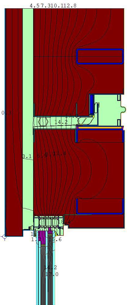
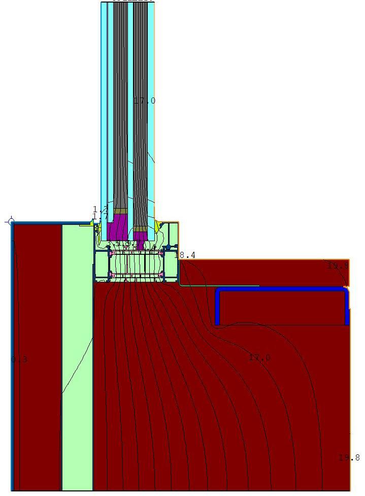
To vet the system design and expected thermal performance, preliminary thermal analysis was done across iterations of the system design and in consideration of the varaible floor plates. To the right is an example of the early studies before a full buildingwide assembly performance was undertaken.
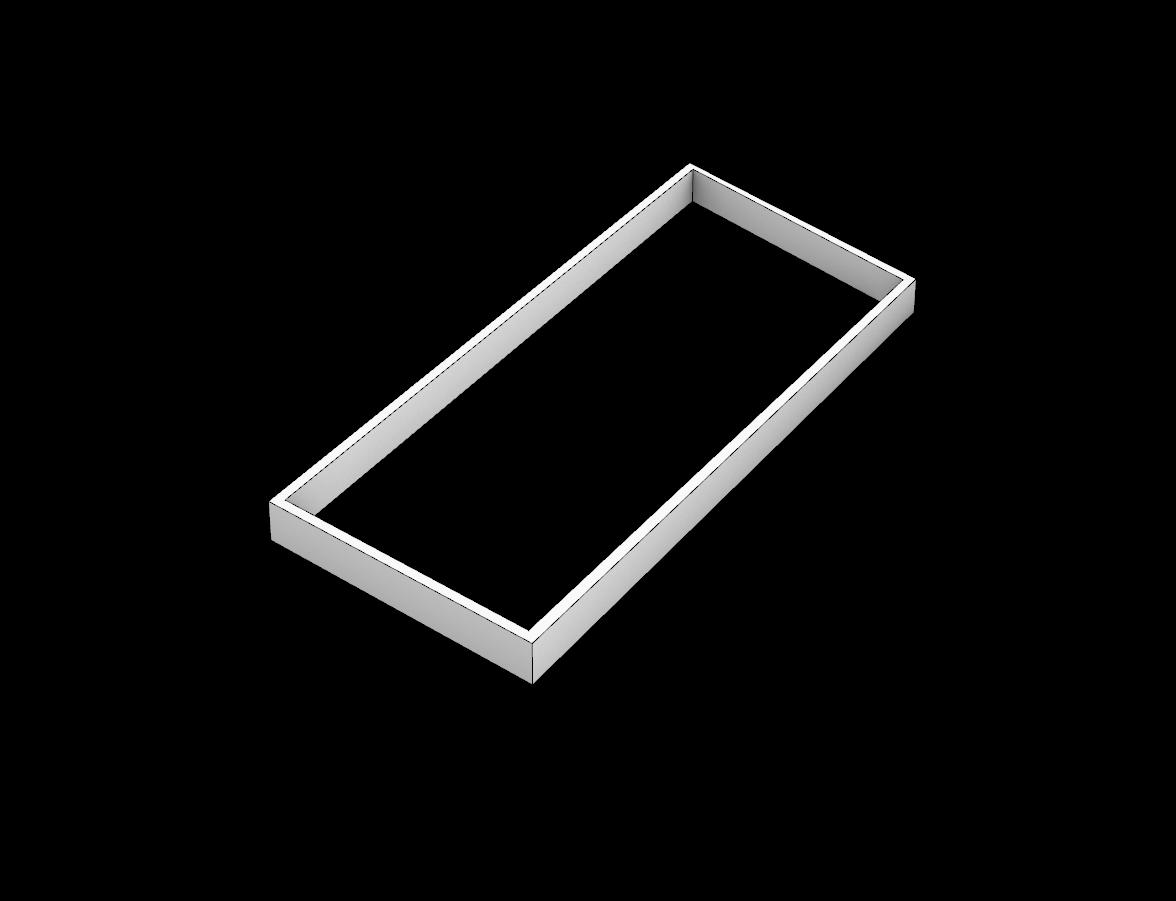
Because of symmetry at each floorplate, analyzing a single quadrant will provide U-value performance for the entire floor. Final analysis will be developed as a building-wide study using the project wireframe to absorb slight variabilities in area take-off frame lengths, and glass angle.
Preliminary Assembly Performance: 0.49 W/m2K
Target Assembly Performance: 0.44 W/m2K 11.3% over target Where balcony to be removed, placeholder values have been inserted into the thermal model; however, impact to assembly will be contingent on design intent and system required to meet performance criteria


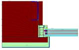


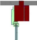


As the system design progressed, individual studies at each condition was done to determine the most optimal approach. Considerations for this included performance, architectural intent, cost, and any additional overhead associated with added trades and replacement strategies. The example to the right shows a study done evaluating different glass build-ups and impacts due to fabrication limitations.


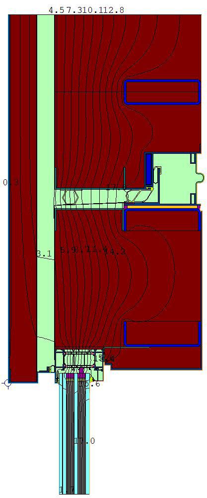
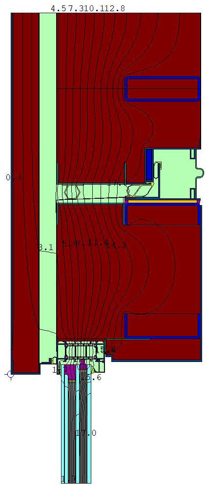


Herein is a snapshot of drawings produced for the first Design Assist submission to the design team for comment and review.

Location: Dubai, UAE
Architect: ACPV Architects
Role: Associate + Senior Associate
Scope: Concept Design - Schematic Design
Responsibilities included:
- Project management (internal and external)
- Coordination with Architects, Client, Executive Architects and related consultants
- System detailing and development in 2D (AutoCAD) and 3D (Rhino3D)
- Preliminary thermal analysis to NFRC standards
- Preliminary acoustic performance analysis
- Building access and maintenance strategy
- Material and system research
- Outline facade specification
- Preliminary pricing feedback from cost consultant


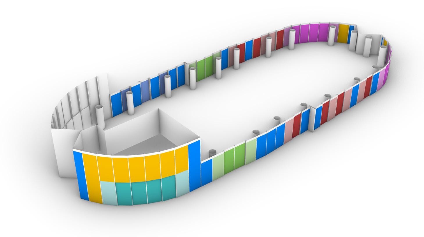
To ensure every facade system was captured, individual designations were established early in the project. This guided the coordination to ensure design intent was developed to the design team›s preferences. It also aided in early costing and area take-offs and allowed for quick updates as the design progressed.

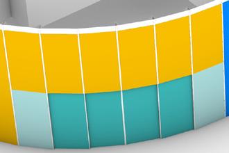
Architecturally, the facade system was intended to read as uniform. This required a thoughtful design that accommodated double-height spaces and operable sliding doors. Conversations with suppliers were key to unlocking a solution that met the design intent along with the budget. To the right is a comparison of the design intent at the single and double-height conditions which incorporate large sliding door units.



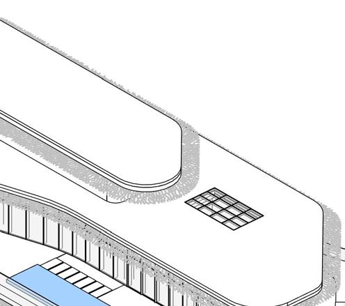

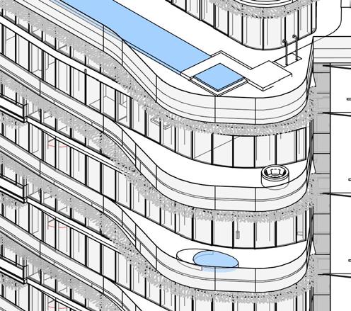
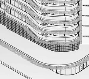
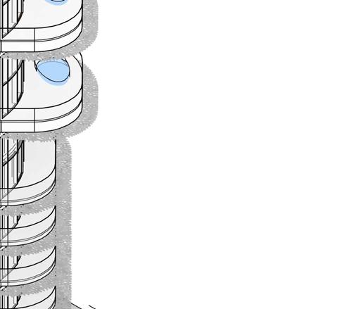
Because the program was high-end residential with limited interior access, glass cleaning and replacement strategies required exterior access with minimal architectural imposition. The vertical ‹V› facade at either short end of the building provided a clear, continuous path up the building to service the facade. This with the use of a bespoke gondola became the baseline strategy going into later design stages as illustrated in











Role: Associate
Scope: Schematic Design - Construction Administration
Responsibilities included:
- System detailing and development in 2D (AutoCAD) and 3D (Rhino3D)
- Material and system research
- Bidding and negotiation reviews
- Shop drawing review
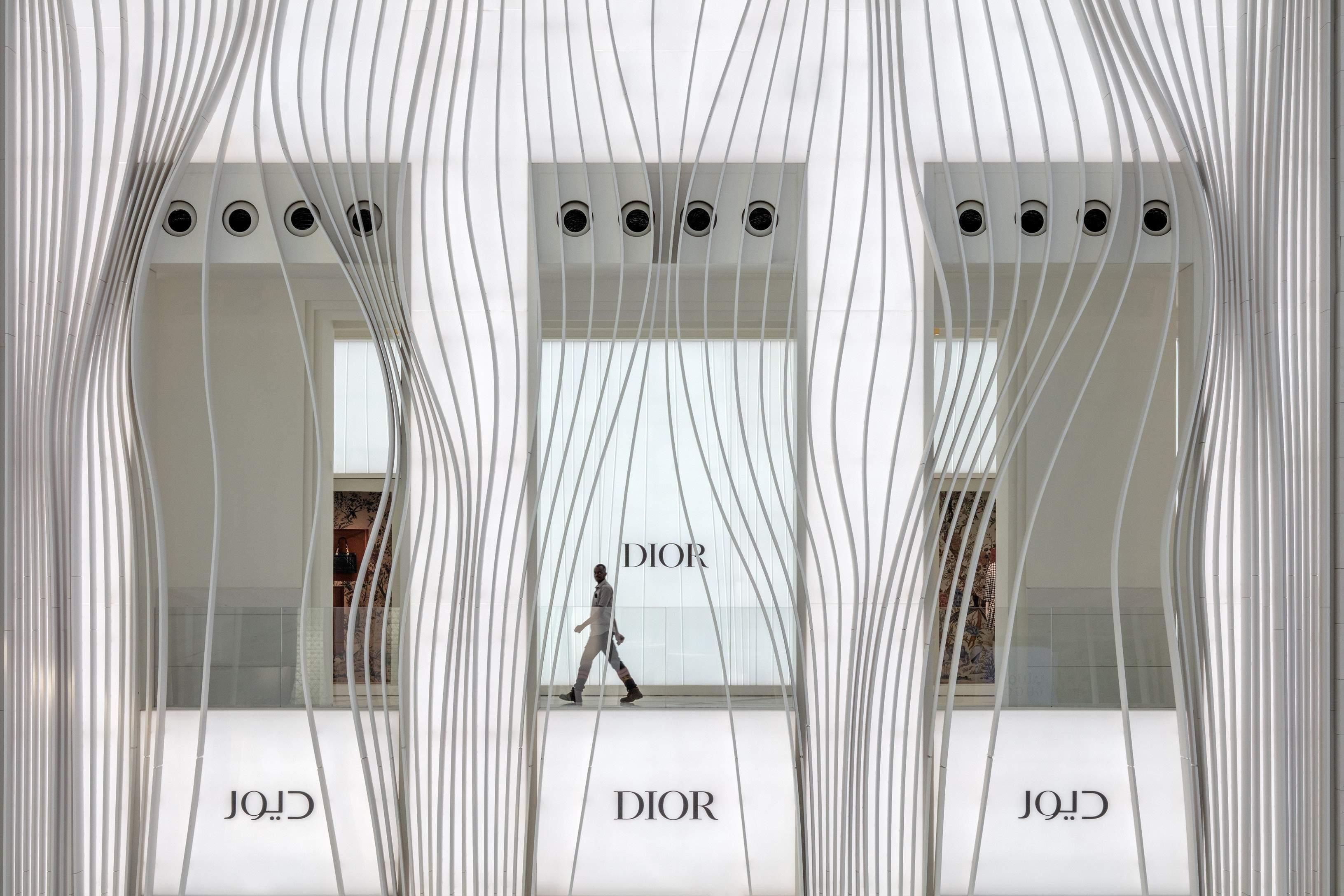


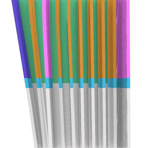
The 3-dimensional nature of the design intent required extensive study in modeling software to communicate joint strategy, how reinforcement was incorporated, and the bracketing approach for each prefabricated unit. Due to the back-lighting of the facade, it was a priority to have these connections well-documented for coordination.
AL-1 FIXTURE INTEGRATED INTO 500MM FINS
TYPICAL FIN PRE-INSTALLED TO KRION PANEL
BRACKET-INTEGRATED FIN [FIN SIZE AND TYPE VARIES]
AL-1 FIXTURE INTEGRATED INTO 500MM FINS
TYPICAL FIN PRE-INSTALLED TO KRION PANEL
BRACKET-INTEGRATED FIN [FIN SIZE AND TYPE VARIES]
FINS ARE 50MM SHORT OF THE FULL PREFABRICATED PANEL HEIGHT TO PROVIDE ACCESS TO HORIZONTAL JOINT AFTER PANELS ARE INSTALLED; JOINTS TO BE WELDED AND POLISHED TO A HAIRLINE APPEARANCE
FINS ARE 50MM SHORT OF THE FULL PREFABRICATED PANEL HEIGHT TO PROVIDE ACCESS TO HORIZONTAL JOINT AFTER PANELS ARE INSTALLED; JOINTS TO BE WELDED AND POLISHED TO A HAIRLINE APPEARANCE

GAPS BETWEEN FINS TO BE CLOSED ON-SITE WITH INFILL PANELS TO CREATE CONTINUOUS APPEARANCE
GAPS BETWEEN FINS TO BE CLOSED ON-SITE WITH INFILL PANELS TO CREATE CONTINUOUS APPEARANCE

FIN AT VERTICAL JOINT WELDED INTO PLACE [SEE MU2-D-02]
CONTINUOUS ALUMINUM PLATE BEHIND FIN
KRION PANEL FASTENER
HORIZONTAL JOINT
SITE-WELDED AFTER PANELS ARE INSTALLED
INSTALLED PANEL BELOW
CONTINUOUS ALUMINUM PLATE BEHIND FIN
KRION PANEL FASTENER
HORIZONTAL JOINT
SITE-WELDED AFTER PANELS ARE INSTALLED
INSTALLED PANEL BELOW
Herein is a snapshot of drawings produced for the design intent of the first visual mockup used to tender the project.
Drawing Set



Lusail Plaza Towers
Location: Lusail, Qatar
Architect: Foster + Partners
Role: Facade Consultant + Associate
Scope: Concept Design - Construction Administration
Responsibilities included:
- Project management (internal and external) during Construction Administration
- Coordination with Architects, Client, Executive Architects and related consultants
- System detailing and development in 2D (AutoCAD) and 3D (Rhino3D)
- Thermal analysis to EN standards
- Material and system research
- Design reports
- Shop drawing review
- Factory and site visits


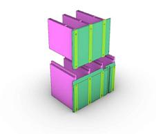
During the pre-tender design stage, materiality, constructability, and cost were driving factors that led a series of studies. Included was the system design which would have a direct impact on the facade articulation. In all cases, system performance, architectural intent, and material use was considered. To the right is a snapshot of studies condensed into final summaries used to communicate with the design team.

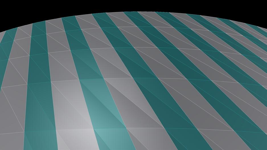


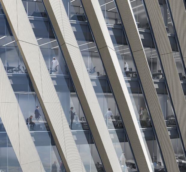


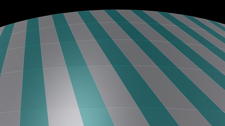


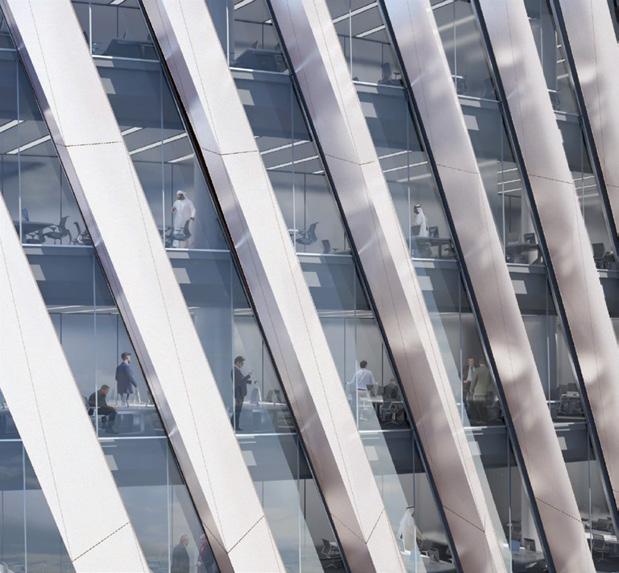


To achieve the design intent, programme, and budget, cold-bending at scale was a challenge that needed to be overcome in coordination with the design team and facade contractor. To do this, studies like the one illustrated to the right were developed, mocked-up, and used as the basis for vetting the system design during the Design Build stage of the project.
Tower | System Design


Tower | System Design


Access to the Building Maintenance Unit
The BMU sits in a dedicated room within the overall envelope of the building at the topmost floors. Access is provided through the common Vertical Transport core in the centre of each tower, from which operators can access the BMU room and machine directly.
BMU Door Concept
BMU in closed position Non insulated roof panels adjacent to BMU
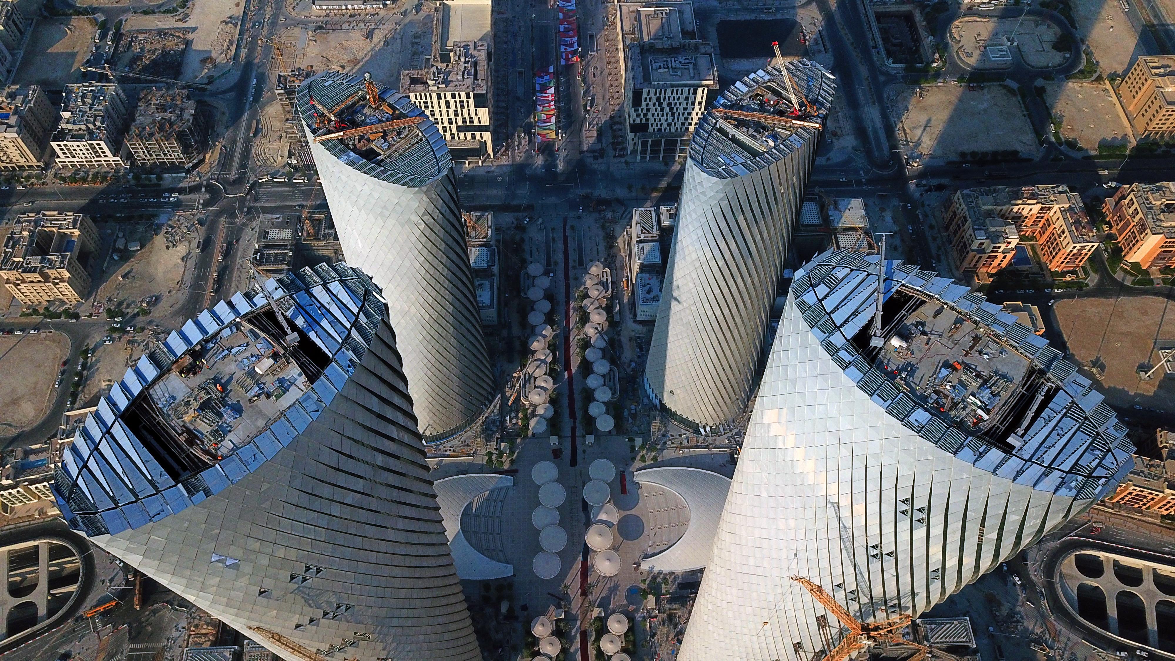
Because of the geometric constraints of the building mass along with the added complexity of the three-dimensional protrusions, a bespoke access and maintenance strategy was required. During Schematic Design, this was developed loosely and further invetigated post-tender during the Design Build period in coordination with the Architects of Record and related trades. The final built solution incorporates two hidden BMU units on the roof concealed by aluminum caps which mimic the roof facade.
The dedicated BMU room is enclosed with a horizontal screen that is designed to match the adjacent skylight system. The screen is not weather tight but does avert some rain and shade the unit; it is permanently mounted to the top of the jib, such that it does not have to retract or otherwise integrate into the skylight system adjacent. In this way, when the unit is parked, it will simultaneously enclose itself.
BMU Stability and Reactions
The weight-balance and the reactions to primary structure are provided on the following pages.
BMU Capacity
The BMU must carry the weight of the cradle as well as the weight of the material hoist. In the case of Lusail Towers, the material hoist must be able to carry a replacement glass unit as well as the suction cup rig to which it is attached. This total mass is estimated at 1000 kg.
Facade Panel Replacement Strategy
In the case that a glass unit needs to be replaced, this will occur from outside the building using the Glass Replacement Unit suspended from the BMU. The characteristics of the façade panels do not allow access for interior mounting. Because the IGUs are held in place with structural silicone, the initial access trip will release the existing panel by detaching the mechanical closure piece, and cutting the silicone bite free. The panel is released, the glazing surfaces cleaned, and a new panel brought in, which is then glazed in place and held there using temporary clips. After the required curing duration (weeks), another access trip is performed in order to remove the temporary clips and reinstall the exterior mechanical closure component. This process is illustrated below, following the BMU Stability and Reaction calculations. Protrusion replacement follows a similar procedure without the requirement for re-glazing.
Facade Panel Replacement Strategy
The roof door is attached to the BMU. When the BMU raises in to position, the door lifts with it

In the case that a glass unit needs to be replaced, this will occur from outside the building using the Glass Replacement Unit suspended from the BMU. The characteristics of the façade panels do not allow ac cess for interior mounting. Because the IGUs are held in place with structural silicone, the initial access trip will release the existing panel by detaching the mechanical closure piece, and cutting the silicone bite free. The panel is released, the glazing surfaces cleaned, and a new panel brought in, which is then glazed in place and held there us ing temporary clips. After the required curing duration (weeks), another access trip is performed in order to remove the temporary clips and reinstall the exterior mechanical closure component. This process is illus trated below, following the BMU Stability and Reaction calculations. Protrusion replacement follows a similar procedure without the requirement for re-glazing.


Location: Pennsylvania, USA
Architect: Weiss/Manfredi
Role: Facade Consultant, Associate + Senior Associate
Scope: Schematic Design - Construction Administration
Responsibilities included:
- Project management (internal and external)
- Coordination with Architects, Client, Executive Architects and related consultants
- System detailing and development in 2D (AutoCAD) and 3D (Rhino3D)
- Material and system research
- Bidding and negotiation reviews
- Shop drawing review
- Factory visits and visual mock-up reviews

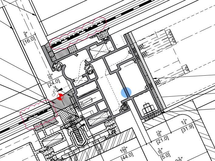
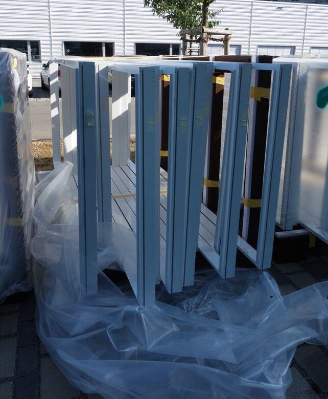
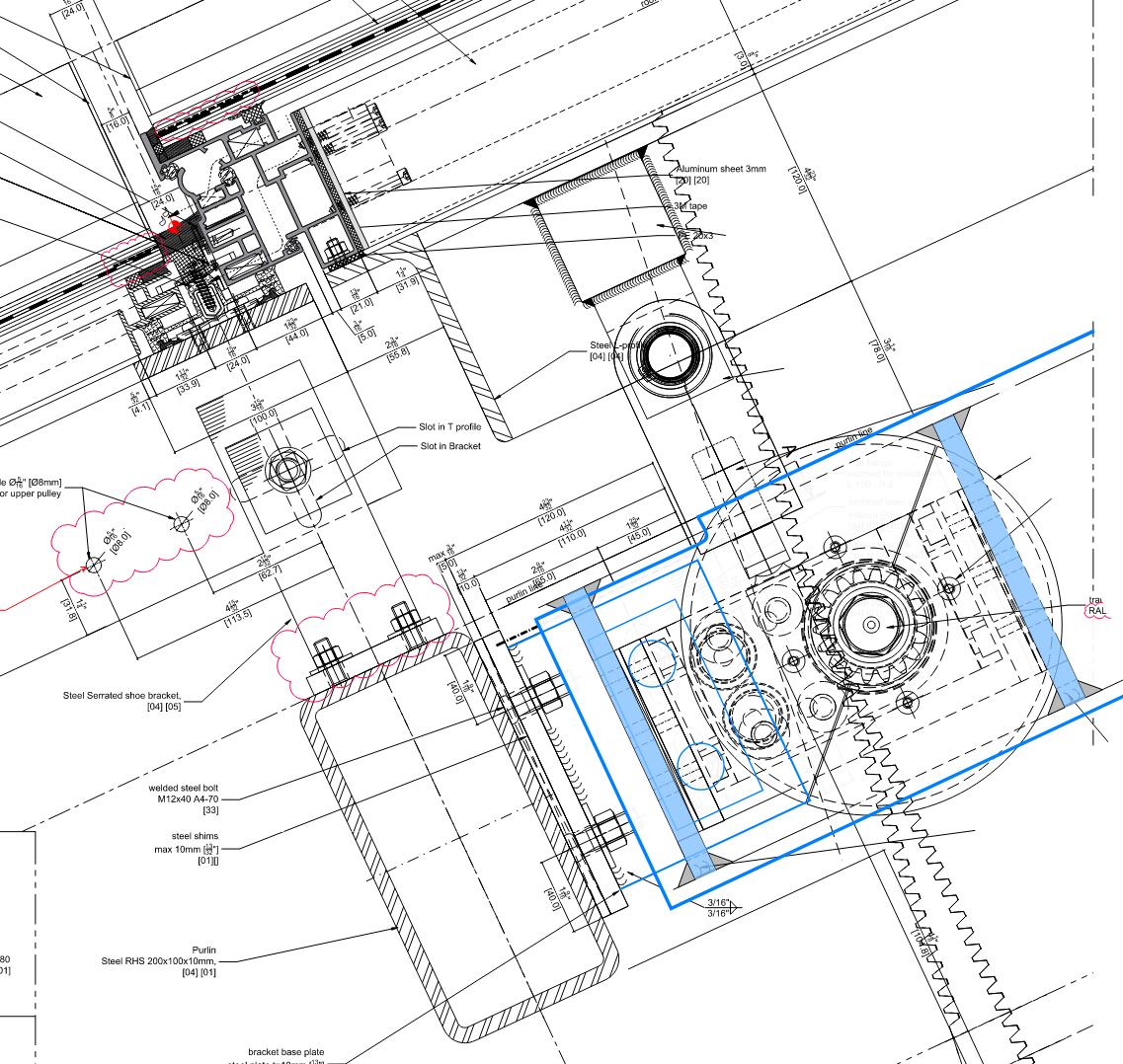
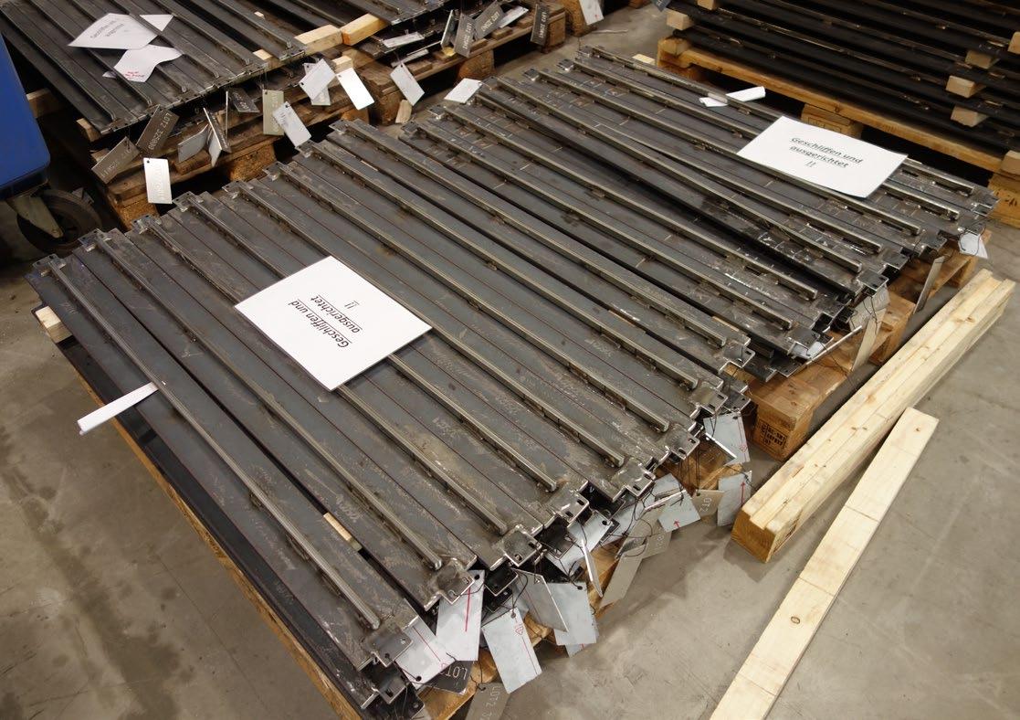
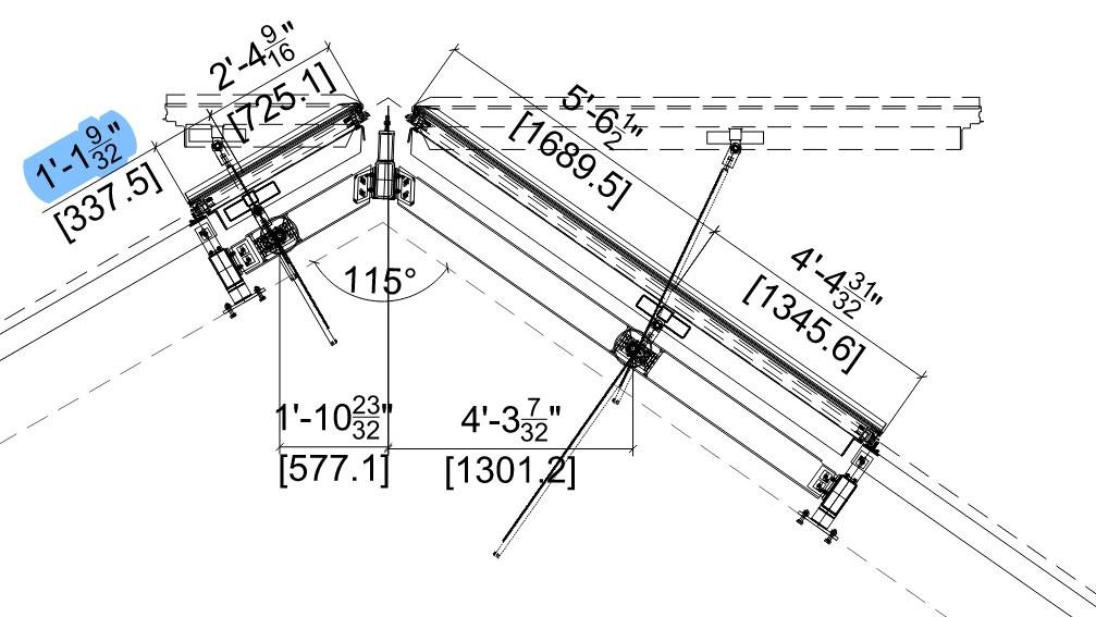
Regular factory visits were made to the facade contractor›s facilities based out of Germany. During these visits, glass, steel, and aluminum systems were evaluated for compliance with the design intent, quality of work, and coordination of any outstanding design solutions. To the right are extracts of factory reports completed for record and circulation to the design team and facade constractors for comment.
Additional holes not indicated in shop drawings were observed.


LONGWOOD GARDENS
Kennett Square, PA
Observation Report #2 Roschmann Factory Visit
Dates of Observation: June 7 2022
Date of Issue: June 10 2022

Kennett Square, PA
Observation Report #2 Roschmann Factory Visit
Dates of Observation: June 7 2022
Date of Issue: June 10 2022


Kennett Square, PA
Roschmann Factory Visit June 7 2022 10 2022


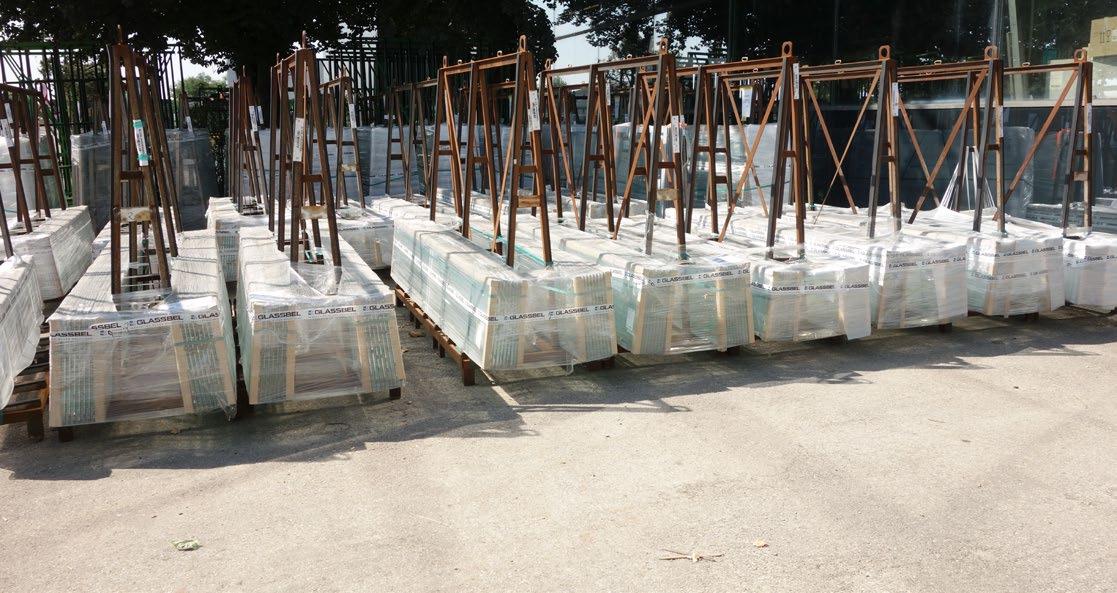

Herein is a snapshot of drawings produced for the tender package. Included in the project are two types of operables: bespoke over-sized roof operables and vertical bifolding doors. Included were bespoke system extrusions paired with standard systems to manage costs while maintaining the desired design intent.


Pendry Hotel
Location: New York, USA
Architect: SOM
Role: Facade Consultant + Associate
Scope: Design Development - Construction Administration
Responsibilities included:
- System detailing and development in 2D (AutoCAD) and 3D (Rhino3D)
- Material and system research
- Bidding and negotiation reviews
- Shop drawing review
- Performance mock-up review

Working initially from a rendering as the design intent, studies and research was done to determine the best option for the horizontal banding at each floor. Because the design intent was to have a dark spandrel panel that had a natural appearance, metal panel was not considered. Instead, precast and natural stone was reviewed for longevity, aesthetic viability, weight, and cost.

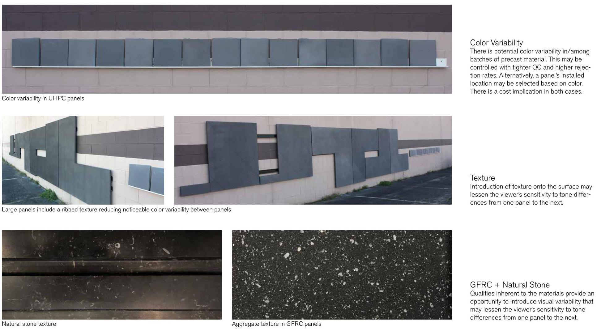
Similar to the spandrel panel, the glass used on the project needed to meet the design intent while responding to programmed interior spaces and the undulating/curved glass that introduced both concave and convex units to the project. Back-paininting, alternating low-e coatings, and bodytinted glass were all studied during the selection process.


Reference images showing how the final system design and built work closely resemblers the original design intent. Through mock-ups using samples and full-scale studies, the options were narrowed to best represent the design intent.


AINSLEY MCMASTER | Selected Works end of document