WORK EXPERIENCE
JOE MILES ARCHITECT, LONDON - REMOTELY (2021-2023 )
ROLE:
PROJECTS:
BIM COORDINATOR & PROJECT ASSISTANT ARCHITECT
-58 SCRUTON STREET (453 sqm)
-20 DONOVAN AVUENUE (200 sqm)
-AVUENUE HEIGHTS (87 sqm)
-44 BALLARDS LANE (519 sqm)
-MILDMARY COURT (798 sqm)
-COMMERCIAL
-RESIDENTIAL
-MIXED USE
-COMMERCIAL
-MIXED USE
• BIM Implementation: Successfully implemented BIM methodologies and workflows, establishing project-specific BIM requirements and standards.
• BIM Modeling: Created and managed a significant number of BIM models, focusing on accuracy, detail, and associated data attributes, while also producing high-quality architectural drawings.
• Documentation Management: Skillfully managed project documentation, including tender and construction documents, producing over 400 sheets with precision and adherence to standards.
• Design Support: Provided valuable design support to the architectural team, contributing to concept development, design iterations, and the production of high-quality drawings, sketches, and models.
• Involvement in All Building Process Stages: Played a pivotal role from concept development to construction, ensuring design integrity and successful project delivery.
• Problem Solving: Exhibited exceptional problem-solving abilities, addressing design challenges, resolving conflicts, and implementing innovative solutions to ensure successful project outcomes.
VersPro ltd, LONDON - REMOTELY (2022)
ROLE:
PROJECTS:
BIM SPECIALIST & INTERIOR DESIGNER
Concept design: 12 Projects
-Ringo Housing Cooperative , 226-Meena S , 248-Nick and Simone W , 255-Donna W , 257-Vic and Emma G , 26-Mandy.
Planning and Working drawings: 6 Projects
-267-Anita , 249-Sergi TF , UK011-Karen.
• Existing Case Modeling: Utilized point cloud data and Matterport laser scans to accurately model the existing conditions of the project.Created detailed BIM models that captured the precise measurements and characteristics of the space.
• Interior Design: Developed multiple design options to meet the unique requirements and preferences of clients. Presented visually compelling and comprehensive design proposals for spatial layouts.
• Visualization and Rendering: Utilized advanced visualization tools to create realistic renderings and visualizations of interior spaces.
Ahmed M. Attia 4
BDA 2019 Bachelor at Architecture and Engineering Modern Academy (Egypt)
SCHOLARSHIP 2020 KAITCH- Architecture BIM scholarship ( 5 month ) (Egypt)
KAITECH, CAIRO - (2020 - 2023)
ROLE: BIM COORDINATOR


PROJECTS:
- OWEST THE NEW CITY- 6OCT , EGYPT -COMMERCIAL&RESIDENTIAL
-ART ISLAND ELGOUNA- ELGOUNA , EGYPT -RESIDENTIAL
-EIPICO FACTORY- 10TH OF RAMADAN , EGYPT -COMMERCIAL
-AL BARSHA SCHOOL- AL BARSHA , UIA -LANDSCAPE
• BIM Model Development: Led the development of BIM models for the first, second, fifth, and sixth districts of the Owest project. Created architecture BIM models for 20 different types, each with an area of 2000 m2/type.
• Clash Detection and Avoidance: Utilized Navisworks for clash detection, identifying clashes and conflicts between various building elements. Developed clash avoidance strategies and collaborated with multidisciplinary teams to resolve clashes effectively.
• Coordination Data Extraction: Extracted coordination data from the BIM models, facilitating effective collaboration and communication among project stakeholders. Generated accurate quantity takeoffs and reports to support cost estimation and procurement activities.
• Process Development and Automation: Leveraged Dynamo for Revit to develop and automate various BIM processes. Streamlined workflows, reducing manual efforts and enhancing productivity within the BIM environment.
• Shop Drawings: Produced detailed shop drawings based on the BIM models, providing clear and precise instructions for manufacturing and construction processes. Developed accurate drawings that showcased dimensions, materials, finishes, and assembly details to guide fabricators and contractors.
• Data Management: Developed strategies for efficient data management within BIM projects, ensuring accuracy, consistency, and informed decision-making. MY WORKFLOW AND COMPETENCE
Ahmed M. Attia 5 Revit Max API API 3D Modeling Tools Visual Programs 2D
clashes
Rendering / VR Tools
Design tools
tools
Rhinoceros
Dynamo Grasshopper
Ahmed M. Attia 6 @JMA
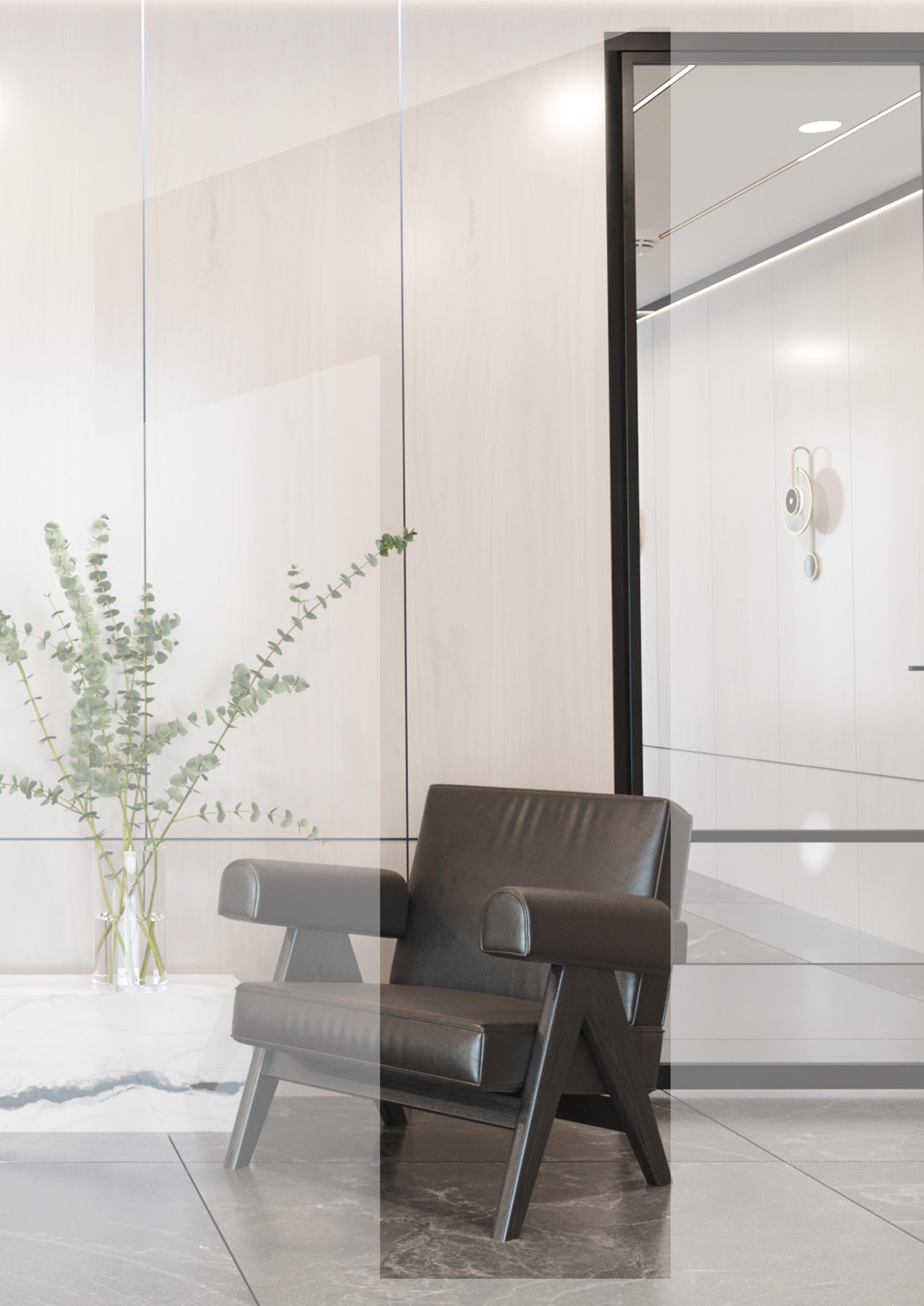
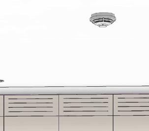
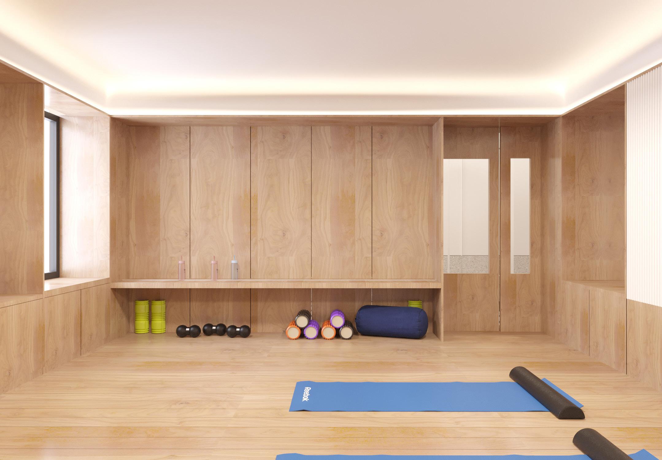
AVEUNE HEGHITS Lobby&Gym and Penthouse
YEAR : 2023
LOCATION : Avenue Rd, Highgate, N6 5DS
TOTAL AREA: 180 SQM
INTERIOR DESGINER: JMA

PROJECT DESCRIPTION:


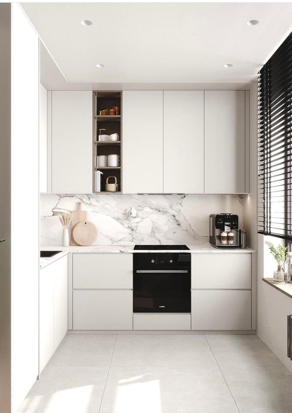
The proposed project consists of a building that includes a lobby, gym, and penthouse. The lobby and gym are located on the ground floor, while the penthouse is situated on the 4th floor. The design focuses on creating a charming aesthetic, utilizing elegant design elements, captivating color schemes, and high-quality materials. The goal is to achieve a sophisticated and visually pleasing environment, incorporating natural light and prioritizing user comfort.
MY SCOPE OF WORK:
• INTERIOR DESIGN : E ncompassed designing and modeling the lobby, gym, and penthouse areas.
• DETAILED 3D MODEL DEVELOPMENT : D eveloped a precise and comprehensive 3D model for the project.
• COMPREHENSIVE CONSTRUCTION DRAWINGS : P roduced over 50 construction drawings with precise instructions for the construction team.


• COLLABORATION WITH STAKEHOLDERS : C ollaborated with project stakeholders to address design challenges and provide innovative solutions.
• AESTHETIC AND FUNCTIONAL DESIGN INTEGRATION : C ombined aesthetic appeal with functional design principles in the project.
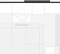
SELECTED WORK 7 44 m² RECEPTION G.01 39 m² GYM G.02
BIM & PROJECT ASSISTANT ARCHITECT
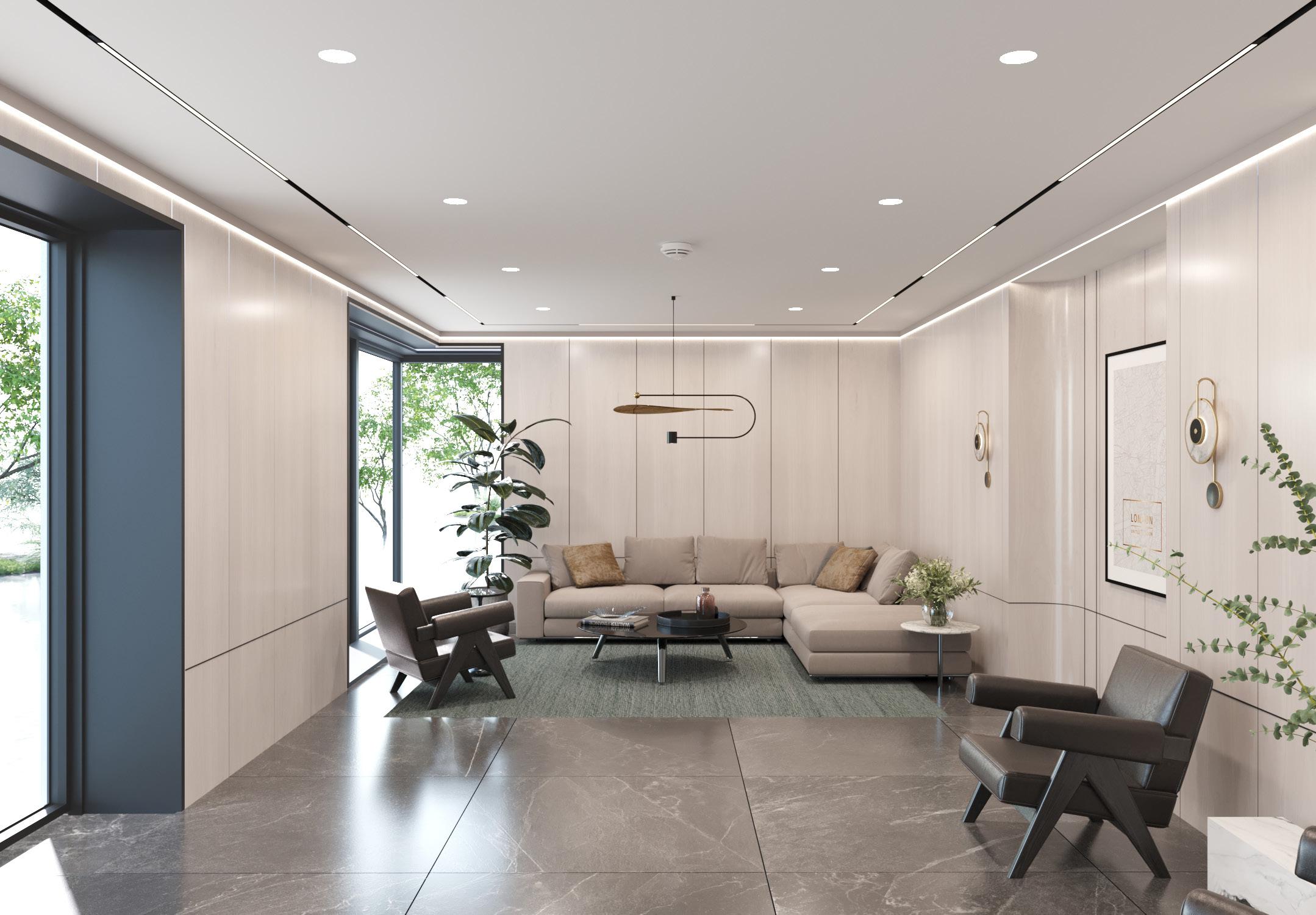


Ahmed M. Attia BIM MODEL MADE BY ME @JMA


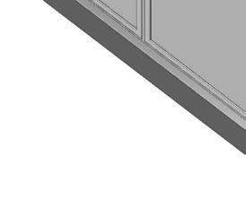

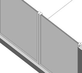
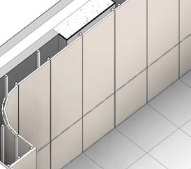
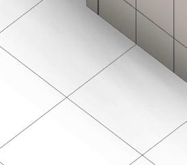

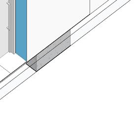

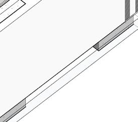


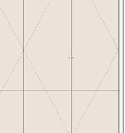
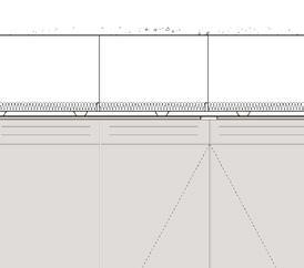
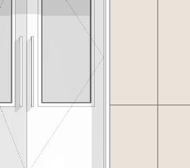


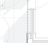
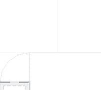
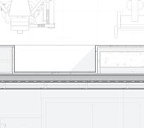
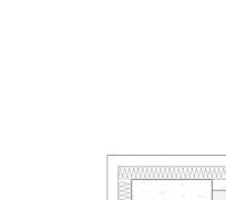
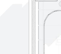
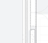
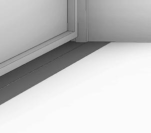
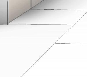
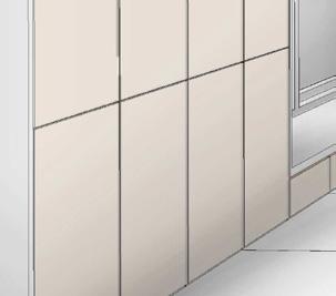
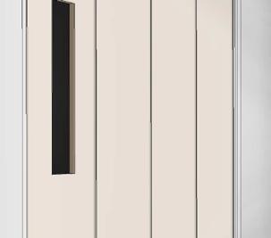
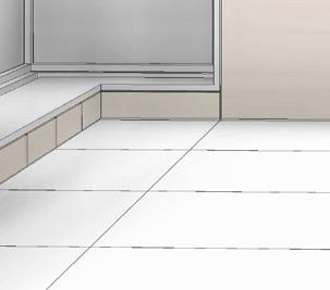
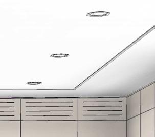
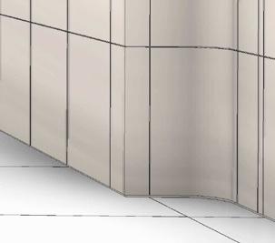
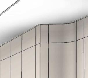
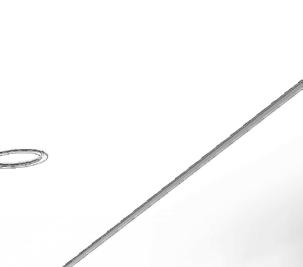
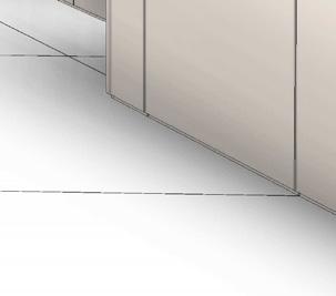
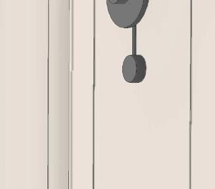
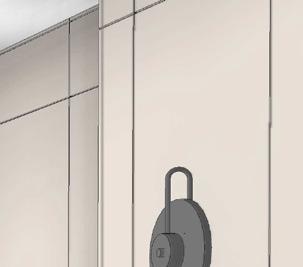
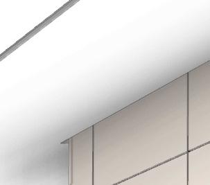
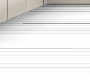
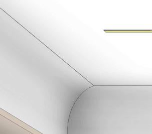
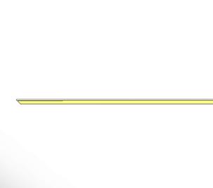
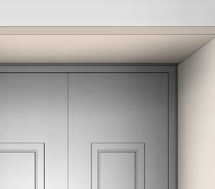
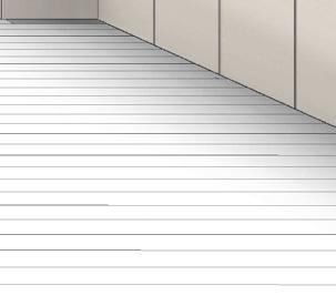
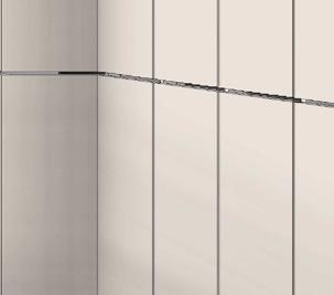
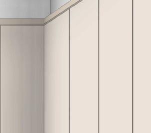
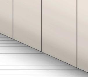
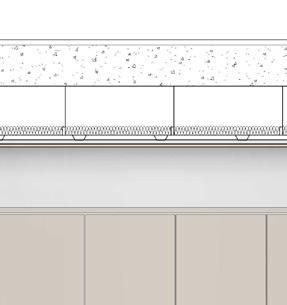
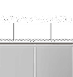
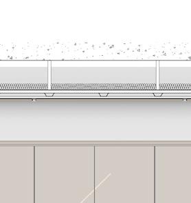
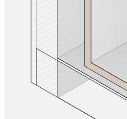
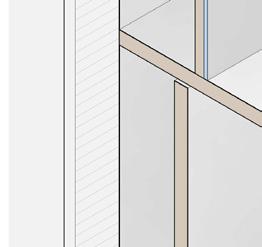
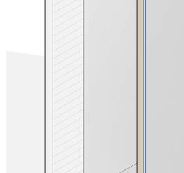
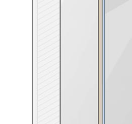
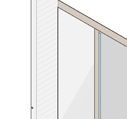
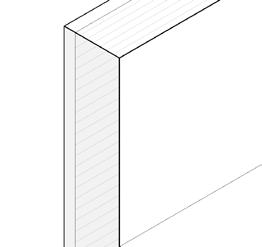
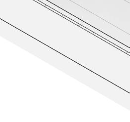
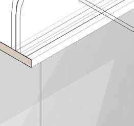
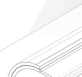
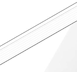
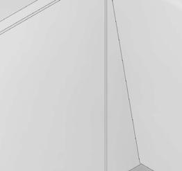
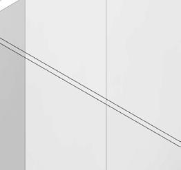
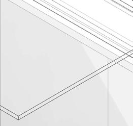
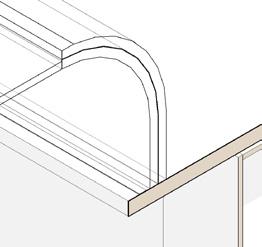
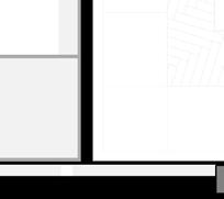
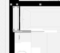
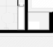
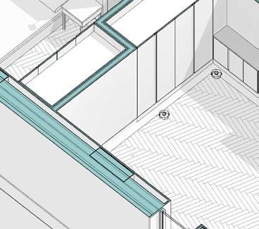
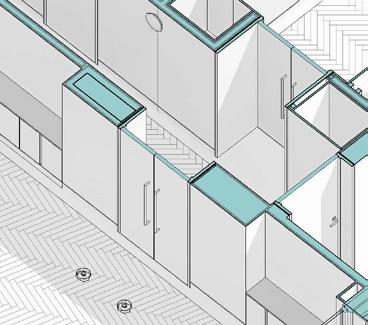
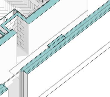
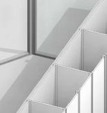
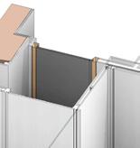
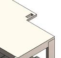
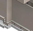
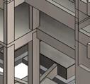
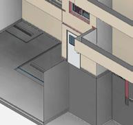
FFL: GROUND FLOOR-00 +65.600 m 1 2 3 FCL: U/S GROUND FLOOR CEILING +68.065 m USS: 01 +68.430 m K21.160 Veneered MDF panel Frato Kandy Wall Lamp as per M&E spec Cabling for light to be installed with plenty of slack to allow for opening K21.160 Access Veneered MDF door FFL: GROUND FLOOR-00 +65.600 m C D B Slope has been moved towards the lobby by 25mm to match with tile joints USS: 01 +68.430 m HIGH FLOOR +65.800 m K21.160 Veneered MDF panel G.02.D01 G.01.D03 K21.160 Access Veneered MDF door SELECTED WORK 9 LOBBY LOBBY&CORRIDOR ELEVATIONS 3D PLAN


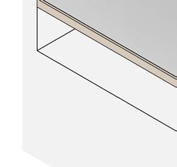


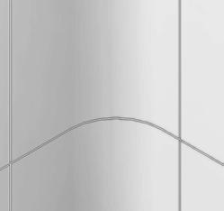


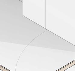


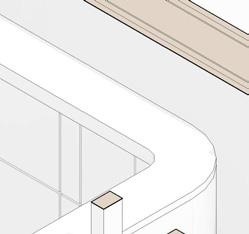
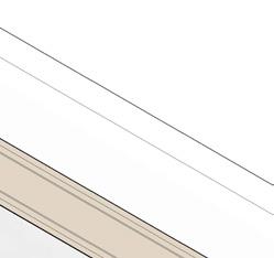

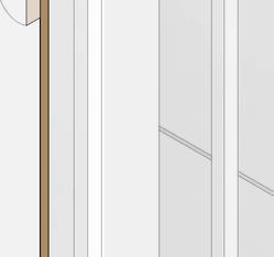
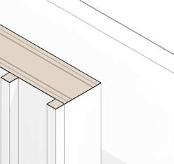

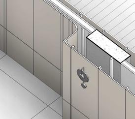
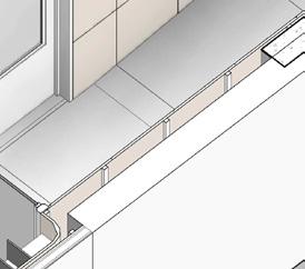
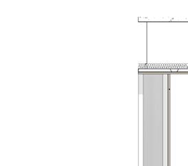
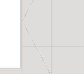
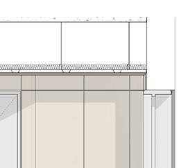
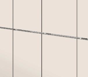
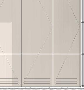
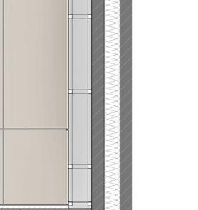
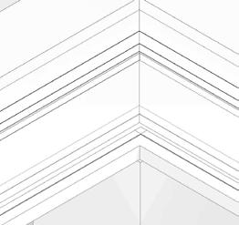
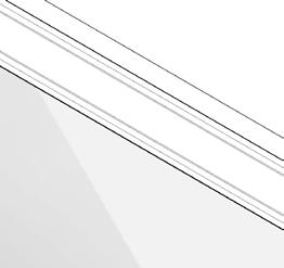
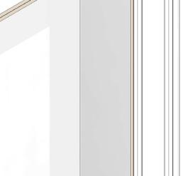
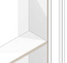
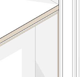
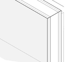
CL CL CL CL CL CL CL LC CL CL 30x30 Battens 80 125 330 60 20 45 210 R120 R 138 K10.127 Plasterboard Partition SVP K21.160 MDF Veneered Panel 30 18 301253030 20 30 128 30 335 EQ 2038 EQ 380 AD_(22)_111 2 AD_(22)_111 2 N10.153 Oak veneer panels 168 4 195 4 45 4 597 4 597 4 45 4 126 4 65 4 168 M40.120 Tile to lobby 5mm shadow gap to be centered on timber floor joint below 5mm shadow gap to be centered on timber floor joint below 4mm shadow gap to be centered on grout tile below 4mm shadow gap to be centered on grout tile below 5mm shadow gap to be centered on timber floor joint below 5mm shadow gap to be centered on timber floor joint below 5mm shadow gap to be centered on timber floor joint below 5mm shadow gap to be centered on timber floor joint below R120 R 138 Ahmed M. Attia 10 LOBBY RECESSED WALL ASSEMBLY
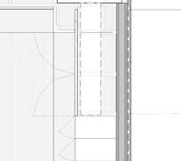
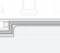
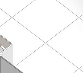
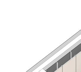
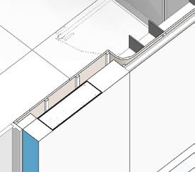
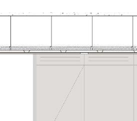
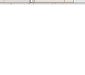
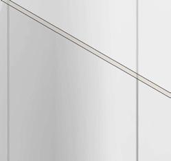
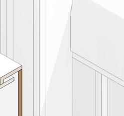
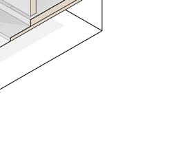
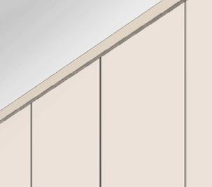
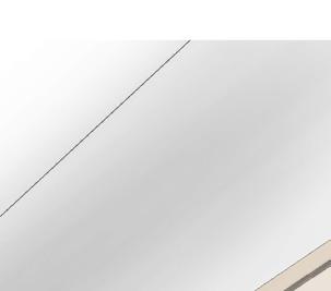
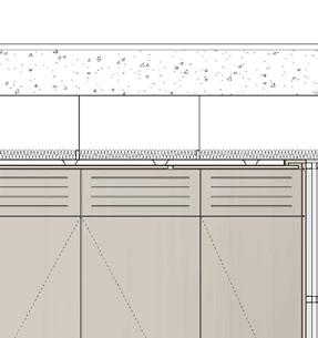
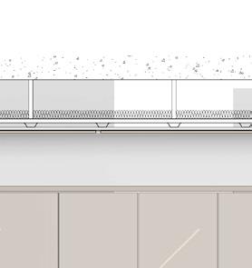
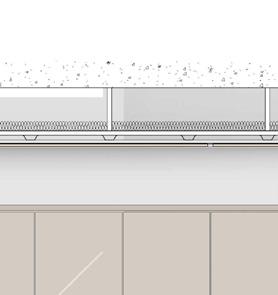
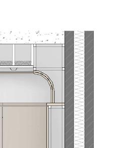
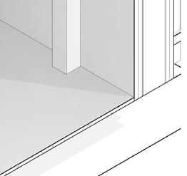
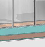
SELECTED WORK 11 FFL: GROUND FLOOR-00 +65.600 m FCL: U/S GROUND FLOOR CEILING +68.065 m USS: 01 +68.430 m 10 mm Shadow gap 4 mm Shadow gap 380 235 1616 610 4 mm Shadow gap 4 mm Shadow gap 4 mm Shadow gap K10.130 Ceiling R200 15 Recessed strip light to gym ceiling K10.127 Plasterboard Partition N10.153 Oak veneer panels K21.160 MDF Veneered Panel 8 mm Shadow gap 8 mm Shadow gap 10 mm Shadow gap 30 20 18 30 278 98 K21.100 Timber Floor to Gym M40.120 Tile to lobby floor


Ahmed M. Attia BIM MODEL MADE BY ME @JMA


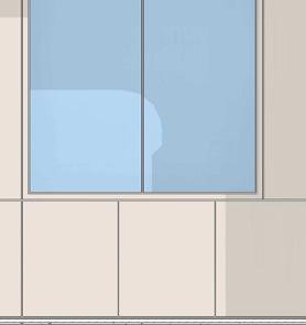

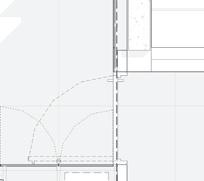
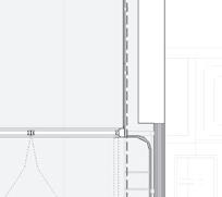
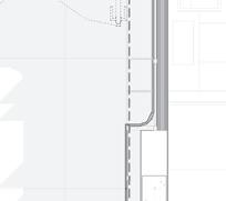
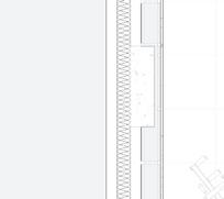
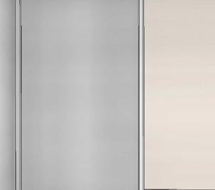
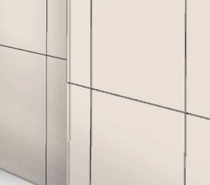
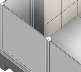
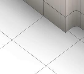
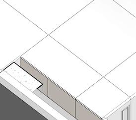
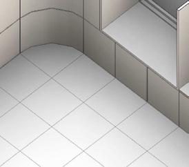
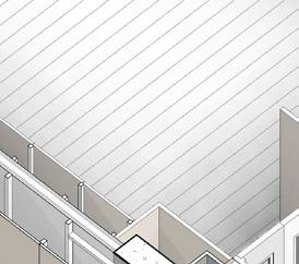
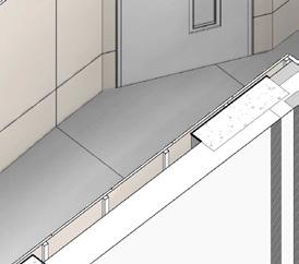
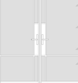
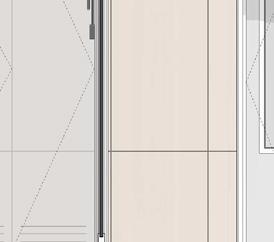
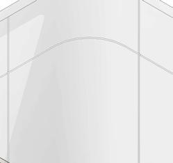
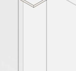
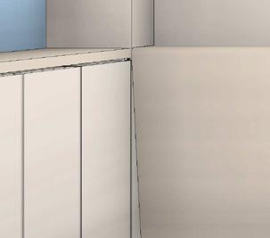
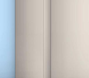
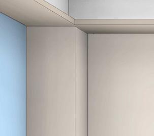
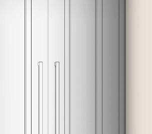
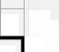
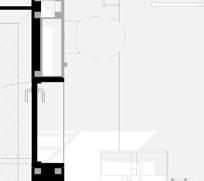
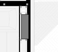
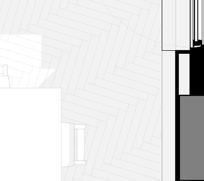
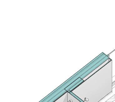
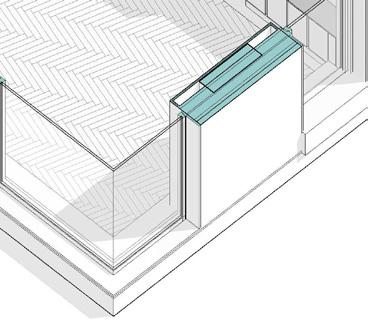
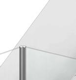
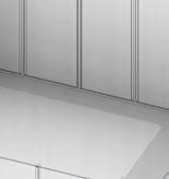
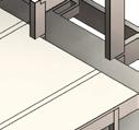
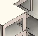
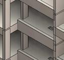
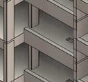
SELECTED WORK A C D B N10.153 Oak veneer panels N10.153 Oak veneer USS: 01 +68.430 m FFL: GROUND FLOOR-00 +65.600 m 1 2 3 N10.153 Oak veneer Panels K21.170 Mirrored Panels USS: 01 +68.430 m FCL: U/S CORRDIOR FCL +67.965 m GYM GYM&LOBBY ELEVATIONS 3D PLAN


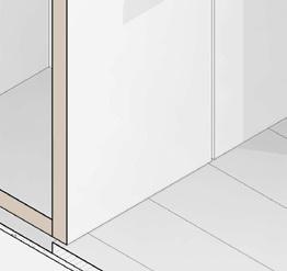
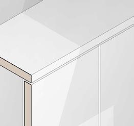


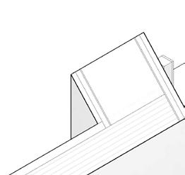
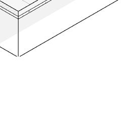


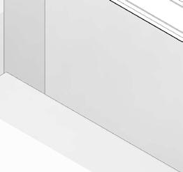


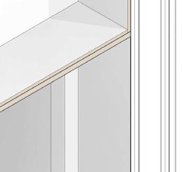
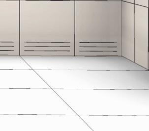
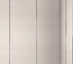
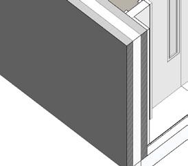
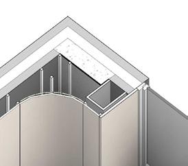
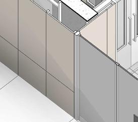
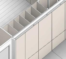
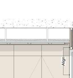
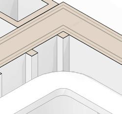
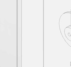
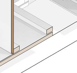
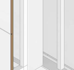
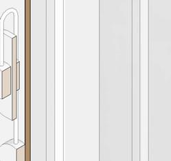
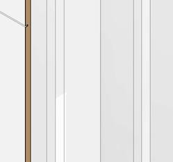
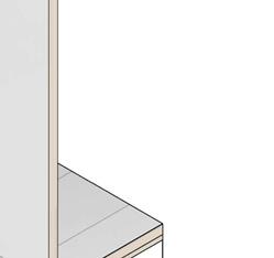
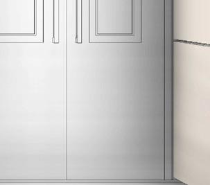
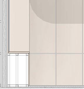
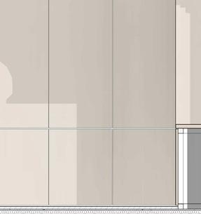
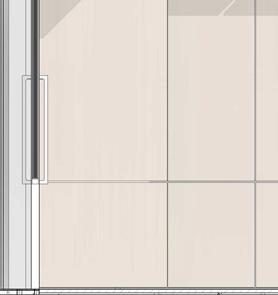
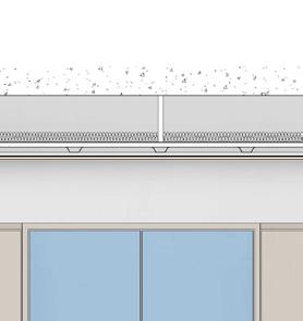
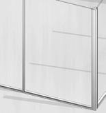
Align LC Align N10.153 Acess Oak veneer panels N10.151 Gym bench N10.153 Oak veneer panels K21.170 Mirrored Panels K21.100 Timber Floor to Gym 8 30 45 361 45 125 30 18 K21.160 MDF Veneered panels 270 250 5 K21.160 MDF Veneered panels K21.100 Timber Floor to Gym N10.150 Gym lockers N10.153 Oak veneer panels Ahmed M. Attia 14 GYM PANELING & BENCH ASSEMBLY
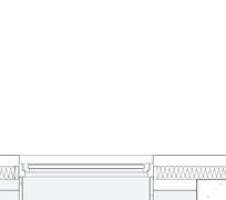
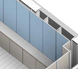
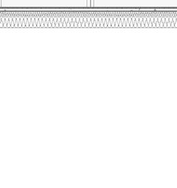
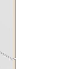
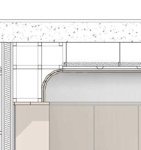
Align Align FFL: GROUND FLOOR-00 +65.600 m USS: 01 +68.430 m FCL: U/S CORRDIOR FCL +67.965 m 30 615 1478 30 335 335 15 N10.153 Oak veneer panels N10.151 Gym bench Timber frame N10.153 Oak veneer panels N10.153 Oak veneer panels K10.130 Ceiling K21.170 Mirrored Panels Recessed strip light K10.127 Plasterboard Partition K21.160 Veneered MDF panel 50 1484 50 5 8 R20 15 SELECTED WORK 15
@JMA


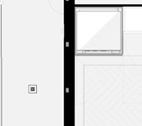


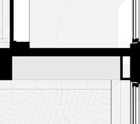
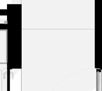


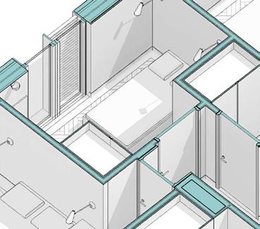
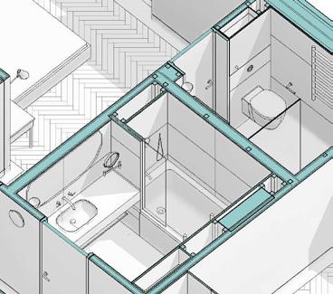
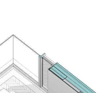
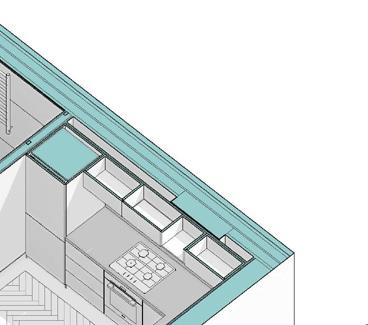

SELECTED WORK 24 m² LIVING ROOM DINING ROOM 4.02 3 m² SHOWER ROOM 4.06 5 m² BATHROOM 4.05 13 m² BEDROOM 2 4.04 7 m² BEDROOM 1 4.03 11 m² BEDROOM 3 4.08 KITCHEN 4.07 KITCHEN SHOWER ROOM MASTER BEDROOM BEDROOM BEDROOM LIVING ROOM BATHROOM BIM & PROJECT ASSISTANT ARCHITECT Proposed Penthouse Plan Proposed Penthouse 3D Plan
Ahmed M. Attia 18 @JMA
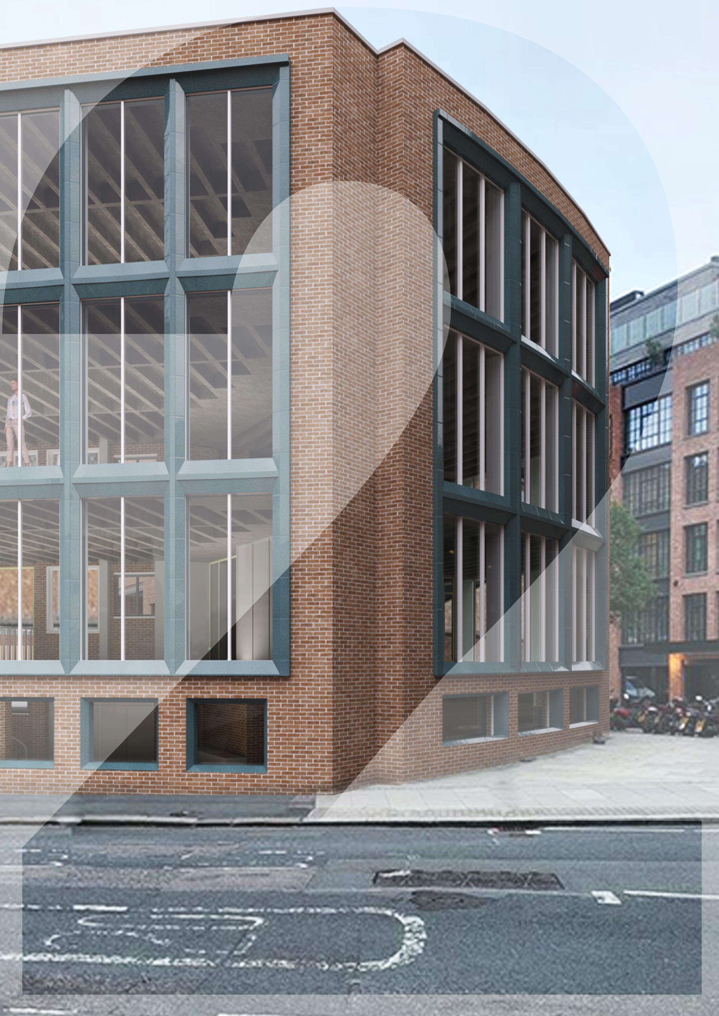
INK YARD
COMMERTIAL BUILDING
YEAR : 2023
LOCATION : 58-62 SCRUTTON STREET, LONDON
TOTAL GROSS EXTERNAL AREA: 1944 SQM
ARCHITECT: JMA
PROJECT DESCRIPTION:
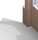
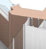
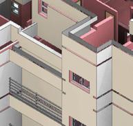
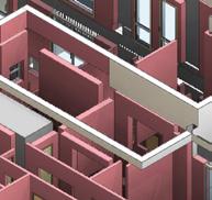
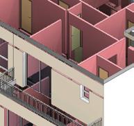
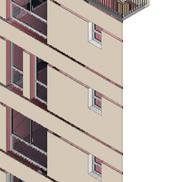
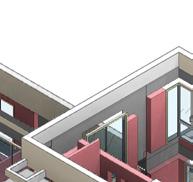
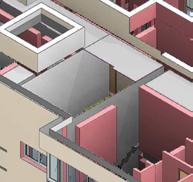
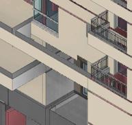
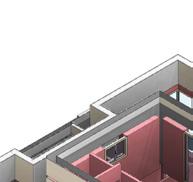
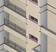
The project involves converting an existing building into an office with a ground floor cafe. The design includes multiple floors, from basement to rooftop, with a focus on creating functional and visually appealing spaces. The proposed design features new elevations with handcrafted terracotta elements, adding elegance to the building’s facade. The ground floor will house a stylish cafe, while the office areas on the ground and second floors will offer open workspace and meeting rooms for collaboration. The design emphasizes comfort, flexibility, and natural light, promoting productivity. Sustainability and energy-efficient solutions are incorporated throughout the project.
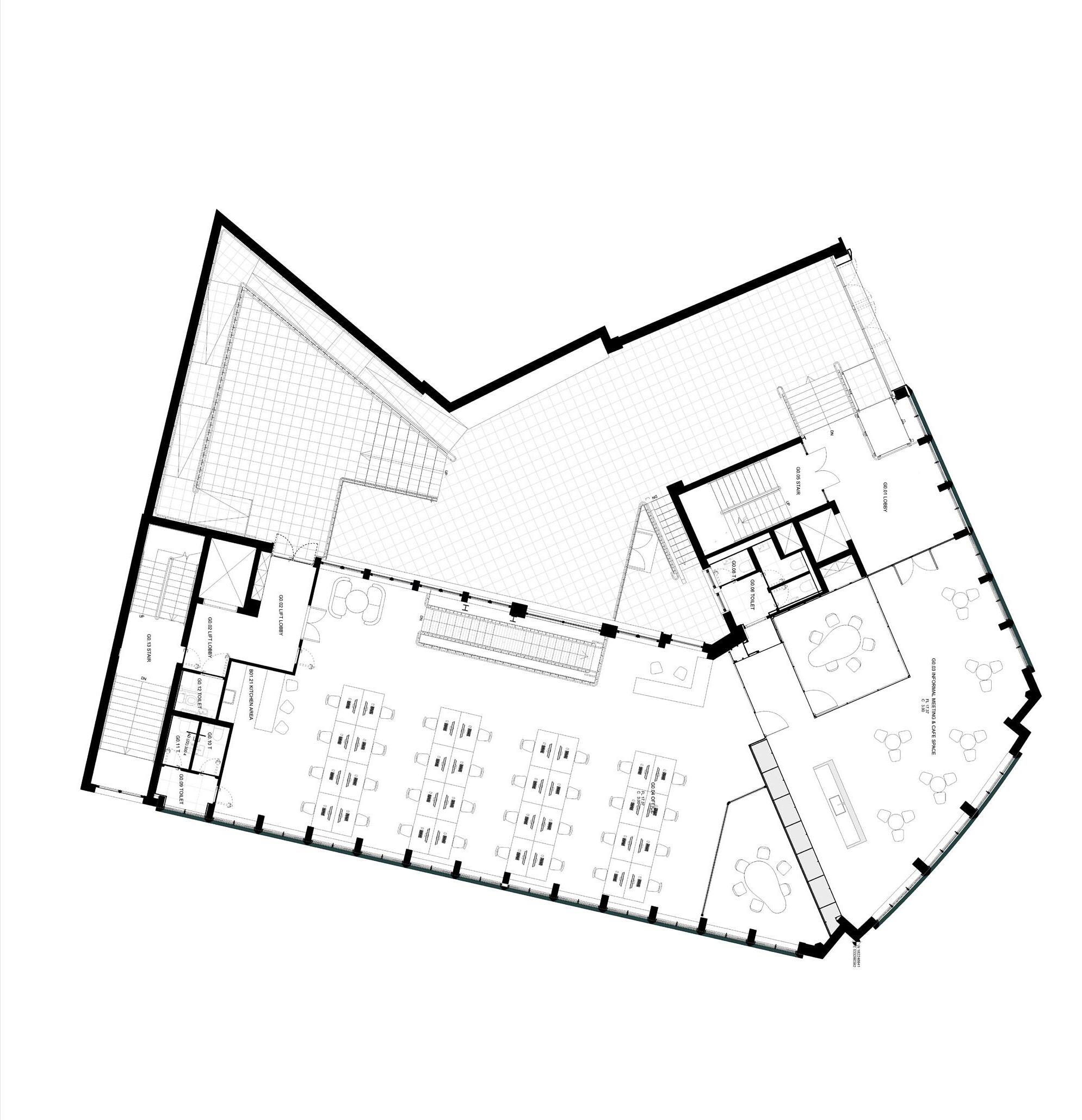
MY SCOPE OF WORK:
• Detailed 3D BIM Model Creation: Developed a comprehensive BIM model with architectural, structural, and MEP elements.
• Design Improvement: Enhanced design of GA main plans, cafe, lobby, bathrooms, and facade development.
• End-to-End Project Involvement: Produced 300+ sheets, including GA main plans, 3D details, and construction drawings for cafe, lobby, bathrooms, and facade.
• Clash Detection and Coordination: Identified and resolved clashes, coordinating with stakeholders such as engineers and consultants.ment activities, obtaining quotes, and reviewing specifications.
SELECTED WORK 19
BIM & PROJECT ASSISTANT ARCHITECT
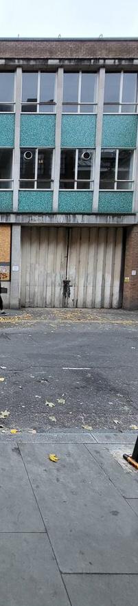

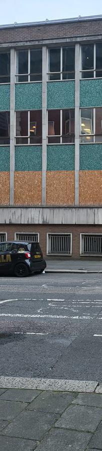
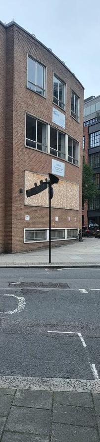
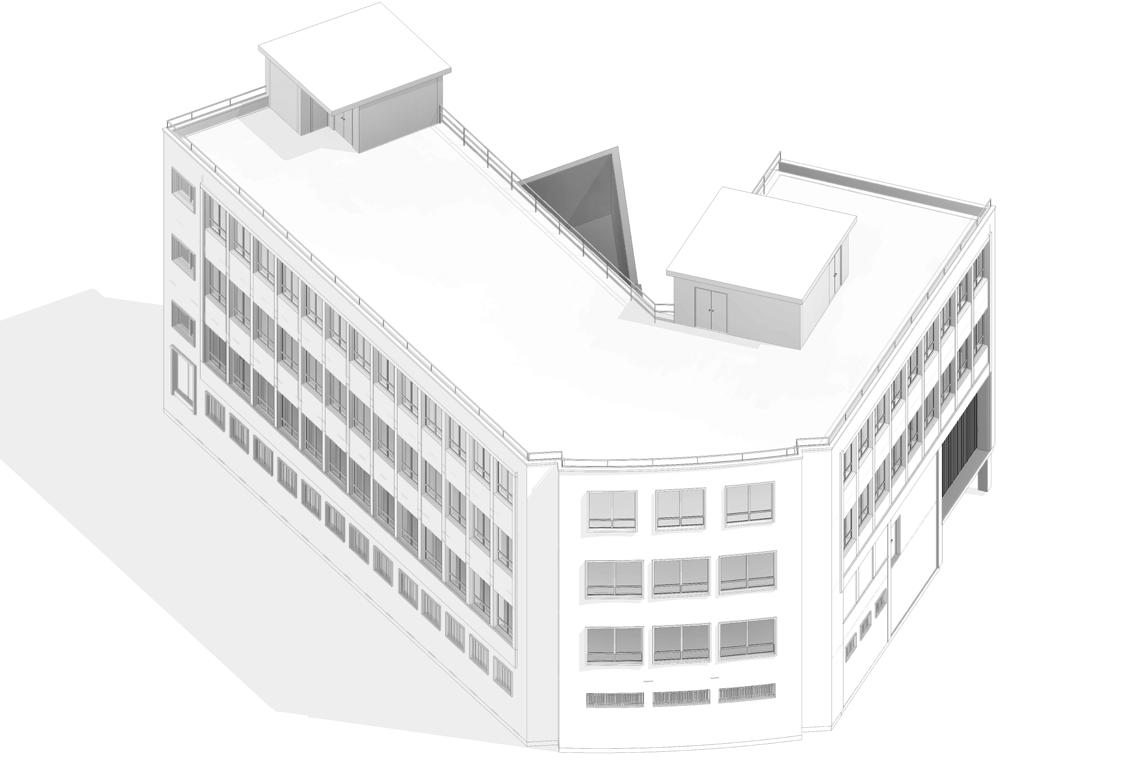
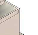
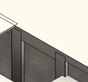
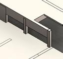
Ahmed M. Attia 20 EXISTING BUILDING
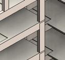
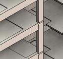
DEMOLITION BIM MODEL CREATED BY ME
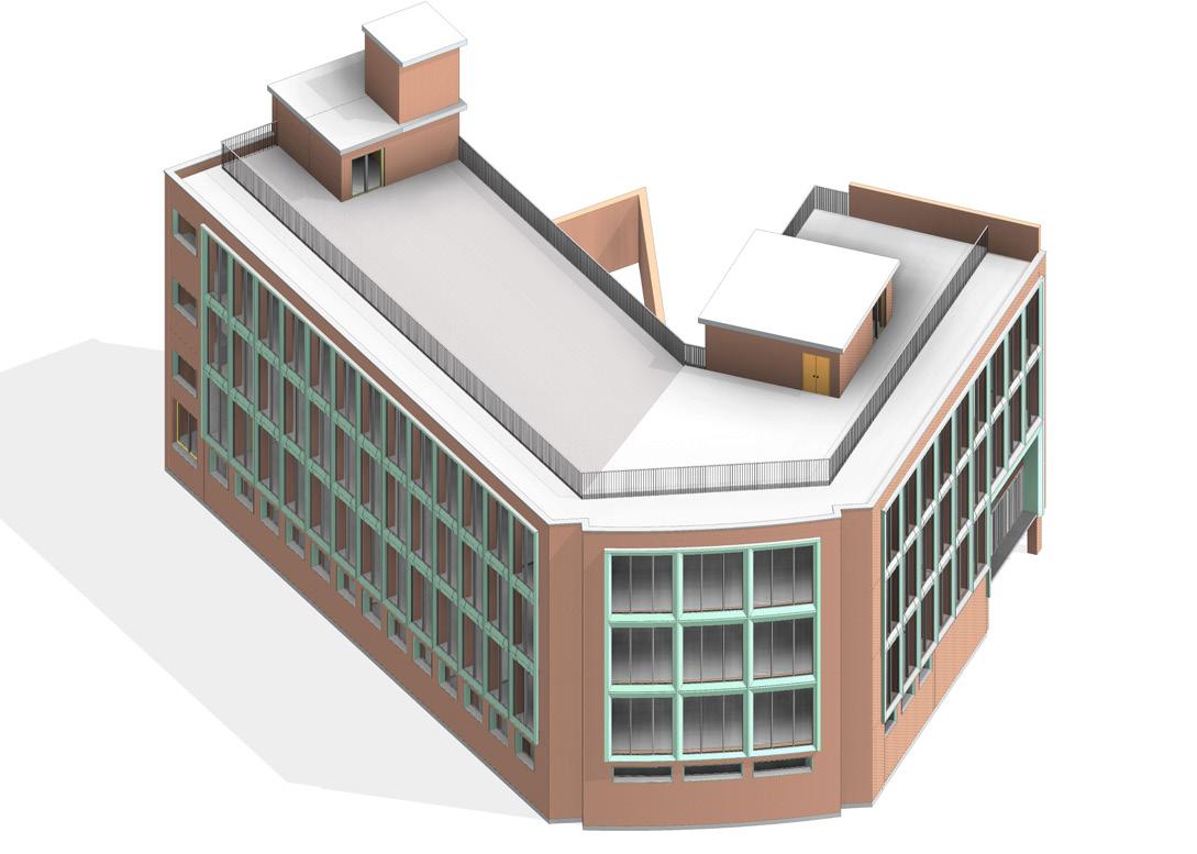
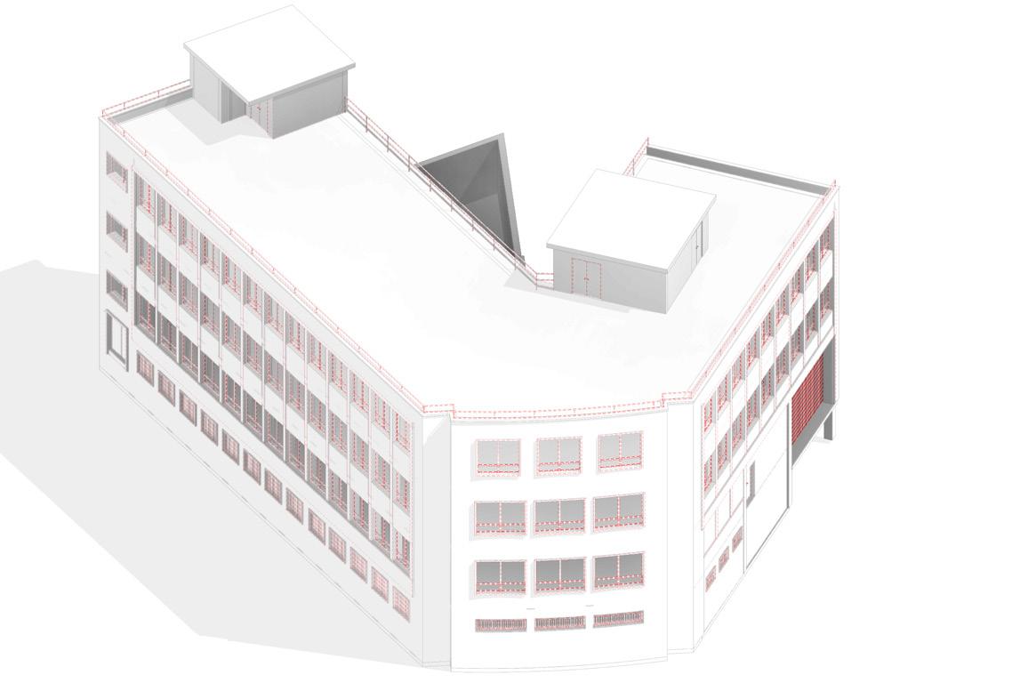
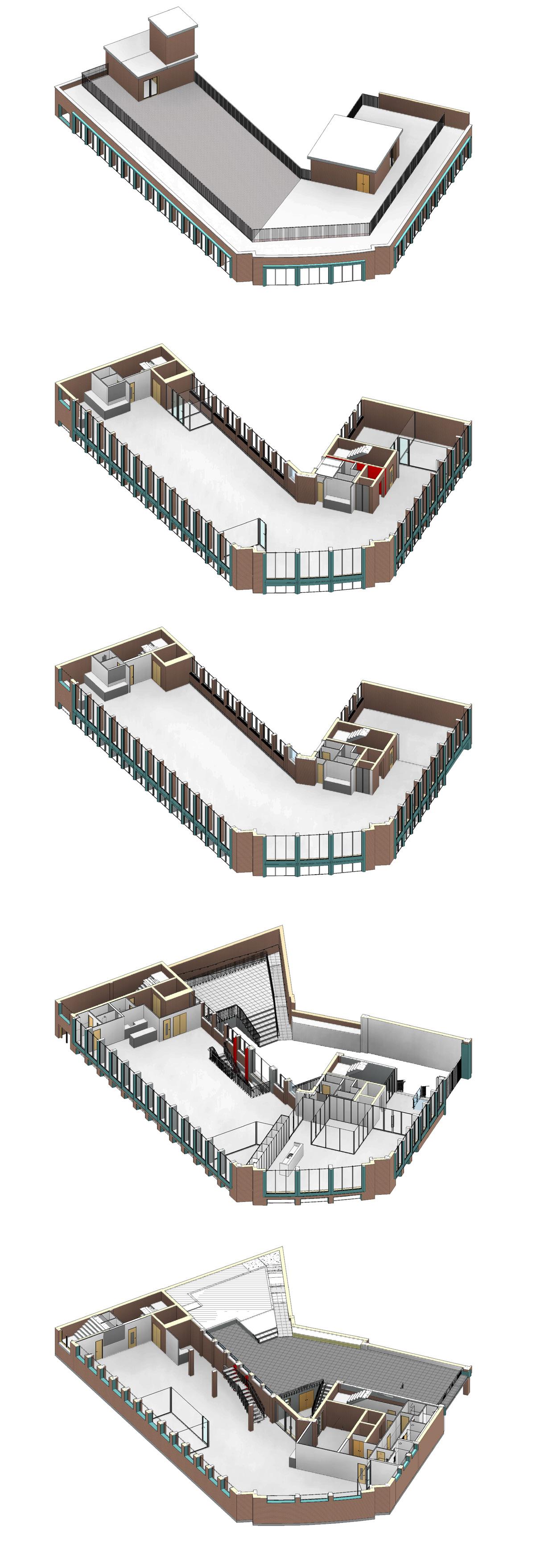
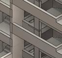
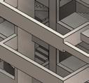
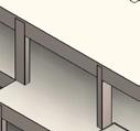
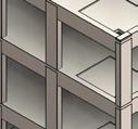
SELECTED WORK 21 PROPOSED BIM MODEL CREATED BY ME
EXISTING BIM MODEL CREATED BY ME
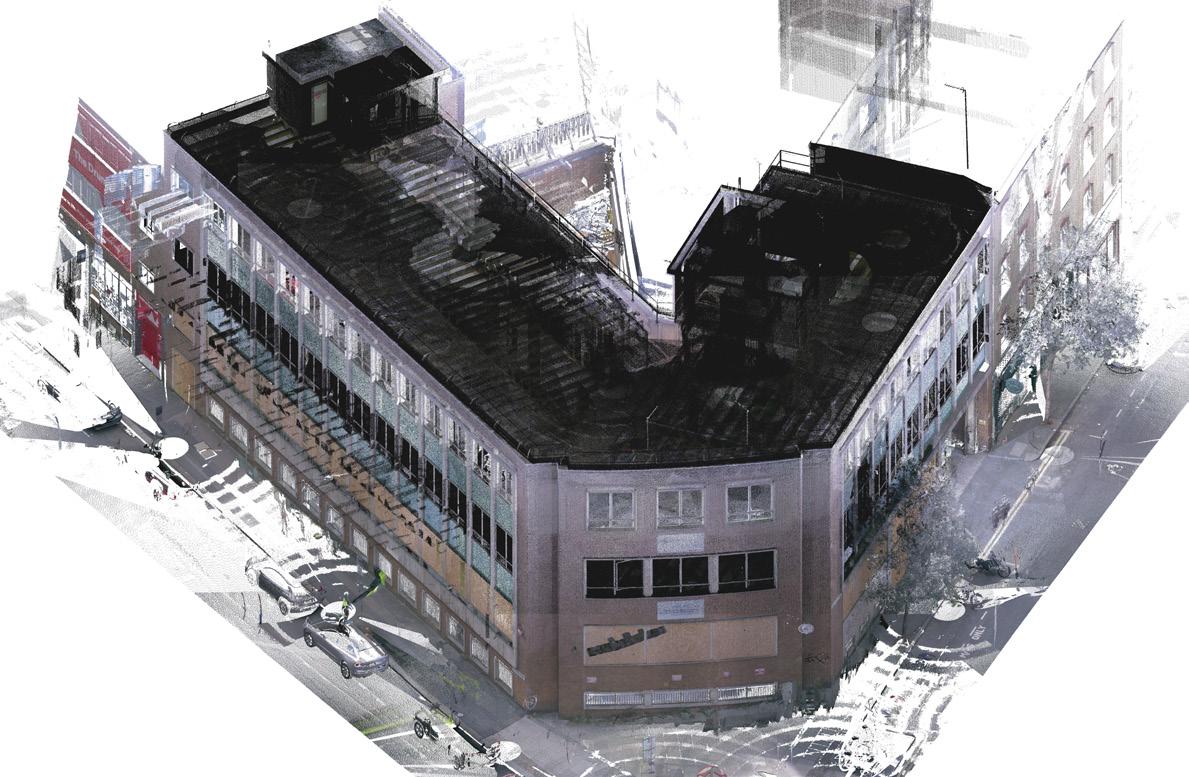
POINT CLOUD
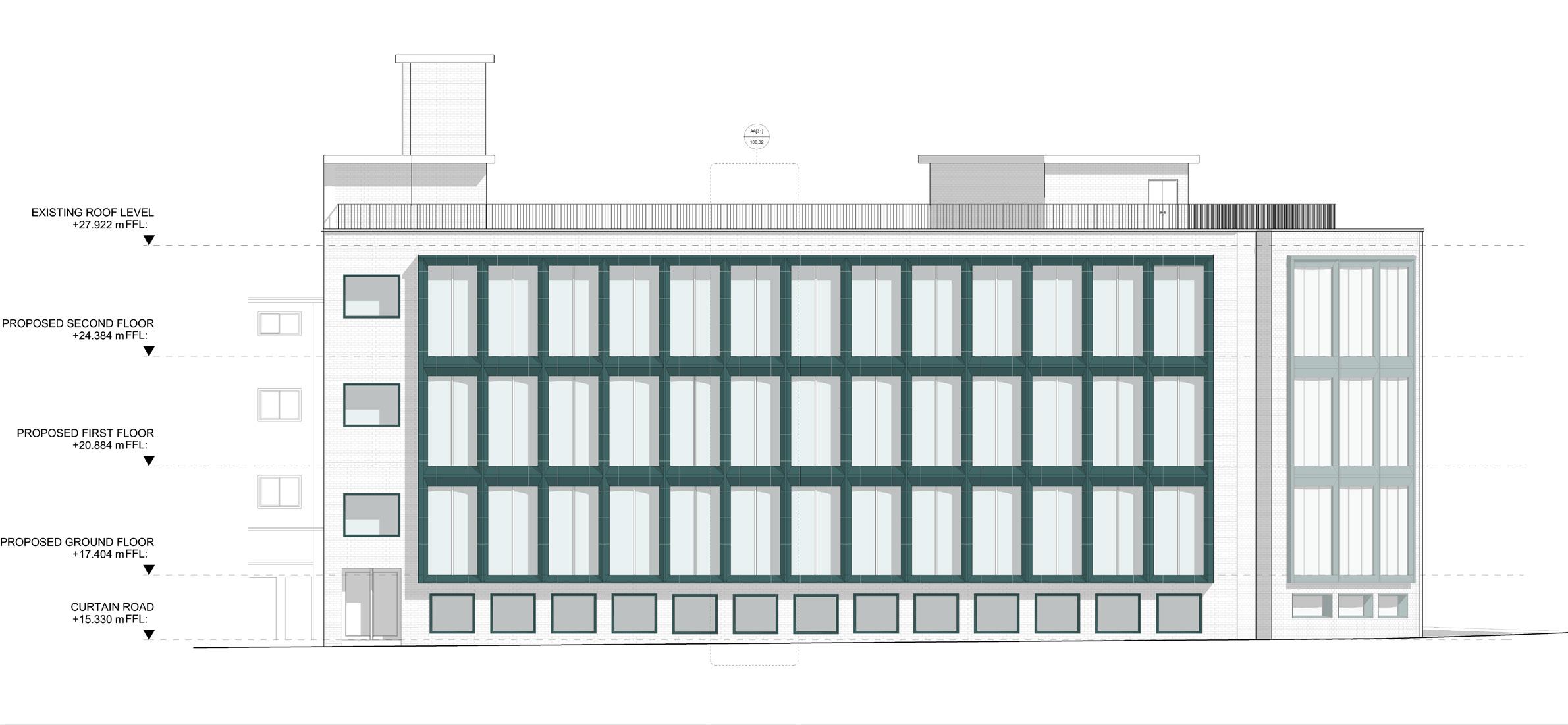
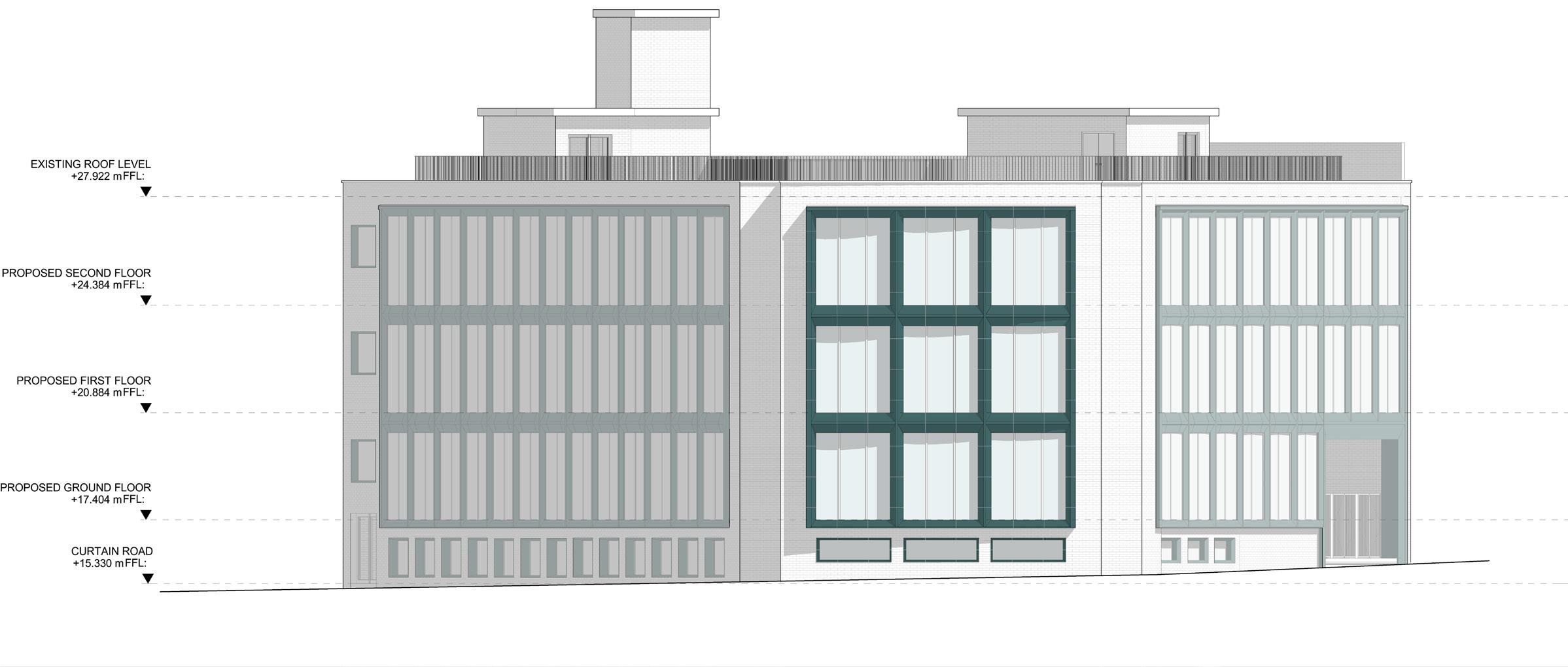
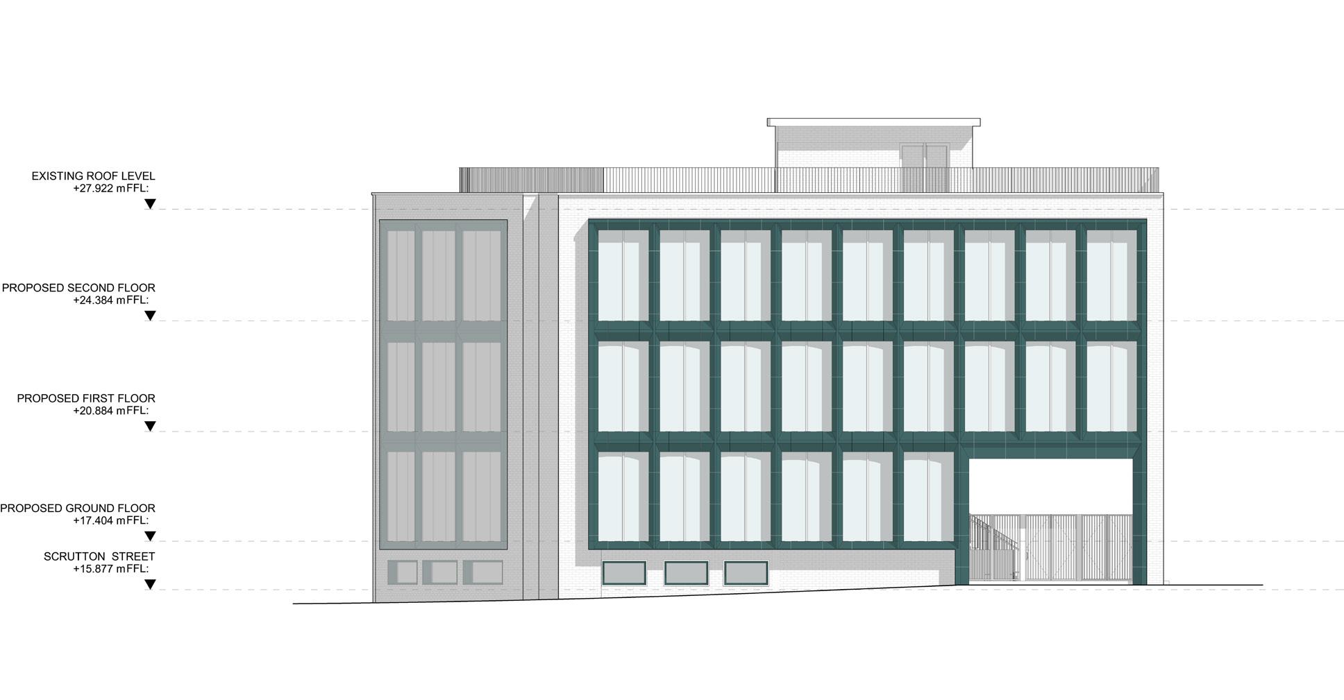
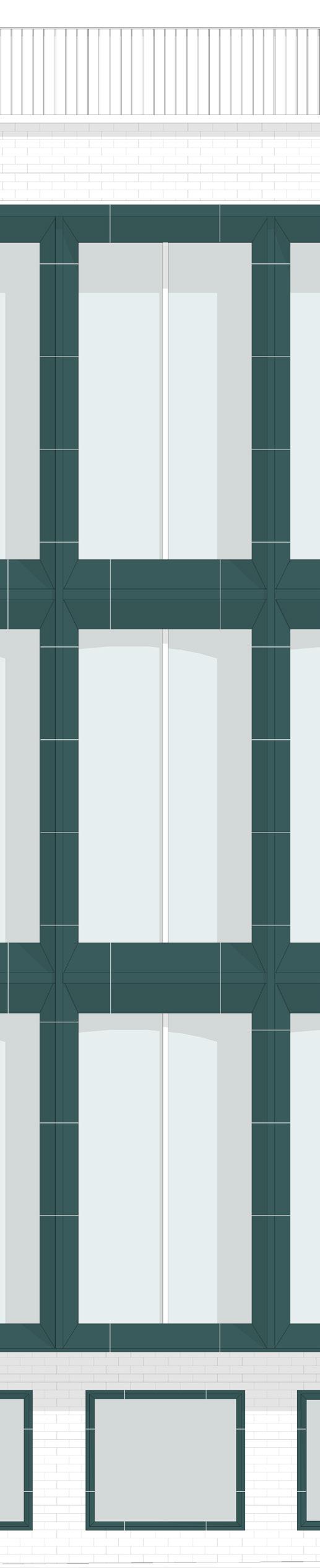
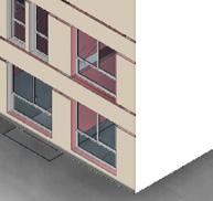
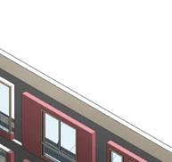
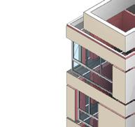
22 PROPOSED ELEVATIONS
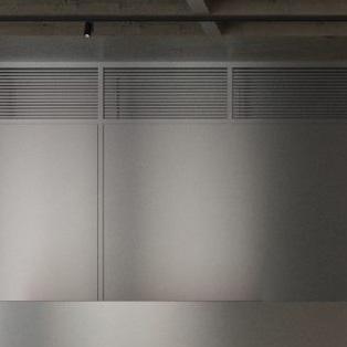
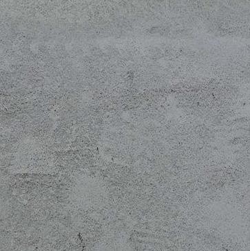
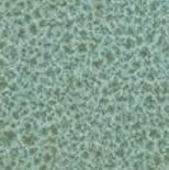
SELECTED WORK 23 STAINLESS STEEL
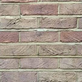
EXPOSE CONCRETE TERRACOTTA HANDMADE
CLEANING BRICKS
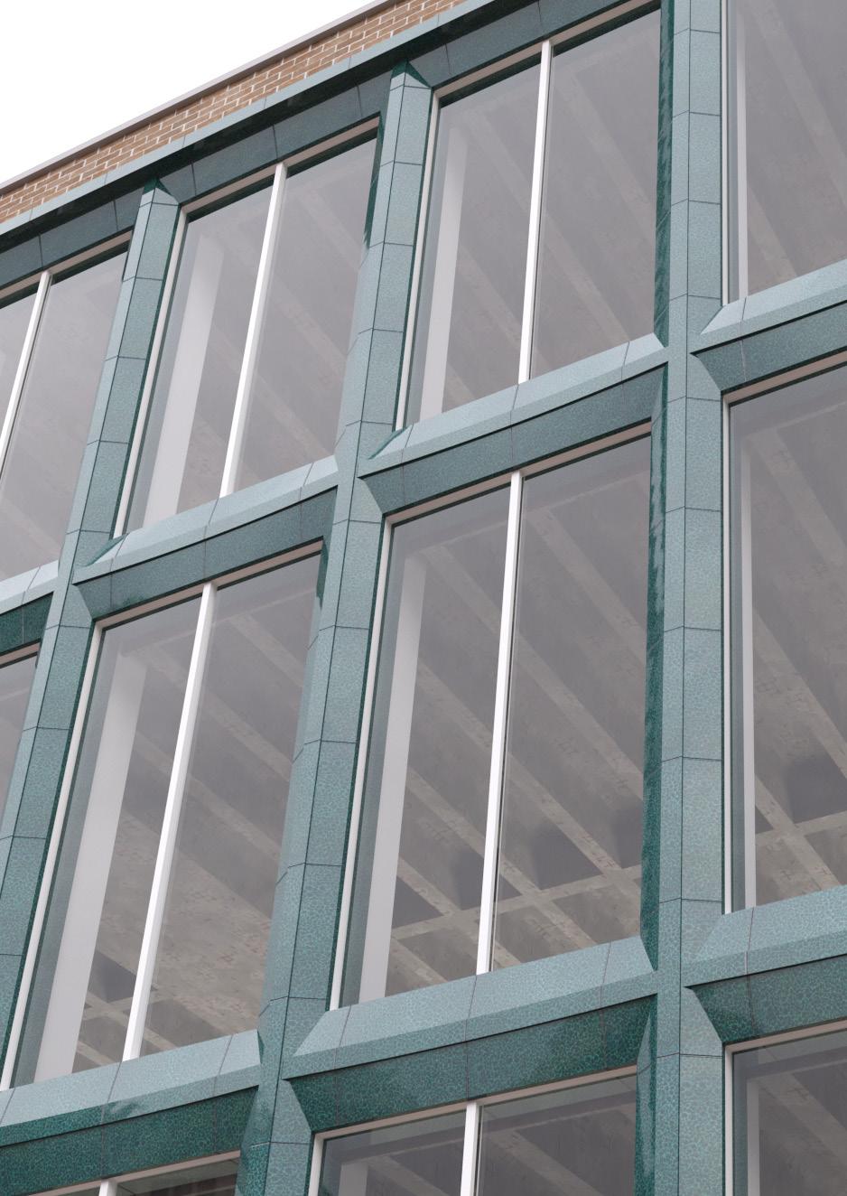
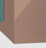
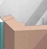
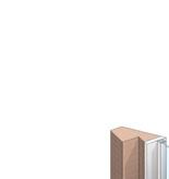
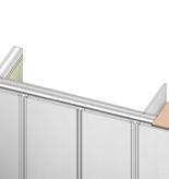
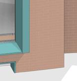
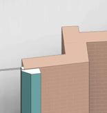
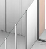
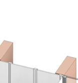
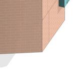
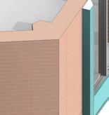
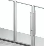
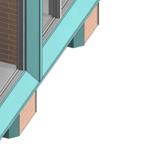
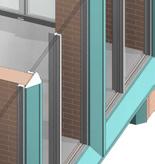
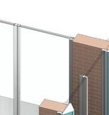
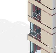
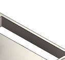
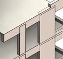
Ahmed M. Attia 24 TERRACOTTA FACADE DETAILS @JMA
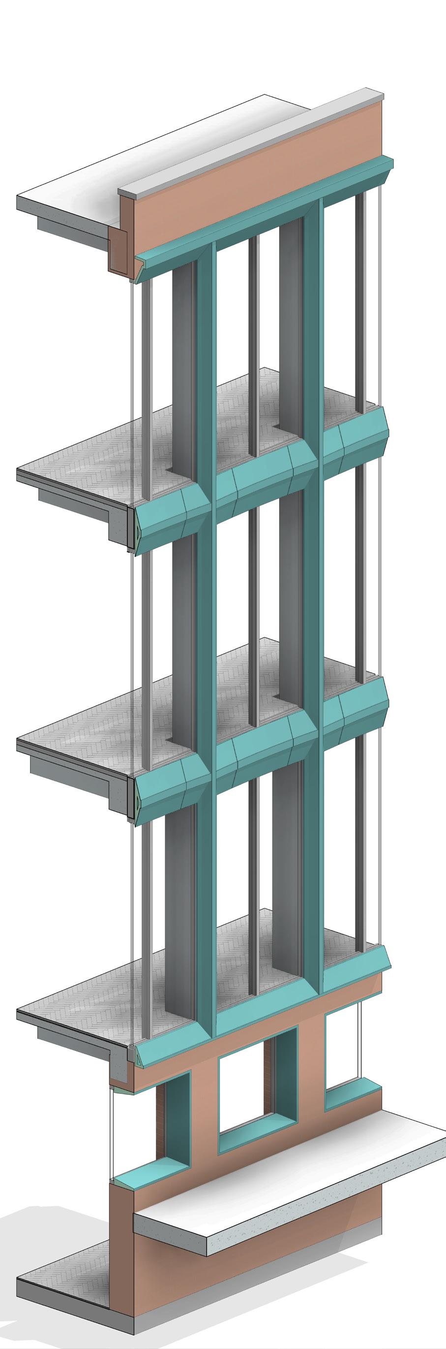
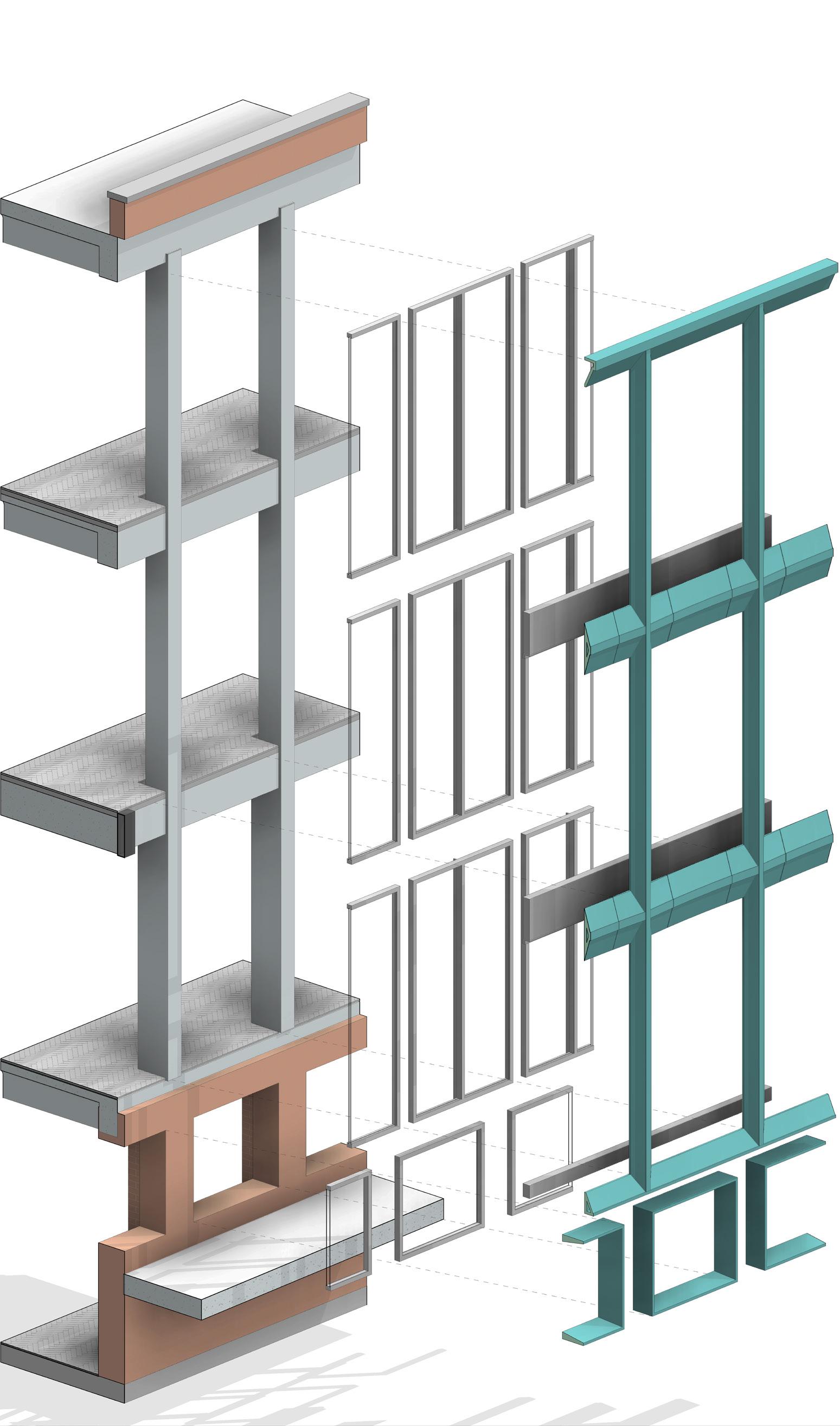
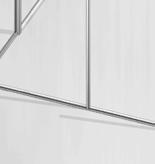
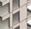
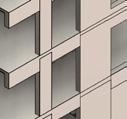
SELECTED WORK 25 FACADE DETAILS FROM BIM
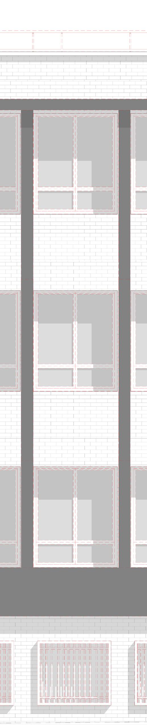
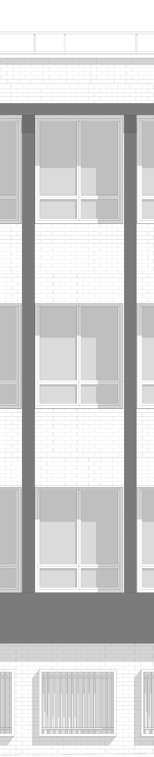
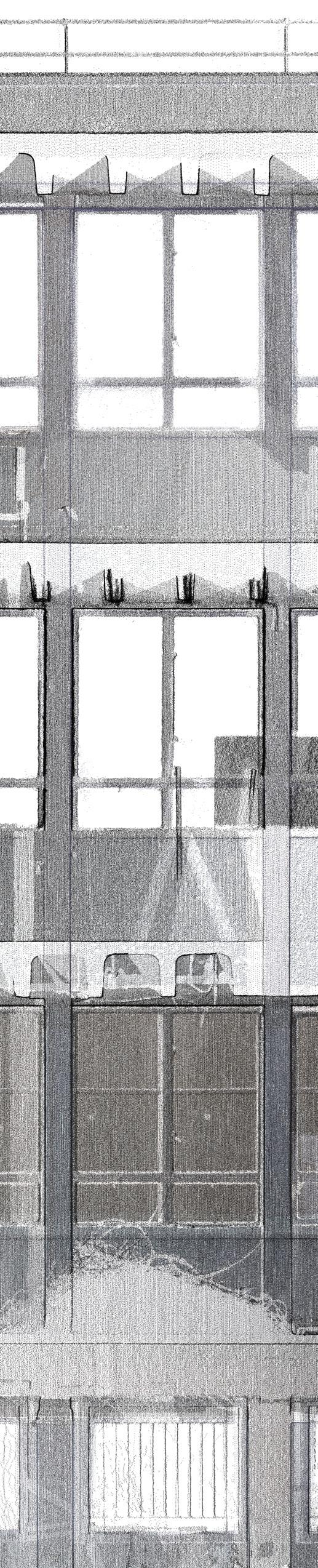
Ahmed M. Attia 26 POINT CLOUD FACADE DETAILS
EXISTING DEMOLITION PROPOSED
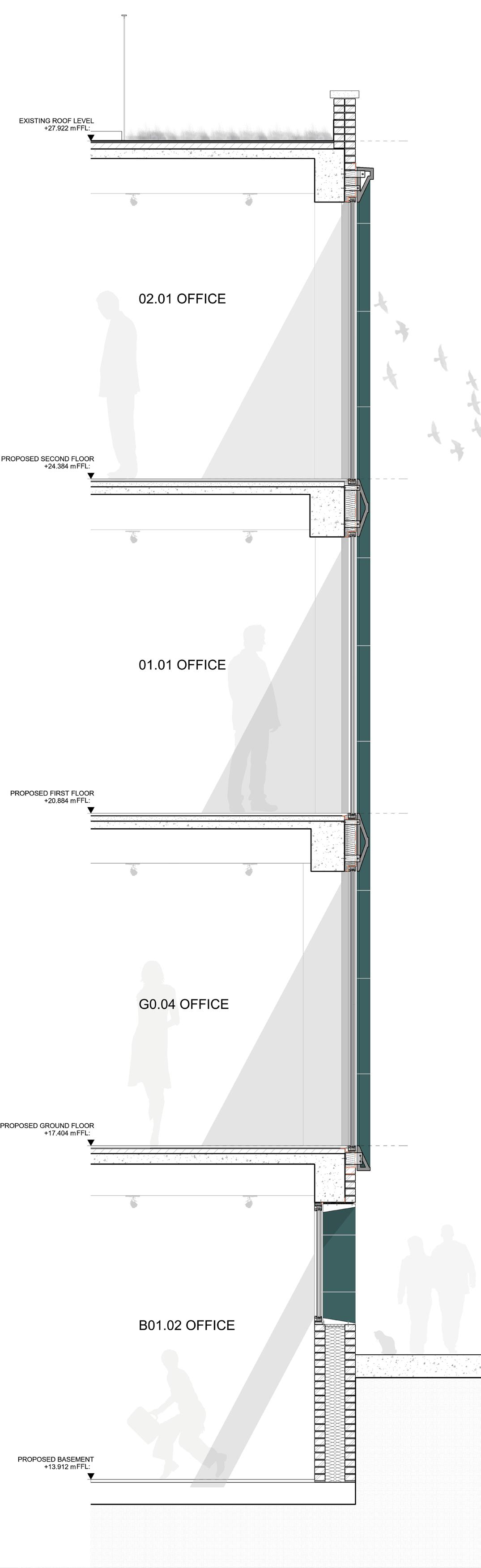


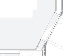
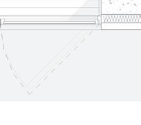
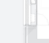
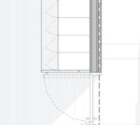
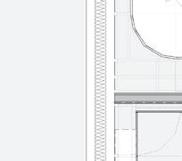
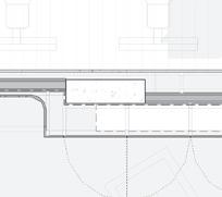
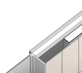
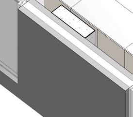
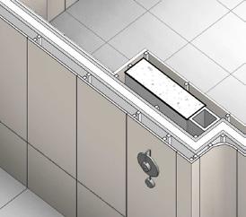
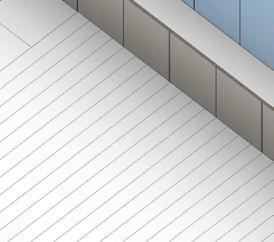
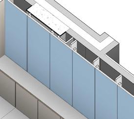
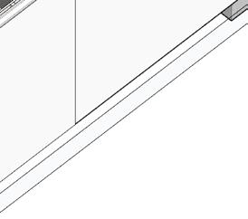
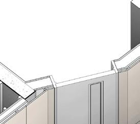
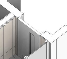
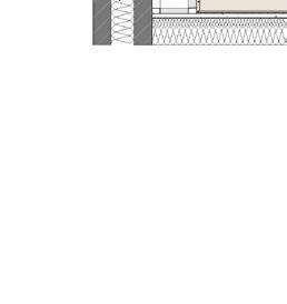
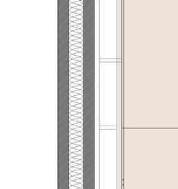
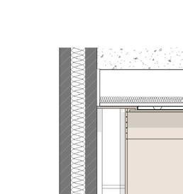
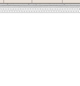
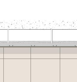
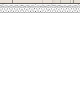
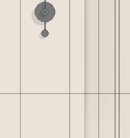
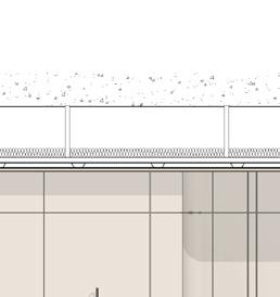
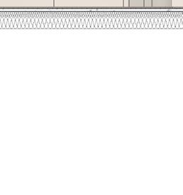
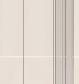
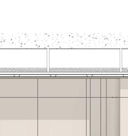
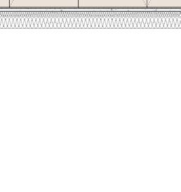
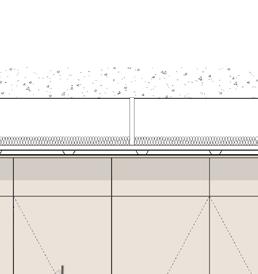
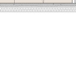
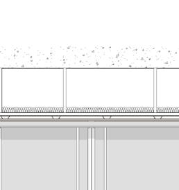
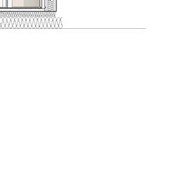
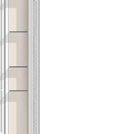
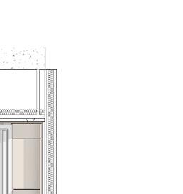
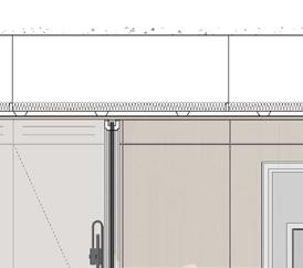
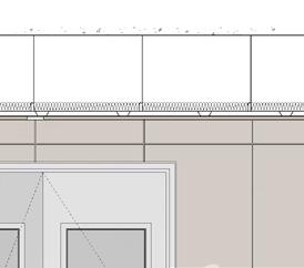
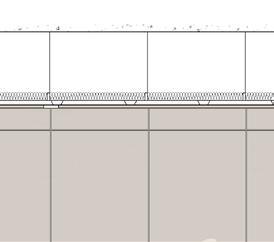
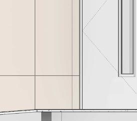
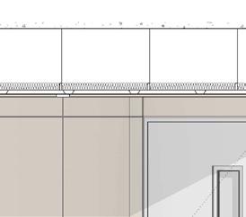
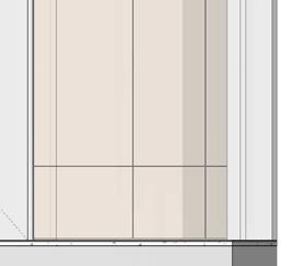
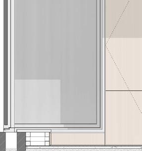
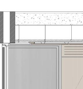
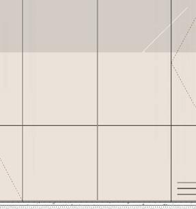
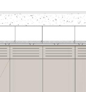
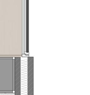
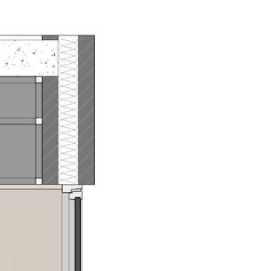
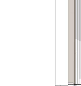
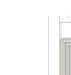
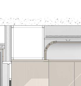
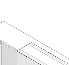
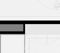
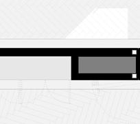
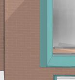
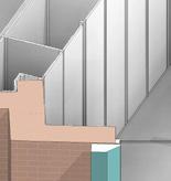
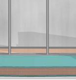
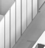
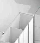
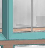
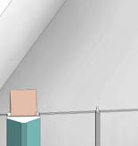
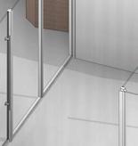
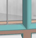
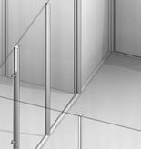
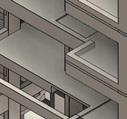
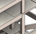
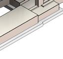
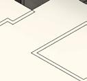
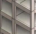
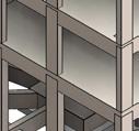
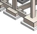
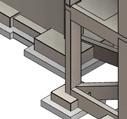
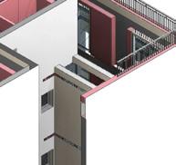
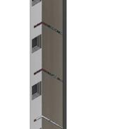
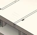
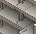
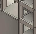
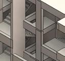
SELECTED WORK 27 FFL: EXISTING GROUND FLOOR LEVEL +17.372 m K10.154 Structure column in view M40.400 Terracotta joint L10.100.01 Schueco AWS 75 WF.SI+ K21.100 Havwood floor Existing screed C40.102 Existing downstand beam C40.102 Coffered slab in view Adhesive (K21.110), primer (K21.120) & DPM (K21.130 Structure plate Refer to SE info Mastic FFL: PROPOSED GROUND FLOOR +17.404 m M40.400 Terracotta panel K21.130 DPM Insulation L10.100 Schueco AWS 75 WF.SI+ Metal closing piece to match finish of window frame K21.100 Core expansion strip to perimeter of flooring M40.400 Terracotta panel 260 35 225 120 15 G10.100.01 Fixing frame at low-level cornice G10.201 Stainless steel bar supporting the terracotta panel FFL: EXISTING SECOND FLOOR +24.352 m M40.400 Terracotta joint side view K10.154 Structure column in view L10.100 Schueco AWS 75 WF.SI+ Existing screed C40.102 Coffered slab (in view) C40.102 Existing downstand beam The metal closing piece to close the gap from the chipping off Adhesive (K21.110), primer (K21.120) & DPM (K21.130 FFL: PROPOSED SECOND FLOOR +24.384 m K21.100 Core expansion strip to perimeter of flooring K10.154 Structure column in view L10.100.01 Middle mullion in view M40.400 Terracotta panel K21.130 DPM 5 10 252 100 252 603 40 X 40 mm Chipping off of existing lintel beam 40 G10.100.02 Fixing frame at spandrel panel G10.201 Stainless steel bar supporting the terracotta panel EXISTING ROOF LEVEL C40.101 Cleaning of existing coping stone Existing cap sheet (torch bonded) Existing x 10mm asphalt sheets (bitumen bonded) Existing screed to falls C40.102 Existing downstand beam L10.100.01 Schueco AWS 75 WF.SI+ The metal closing piece to close the gap from the hipping off K10.154 Structure column in view K21.130 DPM F30.103 Insulation L10.100 Middle mullion in view 15 40 X 40 mm Chipping off of existing lintel beam G10.100.03 Fixing frame at highG10.201 Stainless steel bar supporting the terracot FACADE DETAILS
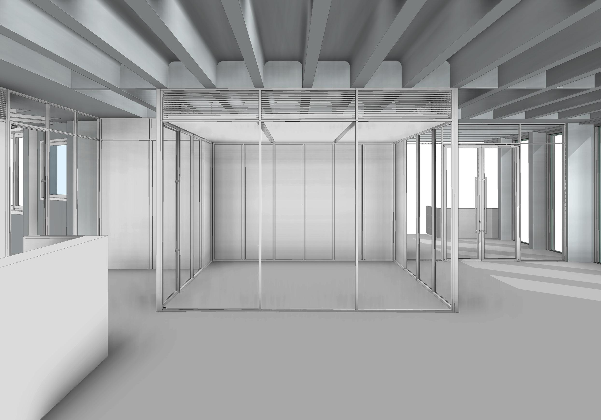
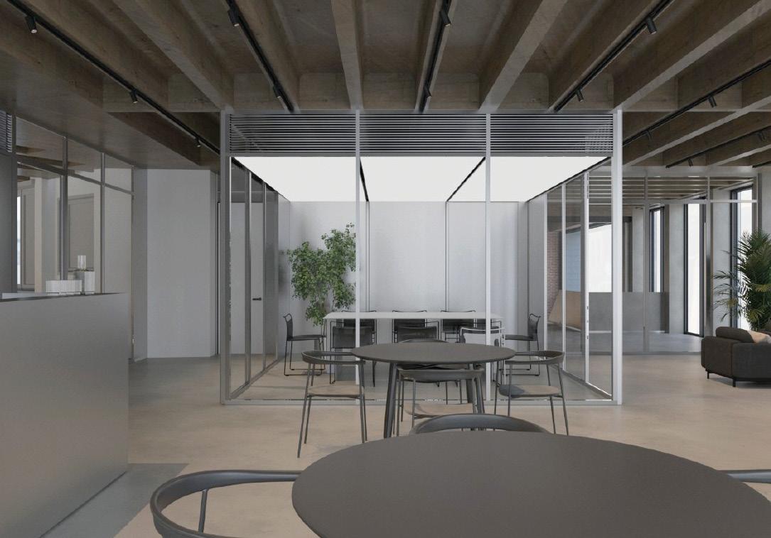
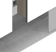
CAFE BIM MODEL CREATED BY ME
CAFE DESGIN @JMA


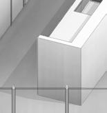

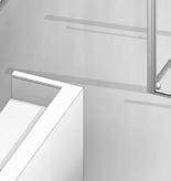


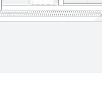
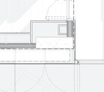
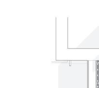
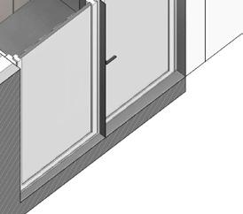
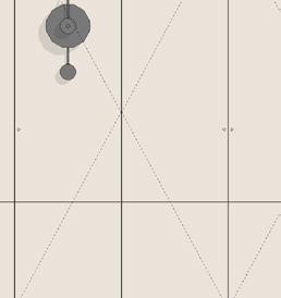
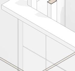
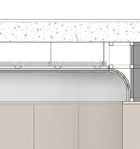
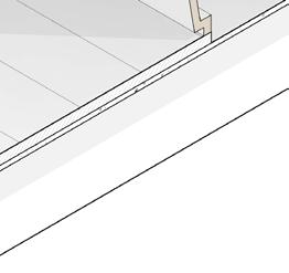
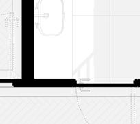
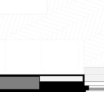
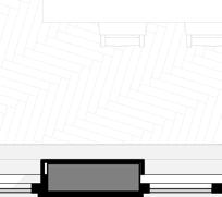
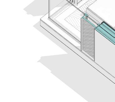
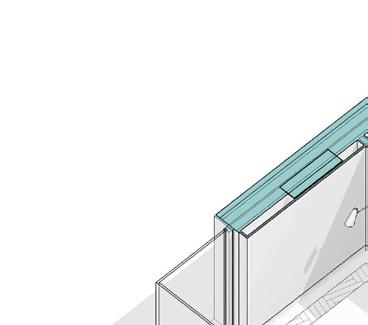
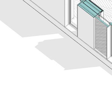
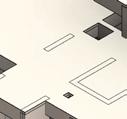
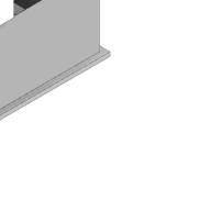
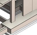
SELECTED WORK 29 CAFE ASSEMBLY CL CL CL Align Align Align Align Align FFL: PROPOSED GROUND FLOOR LEVEL +17.402 m FFL: PROPOSED FIRST FLOOR LEVEL +20.882 m L10.200 Glazed partitions at GF C40.102 Cleaning of soffit Stainless steel slatted grill L10.300 Brushed steel partitions L10.300 Brushed steel partitions N11.111 Kitchen cabinets M10.132 Screed N11.110 Bar Casework profile and bar to be aligned with the center of the coffer CL CL Align FFL: PROPOSED GROUND FLOOR LEVEL +17.402 m L10.200 Brushed steel slatted grill C40.102 Cleaning of soffit N11.111 Kitchen cabinets L20.101 Brushed steel doors L10.200 Glazed partitions at GF L20.102 Glazed doors at GF K10.154 Exposed concrete Vertical mullion to be centered on concrete ridge/downstand.
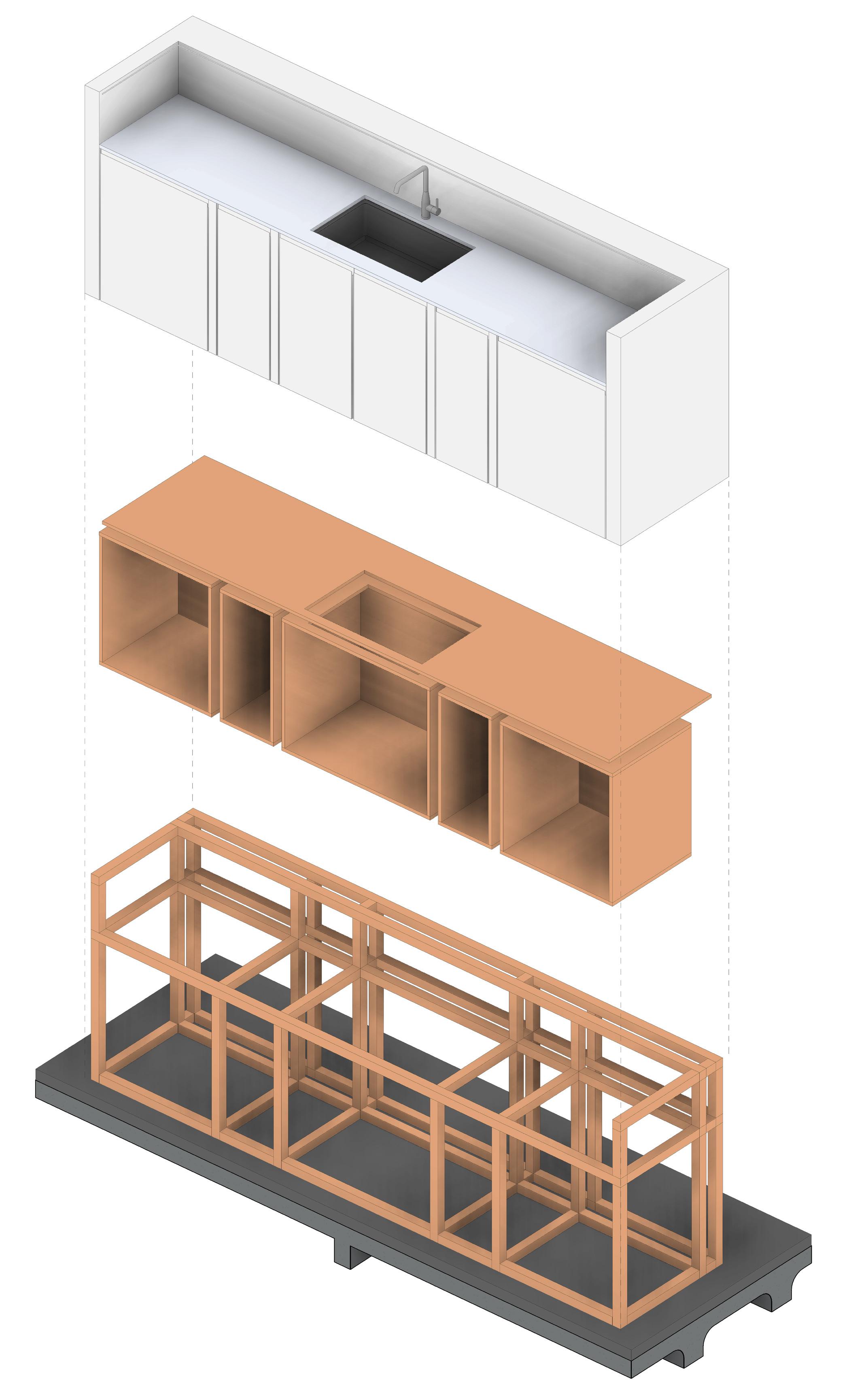
Ahmed M. Attia 30 BAR ASSEMBLY
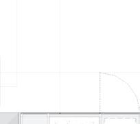
SELECTED WORK 31 CL FFL: PROPOSED GROUND FLOOR LEVEL +17.402 m N11.110 Bar M10.132 Screed 3378 10 N11.110 Large format stainless steel sheets bonded to ply and fixed back to timber frame. CL FFL: PROPOSED GROUND FLOOR LEVEL +17.402 m N11.203 Fully integrated fridge N11.200 Kitchen sink N11.201 Kitchen mixer N11.202 Fully integrated dishwasher 300 900 870 10 eq2. eq3. 3378 Sink and mixer centered of the kitchen units N11.110 Top made of MDF coated with brushed steel plate 20 10 Space for bins as specified in N11.110 eq1. eq3. eq2. eq1. FFL: EXISTING GROUND FLOOR LEVEL +17.372 m FFL: PROPOSED GROUND FLOOR +17.404 m CL FFL: PROPOSED GROUND FLOOR LEVEL +17.402 m Double sockets N11.203 Fully integrated fridge N11.110 Top made of MDF coated with brushed steel plate N11.200 Kitchen sink N11.201 Kitchen mixer N11.202 Fully integrated dishwasher eq1. 718 eq2. eq3. eq3. eq2. eq1. N11.201 Kitchen mixer N11.200 Kitchen sink N11.110 Large format stainless steel sheets bonded to ply and fixed back to timber frame. N11.110 Large format stainless steel sheets bonded to ply and fixed back to timber frame. N11.110 Top made of MDF coated with brushed steel plate N11.110 Top made of MDF coated with brushed steel plate N11.110 Large format stainless steel sheets bonded to ply and fixed back to timber frame. M10.132 Screed 793 558 581
@ORASCOME DEVELOPMENT
OWEST
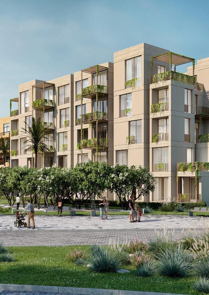
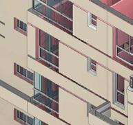
RESIDNTIAL BUILDINGS
YEAR : 2023
LOCATION : 6 OCTOBER, EGYPT
TOTAL AREA: 200 SQM per type
OWNER: ORASCOM DEVELOPMENT
PROJECT DESCRIPTION:
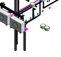
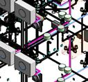
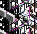
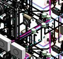
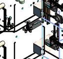
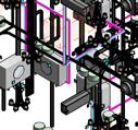
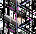
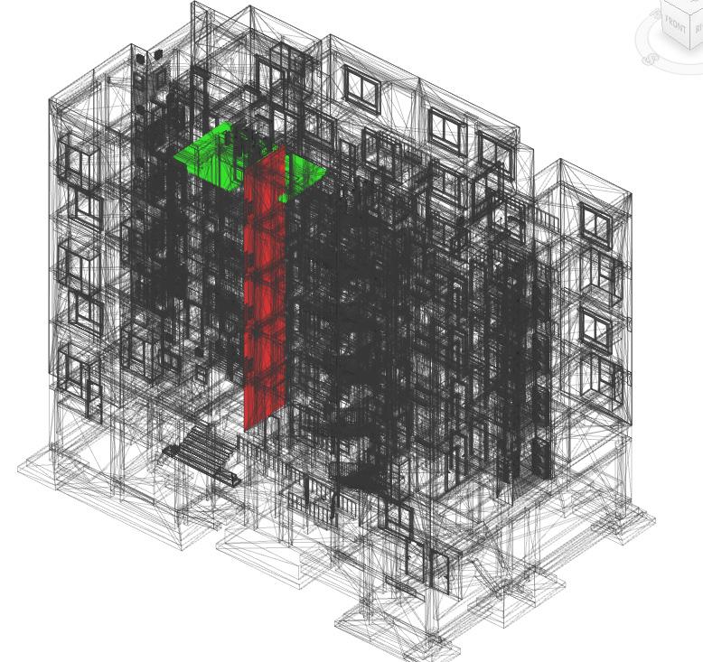
The project involved creating BIM models for a residential district in the Owest City. With over 10 blocks, each block featured at least six different types, with floor areas exceeding 2000 sqm. The goal was to enhance collaboration and clash detection among disciplines using BIM technology. The office team designed and implemented the detailed BIM models, encompassing architectural, structural, electrical, mechanical, and plumbing elements. Clash detection analyses were conducted to identify conflicts, aiding in efficient resolution. The project aimed to improve efficiency, minimize errors, and deliver high-quality residential blocks within the Owest City.
MY SCOPE OF WORK:
• Detailed 3D BIM Model Creation: Developed a comprehensive BIM model with architectural, structural, and MEP elements.
• Design Review: We enhanced the main design provided by the main consultant to ensure compliance with building regulations.
• Clash Detection and Coordination: Identified and resolved clashes, coordinating with stakeholders such as engineers and consultants.ment activities, obtaining quotes, and reviewing specifications.
SELECTED WORK 33
All level & grids created via dynamo.
EXTERNAL MODEL
INTERNAL MODEL SHEET

All cad files to be link with the GHOST bim model


BIM CAD DATA FD STR MODEL


ARCHITECTURE -CAD Drawings -Master Plan -Basement -Arch drawings -Str drawings -MEP drawings CDE Folder IN 1. Template 2. Library 3. Title block 4. 3D modeling Checklist 5. Software Version 6. Naming convention -Models - Drawings - .. etc CDE Folder, Shared ,Project Standards
Ahmed M. Attia 34 CLIENT DELIVERABLES GENERAL PROCESS MAP & MODEL SEGREGATION OW-KT-1B3-BLK6-H-M3-A-GH-S0 FD ARCH MODEL OW-KT-1B3-BLK6-H-M3-A-EX-S0 OW-KT-1B3-BLK6-H-M3-A-ID-S0 OW-KT-1B3-BLK6-H-M3-A-SH-S0
LEVELS & GRIDS GHOST


SELECTED WORK 35 SHEET
OW-KT-1B3-BLK6-H-M3-A-FD-S0
OW-KT-1B3-BLK6-H-M3-A-EX-S0
OW-KT-1B3-BLK6-H-M3-A-EX-S0
CLASH REPORT STR MODEL MEP MODELS NWD RFIs FEDERATED MODEL STRUCTURE
COORDINATION CLOUD BIM 360 FD MEP MODEL NWD MODEL
OW-KT-1B3-BLK6-H-M3-A-EX-S0
& MEP

Ahmed M. Attia 36
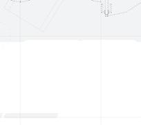
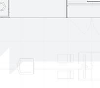
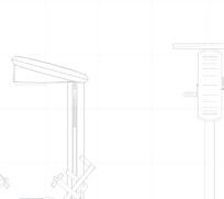
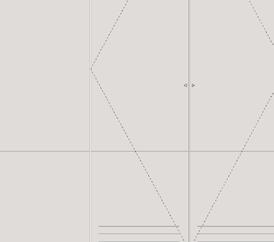
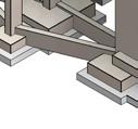
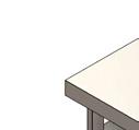
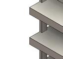
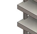
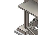
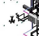
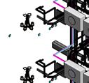
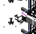
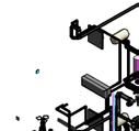
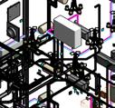
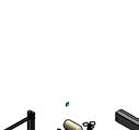
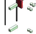
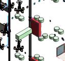
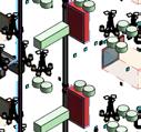
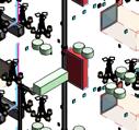
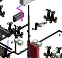
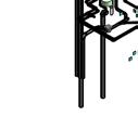
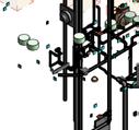
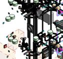
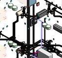
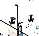
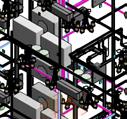
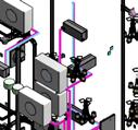
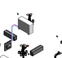
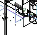
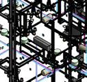
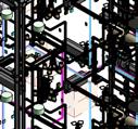
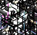
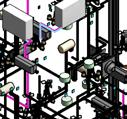
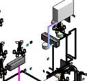
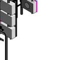
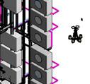
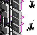
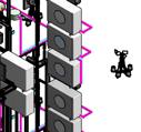
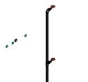
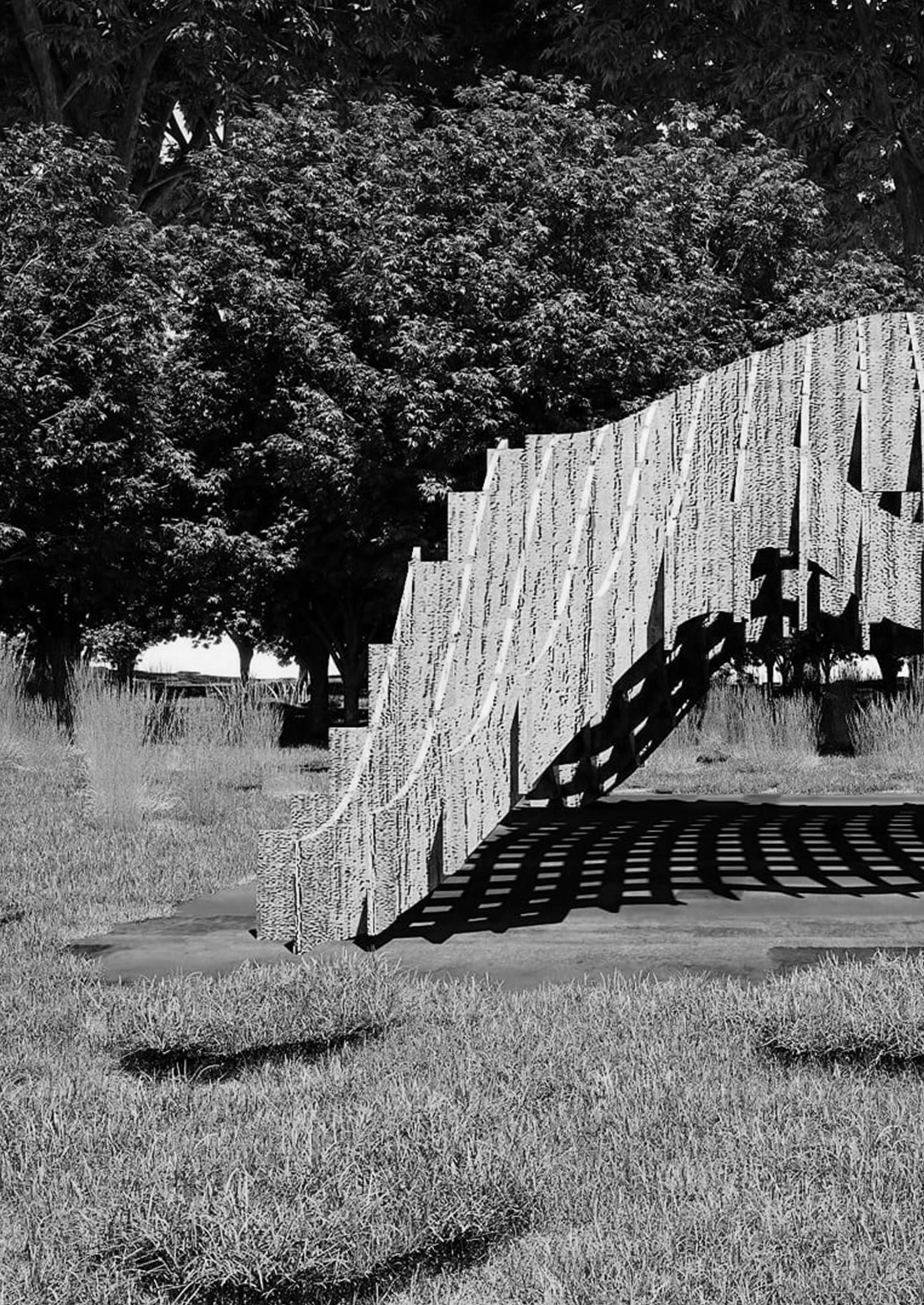
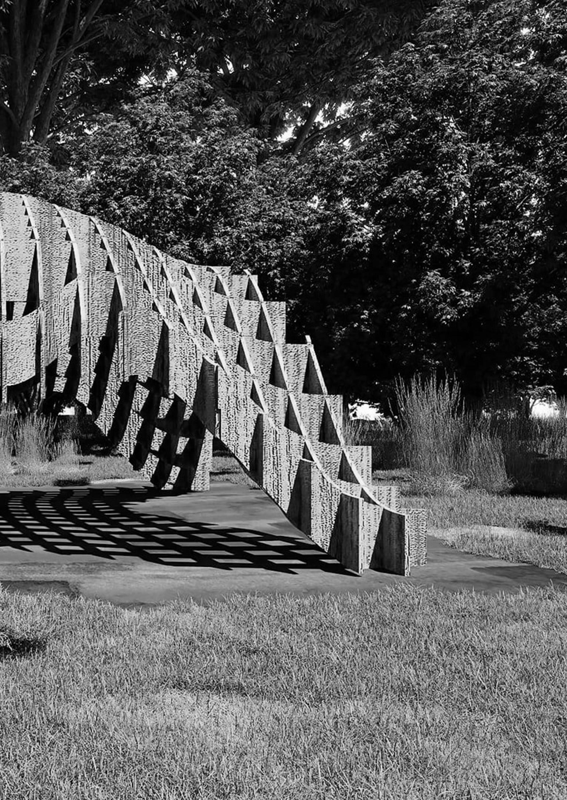
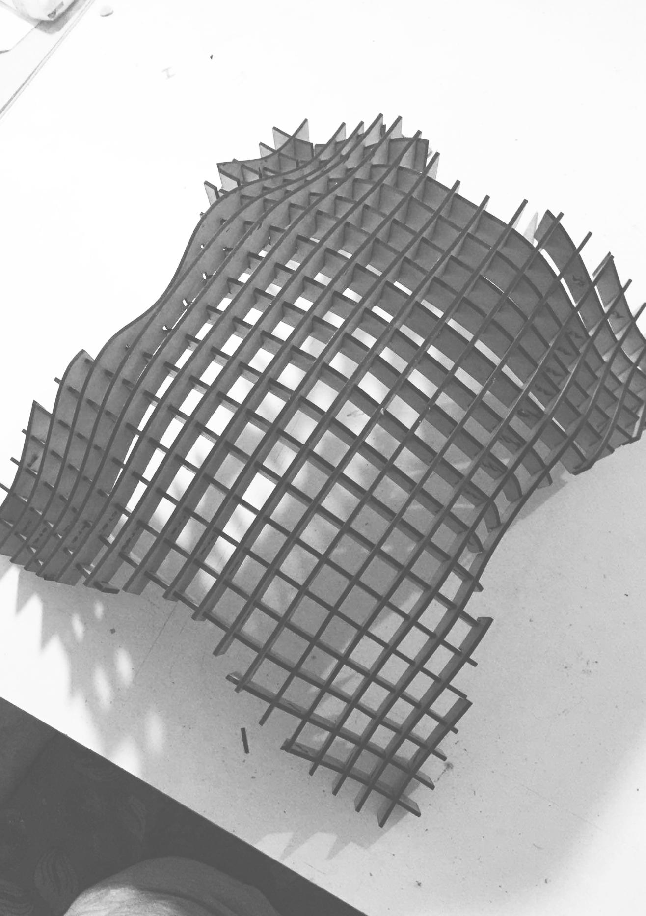
X SPIDER COMPUTATIONAL PROJECT
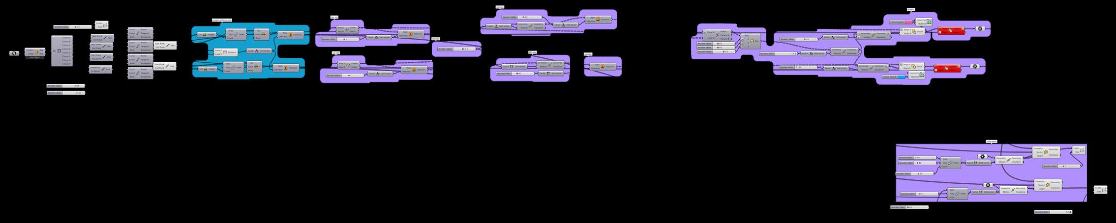
PROJECT DESCRIPTION:
This is an advanced way of doing waffle structure with computational design via rhino and grasshopper .In the beginning, it was necessary to divide an organic surface into two axis on the x-axis and y-a is To crate points on these two axis and connect between those points to form the grid basis. For cutting the r quired surface These divisions are transformed into curves on the surface and derived frocross-section . After that we work the joints between intersections to form this shape.
SELECTED WORK 37

FEEDBACKS
“We have been working with Ahmed for a while and he helped us deliver multiple projects on various stages and levels of complexity. He was always easy to work with, professional and delivered the highest quality output 100% of the time. Ahmed also proved to be a fast learner and quickly adapted to our internal processes and quality standards. I can highly recommend using his services if you are looking for anything Revit-related, architectural designs or renders. Thanks Ahmed! ”
Korneliusz Krupa, CO-FOUNDER VersPro ltd, UK (UPOWRK)
“Excellent!”
JOE MILIES , FOUNDER JOE MILIES ARCHITECT ltd, UK (UPOWRK)
Ahmed M. Attia 42


