


Function. urban rennovation (1st phase) / Educational building (2nd phase).
Location. District VIII (VIII. kerulet), Budapest, Hungary Area. 5100 m2


Project description. NEO Architecture School of Crafts is a visionary institution that embodies sustainability and community integration. One of its key features is a state-of-the-art ventilation system, designed to minimize energy consumption and promote a healthy indoor environment. The school's urban concept revolves around connecting the inner courtyard of the building with the surrounding community, fostering interaction and engagement. Additionally, the school takes a collaborative approach by involving residents of the nearby Josevaros residence in the learning methods of crafts. This inclusive approach not only
enhances the educational experience but also strengthens the bond between the school and the community, creating a vibrant and sustainable learning environment.
Functional program.

Educational Facilities: The project includes two masses of educational facilities, such as classrooms, laboratories, workshops, and administrative areas.
Gathering Terraces Bridge: A bridge connects the two masses of educational facilities and incorporates gathering terraces for informal interactions and collaboration.
Open Spaces: Courtyards, plazas, and green areas are integrated into the design, providing outdoor learning and socialization spaces.
Multi-View Classrooms: Innovative classrooms offer multiple views of the surrounding landscape, promoting a holistic learning experience.
Flexible Spaces: The design includes adaptable spaces that can be reconfigured for various educational activities such as lectures, workshops, and exhibitions. ground floor.
- manger room
- adminstrative offices
- adminstrative management offices
- entrance lobby
- cloakroom
- cctv
- patio gardens
- w.c
- teqnical rooms
- storage zone
- gallery hall
repeted floor (1st ,2nd).
- manger room
- adminstrative offices
- adminstrative management offices
- classrooms
- workshops
- shared terrace
- patio gardens
- w.c
- seminar
- storage zone
- class hall
urb/bme Arct1itect Ahmad Aldebsi Faculty ofArchitecture Project BUDAPEST UNIVERSITY OF TECHNOLOGY AND ECONOMICS NEO
�.
,ekas Mihaly � 18nos 9 9 orczy Alkatresz Aruhaz O ' ,.,,ossu 9 'i ;,am MuzsiRus ciganyok parkja 9 ' �\ Pazmany Peter Katolikus Egyetem 1nformac16s Losonc, t;f f G6lya Pres
"' Pr.iteru · f 111-" lurger-Bar-Hol T .... l,/ Pnm est K T . 1sino
•
•·,
· ·,.
.. '
(/) .,/: ,. l:.\Hedon 0 , ii Semmelweis Egyetem YOohany g Balassa Janos Kolleg,um � ft "" c: T1ombu i
1ikak Gy6gyszertar
C MagyarQTermeszettudoma,oyl'. T
-
lillOiut Nemzet KOz.s£�1galat1�
Jw1emT
P.02 1m 4m 2m
PROJECT DESCRIPTION 47°29'12.1"N 19°05'13.3"E (!) A
1 . Theprojectplotis situatedadJacent tobotha transportationpath anda pedestrian path. The key conceptbehind shaping theplotrevolves around establishingaseamless connection betweenthe externalandinternal spacesthroughapedestrianaxis.


2. In theformfinding process, careful consideration isgiven todetermine the optimalvolume requiredforthebuilding toeffectively accommodate the functionalprogram whileensuring seamless integration.


3. Anew public plaza willbeestablished in District 8, making use of theschool'scourtyard toprovideavibrantgatheringspaceforthecommunity.
'----similar projects
case study. Duringmyrecent visitto District 8, itbecameevident thatthe mu
nicipality was putting tremendous effort intotransforming thearea intoa more appealing and vibrant place. Their focus was primarily on improvingthe quality oflife
for local residents while alsoattractingforeign investmentfornewprojects. Notably,
f therenovation of publicplazas stood outas aremarkableinitiative. Itwas in these rejuvenated spaces that Ifound inspirationformyproject, aimingtocreate abetter environment for connecting peoplefromdifferent walksoflife.The vision wastodevelopa plotthatwouldserve as ahub, fostering social interactions and inclusivity amongindividualsofdiversebackgrounds. Byemulatingthemunicipality'ssuccessfulrevitalizationefforts, I aimed tocontribute to the community's overallenhancement.
urb/bme Arct1itect Ahmad Aldebsi Faculty ofArchitecture BUDAPEST UNIVERSITY OF TECHNOLOGY AND ECONOMICS Project NEO P.03
1 bauhause school 3.folding park 2.Aarhus School ofArchitecture •�! === == . TI' ,._ I �· a...··,..r......D......T1•
.· ..
� ·
1m 4m 2m
GROUND FLOOR/ PLAN -3D SECTION 47°29'12.1"N19°05'13.3"E (!)
Road map. A roadmaphighlightstheprimary thoroughfares within J6zsefvaros and illustrates theirconnectivity totheproject site, showcasingthenetworkofroads and their links tofacilitatenavigation and transportation.

Green map.
Agreen map provides avisual representation ofthe distribution andproportion of vegetation in thedistrictof J6zsefvaros, displaying howgreenery isdispersedthroughoutthearea.
MassNoid map.
Amass/voidmapvisuallypresentsthedensitydistribution within J6zsefvaros, comparing ittothe green mapand showcasing theheights ofbuildingsin ordertohighlightthethoughtfulplanning andbalancebetweenbuilt-up areasandopen spacesin the district.
Solar study map. providesan analysisofthe solar potentialin J6zsefvaros, displaying thedistribution ofsunlight exposurein relation to the green map andindicating theheightsofbuildings.Thiscomprehensive analysis showcases how wellthedistricthas been planned in termsof maximizing solar access andintegrating sustainable energy solutions.

urb/bme P.04 Arct1itect Ahmad
1m 4m 2m Faculty ofArchitecture Project BUDAPEST UNIVERSITY OF TECHNOLOGY AND ECONOMICS NEO urban case study
Aldebsi
47°29'12.1"N 19°05'13.3"E (!)
under construction residential building
pedestrain axis was dsigned to link the inner plaza of the site with outside pedestrair1 axis
A new public plaza is created � religous building ,� churche ' public services brulding residential building


urb/bme P.05 Arct1itect
Ahmad Aldebsi
1m 4m 2m Faculty ofArchitecture Project BUDAPEST UNIVERSITY OF TECHNOLOGY AND ECONOMICS NEO •
URBAN CASE STUDY AND FORM FINDING 47°29'12.1"N 19°05'13.3"E (!)


urb/bme A P.06 Arct1itect Faculty of Architecture Project Ahmad Aldebsi BUDAPEST UNIVERSITY OF TECHNOLOGY AND ECONOMICS NEO Class rooms building main lobby walk through! axis
workstlO�PSbuilding main lobby public garden s, D, E ' F iG I 5040 960 J 240 t 960 960 1m....,_,.__..... 4m GROUND FLOOR/ PLAN - 3D SECTION 2m J I 35 34m' �4Sm' 37 50m' 38 Sim' �Slm' �84m' 41 86m' 42 91m' 43 92m' Le�l2 Level:, ciassroorn �dmln.stra cl;issroorn storage �a�:�,11 I workshops 19 20.88m' 28 24.47m1 40 34.18m' 33 80.96m' 30 82.16m' 31 82.16m' 32 83.69m' 39 110.45m' 34 121.41m' 35 125.0�m' 41 125.08m' 36 205.Hm' 27 210.63m' 38 222.87m' 37 223.48m' I I ---El----l-,2] gas boiler 56m' heating pla I 1' 3 4 10, 11, 47°29'12,1"N 19°05'13,3''E (!)
:.,....��f'fftP'�'-+-''tb-.;'r7,.,_--7"'--


urb/bme Arct1itect Ahmad Aldebsi Faculty ofArchitecture BUDAPEST UNIVERSITY OF TECHNOLOGY AND ECONOMICS Project NEO P.07 �IP,'!!:Z--.,,.-wor kshop doubleview and ventelationsystem D Dc1assUm I '"; 1111 cJ I� 240 7 / patio garden 5040 Ill 111111 11111111111 �.,._, 240 J c'1imney W.C 52.89m' 1220.88m' 19 20.88m' 623.95m' 2224. 42m' ll24.8 1 18 23,7 4m' amry 15 25.8 3m' Le,ell Levell dropp;nga, �atlngpla Level l cioakroorn storaee heatingpl3 manager« 17 36.9 4m' 14 39. 4m' 26 42.66m' 458.27m' 16 71.23m 772.56m' 25 76.69m' 20 79.16m' l0 81.28m 1 23 86.56m' gasboiler 310 3.67m' psboiler gallarey lobbyand< lobbyJOd( ,-rn 400� 9H4.69m' 21 136.09m' 8199.9 4m' 24 316. 30m' 42787.SSm� 43 927.7 3' ,__L -----1.__ ��- ---+=-= C1 1m....,_,.__..... 4m FIRST FLOOR/ PLAN -3D SECTION 2m 47°29'12.1"N 19°05'13.3"E (!)


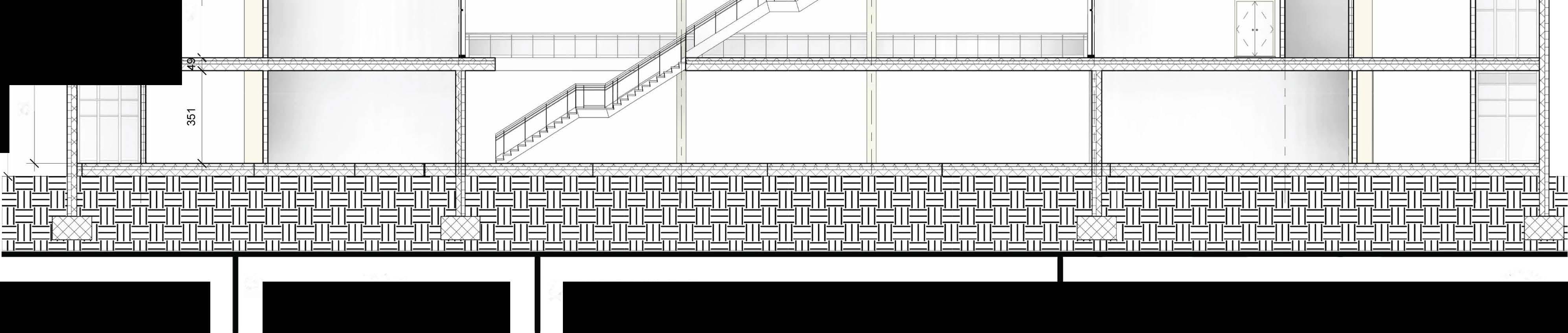
urb/bme I 1 2 240 480 " {-�I 372 § 83 83 74 372 { / § �I � P.11 Arct1itect Ahmad Aldebsi ' 3 720 71 727 1IB1 727 ,f' 5m 20m 10m 4 Faculty ofArchitecture Project BUDAPEST UNIVERSITY OF TECHNOLOGY AND ECONOMICS NEO 5 6 7 8 9 5520 841 718 841 720 240 480 799 369 799 372 !10 11 240 74 83 83 :r:9 74 83 / { SECTION BB 47°29'12.1"N 19°05'13.3"E (!)
Environmentalcasestudy.The warmest month is August with average max annual temperature of 15° with peak reaching 30° . The coolest month is January with average max annual temperature of 60° The driest Month is October and the Wettest Month is June.The most humid month is January and the least humid month is April. 73.0% average humidity January is the most rainy days. October the least rain occur in and average rain days are 127 days July has the maximum hours ofthe sunlight. December is the lowest averagehours of sunlight


Budapest, Budapest, Hungary
47.434N, 19.154E Elevation: 115 m I Climate Class: Cfb I Years: 1990-2019
Data Source: CRUTimeSeries v4.05 https catalogue.ceda.ac.uk uuId c26a65020a5e4b80b20018[148556681


Architect Faculty ofArchitecture Project
urb/bme Ahmad Aldebsi BUDAPEST UNIVERSITY OF TECHNOLOGY AND ECONOMICS NEO
Distribution ofTemperature [°C) 25 I 20 . ! ! 15 ! ! 10 ! 5 0 -5 � + + t r Jan Feb Mar Apr May Jun Jul Auq Sep Oct Nov Dec
<OOC: 300( � 20oC i 100( ooe -lOCCL �� 23da� i lSdays ,..� ''" f<b ■ Maxt� • Mintemp A�raoeminandmaxtemperaturesin&Jdapest,1-U'lgary Copyright<O2023 weather•and-dimate.com1 ■ Rainydays Oda�.LL-i-"'-'-+..__._+-'--'-l..._.-+-L.L.+-"-,&.+-LL+-'--"-1....LI'"+-.__._+-'-__...._ j � M -W � M M --m -� Avttagerainydays(rain/snow)in&Jdapest,1-ulgary �<O2023 wuther-and-dimate.com '2 f I Windspeed � M -W � M M --m -� AYeta9('windspeedinBudapest,tt.ngary (.opyrioht<O2023 weather-and-climate.com Distribution of Precipitation [mm] 140 • 120 • 100 80 60 40 20 0-.....---..--...---,.-......-......-..---,---,----........ 100% 20% 300hB 250hB 50hB J,n Jan Feb Mar Apr May Jun Jul Auq Sep Oct Nov Dec f,b "" ClimateCl1arts.net • tuntdity � M M • • m -� I AYttaoerelati¥ehumidityin8uda�t,1-tJngary Copynoht(02023 weather-and-dimate.com AveragemonthlysunhoursIn&Jdapest,t,t,ngary Copyright:(02023 we.ather-and-dimate.com � M -W � M M --m -� AYUageprecipitation(rain/snow)InBudapest,1-k,ngary Copyright¢l2023 weather-and-dimate.com P.12 1m4m ENVIRONMENTAL ANALYSIS 47° 29'12.1"N 19° 05'13.3"E C!) 2m
Eheating =A(qheating·elMlatingprima+Pheatlng ·ee1ee1r1cprima)[Wh/m2a)
E,,entllatlon =A· Pventilation·ee1ec1rcprimal [Wh/m2a)
Ehotwatcr =A· Pt>otwator • ehotw�tvrprlmal [Wh/m2aJ
Et ghting =A• Plighting·eeiectrcprima (Wh/m2a]
EN!newabte :shou d be estimatedbased ontheareaoftherenewablesystems:

-PVpanelsmayproduceabout360.000Whlm'ae1ectrieenergyinayear. -Soarcollectorsmayproduce590.000Whim'a80ef9>'inayearinHungary.
Theannualprimer,energy(Ep) demand of thebuilding can beforecasted usingthe following equation (please note that the annua lighting energy demand may be neglectedforresidentia buildings):
Ep =(Ehea ng+Ev,ntila�on+ Ehotwatvr+Eiighting-Ervnvwabe)/1000 [kWh/m2a]

urb/bme Architect Faculty of Architecture Project Ahmad Aldebsi BUDAPEST UNIVERSITY OF TECHNOLOGY AND ECONOMICS NEO
of enerqv
area q p e I E heating 121220 1595 55 4 electric peak 2.5 E ventelation 45450 1818 10 electric off peak 1.8 E hot water 2760 115 20 natural gas 1 E light 63750 2125 12 fuel oil I 1 E renewable 142239.8 coal I 0.95 EP 90.9402 district heating 1.2 A/V 0.3125 district heating co-generate 1.12 Er 92.05 wood,biomass 0.6 building perf 98.7943509 Re-energy I 0
Results
calculation
= Eheatina =03'IE3"J8+F3'J3l Eventelation =D4'(F4'J3) Ehotwater =D5'F5'J8 Elight =D6'F6'J3 Erenewable =61%'(C6+C5+C4+C3J ' EP =IC3+C4+C5+C6-C7)I1000 -•AIV =53001(5300'3.2) ' Er =40.8+(164'C9) buildingperf =100'C8/C10 0 RoomSoh•d Ar•am1 l•vel Nam• Level1 chimney ' 9 Level1 \..I.C 9 Leve11 WO ' 10 Level1 E. switch 10 Leve11 electric switch 10 Level1 \..I.C 10 Level1 WO 11 Level1 pantry 15 Level1 CClY 16 Level1 cctv 17 Level1 droppingarea ' 24 Leve11 heating plant 29 Level1 cloakroom ' 30 Level1 cloakroom 31 Level1 storage 32 Level1 heating plant 33 Leve11 managerroom 35 Level1 adminstrative 43 Leve11 gas boiler 47 Level1 adminstrative 56 Level1 gas boiler ' 82 Level1 adminstrative 130 Level1 gallarey ' 323 Leve11 lobbyand corridors 380 Level1 lobbyand corridors areafor panels areafor panels ' ' Buildingtype Heating Ventilation Cooling Hotwater Resident al Offices Educatonal Industrial [Whlm2a] {Wh/m2a) [Wh/m2a] (Whlm2a] q..., """' i)velllilalion ,,._, """'-· 40 3 30 25 40 30 2 45 45 15 55 4 45 10 20 30 2 35 15 20 Floorareaspecificannualheal111genergydemand(q)and annualelectricenergydemandofthe variousbuildingsystems(p). lighting [Whlm2a] �tir,g 8 22 12 10 There are specific regulations for specific building functions and building shel area and buiding volume(AN) ratios describing the maximum allowed building energy consumption, accordingtothetable. ANratio Ep Residential E.,Office Ep Educational kWh/m2a kWh/m2a kWh/m2a ANS:0,3 110 132 90 03sAN�13 74+120· AN 94+128· AN 40 8+164· AN AN:?;13 110 260 254 E,:primalenergycon$umption valuesprovidedbyreg:ulalion$ P.13 5m 20m 10m . I area q p " =+A33+A34+t55 4 electricpeak 2.5 =A26+A25+A 10 electricoff peak 1.8 =A18+A19+A2 20 naturalgas 1 =A18+A19+A2 12 fueloil 1 coal 0.95 districtheating 1.2 district heatina co-aenerate 1.12 wood.biomass Re-enera'J RoomSoh•dul• Numb•r Volum• Ar•a 5 2.89m' 9 12 20.88m' 10 19 20.88m' 14 6 23.95m' 33 22 24.42m' 34 11 24.84m' 34 18 23.74m' 34 15 25.83m' 45 17 36.94m' 50 14 39.34m' 51 26 42.66m' 51 4 58.27m' 84 16 71.23m' 86 7 72.56m' 91 25 76.69m' 92 20 79.16m' RoomSchedule 10 81.28m' Area 23 86.56m' 3 103.67m' 9 9 114.69m' 10 21 136.09m' 14 8 199.94m' 33 24 316.30m' 34 42 787.58m' 34 43 927.73m' 34 45 =C7l360'1.2 50 51 51 84 86 91 92
method of energy calculation PLEASE CHECK THE ATTACHED EXCEL FILE
GROUND FLOOR/ PLAN - 3D SECTION 0.6 0 Lev•I Nam• Numb•r Volum• I I Level2 WO 29 20.88m' Level2 WO 28 24.47m' Level2 pantry 40 34.18m' Level2 classroom 33 80.96m' LeveI2 calssroom 30 82.16m' Level2 classroom 31 82.16m' Level2 classroom 32 83.69m' Level2 adminstrative 39 110.45m' Level2 classroom 34 121.41m' LeveI2 adminstralive 35 125.09m' Level2 storage 41 125.08m' Leve12 classhall 36 205.12m' Level2 seminar 27 210.63m' Level2 workshops 38 222.87m' Level2 workshops 37 223.48m' Lev&I Name Numbiitr Volume leve13 WO 29 20.88m' level3 WO 28 24.47m' level3 pantry 40 34.18m' leve13 classroom 33 8096m'I l&vel3 calssroom 30 82.16m' leve13 classroom 31 82 16m' level3 classroom 32 83.69m' leve13 adminstrative 39 110.45m'I level3 classroom 34 121.41m'I l&ve13 adminstrative 35 125.09m' level3 storage 41 125.08m' level3 classhall 36 205.12m' leve13 seminar 27 210.63m' level3 workshops 38 222 87m' l&ve13 workshops 37 223.48m' Toclassify(A•,A. 8. C.D. E.F.G. H. I) the building energy periormance ofthe bu�ding we must compare (¾) the calculated (Ep) overall building energy performancevaluetothevaluedescribedbytheregulaton(E,). 100·Epe,1_,..,../E,eguiation[%] AccordingtothecalculatedratiO(%]value.thefollowingcanilicatlonclassesmay bedetermined.Forinstance.ifthe calculated%ratoisbetween96-100¾thenthe ·c. According to requiremenr dassifteation rating should be indicated and highlighted 47°29'12.1"N 19°05'13.3"E (!)
Double facade layers.ETFE Fabric Type Ethylene-tetrafluoroethylene, also known as ETFE, offers designers a great solution to alternative options. ETFE facades integrate modern lightness, durability, design, and ecological values.
The main advantages of ETFE fabric facades: Less support material due to being lightweight -Flame retardant -Transparency similar to glass

Self cleaning - High-ranking acoustic properties - Architecturally dynamic for cost effective design in virtually any shape- Long service life - 100% recyclable - Cost less than traditional glass panels.

ETFE foil.is a chemically inert material. It resists all chemica agents combining surface tension and provides great resistance to all environmental pollution. The advantage of self-cleaning properties is that they do not weather or require cleaning other than general rainfall.
The excellent light transmission properties (>92%) and the low weight compared to glass panels (about 1%). allow to create lightweight architecturally dynamic structures and roofing systems. In addition, it is possible to achieve control of both sunlight transmission and effective insulation properties to meet codes when using PTFE in pressurized pillows.


https://facadescreen.corn/index.php/etfe-fabric/
Architect Faculty of Architecture Project urb/bme Ahmad Aldebsi BUDAPEST UNIVERSITY OF TECHNOLOGY AND ECONOMICS NEO
first layer of the double skin facade made of curtain wall allONing to control the amount of air going inside the building
steel grid made out of small horzontal beams fixed in vertica curtain wall mulions, vertical cables to bend the ETFE sheets around it
ETFE sheets reflecting sun rays allowing on� sun light to go through fixed around tensiled steel cables
P.14 5m 20m 10m GROUND FLOOR/ PLAN - 3D SECTION 47°29'12.1"N 19°05'13.3"E C!)
Renewable energy preliminary analysis. Solution 1 -PV panels.

PV panels are easily applicable to use for my building. It is easy to install and has great advantages in producing energy. My building is oriented to south, so access to solation is full. The diadvantage is only that it's pricy in the beginning, and adds weight to overalI structure.
The installation of Photo-Voltaic (PV) panels require the following considerations:
• PV panel size: 90 cm x 160 cm, thickness: 4 -6 cm, weight: 15 - 30 kg, • Generated electric power: 160 - 360 W/panel (0,16 - 0,36 kW/panel), • Preferred orientation is south (south-east, southwest), close to horizontal
And vertical installation positions may also be used, • If electric utility grid is not available close to the building site, the PV panel installation requires a battery cabinet for energy storage, • If electric utility grid is available on site the PV panel installation requires a converter from 12V or 24V Direct Current (DC) to 230V or 110V Alternating Current (AC), and a separate energy meter.

urb/bme P.15 Architect Faculty of Architecture Project
ECONOMICS NEO
Ahmad Aldebsi BUDAPEST UNIVERSITY OF TECHNOLOGY AND
5m 20m GROUND FLOOR/ PLAN - 3D SECTION 47°29'12.1"N 19°05'13.3"E C!) 10m
Renewable energy preliminary analysis. Solution 1 - Doubleskin facade.Energy efficiency-Improved thermal comfort -Noise reduction-Design flexibility-Increased sustainability
How it works:

Thermal insulation: The inner layer of the double skin facade is typically made of materials with high thermal insulation properties, such as insulated glass units or thermally efficient panels. This layer helps minimize heat transfer between the exterior and interior of the building.
Ventilation: The air cavity between the layers facilitates natural ventilation. Openings or vents at the top and bottom of the facade allow fresh air to enter the cavity, and warm air to escape, creating a stack effect. This promotes air circulation and heat dissipation.
Solar shading: The outer layer of the double skin facade can incorporate shading devices such as louvers, fins, or brise-soleil. These elements help block direct sunlight, reducing solar heat gain and preventing overheating.
Night cooling: During cooler nighttime temperatures, the double skin facade can be used for night flushing. By opening the vents in the cavity, cool air can be drawn in, absorbing the building's excess heat and providing thermal comfort for the following day.
Control systems: To optimize performance, automated control systems can be integrated into the passive cooling system. These systems monitor external weather conditions, internal temperatures, and occupancy levels to adjust the ventilation and shading accordingly.

b/b Architect Ur me Ahmad Aldebsi Faculty of Architecture Project BUDAPEST UNIVERSITY OF TECHNOLOGY AND ECONOMICS NEO
P.16 20m GROUND FLOOR/ PLAN - 3D SECTION 10m 47°29'12.1"N 19°05'13.3"E C!)
The Components of Concrete Framed Structures
1. Foundation
Themainfunction ofthefoundation istosupport thestructureand transfertheload carried bythecolumnsandbeamsaboveit tothesolidbase.
Thefoundation formsaflatand solid surfaceforthe structure. On which the structure ofthebuildingiserected.
2. Column
Columns are used tosupportbeamsorarchesin aframe structure. Theload onthe columncomesfrom the upper part ofthe walls orceiling.
Thecolumn canbedesigned toresistexternalforces as pertherequirementlikewind or seismicengineering.
3. Shear wall

Instructuralengineering, the shearwallisdesignedtowithstandanearthquakeforce, which acts asaverticalmember. Shear wall isused as a structuralelementin high risebuildings. Shearwalls areknown aslongcolumnsin tallbuildings.The shear wall lookslike a wall.Theyresist externalloadssuchaswind and earthquakeloads.
4. Beam
Beams arevarious horizontal load-bearing members in aframed structure. Thefunction of thebeamcarries theload of the slab andthe direct load of the masonry walls and their self-weight

In a concreteframe, some beams aresupported on otherbeams.The beam can be supported on thecolumn toforman integral part of theframe.The beamhas mainlyflexural membersin theconcreteframe.Theyare divided intotwotypes accordingtothe function.
5. Slab
Concrete slabs area commonstructuralelement ofmodem buildings. Theslab is aflat, horizontalsurfacemade of castconcrete. Is. Steel-reinforced slabs usuallyhave a thicknessof100 to150 mm. Mostlyslab is used to buildfloorsand ceilings. In some domesticand industrialbuildings, thickconcrete slabs areused to makethebasefloorsurface.
Cast-in-situ slabsare used in avarietyofhigh-risebuildingsand large shopping centersaswell as homes.
urb/bme
Ahmad Aldebsi BUDAPEST UNIVERSITY OF TECHNOLOGY AND ECONOMICS NEO
P.17 1m 4m 2m STRUCTURAL DIAGRAMS 47°29'12.1"N 19°05'13.3"E (!)
urb/bme Ahmad Aldebsi BUDAPEST UNIVERSITY OF TECHNOLOGY AND ECONOMICS NEO
Requirementsforthemainstructuralgroups:
ForExteriorFacade:
Sinceourexteriorfacadeithassheardteracewith corridoronalloverofit(notheatedterace), weneedtofixthermalbridgeinthe connectionbetweenslaband canteliverusingSchockElement
ForinteriorFacade: � EPSThermalinsulation �). layerwith 15cmthicknes.
staircase:
25mmacousticlayer.
Structuralloading
-Thebuildingmustbearhorizontaland verticalloads.Adesignliveloadwascalculated forthepotentialsnowloadontheuppermostslab. Also, astheroofisaccessible, liveloadisalsotaken .,,,., intoconsideration-Fortheintermediateslabs, ,,,-:::;· liveloadsarealsoconsidered.
-Shearwallsaredesignedtobearthewindloads.Skeletonframestructure ./� �/ s�
twowayslab,25cmmon.RC25/30Slabisused.BEAMS ,,,,,,,, 40x50cmRectangularRCBeamsareused. / /4 RCshearwallscarryearthquakeloadsdowntothefoundation.,,,,/" Theyprovidelargestrengthandstiffnesstobuildings ,.,../ inthedirectionoftheirorientation. _,,.,-:,;

COLUMNS
30x30cmRectangularRCColumns.
Load transfering model in 3D.Slabs of all floorsare one-way slabs and two- way slabs. They consistof R.C flatslab, which issupported bygirders. The slab

takesthe vertical loadsand transfer them to the beams ehich are situated in cross-direction of the building.
therefore the columns transfares the loads into the soil throught the foundation
.··
�✓
/�
P.18 1m 4m 2m STRUCTURAL DIAGRAMS
47°29'12.1"N19°05'13.3"E (!)
The most important points we need to make (how the project can succeed).
The main participants and their tasks are:
a- Client:

Clients either identify user potential or create the need for the facilities and raise the necessary financial resources for their creation. They initiate the construction process by commissioning various construction professionals to build to specific requirements.
During the design and construction phases, the client directly or indirectly monitors progress, time, cost, and quality objectives and sanctions any necessary major variations to the design. Finally, on completion, it is the client who either disposes of the product at the marketplace or takes occupation and bears the repairs and maintenance cost of his/her investment. In my project's case, the client is a private investor.
b- Project manager/Quality Surveyor
Quality surveying is performed by a firm hired by the client. They follow up on the prOJect in both phases of planning and construction. They are responsible for controlling the plans and the construction work, they also are expected to propose alternatives to the plan for the client in case of technical or construction difficulties.
Among their tasks:
- Control the plans according to the standards and the legal prescription.
- Control the assignment of the building
- Control the construction process to ensure the quality of hidden structures and used materials.
Arct1itect Faculty ofArchitecture Project urb/bme Ahmad Aldebsi BUDAPEST UNIVERSITY OF TECHNOLOGY AND ECONOMICS NEO MINDMAP
Identify Stakeholders .mage Stakeholders Engagement Plan Stakeholder Management Control Stakeholder Management Plan Procurement Management Conduct Procurements Control Procurements Close Procurements Plan Risk Management Identify Risks Perform Qualitative Risk Analysis Perform Quantitative Risk Analysis Plan Risk Responses Control Risks Plan Communications Management Manage Communications Control Communications Plan Human Resource Management Acquire Project Team Develop Project Team Manage Project Team Plan Quality Management Perform Quality Assurance Control Quality Stakeholder Procurement [ Risk Communication Human Resources [Quality
Project Management the most important points we need to make. how the project con succeed
P.19 1m 4m 2m REQUIREMENTS lntergration Scope Time] Cost] Develop Project Charter Develop Project Management Plan Direct and Manage Project Work Monitor and Control Project Work Perform Integrated Change Control Close Project or Phase Plan Scope Management Collect Requirements Define Scope Create WBS Validate Scope Control Scope Plan Schedule Management Define Activities Sequence Activity Estimate Activity Durations Develop Schedule Control Schedule Plan Cost Management Estimate Costs DetermineBudget Control Costs -------
47°29'12.1"N 19°05'13.3"E (!)
c- Investor:
- Ensure the financial resources
- Make the final decisions regarding accepting decisions
d- Authorities:
- Ensure the legal environment
- Tasks and duties
- Provide building permit
- Provide permission to use
- Give consent for the plans
e- Architect
Traditionally, the design function in the construction process is the responsibility of an architect who is a professionally qualified person whose role is to interpret the client's proJect requirements into a specific design or scheme. Design is taken to include appearance composition, proportion, structure, function, and economy of product, but in addition, the architect performs the function of obtaining planning permission for the scheme. Many times the architect supervises and organizes the entire construction process, starting with consulting with the client and ending with commissioning.
As an established practice, the architect plays the leading role in the construction process. He or she collects, coordinates, controls, and disseminates project information to all project participants.
f- Contractors
- Prepare and organize the construction process according to the contract
- Take part in the tendering process
- Communication between clients and sub contractors
- Excute the building construction according to standards
- Cooperate and communicate with the designer team.
g- Structural Engineer

The structural engineer acts as an advisor to the architect on all structural problems such as stability of the structure, suitability of materials proposed, structural feasibility of the proposed design, and sizes of structural members for a construction project. Normally, the structural design engineer submits his/her various structural calculations to the area local authority for approval at the same time as the architect submits his/her drawings for building regulations approval. In addition, the structural engineer performs structural design and supervises his or her specialist area of the construction project during production on site.
h- Services Engineer
Like the structural engineer, the services engineers (plumbing, electrical, heating and ventilating, air conditioning, sanitation, lifts and escalators, etc) contribute to the building design process to ensure that thermal and visual comfort are achieved effectively. For this reason, they analyze the client's requirements and priorities and advise the architect on the most appropriate design solution.

i- Users
The final user of the project will be the inhabitants of the project for this residential co-housing project. and the shop owners of the commercial level. In additioin users of the parking from the neighborhood
urb/bme Arct1itect Faculty ofArchitecture Project Ahmad Aldebsi BUDAPEST UNIVERSITY OF TECHNOLOGY AND ECONOMICS NEO
P.20 1m....,____ 4m 2m
8/ \� \ REQUIREMENTS
47°29'12.1"N 19°05'13.3"E (!)
Participants and their tasks diagram
urb/bme
Arct1itect Faculty ofArchitecture Project Ahmad Aldebsi BUDAPEST UNIVERSITY OF TECHNOLOGY AND ECONOMICS NEO
Name
Settingupthesite
Stippingtopsoil,cleaningvegetation
Conslructionofrnncretepilefoumfation
hrs!slepof.Excavationfordeaningthesite
ConslrnctionoftheConcretepiles
secondstepofexcavationforsitecleaning
Gravelbackfill&reinforcedscreed
Pvcwatetproofinglaying
Constructionofthefoundationslab
Constructing skeletoncolumnsandwall(Basementfloor)
Striking formworkofcolumns andwall(13ascmcnl lloor)
PrepmingRe slab (Fromwork, reinforecement, concrete)
Striking slabfonn,vork( Horizontal elements)
PreparingRe staircase(nascmcntfloor)
Striking stairformwork(11ascmcnt floor)
Constructionofwallsandcolumnsreinforcement(Groundfloor)
Conslrnctionofwc1llsandcolumnsformwork(GroundOoor)
Concreteworksforwallsam! colums(Groundiloor)
Remov:iloffonn\vorksofthewalls&columns(GrotmdOoor)
frameworkofthestairs(Groundfloor)
Reinforcementofthestrairs(Groundfloor)
Concreteworksofstairs(Groundfloor)
lnsh1llationoftheformworkfortheslab(FirslOoor)

Reinforcementoftheslab(.FirstOoor)
Concreteworksoftheslab(Firstfloor)
Constructionofwalls&columnsreinforcements(Firstfloor)
Constmctionofwalls&columnsformwork(Firstfloor)
Concreteworksforlhcwalls&columns(Firstlloor)
Removalofformworkoflhewall(hrstlloor)
frameworkofthestc1irs(hrstlloor)
Reinforcementofthestairs(Firstfloor)
Concreteworksforthestair(Firstfloor)
Tnstallationoftheformworkfortheslab(Secondfloor)
Reinforcementoftheslab(Secondlloor)
Concreteworksforlhcslab(Secondfloor)
Const:rnctionofwalls&cohum1sreinforcement(Secondfloor)
Const:rnctionofwalls&colmm1sformwork(Secondfloor)
Concreteworksforthe,valls&columns(Secondfloor)
Concreteworksforthewalls&columns(Secondfloor)
Fonnworkofthestairs(Secondfloor)
Reinforcementofthestairs(Secondfloor)
Concreteworksfortheslilirs(Secondfloor)
lnstallationoftheformworkfortheslab(lbirdlloor)
Reinforcementoftheslab('lbirdlloor)
Name
Concreteworksfor theslab(Thirdfloor)
Construclionofwalls& columnsreinrorcement (Thirdnoor)
ConstrucLionofwalls& columnsfonnwork (Thirdnoor)
Concreteworksforthe,valls& columns(Thirdfloor)
RemovalorfonnworksofLhc walls& columns(Thirdnoor)
Fonnworkofthestairs(Thirdfloor)
Reinforcement ofthestairs(Thirdfloor)
Concrete worksforthestair(Thirdfloor)
lnsLallationofthefonnwork for theslab(Rool)
Reinforcmentoftheslab(Rool)
Rcinstallationoftheform,vorkofslab(Roof)
Installationorfacadeclements(Firstnoor-Fourthnoor)
Roofinsulationworks
Rooffinishingworks
Tnteriorfinishingofthewallsforallfloors
Interiorfinishingorthewallsforallnoors
Installationofpartitionwallsforallnoors
Interiorfinishingoftheflooringforallfloors
Ventilationequipment
Electricalequipment
Furnishingthe bathroomsandKitchens
FurnishingthePublicareasonthegroundnoor
Furnishingtheclassrooms
Placementofplantsonterraces
Ratinginstallation(Firstfloor- third floor)
Correcting faults
Cleaning
Handover
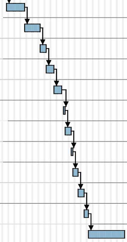
Timetable Tasks Outlinenumber 9 10 11 12 13 14 15 16 17 18 19 20 21 22 23 24 25 26 27 28 29 30 31 32 :B 34 35 36 37 38 39 40 41 42 43 44 Timetable Tasks Outlinenumber 45 4(, 47 48 49 50 51 52 51 54 55 5(, 57 58 59 (JO (,I 62 63 64 65 66 (,7 (,8 69 70 71 72 P.21
1m 4m ....,_,.__..... 2m TIMETABLE Duration 10 10 Duration 10 15 15 12 30 Begindate 12/1/23 12/7/23 12/12/23 12115/23 12/29/23 1/3/24 1/17/24 1123/24 l/'.W/24 2/9/24 2/20/24 2/21/24 2/29/24 3/1/24 3/5/24 1/6/24 3/14/24 3/22/24 3/27/24 4/1/24 4/3/24 4/8/24 4/l0/24 4/15/24 4117/24 4119/24 4/29/24 5/7/24 5/l0/24 5/16/24 5/20/24 5/23/24 5/28/24 5/31/24 6/4/24 6/6124 6/14/24 6/24/24 6/27/24 7/2/24 7/4/24 7/9/24 7/12/24 7/17/24 Begindate 7/19/24 7/21/24 7/11/24 8/8/24 8/11/24 8/16/24 8/20/24 8/22/24 8/27/24 8/28/24 9/2/24 9/9/24 9/20/24 9/26/24 10/4/24 10/18/24 11/8/24 11129/24 12/17/24 12/24/24 112125 1/13/25 1/15/25 1/22/25 1/24/25 1/10/25 2/6125 2/11/25 Enddate I2/6/23 12/11/23 12114/23 12/28/23 l/2/24 1/16/24 1/22/24 l/29/24 2/8/24 2/19124 2/20/24 2/28/24 2/29/24 3/4/24 3/5/24 3/13/24 3/21/24 3/26/24 3/29/24 4/2/24 4/5/24 419124 4/12124 4/16/24 4/18124 4/26/24 5/6/24 5/9/24 5/15124 5/17/24 5/22/24 5/27/24 5/30/24 6/3/24 6/5/24 6/13/24 6/21/24 6/26/24 7/1/24 7/3/24 7/8/24 7/11/24 7/16/24 7/18/24 Enddate 7/22/24 7/10/24 8/7/24 8/12/24 8/15/24 8119124 8/21124 8/26/24 8/27/24 8/10/24 9/6/24 9/19/24 9125124 10/3124 10/17/24 11/7/24 I1/28/24 12/16/24 12/23/24 111/25 1110125 1/14/25 1/21/25 1/21/25 1/29/25 2/5/25 2110125 3/24/25 47°29'12.1"N 19°05'13.3"E Jun9,2023 (!)


urb/bme Arct1itect Ahmad
Faculty ofArchitecture BUDAPEST
AND ECONOMICS Project NEO P.22 s..ning urth..�;,,. 4.0,fay 1-orst step ot lcxc_,v.,\ion tor cle.,rnnv the site 10.0d;ay secondstep ofcxcavat;onforsnccleaning 10.0 day ,1.0,foy Pvc.w.atorproot,nglaymg O.Oday Preparing rlcslab (Fromwork, reinforec.,ment. =,nc,.,,e) C.Oday Shikingslnbfotmwork ( Hor;7ontcil cl.-.mnnt") 1-'rAp.aring He:"'"'"'"""(H"""m,mttlom) :>Oday Ele!-Jill <.lat" 2024 2025 M,u Apr ).foy J,m Jul Allis Stop Ocl Nov Oto<: Mar Ap, - -.,-0<ing.,,.;c,o,mwo_,,(B•••m•m.,00,) , ,d.,� 6.0day Corocwl"work,.lur w..11,. ,rnd colum�(GruurKllluor) frameworkof thestairs (Ground floor) L.Oday Concreteworksof stairs (Groundfloor) 2.0day ln,.tallc,1ionnf thefmmwc,,kfo, theeilnb (Firn1floor) :i.o,foy a I 2.0day Cl.Oday Di Concmtoworksfor thowalls&=lumns (Firstfloor) Rcr,,ow,1offom,-orkof thewc,11 {li,,;tfloo.-) 4.0dc,y Reirof<m,.,menlul lhe�lair,; (riu;lflour) 3.0dny Reirifur"""'""l ofthe�l«l,(SecumJfloor) 6.0day Con!ltructionofw,oll" I!.column"formwork (S,.condfloor) 6.0d,oy Di Corouul-.,wurk" furUu.;w«II"&,;ulumm; (S0<;ondlloor) 2.0dny Concrete worksfor the staim (Second floor) 3.0day ln"tall,itionof the,formwc:,rkIm the,Rlnh (Thirdfloor) !l.Od,iy Rcintorcomcnt otthoslab (Thord tloor) j Cur,oet.,workslo,th.,,;lal, (Thirdflour) 2.0day Coronel.,wurks fur thew,<11�&u,lumm; (Tf,irdflour) Forrnworkof the ..tairn (Thirdfloor) 2.0day neinforcementofthest,.ir" (Thirdfloor) 2.0d,iy Ccncrcte worksfor the stoir (Thirdfloor) c:l.Odoy ln"t,oll,otionofth,.formwr,rkk,r th,."l"h (Roof) 1.0,fay Ruorolur<.0munloliloo"l«l, (Roul) a 9.0day Di Rooffinishingworks 6.0d.iy Interiorfini,.hing of thew;ilksfor;illfloor" 10.0 ,fay b, lnteroorf,rn,.h,ngof theflooringtor ..11floors 12.0day Eloctricaloqu,pmcnt Furn,,.hingthe bathroom,.and Kitchen,. 7.0day Ft1rnishingthe Puhlic"'"''"'onthe, grounrl floor ,>_Oday Furnishingthocl,assrooms 2.0day Correc..-ti,� fault,; JO.Oday 1m....,_,.__..... 4m TIMETABLE 47°29'12.1"N 19°05'13.3"E 2m (!)
Aldebsi
UNIVERSITY OF TECHNOLOGY


urb/bme \ 7 P.23 \ Arct1itect Ahmad Aldebsi 1m 4m 2m Faculty ofArchitecture Project BUDAPEST UNIVERSITY OF TECHNOLOGY AND ECONOMICS NEO [ 0 D ll9§.!li! Gas � Water Wastewater Electricity Fence Transportationroute Gate Gaurd Firstaid Electricalbox Restroom Crane ■ Storage - SocialBlock Office block ■ Wastestorage - Changingcontainer ( CONSTRUCTION PLAN 47°29'12.1"N 19°05'13.3"E (!)
1


b/b Arct1itect Ur me Ahmad Aldebsi R1. 2 mmp.v.c
cm concrete 1mm.I foil
cm mineral.woolaguestic
cm EPS
7
15
2.5
mm waterproofing mm bitominussheet
earth soil A B 720 240 ,, R6 ,--------8 681 182 ijlti iii 2 ,1r 681 � 8 :l] 447 215 � �J :ii .,, C 1 P. 24 5m 20m 10m Faculty ofArchitecture Project BUDAPEST UNIVERSITY OF TECHNOLOGY AND ECONOMICS NEO 960 960 R2.horizental section in foundation 2 mm p.v.c 20cm R.C wall 15cm EPS 10cm R.C wall 3cm air gap neigbourwall ETFEmembrane� -hoolowsectionbeam---_,__ connectedtoRCslab twosteelUsections w,;de(Itogelher c--•r--1 .·_-:L�·::JL COYersheetsurface--� waterproofi�i.....,L----.·', R3. 2 mmp.v.c 7 cm concrete 1mm.I foil 15cm mineral.woolaguestic 2.5 cm EPS 1 mm water proofing mm bitominus sheet 25cm R.C slab 40cmmechanicalgap 5mm false ciliengpanels R3 /-LshapeprofiletocloseP.V. / sheetwi'lhmulion /��ularsteelprofile /1/ toputthefoillayerbhind comingfromverticalrilulion \ �, dripcapflashingproLin9---------- \■l:lki-� curtainwallfroml,,.1er \ \,11211�-Vl( D E F G 5040 240 960 240 1 1 1 SECTION 01 720 / / / / H 1 R4 960 458 458 R3 47°29'12.1"N 19°05'13.3"E (!)
25cmr.cslab
4mmbitumenmembrane waterproofing 4mm,


1layercoldbitumenpatching compound
25cmR.Cslab
40cmmechanicalgap 5mm false ciliengpanels


" Arct1itect Faculty ofArchitecture Project urb/bme Ahmad Aldebsi BUDAPEST UNIVERSITY OF TECHNOLOGY AND ECONOMICS NEO R4 ,_,.... R4. loadbearing wall: 20cm RCwall 15cmmineralwool aquesticinsulation 2mmplaster finishinglayer ___,__ loflXthermallnsulatlon ----blturnRISsealant -- thermallnSWltlon ---- wilhsyrrlhetk:ooncrete externalprotectinglayer, /�drinagelayer ,,/ R6 RS z-_._,,_�i:=:--� --.........-.�....................... D.....:lthe............theR4 RS. 4cmgranitestone finishing / /4cmstonechippingand drainagelayer 2mmsyntheticfilterlayer / / / / / _�1////:// 15cmEPSwaterinsulation •iJL--4 / / / / ///:// / / / 1layersfibrereinforced I 1 2 240 480 {-�I 372 § 838374 372 { / § �I � P.25 ' 3 R6,,o 71 727 1IB1 727 ,f' 5m 20m 10m 4 SBS 25cmR.Cslab 2mmplasterfinishinglayer 5 6 5520 841 718 841 799 799 SECTION 02 7 _4QflOD_1oo,tlSOINa___ 11111\.'p,alll(ttlld..th'ne) �ftmlllll-.M R3
50cmvegetation
storagelayer
R6.
6cmdrainageandwater
10cmEPS
glassfibrereinforced
SBS
8 9 !10 11 720 240 480 240 369 748383 :r:9 372 7483 / { 47°29'12.1"N 19°05'13.3"E (!)
Layer arrangement through building

Bathroom slab
1cmceramictile
1cmAdhesive
waterproofing Lyr
4cmScreed
5cmSubconcretereinforced
Technologicalfoil
3cm Mineralwoolfloating Lyr
5cmEPS foam Lyrforinstallation
25 RCSlab
0.5cm Plaster
Walkable roof
50 cm vegetation
6cm drainage and water
storage layer
10 cmEPS
4 mm bitumenmembrane
waterproofing
4 mm, glass fibrereinforced
SBS
1 layer cold bitumen patching
compound
25cm R.C slab
40cm mechanicalgap
5mm false cilieng panels
Terrace slab
4cm granite stone finishing
4 cm stonechipping and drainagelayer
2mm synthetic filter layer
15cmEPS water insulation
1 layers fibre reinforced
SBS
25cm R.C slab
2mm plaster finishing layer
loadbearing wall
20cm RCwall
15cmmineralwool
aquestic insulation
2mmplaster
finishinglayer
lntermideate slab
2 mm p.v.c
7 cm concrete
1mm.I foil
15cm mineral.woolaquestic
2.5cmEPS
1 mm water proofing
1 mm bitominussheet
25cm R.C slab
40cmmechanical gap horizontal section in foundation
2 mmp.v.c
20cm R.Cwall
15cmEPS
10cm R.Cwall
3cm air gap
neigbour wall
Ground floor
2 mm p.v.c
7 cm concrete
1mm.I foil
15cm mineral.woolaquestic
2.5 cmEPS
1 mm water proofing
1 mm bitominussheet
25cm r.c slab
Courtyard slab
50cmVegetationandplanting
1 lyr thermalinsulationdrainboard
15cm polystyrene foam thermal insulation
1+1lyr 4mmpolyester fiber reinforced SBS
1 lyr Cold bitumen
10-cm Concrete inclination layer
25cm RC slab construction
Stair Flight
3cm Limestone Covering
1,5cm Mortar bed
20cm RC stair flight
Landing slab
3cm Limestone Covering
1,5cm Mortar bed
6,5cm Concrete screed
1 lyr PE Foil
2,5cm Mineral wool (floating layer)
25cm RC slab construction
b b Arct1itect Ur / me Ahmad Aldebsi Faculty ofArchitecture Project BUDAPEST UNIVERSITY OF TECHNOLOGY AND ECONOMICS NEO
P.26 5m 20rn 10rn
LAYER ARRANGEMENT
47°29'12.1"N 19°05'13.3"E (!)

