
GC040VX, GLC040VX, GC050VX, GLC050VX, GC055SVX,
GLC055SVX, GC060VX, GLC060VX, GC/GLC070VX (C910) SERVICE MANUAL CONTENTS
General
WARNING
The lift truck must be put on blocks for some types of maintenance and repairs. The removal of the following assemblies will cause large changes in the center of gravity: mast, drive axle, engine and transmission, and counterweight. When the lift truck is put on blocks, put additional blocks in the following positions to maintain stability:
• Before removing the mast and drive axle, put blocks under the counterweight so the lift truck cannot fall backward.
• Before removing the counterweight, put blocks under the mast assembly so the lift truck cannot fall forward.
The surface must be solid, even, and level when the lift truck is put on blocks. Make sure that any blocks used to support the lift truck are solid, one-piece units. See the Operating Manual or Periodic Maintenance 8000YRM1762.
NOTE: For exhaust system procedures on lift trucks equipped with a PSI 2.4L engine go to Fuel System PSI 2.4L 0900YRM1757.
NOTE: For exhaust system procedures on lift trucks equipped with Kubota engine go to .
NOTE: For exhaust system procedures on lift trucks equipped with Yanmar engine go toExhaust System Repair in this manual.
This section contains the description of the frame and connected parts; procedures for removing and installing counterweight, hood, overhead guard, engine, transmission, cooling system, and exhaust system (see above NOTES). Checks for the operator restraint system and procedures for the repair of tanks and installation of safety labels are also included.
Description
The frame is one weldment and includes the hydraulic tank and fuel tank for gasoline or diesel fuel. See Figure 1.
There is a counterweight for each capacity of lift truck. The counterweights are similar in appearance, but are different weights.
See Table 3 for lift truck models:
• GLC20-35VX (GC/GLC40-70VX, GC/ GLC055SVX) (C910)
See Table 4 for lift truck models:
• GLP/GDP20-35VX (GP/GLP/GDP040-070VX) (D875)
The muffler is fastened to the frame inside the counterweight.
The overhead guard, cowl, and hood are installed on the frame. The hood is connected to the frame with hinges. Two gas-controlled springs provide assistance when raising the hood and hold the hood in the open position. The floor plate and side covers can be removed for access to the engine, transmission, and other components.
1.COWL PLATE
2.FENDERS
3.FRAME
4.HOOD MOUNTS
REMOVE
5.COUNTERWEIGHT MOUNTS
6.FUEL TANK (GAS OR DIESEL)
7.HYDRAULIC TANK
Hood, Seat, and Side Covers Replacement
1. Slide seat to the closest position to steering column.
2. Fully tilt steering column forward.
3. If your truck is equipped with an LPG tank, swing tank off to the side.
4. Raise latch on the left, front corner of the hood to unlatch and lift up hood. See Figure 2.

5. Remove floor mat and floor plate.
See Figure 3 for lift truck models:
• GLC20-35VX (GC/GLC40-70VX, GC/ GLC055SVX) (C910)
SeeFigure 4 for lift truck models:
• GLP/GDP20-35VX (GP/GLP/ GDP040-070VX) (D875)
6. Remove two capscrews holding left and right rear side covers to the frame. Remove rear side covers from frame.
See Figure 3 for lift truck models:
• GLC20-35VX (GC/GLC40-70VX, GC/ GLC055SVX) (C910)
See Figure 4 for lift truck models:
• GLP/GDP20-35VX (GP/GLP/ GDP040-070VX) (D875)
Figure 1. FrameNOTE: SWIVEL SEAT AND VENTED HOOD ARE OPTIONAL FEATURES.
A. SIDE VIEW OF HOOD AND SEAT
B. SIDE VIEW OF HOOD
1.SEAT
2.HOOD
3.FRAME
4.SEAT WIRE HARNESS
5.SEAT WIRE HARNESS CONNECTOR (WITHOUT ELECTRONIC CONTROL)
6.SEAT WIRE HARNESS CONNECTOR (WITH ELECTRONIC CONTROL)
7.CABLE CLIPS
8.HINGE SCREWS
9.GAS SPRING
C. BOTTOM VIEW OF HOOD
D. SIDE VIEW OF VENTED HOOD WITH SWIVEL SEAT
10.ATTACHMENT HOLES ATTACHING HOOD TO SEAT (SEMI-SUSPENSION)

11.SEAT WIRE HARNESS BRACKETS
12.SEAT LINER
13.HOOD LATCH
14.ATTACHMENT HOLES ATTACHING HOOD TO SEAT (NON-SUSPENSION)
15.ATTACHMENT HOLES ATTACHING HOOD TO SEAT (FULL SUSPENSION)
16.SPACER
1.LOWER STEERING COLUMN COVER
2.UPPER STEERING COLUMN COVER
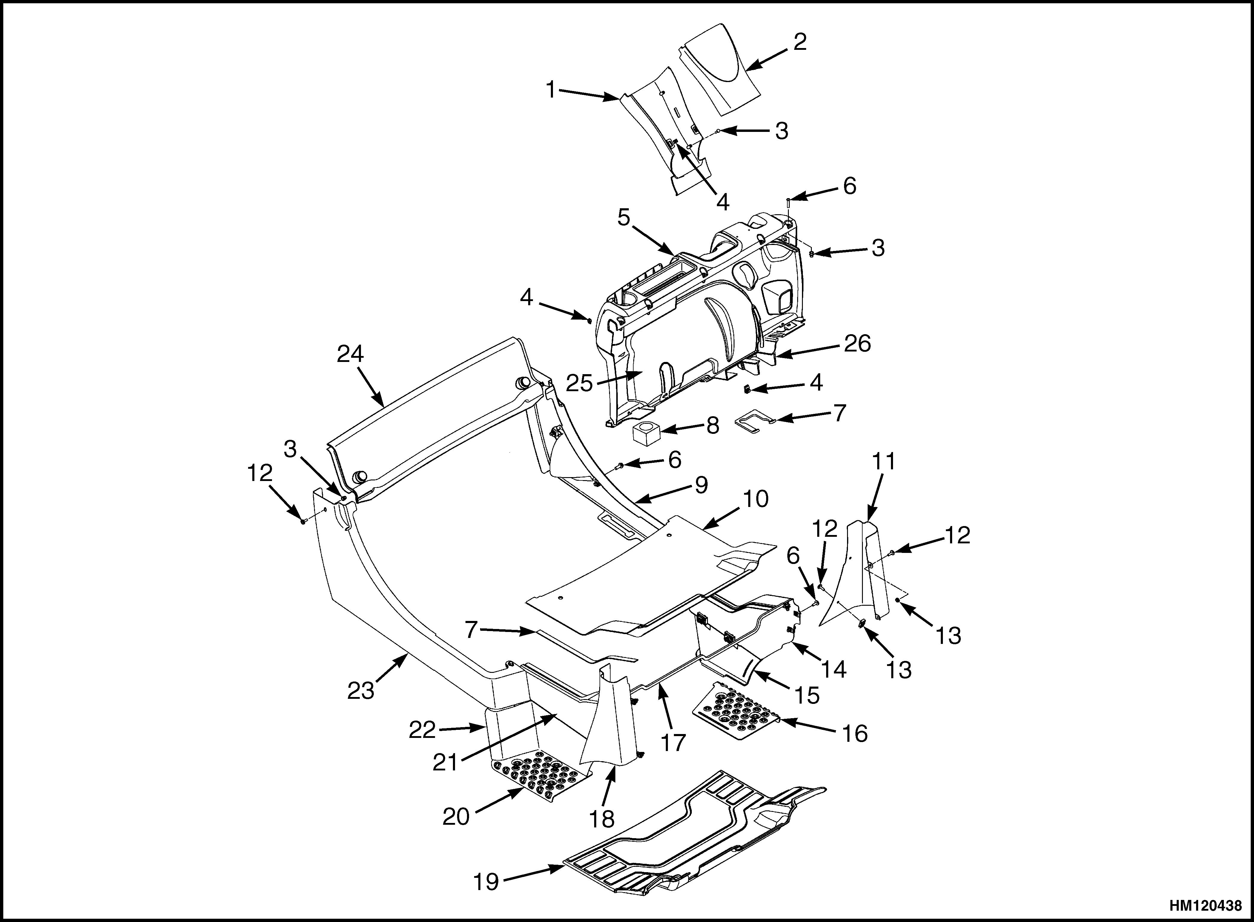
3.INSERT 4.CLIP
5.DASHBOARD
6.CAPSCREW
7.SEAL 8.GROMMET
9.LEFT HAND REAR PANEL
10.FLOOR PLATE
11.LEFT HAND FENDER COVER 12.SCREW 13.NUT
14.LEFT HAND FRONT PANEL
15.LEFT HAND STEP PANEL
16.LEFT HAND TREAD PLATE
17.PLATE ASSEMBLY SEAL
18.RIGHT HAND FENDER COVER
19.FLOOR MAT
20.RIGHT HAND TREAD PLATE
21.RIGHT HAND FRONT PANEL
22.RIGHT HAND STEP PANEL
23.RIGHT HAND REAR PANEL
24.RADIATOR COVER
25.KICK PANEL
26.PLATE ASSEMBLY
Figure 3. Side Cover, Floor Plate, and Cowl Components GLC20-35VX (GC/GLC40-70VX, GC/ GLC055SVX) (C910)
1.DASH ASSEMBLY
Legend for Figure 4
7. Remove two capscrews holding left and right fender covers to front overhead guard leg. Remove covers.
See Figure 3 for lift truck models:
• GLC20-35VX (GC/GLC40-70VX, GC/ GLC055SVX) (C910)
See Figure 4 for lift truck models
• GLP/GDP20-35VX (GP/GLP/ GDP040-070VX) (D875)
8. Remove four capscrews holding left and right front side covers to frame. Remove covers.
9. Fully lower steering column.
10. Remove upper steering column cover by pulling up on upper steering column cover to release latches (one on either side), and pulling cover away from steering column. See Figure 5.
11. Remove five allen screws (see Figure 5) from dash and cowl. Remove four clips, located underneath dash, that attach dash to the kick panel. Lift to remove dash.
12. Lift the kick panel to remove from truck.
See Figure 3 for lift truck models:
• GLC20-35VX (GC/GLC40-70VX, GC/ GLC055SVX) (C910)
See Figure 4 for lift truck models:
• GLP/GDP20-35VX (GP/GLP/ GDP040-070VX) (D875)
25.CAPSCREW
27.INSERT
13. Remove three capscrews holding the seal plate. Remove seal plate. See Figure 6.
14. Disconnect seat wire harness connector. See Figure 2.
CAUTION
When removing the seat from the hood, DO NOT use an impact wrench to remove the capscrews. Damage can be caused to the threads on the screws and in the holes.
15. If seat is to be removed, and truck is equipped with a non-swivel seat, remove seat wire harness from seat wire harness brackets that are attached to the underside of hood. Remove the cable clips from the seat wire harness. If truck is equipped with a swivel seat, remove seat wire harness from seat wire harness bracket attached to underside of the hood and behind the seat (see Figure 2).
16. Remove four capscrews and washers holding the seat to hood. Lift seat off the hood. Pull seat wire harness through hood. See Figure 2.
17. Remove capscrews and washers at the top of gas springs. Remove gas springs from hood.
18. Remove hinge screws, located in the rear of the hood.
19. Lift hood from the truck. See Figure 2.
NOTE: TOP VIEW OF DASH SHOWN.
A. INDICATES TO PULL UP TO UNLATCH
1.ALLEN SCREWS
2.COWL
3.UPPER STEERING COLUMN COVER
 4.LOWER STEERING COLUMN COVER
 1.CAPSCREWS
2.SEAL PLATE
1.CAPSCREWS
2.SEAL PLATE
INSTALL
1. Place hood onto the lift truck frame.
2. Install hinge screws, located in the rear of the hood, and tighten to 38 N•m (28 lbf ft). See Figure 2.

3. Align top holes in the gas springs with holes in hood. Install capscrews and washers to attach gas springs to hood. Tighten capscrews to 19.2 N•m (170 lbf in).
See Figure 7 and Table 1 for lift truck models:
• GLC20-35VX (GC/GLC40-70VX, GC/ GLC055SVX) (C910)
See Figure 8 and Table 2 for lift truck models
• GLP/GDP20-35VX (GP/GLP/ GDP040-070VX) (D875)
NOTE: LEFT SIDE SHOWN
A. MOUNTING LOCATION FOR CYLINDER END OF GAS SPRING FOR NON-SUSPENSION SEAT
B. MOUNTING LOCATION FOR CYLINDER END OF GAS SPRING FOR SEMI OR FULL SUSPENSION SEAT
C. MOUNTING LOCATION FOR CYLINDER END OF GAS SPRING FOR SEMI OR FULL SUSPENSION SEAT WITH CAB
1.MOUNTING POINTS FOR GAS SPRING ON HOOD
Figure 7. Gas Spring Installation, Lift Truck Models GLC20-35VX (GC/GLC40-70VX, GC/ GLC055SVX) (C910)A. LEFT SIDE
B. RIGHT SIDE
C. MOUNTING LOCATION FOR CYLINDER END OF GAS SPRING FOR NON-SUSPENSION SEAT

D. MOUNTING LOCATION FOR CYLINDER END OF GAS SPRING FOR SEMI OR FULL SUSPENSION SEAT, LIFT TRUCKS WITH CAB OR (GP/GLP/GDP040-070VX) (D875) LIFT TRUCKS WITHOUT CAB
E. MOUNTING LOCATION FOR CYLINDER END OF GAS SPRING FOR SEMI OR FULL SUSPENSION SEAT, LIFT TRUCKS GLP/GDP20-35VX (D875) WITHOUT CAB
1.MOUNTING POINTS FOR GAS SPRING ON HOOD
Figure 8. Gas Spring Installation, Lift Truck Models GLP/GDP20-35VX (GP/GLP/GDP040-070VX) (D875)4. Install latch striker in highest slot position. Check that latch striker is in center of jaws of hood latch when hood closes. Open and close hood to ensure that center pin strikes hood latch properly and that the stop screw contacts frame. A properly closed hood MUST click twice on the hood latch. If the hood latch does not close properly, loosen capscrews on the back of center pin and adjust center pin up or down as required for correct alignment. See Figure 9.
5. Push down until hood just touches rubber bumper. Make sure latch striker is still in center of hood latch. Open hood and tighten capscrews for latch.
6. Check operation of hood latch. Have an operator sit in seat. Make sure hood is fully closed (two clicks). Also check that hood touches rubber bumper. If necessary, repeat Step 5.
CAUTION
When installing the seat to the hood, DO NOT use an impact wrench to install the capscrews. Damage can be caused to the threads on the screws and in the holes.
7. Place seat on the hood and thread seat wire harness through the hole in the hood. See Figure 2.
8. Align holes in the seat with the holes in hood. Insert washers and capscrews. Tighten capscrews to 18 N•m (159 lbf in).
9. If truck is equipped with a non-swivel seat, tie cable clips to seat wire harness and insert harness into seat wire harness brackets under hood. If truck is equipped with a swivel seat, secure seat harness to bracket. See Figure 2.

10. Install seal plate using three capscrews. See Figure 6.
11. Install kick panel onto truck.
See Figure 3 for lift truck models:
• GLC20-35VX (GC/GLC40-70VX, GC/ GLC055SVX) (C910)
See Figure 4 for lift truck models:
• GLP/GDP20-35VX (GP/GLP/ GDP040-070VX) (D875)
12. Install dash to top of cowl. See Figure 5. Install four clips to attach the dash to kick panel.
13. Install upper steering column cover to dash.
14. Using four capscrews, install left and right front side covers to frame.
See Figure 3 for lift truck models:
• GLC20-35VX (GC/GLC40-70VX, GC/ GLC055SVX) (C910)
1.HOOD
2.HOOD LATCH
3.CENTER
4.CAPSCREW
See Figure 4 for lift truck models:
• GLP/GDP20-35VX (GP/GLP/ GDP040-070VX) (D875)
PIN Figure 9. Hood Latch Adjustment15. Using two capscrews, install left and right fender covers to front of overhead guard legs.
16. Using two capscrews, install left and right rear side covers to frame.
See Figure 3 for lift truck models:
• GLC20-35VX (GC/GLC40-70VX, GC/ GLC055SVX) (C910)
DESCRIPTION
See Figure 4 for lift truck models:
• GLP/GDP20-35VX (GP/GLP/ GDP040-070VX) (D875)
17. Install floor mat and floor plate.
18. If truck is equipped with an LPG tank, swing LPG tank into position on back of counterweight.
19. Adjust the steering column and seat positions.
Steering Column
STEERING COLUMN REPAIR
This section describes the repair procedures for the steering column. The steering column assembly mounts to the cowl inside the operator compartment and is the mechanical connection between the steering wheel and the steering control unit. The steering column includes the steering wheel, housing, bracket and lower shaft. For lift trucks with gas and LPG engines, bolts and bushings attach the steering column to the cowl standoffs. For lift trucks with diesel engines, bolts, bushings and isolators attach the steering column to the cowl standoffs. See Figure 10.

Remove
1. Put blocks on each side (front and back) of tires to prevent lift truck from moving.
WARNING
Disconnect the battery before removing any covers to avoid injury to personnel.
2. Attach a tag on battery connector or negative battery cable stating, DO NOT CONNECT BATTERY. Move steering column to most FORWARD position.
CAUTION
If a puller tool is used to remove steering wheel from steering column, be careful not to damage horn wires.
NOTE: This procedure is for removal of all components of steering column assembly. Not all components are removed for a repair procedure. Do only those steps of procedure necessary to remove required component.
NOTE: Tag wires prior to disconnect.
3. Remove horn button assembly and disconnect electrical wires. Remove large hex nut and steering wheel from steering column. See Figure 11.
NOTE: DIESEL SHOWN, LPG AND GAS SIMILAR.
1.STEERING WHEEL
2.STEERING COLUMN
3.COWL
4. Remove steering column covers. Remove floor mats and floor plate. See section Hood, Seat, and Side Covers Replacement.
Figure 10. Steering Column and Cowl1.HORN BUTTON
2.HEX NUT
NOTE: DIESEL SHOWN, LPG AND GAS SIMILAR.
1.CAPSCREW
2.BUSHING
3.ISOLATOR
NOTE: Perform Step 5 for lift trucks equipped with gas or LPG engines.
5. Remove four capscrews, four isolators, four bushings, and steering column from cowl standoffs. See Figure 12.

NOTE: Perform Step 6 for lift trucks equipped with diesel engines.
6. Remove four capscrews, four bushings, four isolators, steering column and four isolators from cowl standoffs. See Figure 12.
4.STEERING COLUMN
5.COWL STANDOFF
 3.STEERING WHEEL
4.STEERING COLUMN
Figure 11. Steering Wheel Remove/Install
3.STEERING WHEEL
4.STEERING COLUMN
Figure 11. Steering Wheel Remove/Install
Disassemble
NOTE: Remove and discard snap rings if installed.
1. Remove two pins and gas spring from housing. See Figure 13.
2. Remove two pivot bolts, two bushings, two nuts and bracket from housing. See Figure 13.
3. Remove split pin and lower shaft from upper shaft. See Figure 13.
4. Remove connector from connector bracket. Remove connector bracket, fastener, four screws and two horn contacts from housing. See Figure 13.
Clean WARNING
Cleaning solvents can be flammable and toxic and can cause skin irritation. When using cleaning solvents, always follow the solvent manufacturer's recommended safety precautions.
WARNING
Compressed air is used for cleaning and drying purposes, or for cleaning restrictions. Wear protective clothing (goggles/shields, gloves, etc.). Make sure the path of the compressed air is away from all personnel to avoid injury.
1. Clean metal parts in solvent. Remove all traces of old lubricant and dirt. Clean nonmetal parts with warm soapy water and a lint free cloth.
2. After cleaning, dry parts with compressed air. DO NOT dry parts with a cloth.
Inspect
1. Inspect for loose, burned, missing, cracked or damaged hardware.
2. Inspect all parts for dents, holes, bends, burrs, rust, corrosion or marred finishes.
3. Replace all defective or damaged parts.
Assemble
This procedure is for installation of all components of steering column assembly. Not all components are removed for a repair procedure. Do only those steps of procedure necessary to install required component.
1. Install fastener, connector bracket and connector, two horn contacts and four screws. See Figure 13.
2. Assemble lower shaft and upper shaft, secure with spit pin. See Figure 13.
3. Install two pivot bolts, two bushings, two nuts and bracket onto housing. See Figure 13.
4. Install gas spring and two pins on housing. See Figure 13.
Install
NOTE: Lubricate spline end of lower shaft with multi purpose grease.
See Periodic Maintenance 8000YRM1762 for lift truck models
• GLC20-35VX (GC/GLC040-070VX, GC/ GLC055SVX) (C910)
• GLP/GDP20-35VX (GP/GLP/GDP040-070VX) (D875)
NOTE: Perform Step 1 for lift trucks equipped with gas or LPG engines.
1. Install steering column, four isolators, four bushings, and four bolts on cowl standoffs. Tighten bolts to 38 N•m (28 lbf ft). See Figure 12.
NOTE: Perform Step 2 for lift trucks equipped with diesel engines.
2. Install steering column, four isolators, four bushings, and four bolts on cowl standoffs. Tighten bolts to 38 N•m (28 lbf ft). See Figure 12.
3. Install floor plate, floor mats, and steering column covers. See section Hood, Seat, and Side Covers Replacement.
4. Install steering wheel and hex nut on steering column, tighten hex nut to 40 to 54 N•m (30 to 40 lbf ft). Connect electrical wiring and install horn button. See Figure 11.
9.PIN
10.LOWER SHAFT
11.GAS SPRING
12.BOLT
13.BUSHING
14.CONNECTOR
15.FASTENER
16.HORN CONTACT
 5. Remove tag from negative battery connector and connect to battery. Adjust steering column to neutral position.
6. Remove blocks from each side of tires.
5. Remove tag from negative battery connector and connect to battery. Adjust steering column to neutral position.
6. Remove blocks from each side of tires.


