Safari Family Dental
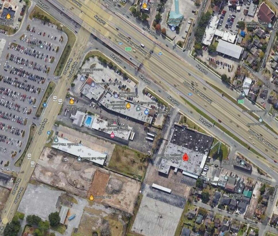
5815 Gulf Fwy Houston, TX 77023
DESIGNER twenty20studio, LLC contact: Ramon Gisbert 1407 Hawthorne Street Houston, TX 77006 t: 346.388.3820
GENERAL CONTRACTOR Custom Practices contact: Trevor Fawcett 1407 Hawthorne Street Houston, TX 77006 t: 713.836.2811
MEP ENGINEER Solutions Engineering contact: Duwan Cotton, PE 6101 Long Drive Houston, TX 77087 t: 713.376.9801
TAS / TDLR Otten Consulting Group contact: Kathy Rodriguez 2825 Wilcrest Dr #608 Houston, TX 77042 t: 713.975.1029

Rosenberg Richmond Greatwood Pleak Beasley Kendleton Orchard Simonton st. Bernard Wallis Fulshear Sugar Land Mission Bend Cinco Ranch Katy Brookshire Pattison Meadows Place Missouri City Fresno Sienna Plantation Manvel Pearland Friendswood League City Webster Seabrook Kemah La Porte Deer Park Pasadena Bellaire Channelview Baytown Beach City Mont Belvieu Cove Old River-Winfree Crosby Highlands Sheldon Stilson Dayton Kenefick Eastgate Huffman Atascocita Humble Porter New Caney Woodbranch Spring The Woodlands Hufsmith Pinehurst Tomball Cypress Jersey Village Aldine Hockley Waller Prairie View Pine Island Monaville Field Stone Houston 5815 Gulf Fwy Houston, TX 77023 P1.0SEWER & WATER PLAN P1.1AIR & VAC PLAN P1.2N2O PLAN P1.3PLUMBING DETAILS P1.4PLUMBING DETAILS P1.5PLUMBING DETAILS M1.0MECHANICAL PLAN M1.1ROOF PLAN M1.2MECHANICAL DETAILS E1.0POWER PLAN E1.1LIGHTING PLAN E1.2ONE-LINE & PANEL SCHEDULE A0COVER PAGE A0.0LIFE SAFETY PLAN A1.0DEMO PLAN A1.1OVERALL FLOOR PLAN A1.2EQUIPMENT PLAN A1.3DIMENSION
A1.4REFLECTED
SCHEDULEELEVATIONS
A6.2FINISH
ARCHITECTURE MECHANICAL ELECTRICAL PLUMBING
PLAN
CEILING PLAN A2.0INTERIOR ELEVATIONS A2.1INTERIOR ELEVATIONS A2.2INTERIOR ELEVATIONS A2.3INTERIOR ELEVATIONS A2.5CASEWORK TYPES/ DETAILS A4.0ENLARGED PLAN A6.0OPENING
A6.1FINISH WALL PLAN
SCHEDULE
Checked By: Drawn By: Sheet Name/Number: Project Team: Issue Revisions: Plot Date: Project Name/Number: SCALE: © Copyright 2021 All information, drawn, written, or implied, appearing in this document constitutes the original and unpublished work of twenty20 Studio, LLC. and may not be duplicated, distributed, or disclose by any means without the prior written consent of twenty20 Studio, LLC. This is an instrument of services and sole property of the author. The use of this document shall be revoked any of the design intent or the construction methods shown herein are not adhered to, or the terms of the contractual agreement for its use violated. Written dimensions on these drawings shall have precedence over scale dimensions. Contractors shall be responsible for al dimensions and conditions on the job. twenty20 Studio, LLC must be notified of any variation from the dimension and conditions shown by these drawings. Contractor: MEP: A B C D E F G 1 2 3 4 5 6 7 8 9 10 1 2 3 4 5 6 7 8 9 10 Designer: twenty20Studio, LLC Contact: Ramon Gisbert t: 346.388.3820 formerly RJG Design Studio, LLC 5815 Gulf Fwy Houston, TX 77023 Sheet Size: 24" x 36" RJG SA. Aftab Ur Rahman 21027 ARCHITECTURE + PLANNING studio TAS TDLR Otten Consulting Group Contact: Kathy Rodriguez t: 713.975.1029 Solution Engineering Contact: Duwan Cotton, PE t: 713.376.9801 Custom Practices Contact: Trevor Fawcett t: 713.836.2811 Safari Family Dental PERMIT 9/22/2022 NTS 14/11/2022 4:10:00 pm COVER PAGE A0
NTS 2 Vicinity Map
3.
classified companies.
Screws - Type S self-tapping screws, 1-1/4 or 2 in. long, (1 Hr) and 2-1/2 in. long (2 Hr). 4. Building Units* - For 1 Hr Rating - Nom 5/8 or 3/4 in. thick, 4 ft wide, faced gypsum wallboard panels with the faced side on the interior wall 5. cavity. Panels attached to studs and floor and ceiling runners with screws spaced 8 in. OC along the edges of the panel and 12 in. OC in the ield
REF. A A A. Life Safety Floor Plan Occupancy Group IIB Business Maximum exit travel distance = 80' feet B. Travel distance C. 2 total fire extinguisher locations, w/ a maximum o 150' between locations (occupants may be no more than 75' distance from an extinguisher). XX' F.E. BUILDING CODE SUMMARY APPLICABLE CODES CONSTRUCTION TYPE IIB TENANT FINISH AREA sq. ft. BUILDING HEIGHT 1 STORY OCCUPANT LOAD FACTOR 1 OCCUPANT/ 100 sq.ft. OCCUPANT LOAD 31 EXIT REQUIRED 2 EXITS REQUIRED 2 EXITS PROVIDED SPRINKLER FIRE ALARM 2012 IBC with City of Houston Amendments 2012 UMC - Uniform Mechanical Code 2012 UPC - Uniform Plumbing Code 2020 NEC - National Electrical Code 2012 IFC - International Fire Code 2015 IECC or ASHRAE 90.1 – 2013 NO NO 3119 DRYWALL METAL STUD PARTITION 1-HR PARTITION WHERE NOTED AS UL465 Long leg runner, 3" deep. Secure to deck @ 24" O.C. Underside of structural deck Scheduled ceiling TYPE "A" HEAD PLAN BASE Mtl. studs @ 16" O.C. See chart for size 5/8" Gyp. board each side Hold gyp. board above floor min. 1/8", max 3/8" Mtl. stud runner anchored to floor @ 24" O.C. Verify Scheduled Ceiling Height Varies Scheduled base Sound batts 1 Hour Tenant separation wall/1 Hour fire rated wal with insulation 6" Stud. To deck UL 263 A1 3 5/8" 4 7/8" 40 49 A2 6" 7 1/4" --/ -PARTITION TYPE STUD SIZE PART THICKNESS STC HORIZONTAL SECTION Floor and ceiling Runners - (Not Shown) - Channel-shaped runners, 3-5/8 in. wide (min), 1-1/4 in. Legs, formed from No. 25 MSG (min) galv teel, attached to floor and ceiling with fasteners spaced 24 in. OC, max. 1. Steel Studs - Channel - shaped 3-5/8 in. wide (min), 1-1/4 in. Legs, 3/8 in. folded back returns, formed from No. 25 MSG (min) galv steel, spaced 24 in. OC max. 2. Batts and Blankets*- (Optional, not shown) - Mineral wool or glass fiber batts partially or completely filling stud cavity. See batts and blankets (BZJZ) category for names of
of the panel. Joints oriented vertically and staggered on opposite sides of the assembly. General Electric Company - Type CoreGuard. National Gypsum Co., Charlotte, NC - Type Gold Bond Fire-Shield Type X Hi-Impact Wallboard or Gold Bond Fire-Shield Type X Kal-Kore Hi-Impact Plaster Base. Joint Tape and Compound - (not shown) - Vinyl, dry or premixed joint compound, applied in two coats to joints and screw heads; paper tape 2 n. wide, embedded in first layer of compound over all joints. 6. Wallboard, Gypsum* - For 2 Hr Rating any Classified 5/8 in. thick (minimum), 4 ft wide, wall board applied over exterior face of building Unit Item 5). Wallboard to be applied vertically with joints staggered 24 in. from Building Unit (Item 5) and attached to studs and floor and ceiling runners with screws spaced 8 in. OC. 7. See Wallboard, Gypsum (CKNX) Category for names of manufacturers *Bearing the UL Classification Marking 1-HOUR TENANT SEPARATION WALL Design No. U495 Nonbearing Wall Rating -1 or 2 HR. (See Items 5 and 7) 2 4 5 7 DRYWALL METAL STUD PARTITION TYPE "B" 3 1/2" Stud. With insulation (Not to deck) Sound attenuation batts Stagger any boxes or fixtures in the wall HEAD PLAN BASE Continous sound seal tape Sealant, continous Continous sound batts over partition Schedule ceiling Underside of structural deck PARTITION TYPESTUD SIZEPART THICKNESS B1 3 5/8" 4 7/8" STC 40 49 B26" 7 1/4" --/ -Sound batts TYPE "C" BASE Existing exterior wall HEAD PLAN Schedule ceiling Acoustical sealant @ all base joints 7/8" Furring hat channel Tenant side 1 1/2" Channel stud. Againts CMU or Concrete C1 1 1/2"2 1/8" --/ -C2 3 5/8"4 1/4" --/ -PARTITION TYPESTUD SIZEPART THICKNESS STC TYPE "D" Half Wall Stagger any boxes or fixtures in the wall PLAN BASE PARTITION TYPESTUD SIZEPART THICKNESS D13 5/8" 4 7/8" STC 40 49 Dry wall top HEAD Treat 03 Treat 02 Treat 01 Exam 02 Exam 01 R. R. 1 Waiting Reception Hallway 01 PAN CEPHTreat 04Treat 05 Hallway 02 Hallway 02 Hallway 02 Staff N2O IT MECH R. R. 2 Storage Steril LAB Office Marketing Billing Billing B1 B1 B1 B1 B1 B1 B1 B1 B1 B1 B1 B1 B1 B1 B1 B1 B1 B1 B1 TOTAL D I STANCE = 130 FT 3 I N F E F.E B1 B1 B1 B1 B1 B1 B1 B1 B1 Partition Type B B NTS Partition Type C C NTS Partition Type D D NTS Partition Type A A NTS NOT AN AMBULATORY CARE FACILITY ALL INDIVIDUALS AND PATIENTS ARE CAPABLE OF SELF-PRESERVATION AND CAN RESPOND AS AN INDIVIDUAL TO AN EMERGENCY SITUATION. N 1/4" = 1'-0"1 Life Safety Plan Checked By: Drawn By: Sheet Name/Number: Project Team: Issue Revisions: Plot Date: Project Name/Number: SCALE: © Copyright 2021 All information, drawn, written, or implied, appearing in this document constitutes the original and unpublished work of twenty20 Studio, LLC. and may not be duplicated, distributed, or disclose by any means without the prior written consent of twenty20 Studio, LLC. This is an instrument of services and sole property of the author. The use of this document shall be revoked any of the design intent or the construction methods shown herein are not adhered to, or the terms of the contractual agreement for its use violated. Written dimensions on these drawings shall have precedence over scale dimensions. Contractors shall be responsible for al dimensions and conditions on the job. twenty20 Studio, LLC must be notified of any variation from the dimension and conditions shown by these drawings. Contractor: MEP: A B C D E F G 1 2 3 4 5 6 7 8 9 10 1 2 3 4 5 6 7 8 9 10 Designer: twenty20Studio, LLC Contact: Ramon Gisbert t: 346.388.3820 formerly RJG Design Studio, LLC 5815 Gulf Fwy Houston, TX 77023 Sheet Size: 24" x 36" RJG SA. Aftab Ur Rahman 21027 ARCHITECTURE + PLANNING studio TAS TDLR Otten Consulting Group Contact: Kathy Rodriguez t: 713.975.1029 Solution Engineering Contact: Duwan Cotton, PE t: 713.376.9801 Custom Practices Contact: Trevor Fawcett t: 713.836.2811 Safari Family Dental PERMIT9/22/2022 As indicated 14/11/2022 4:10:02 pm LIFE SAFETY PLAN A0.0
REF. A A 10'0" 11' 6" 11' 6" 6'0" 68 110 110 110 " 110 Exam 01 Exam 02 Treat 01 Treat 02 Treat 03 Staff MECH IT N2O Treat 04 Treat 05 3' 9 1/2" 4'6" 3' 11 3/4" C D Waiting PAN CEPH Hallway 02 R. R. 1 Hallway 01 Billing 5' 0" 6' 4 3/4" 5' 0" 12' 10 3/4" 2' 0" 5 - 10 R. R. 2 4'4" 7'2" LAB Office 5 - 0 Reception 4' 0" 3'0" 1 - 6" Storage 6' - 8" 40 110 10 - 0" 6' 5 1/2" 21' 2 1/2" 5'0" 1 2 10 10 10 Steril 12 15 15 15 15 8 15 10 10 10 10 10 1 2 Marketing Hallway 02 Hallway 02 10 10 15 15 10 3 10 10 11 10 10 1/4" = 1'-0"1 Overall 1st Floor Plan N Checked By: Drawn By: Sheet Name/Number: Project Team: Issue Revisions: Plot Date: Project Name/Number: SCALE: © Copyright 2021 All information, drawn, written, or implied, appearing in this document constitutes the original and unpublished work of twenty20 Studio, LLC. and may not be duplicated, distributed, or disclose by any means without the prior written consent of twenty20 Studio, LLC. This is an instrument of services and sole property of the author. The use of this document shall be revoked any of the design intent or the construction methods shown herein are not adhered to, or the terms of the contractual agreement for its use violated. Written dimensions on these drawings shall have precedence over scale dimensions. Contractors shall be responsible for al dimensions and conditions on the job. twenty20 Studio, LLC must be notified of any variation from the dimension and conditions shown by these drawings. Contractor: MEP: A B C D E F G 1 2 3 4 5 6 7 8 9 10 1 2 3 4 5 6 7 8 9 10 Designer: twenty20Studio, LLC Contact: Ramon Gisbert t: 346.388.3820 formerly RJG Design Studio, LLC 5815 Gulf Fwy Houston, TX 77023 Sheet Size: 24" x 36" RJG SA. Aftab Ur Rahman 21027 ARCHITECTURE + PLANNING studio TAS TDLR Otten Consulting Group Contact: Kathy Rodriguez t: 713.975.1029 Solution Engineering Contact: Duwan Cotton, PE t: 713.376.9801 Custom Practices Contact: Trevor Fawcett t: 713.836.2811 Safari Family Dental PERMIT9/22/2022 1/4" = 1'-0" 14/11/2022 4:10:04 pm
FLOOR PLAN A1.1
ValueKey note Text Keynotes 2 3 Overall Plan 1 Blocking for wall hung sink Provide (2) 2 x 12 blocking for Pan/ Ceph
Remote Exposure 6 Shut-off for Air & Vac
Surface mounted electrical panels
Angle stop
washout Note: add
on
&
to be weather
jambs
Blocking for grab bars
Feature wall
Blocking for TV
for sign
Blocking for IT equipment
Blocking for barndoor track
existing door new location 15Blocking for dental light
OVERALL
Key
5
7
8
w/
sound board
walls, ceiling
door
stripped @ head
4
9
10
11Blocking
12
13
14Salvaged
REF. A A OP-1 Treat 03 Treat 02 Treat 01 Exam 02 Exam 01 Waiting Marketing Billing Reception Billing Hallway 01 PAN CEPH Treat 04 Treat 05 Hallway 02 Hallway 02 Hallway 02 Steril StorageLAB Office MECH IT N2O Staff EQ-1 EQ-1 EQ-1 EQ-1 EQ-1 GC-14 OP-6 GC-12 GC-11 IT-2 IT-2 IT-2 IT-2 IT-2 IT-2 IT-2 IT-2 EQ-7 EQ-1 EQ-10 EQ-1 EQ-10 IT-2 IT-2 IT-2 EQ-5 GC-9 EQ-11 GC-14 OP-6 GC-12 GC-11 EQ-2 EQ-10 EQ-10 EQ-10 EQ-10 EQ-10 OP-3 GC-9 GC-1 GC-15 GC-15 IT-1 IT-1 IT-1 IT-1 IT-1 IT-1 IT-1 IT-1 IT-1 IT-1 IT-1 IT-1 IT-1 IT-1 EQ-9 EQ-9 EQEQ-9 EQ-3 EQ-4 EQ-9 EQ-9 EQ-9 OP-8 OP-8 S-1 1/4" = 1'-0"2 Equipment Plan N Checked By: Drawn By: Sheet Name/Number: Project Team: Issue Revisions: Plot Date: Project Name/Number: SCALE: © Copyright 2021 All information, drawn, written, or implied, appearing in this document constitutes the original and unpublished work of twenty20 Studio, LLC. and may not be duplicated, distributed, or disclose by any means without the prior written consent of twenty20 Studio, LLC. This is an instrument of services and sole property of the author. The use of this document shall be revoked any of the design intent or the construction methods shown herein are not adhered to, or the terms of the contractual agreement for its use violated. Written dimensions on these drawings shall have precedence over scale dimensions. Contractors shall be responsible for al dimensions and conditions on the job. twenty20 Studio, LLC must be notified of any variation from the dimension and conditions shown by these drawings. Contractor: MEP: A B C D E F G 1 2 3 4 5 6 7 8 9 10 1 2 3 4 5 6 7 8 9 10 Designer: twenty20Studio, LLC Contact: Ramon Gisbert t: 346.388.3820 formerly RJG Design Studio, LLC 5815 Gulf Fwy Houston, TX 77023 Sheet Size: 24" x 36" RJG SA. Aftab Ur Rahman 21027 ARCHITECTURE + PLANNING studio TAS TDLR Otten Consulting Group Contact: Kathy Rodriguez t: 713.975.1029 Solution Engineering Contact: Duwan Cotton, PE t: 713.376.9801 Custom Practices Contact: Trevor Fawcett t: 713.836.2811 Safari Family Dental PERMIT9/22/2022 1/4" = 1'-0" 14/11/2022 4:10:06 pm
A1.2 Key ValueKey note Text Keynotes GC -1 OP -1 OP -2 OP -3 Owner provided Under Cab Ref. Microwave Refrigerator EQ -1 EQ -2 EQ -3 EQ -4 EQ -5 EQ -6 EQ -7 Equipment specialist provided Dental Chair Autoclave Air Compressor Vacuum Pump Model Trimmer Plaster Trap Pan/Ceph General contractor provided Reception cabinet IT-1 IT-2 T.V. IT specialist provided Computers GC -2 Coffee/Tech bar GC -3 Digital cabinet GC -4 R.R. cabinet GC -5 Lab. cabinet GC -7 Steril. cabinet OP -4 Desk GC -8 Sink GC -9 Lavatory GC -10 Toilet tissue dispenser Toilet GC -11 Staff cabinet GC -12 Sign contractor S-1Sign Storage shelves GC -13 IT-3 Tiny computer IT-4IT equipment OP -5 Mobile cart EQ -8Shelf A/V EQ -9Dental Light Grab bars GC -14 OP -6 Toilet Paper OP -7 Mobile cart Paper Towel OP -8 12 o' clock unit EQ -10 Sterilization Sink EQ -11 Mirrors GC -15
EQUIPMENT PLAN
REF. A A Treat 03 Treat 02 Treat 01 Exam 02 Exam 01 R. R. 1 Waiting Reception Hallway 01 Treat 04 PAN CEPH Treat 05 Billing Hallway 02 Storage LAB Office Staff R. R. 2 MECH IT N2O 37' 7 1/2" 3' 9 1/2" 7' 8" 11' 6 1/2" 7' 8" 6' 11 1/4" 3'11 3/4" 4'2 1/4" 4'11" 6'5" 6'9 1/2" 5'5" 10'5" 26'7 1/2" 68'8 3/4" 70'1 3/4" 9' 6" 10' 1 1/4" 10' - 3 1/2" 10'9 1/4" 40 - 0" 2'4 3/4" 29' - 10 3/4" 9' 1 1/4" 813 3/4 " 2310 1/2 60 37 1/2 50 37 411 38 50 1/2 69 1/2 5 '2 1/2 33 1/2 51 1/4 34 3/4 410 211 3/4 " 71 177 1/4 115 110 10705 28 1/4 26 15 1/4 7 15 1/4 6 3/4 1 - 6" 4 10 - 0 11 - 0" 6 3/4 " 15 1/2 " 15 1/2 6 1/2 3 - 11/4 31/2" 7 - 11" 7' 2 1/2" 3' 0" 5 - 0" 5'0" 1'6" 1'0" 1'8" 3' - 2 1/2" 4' 0" 20' 2 1/2" 11' - 6" 11' 11" 4' 9 3/4" 9' 6" 2' - 11 3/4" 1' 6" 8'0" 8'4" 31 2 - 5" 60 1/2 " 5'0" 1' 3" 9' - 0" 3' 2" 9' 0" 7' 11 1/4" 5' 9 1/4" 9' - 1 1/2" 7' 6" 4' 0" 8' - 6 3/4" 2' 0" 1' 0" 9' 9 1/2" 2'6" 6' 5 1/2" 4' 6 1/2" 13' 4 1/2" 2' 5" 7' 1" 2'0" 4'4" 2' 9" 25 3/4 40 64 3/4 2'0" 63' 4 3/4" 7' 2 1/2" A2.0 1 A2 0 2 A2.0 3 A2.0 4 A2.0 5 A2.0 6 A2 0 7 A2.3 9 A2 1 5 A2 2 5 - A22 4A2.1 3 A2.1 2 A2.2 10 A2.2 11 A2.2 12 A2.2 1 A2.2 8 A2.1 7 A2.1 8 9" 6'8" 115 115 " A4.0 1 A4.0 2 A2 3 2 A23 3 A2 3 4 A23 1 A2.3 7 A2.3 6 A2.3 5 A2.3 8 A2 2 3 A2 1 9 A2.1 10 3' 0" Steril 1 - 4" 36 4' - 10 1/4" 1' 10 1/4" 4' - 7 1/4" 3 - 51/4 12'0" 9'0" 2' 0" Marketing A2.3 12 A2 2 3 A2 2 3 A2 2 3 A2 2 3A2.2 3 A2.2 3 A2 2 5 A2 2 5 A2 2 5 A2 2 5 A2.2 5 A2.2 5 A22 4 A22 4 A22 4 A22 4 A2.2 4 A2.2 4 Hallway 02 Hallway 02 Hallway 02 Hallway 01 Waiting Hallway 01 Billing 5'1 1/4" 1/4" = 1'-0"1 Dimension Plan N Checked By: Drawn By: Sheet Name/Number: Project Team: Issue Revisions: Plot Date: Project Name/Number: SCALE: © Copyright 2021 All information, drawn, written, or implied, appearing in this document constitutes the original and unpublished work of twenty20 Studio, LLC. and may not be duplicated, distributed, or disclose by any means without the prior written consent of twenty20 Studio, LLC. This is an instrument of services and sole property of the author. The use of this document shall be revoked any of the design intent or the construction methods shown herein are not adhered to, or the terms of the contractual agreement for its use violated. Written dimensions on these drawings shall have precedence over scale dimensions. Contractors shall be responsible for al dimensions and conditions on the job. twenty20 Studio, LLC must be notified of any variation from the dimension and conditions shown by these drawings. Contractor: MEP: A B C D E F G 1 2 3 4 5 6 7 8 9 10 1 2 3 4 5 6 7 8 9 10 Designer: twenty20Studio, LLC Contact: Ramon Gisbert t: 346.388.3820 formerly RJG Design Studio, LLC 5815 Gulf Fwy Houston, TX 77023 Sheet Size: 24" x 36" RJG SA. Aftab Ur Rahman 21027 ARCHITECTURE + PLANNING studio TAS TDLR Otten Consulting Group Contact: Kathy Rodriguez t: 713.975.1029 Solution Engineering Contact: Duwan Cotton, PE t: 713.376.9801 Custom Practices Contact: Trevor Fawcett t: 713.836.2811 Safari Family Dental PERMIT9/22/2022 1/4" = 1'-0" 14/11/2022 4:10:08 pm DIMENSION PLAN A1.3
Staff N2O IT MECH LAB Storage R. R. 2 Hallway 02 Treat 04 Treat 05 Treat 03 Treat 02 Treat 01 Exam 02 Exam 01 R. R. 1 Reception Waiting Billing PAN CEPH Office 10' 0" 10' - 0" 10' 0" 10' 0" 10' 0" 10' 0" 10' 0" 10' 0" 10' 0" 10' 0" 10' 0" 9' 0" 9' - 0" 9' 0" 10' - 0" 10' 0" 10' 0" 9' 0" Hallway 01 1 1 1 1 1 1 1 9' 0" 10' 0" 2' - 6" 3' 0" 1'0" R1 -6 R2 -6 9' - 0" 10' - 0" 10' 0" 3 2 2 4 3 5 11/4" 11/4" 20 20 " 1 - 11/4" 20 1 - 11/4" 20 1'0" 5 - 0" 5 - 10" 5' 0" 1' 7 1/4" 9 1/2" 10' 0" 1'1" 2' 0" 1' 6 1/2" 1'2 1/2" 1' 1 1/2" 1'6" 1'6" R16 R1 ' -0 1 - 6" 4 4 4 4 4 4 4 34 " 34 38 30 36 3 - 9 2'3" 2'3" 3' 2 1/2" 1' 0" 3' 2" 1' 6" 3' 4" 3'7" 3'0" 3'0" 2'0" 1' 0" 4' 0" 1' - 0" 5 1/2" 2' 2 3/4" 8' 0" 10' 0" 5 5 5 5 6' 0" 6' 0" 5' - 0 1/2" 4'9 1/4" 4'5 1/2" 4'9 1/4" 6'7 3/4" 5 - 0 5 - 0 1 - 11/4 4 - 0 5' 6" 4'9 1/4" 5 9" 2' 0" 5 1/2" 1' - 6" 10 10 " 1 - 103/4 9 1/2" 4 3/4" 5 5 - 0" 4 - 0 66 3 / 4 1 - 6" 1/4" = 1'-0"1 RCP Key ValueKey note Text Keynotes 1Blocking for TV VTW Open Ceiling Checked By: Drawn By: Sheet Name/Number: Project Team: Issue Revisions: Plot Date: Project Name/Number: SCALE: © Copyright 2021 All information, drawn, written, or implied, appearing in this document constitutes the original and unpublished work of twenty20 Studio, LLC. and may not be duplicated, distributed, or disclose by any means without the prior written consent of twenty20 Studio, LLC. This is an instrument of services and sole property of the author. The use of this document shall be revoked any of the design intent or the construction methods shown herein are not adhered to, or the terms of the contractual agreement for its use violated. Written dimensions on these drawings shall have precedence over scale dimensions. Contractors shall be responsible for al dimensions and conditions on the job. twenty20 Studio, LLC must be notified of any variation from the dimension and conditions shown by these drawings. Contractor: MEP: A B C D E F G 1 2 3 4 5 6 7 8 9 10 1 2 3 4 5 6 7 8 9 10 Designer: twenty20Studio, LLC Contact: Ramon Gisbert t: 346.388.3820 formerly RJG Design Studio, LLC 5815 Gulf Fwy Houston, TX 77023 Sheet Size: 24" x 36" RJG SA. Aftab Ur Rahman 21027 ARCHITECTURE + PLANNING studio TAS TDLR Otten Consulting Group Contact: Kathy Rodriguez t: 713.975.1029 Solution Engineering Contact: Duwan Cotton, PE t: 713.376.9801 Custom Practices Contact: Trevor Fawcett t: 713.836.2811 Safari Family Dental PERMIT9/22/2022 1/4" = 1'-0" 14/11/2022 4:10:09 pm REFLECTED CEILING PLAN A1.4 Blocking for Dental Light Flushed in ceiling 6.5" speaker 2 3 4 5
A. Field verify all dimensions and conditions.
B. Provide matching filler pieces scribed to abutting surfaces where cabinet is indicate to be abutting adjacent surfaces or dissimilar materials or construction
C. Close all perimeter joints between cabinets, countertops, splashes, sinks, trim, dissimilar materials and finishes with sealant.
D. Finish all visible surfaces of cabinets, countertops, knee spaces, end panels, etc.
E. Scheduled room base finish to be applied continuously around all assembly items including knee spaces, cabinets, and panels, toe-boards, etc.
F. It is the design intent that all door and drawer faces be flush with the face of filler panels and scribes. Provided filler panels, wall scribes, finished fur downs, and all other components flush with the faces of doors and drawers.
G. Provide grommets, 1 ¾ diameter, unless otherwise noted in all plastic laminate countertops with knee spaces, at 30 o.c., to be field located.
H. Dimensions indicated are nominal industry standards for manufactured wood or plastic laminate cabinets. Manufactured steel cabinets are similar.
I. Provide a 2 valance when a task light is indicated U.N.O.
J. All cabinets are to be [plywood/mdf] with [plastic laminate] U.N.O.
K. Refer to Finish Schedule for cabinet and countertop finish materials.
PL1 PL1 PL1 PL1A SS SS PL1A PL1 PL1 SS PL1A Q1 SS PL1A PL1 PL1A OPEN Q1 Q1 PL1 PL1A PL1A SS PL1 PL1A PL1A SS PL1 SS SS PL1
1'0" 4'6" 2'6" 1'6" 2' 7 1/4" 2' 7 1/2" 2' - 7 1/2" 2' 7 1/2" 3' 6" 4'6" 1' 0" 4'6" 8' 0" 1' 6" 1'0" 2'6" 2'6" 2' 9" 2' 9" 2' 9" 2' - 9" 2'6" 2'6" 3'6" 2' 0" 11' 2 3/4" 2' 1" 4'6" 1'0" 2'6" LVT Note: GC to provide cabinet shop drawings for owner approval Checked By: Drawn By: Sheet Name/Number: Project Team: Issue Revisions: Plot Date: Project Name/Number: SCALE: © Copyright 2021 All information, drawn, written, or implied, appearing in this document constitutes the original and unpublished work of twenty20 Studio, LLC. and may not be duplicated, distributed, or disclose by any means without the prior written consent of twenty20 Studio, LLC. This is an instrument of services and sole property of the author. The use of this document shall be revoked any of the design intent or the construction methods shown herein are not adhered to, or the terms of the contractual agreement for its use violated. Written dimensions on these drawings shall have precedence over scale dimensions. Contractors shall be responsible for al dimensions and conditions on the job. twenty20 Studio, LLC must be notified of any variation from the dimension and conditions shown by these drawings. Contractor: MEP: A B C D E F G 1 2 3 4 5 6 7 8 9 10 1 2 3 4 5 6 7 8 9 10 Designer: twenty20Studio, LLC Contact: Ramon Gisbert t: 346.388.3820 formerly RJG Design Studio, LLC 5815 Gulf Fwy Houston, TX 77023 Sheet Size: 24" x 36" RJG SA. Aftab Ur Rahman 21027 ARCHITECTURE + PLANNING studio TAS TDLR Otten Consulting Group Contact: Kathy Rodriguez t: 713.975.1029 Solution Engineering Contact: Duwan Cotton, PE t: 713.376.9801 Custom Practices Contact: Trevor Fawcett t: 713.836.2811 Safari Family Dental PERMIT9/22/2022 As indicated 14/11/2022 4:10:12 pm INTERIOR ELEVATIONS A2.0 3/8" = 1'-0"1 Reception 1 -1 3/8" = 1'-0"2 Reception 1 -2 3/8" = 1'-0"3 Reception 1 -3 3/8" = 1'-0"4 Reception 1 -4 3/8" = 1'-0"5 Reception 1 -5 3/8" = 1'-0"6 Reception 1 -6 3/8" = 1'-0"7 Reception 1 -7 8 Reception Perspective View 1
A. Field verify all dimensions and conditions.
B. Provide matching filler pieces scribed to abutting surfaces where cabinet is indicate to be abutting adjacent surfaces or dissimilar materials or construction
C. Close all perimeter joints between cabinets, countertops, splashes, sinks, trim, dissimilar materials and finishes with sealant.
D. Finish all visible surfaces of cabinets, countertops, knee spaces, end panels, etc.
E. Scheduled room base finish to be applied continuously around all assembly items including knee spaces, cabinets, and panels, toe-boards, etc.
F. It is the design intent that all door and drawer faces be flush with the face of filler panels and scribes. Provided filler panels, wall scribes, finished fur downs, and all other components flush with the faces of doors and drawers.
G. Provide grommets, 1 ¾ diameter, unless otherwise noted in all plastic laminate countertops with knee spaces, at 30 o.c., to be field located.
H. Dimensions indicated are nominal industry standards for manufactured wood or plastic laminate cabinets. Manufactured steel cabinets are similar.
I. Provide a 2 valance when a task light is indicated U.N.O.
J. All cabinets are to be [plywood/mdf] with [plastic laminate]
PL1 OPEN PL1 OPEN PL1 PL1A PL1A PL1 PL1A PL1A PL1 PL1 PL1 PL1A PL1A PL1A PL1A PL1A PL1 PL1A PL1A
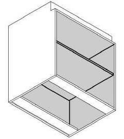
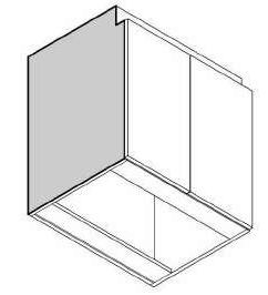
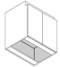
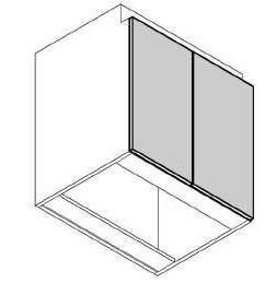
U.N.O. K. Refer to Finish Schedule for cabinet and countertop finish materials. LVT 2'6" 1' 6" 7' 7 1/2" 1' 6" 4' 10 3/4" 2'6" LVT 2'10" 3' 0" 5' 5 1/4" LVT 2' 7 1/2" 1' 10 1/2" 2'10" 2'6" 2'2" 2'6" 2'2" 2'10" 2' 8 1/2" 3' 10 1/4" 1' 6" 2'10" 3' 0" 1' 6" 2'10" LVT LVT Note: GC to provide cabinet shop drawings for owner approval Checked By: Drawn By: Sheet Name/Number: Project Team: Issue Revisions: Plot Date: Project Name/Number: SCALE: © Copyright 2021 All information, drawn, written, or implied, appearing in this document constitutes the original and unpublished work of twenty20 Studio, LLC. and may not be duplicated, distributed, or disclose by any means without the prior written consent of twenty20 Studio, LLC. This is an instrument of services and sole property of the author. The use of this document shall be revoked any of the design intent or the construction methods shown herein are not adhered to, or the terms of the contractual agreement for its use violated. Written dimensions on these drawings shall have precedence over scale dimensions. Contractors shall be responsible for al dimensions and conditions on the job. twenty20 Studio, LLC must be notified of any variation from the dimension and conditions shown by these drawings. Contractor: MEP: A B C D E F G 1 2 3 4 5 6 7 8 9 10 1 2 3 4 5 6 7 8 9 10 Designer: twenty20Studio, LLC Contact: Ramon Gisbert t: 346.388.3820 formerly RJG Design Studio, LLC 5815 Gulf Fwy Houston, TX 77023 Sheet Size: 24" x 36" RJG SA. Aftab Ur Rahman 21027 ARCHITECTURE + PLANNING studio TAS TDLR Otten Consulting Group Contact: Kathy Rodriguez t: 713.975.1029 Solution Engineering Contact: Duwan Cotton, PE t: 713.376.9801 Custom Practices Contact: Trevor Fawcett t: 713.836.2811 Safari Family Dental PERMIT9/22/2022 As indicated 14/11/2022 4:10:13 pm INTERIOR ELEVATIONS A2.1 1 Reception Perspective View 2 3/8" = 1'-0"2 Office 1 -1 3/8" = 1'-0"3 Office 1 -2 4 Office Perspective View 3/8" = 1'-0"5 Pan 1 -1 6 Pan Perspective View 3/8" = 1'-0"7 Steril 1 -1 3/8" = 1'-0"8 Steril 1 -2 3/8" = 1'-0"9 Steril 1 -3 3/8" = 1'-0"10 Steril 1 -4 11 Steril Perspective View 1 12 Steril Perspective View 2
A. Field verify all dimensions and conditions.
B. Provide matching filler pieces scribed to abutting surfaces where cabinet is indicate to be abutting adjacent surfaces or dissimilar materials or construction
C. Close all perimeter joints between cabinets, countertops, splashes, sinks, trim, dissimilar materials and finishes with sealant.
D. Finish all visible surfaces of cabinets, countertops, knee spaces, end panels, etc.
E. Scheduled room base finish to be applied continuously around all assembly items including knee spaces, cabinets, and panels, toe-boards, etc.
F. It is the design intent that all door and drawer faces be flush with the face of filler panels and scribes. Provided filler panels, wall scribes, finished fur downs, and all other components flush with the faces of doors and drawers.
G. Provide grommets, 1 ¾ diameter, unless otherwise noted in all plastic laminate countertops with knee spaces, at 30 o.c., to be field located.
H. Dimensions indicated are nominal industry standards for manufactured wood or plastic laminate cabinets. Manufactured steel cabinets are similar.
I. Provide a 2 valance when a task light is indicated U.N.O.
J. All cabinets are to be [plywood/mdf] with [plastic laminate] U.N.O.
PL1A PL1 PL1 PL1A PL1 PL1A PL1 PL1A OPEN PL1A PL1A PL1A PL1A PL1A PL1A PL1A PL1A
K. Refer to Finish Schedule for cabinet and countertop finish materials. 2'10" LVT 2'6" 2' 0" 5' - 0" 1' 6" 2' - 0" 1' 6" 2' 0" 2'6" LVT LVT 1' 3" 3' 0" 2' 0" 2'10" 2'2" 2'6" LVT 2'0" 1' 0" 1' - 0" 6' 9 1/2" 1' 6" 1' - 6" 3' 9 1/2" 1' 0" 1' 0" 1' 0" 2' 11" 7'0" 2'0" 2' 0" 2' - 0" 4' 9 1/2" 9' 9 1/2" 3' 0" 7'0" Checked By: Drawn By: Sheet Name/Number: Project Team: Issue Revisions: Plot Date: Project Name/Number: SCALE: © Copyright 2021 All information, drawn, written, or implied, appearing in this document constitutes the original and unpublished work of twenty20 Studio, LLC. and may not be duplicated, distributed, or disclose by any means without the prior written consent of twenty20 Studio, LLC. This is an instrument of services and sole property of the author. The use of this document shall be revoked any of the design intent or the construction methods shown herein are not adhered to, or the terms of the contractual agreement for its use violated. Written dimensions on these drawings shall have precedence over scale dimensions. Contractors shall be responsible for al dimensions and conditions on the job. twenty20 Studio, LLC must be notified of any variation from the dimension and conditions shown by these drawings. Contractor: MEP: A B C D E F G 1 2 3 4 5 6 7 8 9 10 1 2 3 4 5 6 7 8 9 10 Designer: twenty20Studio, LLC Contact: Ramon Gisbert t: 346.388.3820 formerly RJG Design Studio, LLC 5815 Gulf Fwy Houston, TX 77023 Sheet Size: 24" x 36" RJG SA. Aftab Ur Rahman 21027 ARCHITECTURE + PLANNING studio TAS TDLR Otten Consulting Group Contact: Kathy Rodriguez t: 713.975.1029 Solution Engineering Contact: Duwan Cotton, PE t: 713.376.9801 Custom Practices Contact: Trevor Fawcett t: 713.836.2811 Safari Family Dental PERMIT9/22/2022 As indicated 14/11/2022 4:10:15 pm INTERIOR ELEVATIONS A2.2 Note: GC to provide cabinet shop drawings for owner approval 3/8" = 1'-0"1 Lab 1 -1 2 Lab Perspective View 3/8" = 1'-0"3 12 o'clock Unit 1 -1 3/8" = 1'-0"4 12 o'clock Unit 1 -2 3/8" = 1'-0"5 12 o'clock Unit 1 -3 6 12 o'clock unit Perspective View 1 7 12 o'clock unit Perspective View 2 3/8" = 1'-0"8 Staff 1 -1 9 Staff Perspective View 3/8" = 1'-0"10 Storage 1 -1 3/8" = 1'-0"11 Storage 1 -2 3/8" = 1'-0"12 Storage 1 -3
A. Field verify all dimensions and conditions.
B. Provide matching filler pieces scribed to abutting surfaces where cabinet is indicate to be abutting adjacent surfaces or dissimilar materials or construction
C. Close all perimeter joints between cabinets, countertops, splashes, sinks, trim, dissimilar materials and finishes with sealant.
D. Finish all visible surfaces of cabinets, countertops, knee spaces, end panels, etc.
E. Scheduled room base finish to be applied continuously around all assembly items including knee spaces, cabinets, and panels, toe-boards, etc.
F. It is the design intent that all door and drawer faces be flush with the face of filler panels and scribes. Provided filler panels, wall scribes, finished fur downs, and all other components flush with the faces of doors and drawers.
G. Provide grommets, 1 ¾ diameter, unless otherwise noted in all plastic laminate countertops with knee spaces, at 30 o.c., to be field located.
H. Dimensions indicated are nominal industry standards for manufactured wood or plastic laminate cabinets. Manufactured steel cabinets are similar.
I. Provide a 2 valance when a task light is indicated U.N.O.
J. All cabinets are to be [plywood/mdf] with [plastic
Tile backer board,PTD Tile backer board,PTD Tile backer board,PTD Tile backer board,PTD Tile backer board,PTD Tile backer board,PTD Tile
board,PTD PL1A PL1 OPEN OPEN PL1 PL1A
backer
laminate] U.N.O. K. Refer to Finish Schedule for cabinet and countertop finish materials. 5'0" 2'10" 6 5 1 3 7 2 4 5'0" 2 3 7 4 5'0" 5'0" 2'10" 6 5 1 2'10" 6 5 3 1 2 4 5'0" 5'0" 3 7 2 3 4 5'0" 5'0" 2'10" 6 1 5 4 2'6" 1' 6" LVT FT FT LVT Note: GC to provide cabinet shop drawings for owner approval Checked By: Drawn By: Sheet Name/Number: Project Team: Issue Revisions: Plot Date: Project Name/Number: SCALE: © Copyright 2021 All information, drawn, written, or implied, appearing in this document constitutes the original and unpublished work of twenty20 Studio, LLC. and may not be duplicated, distributed, or disclose by any means without the prior written consent of twenty20 Studio, LLC. This is an instrument of services and sole property of the author. The use of this document shall be revoked any of the design intent or the construction methods shown herein are not adhered to, or the terms of the contractual agreement for its use violated. Written dimensions on these drawings shall have precedence over scale dimensions. Contractors shall be responsible for al dimensions and conditions on the job. twenty20 Studio, LLC must be notified of any variation from the dimension and conditions shown by these drawings. Contractor: MEP: A B C D E F G 1 2 3 4 5 6 7 8 9 10 1 2 3 4 5 6 7 8 9 10 Designer: twenty20Studio, LLC Contact: Ramon Gisbert t: 346.388.3820 formerly RJG Design Studio, LLC 5815 Gulf Fwy Houston, TX 77023 Sheet Size: 24" x 36" RJG SA. Aftab Ur Rahman 21027 ARCHITECTURE + PLANNING studio TAS TDLR Otten Consulting Group Contact: Kathy Rodriguez t: 713.975.1029 Solution Engineering Contact: Duwan Cotton, PE t: 713.376.9801 Custom Practices Contact: Trevor Fawcett t: 713.836.2811 Safari Family Dental PERMIT9/22/2022 As indicated 14/11/2022 4:10:17 pm INTERIOR ELEVATIONS A2.3 3/8" = 1'-0"1 R. R. 01-1 3/8" = 1'-0"2 R. R. 01-2 3/8" = 1'-0"3 R. R. 01-3 3/8" = 1'-0"4 R. R. 01-4 3/8" = 1'-0"5 R. R. 02-1 3/8" = 1'-0"6 R. R. 02-2 3/8" = 1'-0"7 R. R. 02-3 3/8" = 1'-0"8 R. R. 02-4 3/8" = 1'-0"9 Billing 1 -1 10 Marketing Perspective View 13 R. R. 1 Perspective View 14 R. R. 2 Perspective View 11 Billing Perspective View 3/8" = 1'-0"12 Marketing 1 -1 Key ValueKey note Text Keynotes 1 2 3 Lavatory Toilet Grab bar Paper Towel Mirror Vanity sconce selected by owner Toilet Papers 5 6 7 4
A. Field verify all dimensions and conditions.
B. Provide matching filler pieces scribed to abutting surfaces where cabinet is indicate to be abutting adjacent surfaces or dissimilar materials or construction
C. Close all perimeter joints between cabinets, countertops, splashes, sinks, trim, dissimilar materials and finishes with sealant.
D. Finish all visible surfaces of cabinets, countertops, knee spaces, end panels, etc.
E. Scheduled room base finish to be applied continuously around all assembly items including knee spaces, cabinets, and panels, toe-boards, etc.
F. It is the design intent that all door and drawer faces be flush with the face of filler panels and scribes. Provided filler panels, wall scribes, finished fur downs, and all other components flush with the faces of doors and drawers.
G. Provide grommets, 1 ¾ diameter, unless otherwise noted in all plastic laminate countertops with knee spaces, at 30 o.c., to be field located.
H. Dimensions indicated are nominal industry standards for manufactured wood or plastic laminate cabinets. Manufactured steel cabinets are similar.
I. Provide a 2 valance when a task light is indicated U.N.O.
J. All cabinets are to be [plywood/mdf] with [plastic laminate] U.N.O.
K. Refer to Finish Schedule for cabinet and countertop finish materials.
Base cabinet Double door w/ 2 drawers Adjustable shelf RE: Elev. 4" 2'10" 4" E Upper cabinet Single door 2'6" 4' 8 1/2" AFF RE: Elev. B Base cabinet Single door w/ drawer Blind corner Adjustable shelf Upper cabinet Double door @ sink 1'2" 6'0 1/2" AFF RE: Elev. Base cabinet Single door w/ drawer Adjustable shelf RE: Elev. 4" 2'10" 4" A A1 RE: Elev. RE: Elev. Solid surfacing countertop and splash 4" 2'10" 4" Upper cabinet Double door 2'6" 4' 8 1/2" AFF RE: Elev. F F1 Adjustable shelf Adjustable shelf Solid surfacing countertop and splash Solid surfacing countertop and splash Accessible sink cabinet RE: Elev. 2'1" 4" D 1' 8" min. 8" min. 1' 7" Solid surfacing countertop and splash 2'10" 2 '3" min Base cabinet Double door Adjustable shelf RE: Elev. 4" Sched. Height 4" B2 Solid surfacing countertop and splash Base cabinet Single door 4" 2'10" 4" B4 Adjustable shelf Solid surfacing countertop and splash RE: Elev. C 1' 8" 6" Drawer 4" 2'4 1/2" C1 1' 8" Drawer 4" 2' 8 1/2" Base cabinet Double door w/ 2 drawers Adjustable shelf RE: Elev. 4" 2'10" 4" B1 Solid surfacing countertop and splash Base cabinet Single door w/ 1 drawers Adjustable shelf RE: Elev. 4" 2'10" 4" B3 Solid surfacing countertop and splash EQ EQ EQ EQ 9" 9"
CABINET FACE CABINET FACE SURFACES ARE COVERED WITH VERTICAL GRADE HIGH-PRESSURE LAMINATE. COLOR TO MATCH FINISHED EXTERIOR CLOSED INTERIOR ALL INTERIOR SURFACES ARE MELAMINE (EXCEPT FOR DOORS). DOORS WILL HAVE CABINET LINER. UNLESS OTHERWISE SPECIFIED. OPEN INTERIOR EXPOSED INTERIOR SURFACES ARE COVERED WITH VERTICAL GRADE HIGH-PRESSURE LAMINATE COLOR TO MATCH FINISHED EXTERIOR. EXPOSED ENDS EXPOSED END SURFACES ARE COVERED WITH VERTICAL GRADE HIGH-PRESSURE LAMINATE. COLOR TO MATCH CABINET EXTERIOR. WALL BOTTOMS EXPOSED WALL BOTTOM SURFACES ARE COVERED WITH VERTICAL GRADE HIGH-PRESSURE LAMINATE. COLOR TO MATCH CABINET EXTERIOR. CABINET EDGING EXPOSED CABINET EDGES WILL HAVE 1mm PVC (NOMINAL). COLOR WILL MATCH CABINET EXTERIOR. DOOR DRAWER EDGING DOOR DRAWER EDGES WILL HAVE 1mm PVC (NOMINAL). COLOR WILL MATCH CABINET EXTERIOR. ADJUSTABLE SHELF EDGING CABINET INTERIOR SHELVES TO HAVE 1mm PVC FRONT EDGE. COLOR TO MATCH CABINET INTERIOR COLOR. CABINET SURFACES CABINET CORE MATERIAL CABINET BODY CORE CABINET BODY CORE MATERIAL IS 3/4" PARTICLE BOARD CABINET FACE CORE CABINET FACE CORE MATERIAL IS 3/4" PARTICLE BOARD DRAWER BOX 3/4" MELAMINE DRAWER SIDES & 1/4" BOTTOM FULLY CAPTURED. NTS Casework Legend Checked By: Drawn By: Sheet Name/Number: Project Team: Issue Revisions: Plot Date: Project Name/Number: SCALE: © Copyright 2021 All information, drawn, written, or implied, appearing in this document constitutes the original and unpublished work of twenty20 Studio, LLC. and may not be duplicated, distributed, or disclose by any means without the prior written consent of twenty20 Studio, LLC. This is an instrument of services and sole property of the author. The use of this document shall be revoked any of the design intent or the construction methods shown herein are not adhered to, or the terms of the contractual agreement for its use violated. Written dimensions on these drawings shall have precedence over scale dimensions. Contractors shall be responsible for al dimensions and conditions on the job. twenty20 Studio, LLC must be notified of any variation from the dimension and conditions shown by these drawings. Contractor: MEP: A B C D E F G 1 2 3 4 5 6 7 8 9 10 1 2 3 4 5 6 7 8 9 10 Designer: twenty20Studio, LLC Contact: Ramon Gisbert t: 346.388.3820 formerly RJG Design Studio, LLC 5815 Gulf Fwy Houston, TX 77023 Sheet Size: 24" x 36" RJG SA. Aftab Ur Rahman 21027 ARCHITECTURE + PLANNING studio TAS TDLR Otten Consulting Group Contact: Kathy Rodriguez t: 713.975.1029 Solution Engineering Contact: Duwan Cotton, PE t: 713.376.9801 Custom Practices Contact: Trevor Fawcett t: 713.836.2811 Safari Family Dental PERMIT9/22/2022 As indicated 14/11/2022 4:10:18 pm CASEWORK TYPES/ DETAILS A2.5

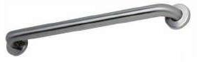
2" 50mm 3-1/8" 80mm -1/4" 55mm -5/8" 65mm 3-1/8" 80mm 2-1/4" 55mm 1-1/2" 38mm 3-1/4" 85mm Dia. -1/8" 80mm 5/16" 8mm Snap Flange Cover 42" 1065mm 4" 100mm 50" 1270mm 45-7/8" 1165mm 57-7/8" 1470mm Edge of Flange to Wall Edge of Flange to Wall 1 1/2" (38mm) Diameter Stainless Steel Grab Bars with Snap FLange B-6806 Safety Warning: Grab bars are no stronger than the anchors and walls to which they are attached and, therefore, must be firmly secured in order to support the loads for which they are intended. To avoid potential injury, the building owner or maintenance personnel should remove the grab bar from service if the grab bar is not adequately secured to wall or there is any observed damage to the welds. Note: Grab Bars shall resist a 250 LB Load in Any Point and direction. TWO-WALL TOILET COMPARTMENT BAR 42 x 54 B-6897 A2 3 2 A23 3 A2 3 4 A23 1 5'-0" Turning Radius 7 - 6 Min cearence 5 - 0 ADA Min c learence 50" ADA 68 1 2 7 5 3 4 34 3/4 30 4 A2.3 7 A2.3 6 A2.3 5 A2.3 8 5'-0" Turning Radius Min. clearence 5' - 0" ADA 6' 8" Min. clearence 5'0" ADA 7'2" 3 7 2 1 5 4 4'2 3/4" 3'0" 4" Grab Bar Mounting Kits Product ID WINGITS-MAW35 MOUNTING KITS - REFINED ENGINEERED SAFETY MASTER Anchor WingIts - World's Strongest FastenerTM - WingiIts are rated up to 300 lbs. (depending on application) and will neverLoosen, Millions of Installaions and No Issues. WingIts utilizes a # 8 stainless steel crew, which is ideal for installing Bath Accessories, Window Dressings and Shelving, Typical installations include Bath Accessories, Window Dressings,Mail Boxes, Hose Reels, Heavy Drapery Rods, Shelving, Cabinets, Pedestal Sinks, Dispensers, Coa Hooks, Railings, and for most Wall Mount Accesories with a base over 1 in, made in USA. Checked By: Drawn By: Sheet Name/Number: Project Team: Issue Revisions: Plot Date: Project Name/Number: SCALE: © Copyright 2021 All information, drawn, written, or implied, appearing in this document constitutes the original and unpublished work of twenty20 Studio, LLC. and may not be duplicated, distributed, or disclose by any means without the prior written consent of twenty20 Studio, LLC. This is an instrument of services and sole property of the author. The use of this document shall be revoked any of the design intent or the construction methods shown herein are not adhered to, or the terms of the contractual agreement for its use violated. Written dimensions on these drawings shall have precedence over scale dimensions. Contractors shall be responsible for al dimensions and conditions on the job. twenty20 Studio, LLC must be notified of any variation from the dimension and conditions shown by these drawings. Contractor: MEP: A B C D E F G 1 2 3 4 5 6 7 8 9 10 1 2 3 4 5 6 7 8 9 10 Designer: twenty20Studio, LLC Contact: Ramon Gisbert t: 346.388.3820 formerly RJG Design Studio, LLC 5815 Gulf Fwy Houston, TX 77023 Sheet Size: 24" x 36" RJG SA. Aftab Ur Rahman 21027 ARCHITECTURE + PLANNING studio TAS TDLR Otten Consulting Group Contact: Kathy Rodriguez t: 713.975.1029 Solution Engineering Contact: Duwan Cotton, PE t: 713.376.9801 Custom Practices Contact: Trevor Fawcett t: 713.836.2811 Safari Family Dental PERMIT9/22/2022 As indicated 14/11/2022 4:10:18 pm ENLARGED PLAN A4.0 3/8" = 1'-0"1 Enlarged R.R. 1 3/8" = 1'-0"2 Enlarged R.R. 2 Key ValueKey note Text Keynotes 1 2 3 Lavatory Toilet Grab bar 4Paper Towel 5Mirror 6Vanity sconce selected by owner 7Toilet Papers/Tissue Papers
Schedule
17Hallway 02R. R. 23'0"8'0"0'1 3/4"ALRe:Finishing Schedule
18StaffHallway 023'0"7'0"0'2"FRe:Finishing Schedule
19MECHStaff3'0"7'0"0'1 3/4"NoneRe:Finishing Schedule
20ITStaff3'0"7'0"0'1 3/4"NoneRe:Finishing Schedule
21N2OStaff3'0"7'0"0'2"FRe:Finishing Schedule
Note:
A readily visible durable sign is posted on the egress side on or adjacent to the main entry door stating: THIS DOOR TO REMAIN UNLOCKED WHEN BUILDING IS OCCUPIED. The sign shall be in letters 1 inch (2 mm) high on a contrasting background.
HARDWARE
1. All doors shall have lever handle 36" A.F.F., butt hinges, no closures, and passage set. restrooms shall have button type lock with key on outside. front entry doors are existing.
2. Hardware based on schlage 'A' series.
NOTUSED NOTUSED NOTUSED
REF. A A Schd. Height Schd. Width F Full Flush Schd. Height Schd. Width P Pocket Door Schd. Height Schd. Width M Metal Door BP Bypass Glass Door Schd. Width G Glass Half Lite 8" 6" 6" L Door w/ Louver Schd. Height Schd. Width 2" Cut for ventilation Schd. Width FG Full Glass 8" 6" 6" Schd. Height 1'1" 8" 1' 4" 8" 6" 8" Schd. Width Schd. Height Schd. Height Narrow Lite, 8" N8 Schd. Width Schd. Height EQ EQ 2" 2" HM Hollow Metal AL Aluminum 1 1/2" 1 1/2" Treat 03 Treat 02 Treat 01 Exam 02 Exam 01 R. R. 1 Waiting Reception Hallway 01 Hallway 01 Billing Billing Marketing Treat 05 Treat 04 PAN / CEPH Hallway 02 Hallway 02 Hallway 02 Hallway 02 Steril StorageLAB Office MECH IT N2O Staff R. R. 2 01 02 04 05 08 03 09 06 07 10 11 12 13 14 15 16 17 18 19 20 21 JUPITER 3-3/8" 11/16" 21/2" 4-1/2" Mark Width Height Frame Finish Frame type W1 Window Schedule 13' -7 3/4" 4'-0"ALMatch Door Frame Glass: 1/4" Tempered clear (See documents for placement) 1/4" = 1'-0" Door Types 1/4" = 1'-0" Frame Types Door Schedule Mark From Room: Name To Room: NameWidthHeightThickness Door Type Fire Rating Frame Type Frame Finish Door FinishHardware Schedule HW Set 01Waiting3'6 25/32" 7'11"0'1 3/4"NoneStorefront1,11 02Waiting2'10"7'11"0'1 3/4"NoneRe:Finishing Schedule 03Marketing3'0 13/32" 7'11"0'1 3/4"FGNoneRe:Finishing Schedule 04WaitingR. R. 13'0"8'0"0'1 3/4"ALRe:Finishing Schedule 05Hallway 01Waiting3'0"8'0"0'1 3/4"NoneRe:Finishing Schedule 06Exam 01Hallway 013'0"8'0"0'1 3/4"BPNoneStorefrontRe:Finishing Schedule 07Exam 02Hallway 013'0"8'0"0'1 3/4"BPNoneStorefrontRe:Finishing Schedule 08Hallway 01Billing3'0"7'0"0'2"FRe:Finishing Schedule 09Hallway 02Hallway 013'0"7'0"0'2"FRe:Finishing Schedule 10Treat 01Hallway 023'0"8'0"0'1 3/4"BPNoneStorefrontRe:Finishing Schedule 11Hallway 02Treat 043'0"8'0"0'1 3/4"BPNoneStorefrontRe:Finishing Schedule 12Hallway 02Treat 053'0"8'0"0'1 3/4"BPNoneStorefrontRe:Finishing Schedule 13Hallway 02Office3'0"7'0"0'2"FRe:Finishing Schedule 14Treat 02Hallway 023'0"8'0"0'1 3/4"BPNoneStorefrontRe:Finishing Schedule 15StorageLAB3'0"7'0"0'2"FRe:Finishing Schedule 16Treat 03Hallway 023'0"8'0"0'1 3/4"BPNoneStorefrontRe:Finishing
1/4" = 1'-0"1 Door Plan
1. DEADBOLT W/LOCK INDICATOR 2. LOCK 3. PASSAGE 4. PRIVACY LOCK 5. CLOSER 6. ALUM. RIM PANIC DEVICE 7. PEEP HOLE 8. DOOR SWEEP 9. WEATHER STRIPPING 10. STORAGE LOCK 11. CROSS BAR PANIC BAR EXIT DEVICE
Checked By: Drawn By: Sheet Name/Number: Project Team: Issue Revisions: Plot Date: Project Name/Number: SCALE: © Copyright 2021 All information, drawn, written, or implied, appearing in this document constitutes the original and unpublished work of twenty20 Studio, LLC. and may not be duplicated, distributed, or disclose by any means without the prior written consent of twenty20 Studio, LLC. This is an instrument of services and sole property of the author. The use of this document shall be revoked any of the design intent or the construction methods shown herein are not adhered to, or the terms of the contractual agreement for its use violated. Written dimensions on these drawings shall have precedence over scale dimensions. Contractors shall be responsible for al dimensions and conditions on the job. twenty20 Studio, LLC must be notified of any variation from the dimension and conditions shown by these drawings. Contractor: MEP: A B C D E F G 1 2 3 4 5 6 7 8 9 10 1 2 3 4 5 6 7 8 9 10 Designer: twenty20Studio, LLC Contact: Ramon Gisbert t: 346.388.3820 formerly RJG Design Studio, LLC 5815 Gulf Fwy Houston, TX 77023 Sheet Size: 24" x 36" RJG SA. Aftab Ur Rahman 21027 ARCHITECTURE + PLANNING studio TAS TDLR Otten Consulting Group Contact: Kathy Rodriguez t: 713.975.1029 Solution Engineering Contact: Duwan Cotton, PE t: 713.376.9801 Custom Practices Contact: Trevor Fawcett t: 713.836.2811 Safari Family Dental PERMIT9/22/2022 As indicated 14/11/2022 4:10:27 pm OPENING SCHEDULE / ELEVATIONS A6.0
Practices
Trevor Fawcett t: 713.836.2811
Engineering Contact: Duwan Cotton, PE t: 713.376.9801
TDLR Otten Consulting Group
Kathy Rodriguez t: 713.975.1029
REF. A A Treat 03 Treat 02 Treat 01 Exam 02 Exam 01 R. R. 1 Waiting Marketing Billing Hallway 01 Reception Treat 05 Treat 04 PAN CEPH Steril Storage Office LAB MECH IT N2O Staff R. R. 2 Hallway 02 1/4" = 1'-0"1 Paint Wall Plan Checked By: Drawn By: Sheet Name/Number: Project Team: Issue Revisions: Plot Date: Project Name/Number: SCALE: © Copyright 2021 All information, drawn, written, or implied, appearing in this document constitutes the original and unpublished work of twenty20 Studio, LLC. and may not be duplicated, distributed, or disclose by any means without the prior written consent of twenty20 Studio, LLC. This is an instrument of services and sole property of the author. The use of this document shall be revoked any of the design intent or the construction methods shown herein are not adhered to, or the terms of the contractual agreement for its use violated. Written dimensions on these drawings shall have precedence over scale dimensions. Contractors shall be responsible for al dimensions and conditions on the job. twenty20 Studio, LLC must be notified of any variation from the dimension and conditions shown by these drawings. Contractor: MEP: A B C D E F G 1 2 3 4 5 6 7 8 9 10 1 2 3 4 5 6 7 8 9 10 Designer: twenty20Studio, LLC Contact: Ramon Gisbert t: 346.388.3820 formerly RJG Design Studio, LLC 5815 Gulf Fwy Houston,
77023 Sheet Size: 24" x 36" RJG SA. Aftab Ur Rahman 21027 ARCHITECTURE + PLANNING studio TAS
Solution
Safari Family Dental PERMIT9/22/2022 1/4" = 1'-0" 14/11/2022 4:10:28 pm
WALL PLAN A6.1 FINISH SCHEDULE GENERAL FINISH SELECTIONS: Class-A Finishes, Typical WALL FINISH: Wall shall be painted with two coats of latex Sherwin Williams. Install water resistant gyp board on all wet walls. Level 4 finish with smooth roll -on texture PAINT: MFR.: STYLE: FIELD COLOR FC $8.50 PSF INSTALLED ALLOWANCE WALL TILE WT WALL FEATURE MFR.: STYLE: 1x1 CLEAR SEALED YELLOW PINE WS WT2 MFR.: FLOOR AND DECOR STYLE: 100112689 FESTIVAL BRIGHT WHITE ICE CERAMIC WALL TILE COLOR: WHITE WT1 MFR.: FLOOR AND DECOR STYLE: 100837033 COLOR: BLUE MFR.: STYLE: COLOR: NAVY BLUE AC1 MFR.: STYLE: SMALL DUMBO WALLPAPER BY CHRIS BENZ COLOR: NAVY WP1
TX
Contact:
Custom
Contact:
FINISH
2x2 Ceiling Tile: Certainteed BET-154 24x24x5/8 Reveal Beveled Baroque Grid: 15/16"
REF. A A PL2 PL2 PL1 PL1 PL1 PL1 PL1 PL1 PL1 PL1 Q1 PL2 PL1 PL2 Q1 PL1 PL1 PL1 PL1 PL1 PL1 PL1 LVT FT PL1 Q1 PL2 FT LVT LVT LVT LVT LVT LVT LVT LVT FT LVT LVT LVT LVT LVT LVT LVT Treat 03 Treat 02 Treat 01 Exam 02 Exam 01 R. R. 1 Waiting Reception Marketing Billing Billing Hallway 01 Treat 04Treat 05 PAN CEPH Hallway 02 Hallway 02 Hallway 02 Hallway 02 Hallway 02 Steril Office LAB Storage Staff MECH IT N2O R. R. 2 LVT 1/4" = 1'-0"1 Finish Floor Plan Floor Material Legend1/4" = 1'-0"3
SCHEDULE GENERAL FINISH SELECTIONS: Class-A Finishes, Typical DOORS: WILSONART HARDWARE MFR.: SCHLAGE OR EQUAL COLOR: DOOR FRAMES MFR.: RACO COLOR: FLOORING: MFR.: STYLE: LOC.: LVT WALL BASE: MFR.: STYLE: CEILING/SOFFIT: A. Hallway:
24x24x5/8
B. Rooms:
C.
CABINETS: MFR.: COLOR: STYLE: FACE OF RECEPTION DESK ST MFR.: STYLE: TRANSACTION TOP Q1 MFR.: STYLE: WRITING SURFACE PL1 MFR.: STYLE: UPPER & LOWER CABINETS: PL1A TILE: MFR.: STYLE: SIZE: GROUT: PATIENT RESTROOM FLOORING FT PL1A MFR.: STYLE: COUNTER-TOP PL2 MFR.: STYLE: LOC.: SS MFR.: STYLE: LOC.: PL2A STYLE: MELAMINE WHITE PANEL PL3 Checked By: Drawn By: Sheet Name/Number: Project Team: Issue Revisions: Plot Date: Project Name/Number: SCALE: © Copyright 2021 All information, drawn, written, or implied, appearing in this document constitutes the original and unpublished work of twenty20 Studio, LLC. and may not be duplicated, distributed, or disclose by any means without the prior written consent of twenty20 Studio, LLC. This is an instrument of services and sole property of the author. The use of this document shall be revoked any of the design intent or the construction methods shown herein are not adhered to, or the terms of the contractual agreement for its use violated. Written dimensions on these drawings shall have precedence over scale dimensions. Contractors shall be responsible for al dimensions and conditions on the job. twenty20 Studio, LLC must be notified of any variation from the dimension and conditions shown by these drawings. Contractor: MEP: A B C D E F G 1 2 3 4 5 6 7 8 9 10 1 2 3 4 5 6 7 8 9 10 Designer: twenty20Studio, LLC Contact: Ramon Gisbert t: 346.388.3820 formerly RJG Design Studio, LLC 5815 Gulf Fwy Houston, TX 77023 Sheet Size: 24" x 36" RJG SA. Aftab Ur Rahman 21027 ARCHITECTURE + PLANNING studio TAS TDLR Otten Consulting Group Contact: Kathy Rodriguez t: 713.975.1029 Solution Engineering Contact: Duwan Cotton, PE t: 713.376.9801 Custom Practices Contact: Trevor Fawcett t: 713.836.2811 Safari Family Dental PERMIT9/22/2022 1/4" = 1'-0" 14/11/2022 4:10:33 pm FINISH SCHEDULE A6.2
FINISH
2x2 Ceiling Tile: Certainteed BET-154
Reveal Beveled Baroque Grid: 15/16"
Restrooms, Mechanical rooms, and furr downs: Sheetrock ceiling painted
LEGEND:
TRANSFORMER DETAIL ABOVE CEILING
REF. A A Sign 1 B-1 F 2 B-21 44" 44" 44" C F 2 B-25 65" 44"44" C 72" F 2 B-27 65" 44"44" C 72" F 2 B-29 65" 44"44" C 72" F 2 65" 44" 44" C 72" B-11 F 2 65" 44" 44" C 72" B-13 3 6 A-40,42 3 4 For WH B-32,34 A-28,30,32 For RTU #1 A-34,36,38 For RTU #2 B-47 B-45 72" 36" 65" B-36,38 220 B-40,42 220 5 5 44" 65" 44" 44" B-31 36" 36" 36" 36" 44" 44" 44" Staff StorageLAB MECH N2O IT Hallway 02 Treat 03 Treat 02 Treat 01 Exam 02 Exam 01 Treat 05 Treat 04 Hallway 01 PAN CEPH Reception Waiting Billing R. R. 1 R. R. 2 Office Hallway 02 B-35 B-37 110 110 36" 36" 72" F 2 B-23 44" 44" 44" C 72" 84" B-17 B-19 110 220 B-15 B-5 36" 36" 36" 36" 36" 36" 36" 36" 36" 60" 36" 36" 36" 36" 36" 36" B-3 B-7 B-9 B-39 B-49 B-33 B-41 B-43 S S S S S S Steril 36"
CEILING OUTLET DUPLEX RECEPTACLE DEDICATED OUTLET; 110 V DATA JACK DOUBLE DUPLEX RECEPTACLE GROUND FAULT CURRENT INTERRUPTER RECEPTACLE (GFCI) Transf. ELEVATION PLAN Spring vibration isolators sized for weight of transformer Hang from top chord of joist at panel point ½" ⌀ Threaded rod (4 Req'd) 1 ½" Unistrut channel frame Bolt Transformer to be base channel (Typ. 4 places) Platform sized for individual transformer
1/4" = 1'-0" 1 Power Plan 2" CHASE UNDER FLOOR BETWEEN CHAIR, J-BOX AND REAR CABINET, TYP. GC TO PROVIDE COVER BOX FOR EQUIPMENT WIRES (TYP.) KEY NOTE 1 2 3 4 KEYNOTE TEXT SIGN POWER: DEDICATED 20 AMP, 120 VOLT CIRCUIT WITH A TIMER. ELECTRICAL SUB-CONTRACTOR TO RUN BRANCH CIRCUIT AND JUNCTION BOX TO THE BACK WALL OF THE SIGN. SEMI-RECESSED ELEC. PANEL PROVIDE BUCKBOOSTER FOR DENTAL EQUIPMENT 5 WATER HEATER LOCATED IN CEILING TRANSFORMER IN CEILING 6 Checked By: Drawn By: Sheet Name/Number: Project Team: Issue Revisions: Plot Date: Project Name/Number: SCALE: © Copyright 2021 All information, drawn, written, or implied, appearing in this document constitutes the original and unpublished work of twenty20 Studio, LLC. and may not be duplicated, distributed, or disclose by any means without the prior written consent of twenty20 Studio, LLC. This is an instrument of services and sole property of the author. The use of this document shall be revoked any of the design intent or the construction methods shown herein are not adhered to, or the terms of the contractual agreement for its use violated. Written dimensions on these drawings shall have precedence over scale dimensions. Contractors shall be responsible for al dimensions and conditions on the job. twenty20 Studio, LLC must be notified of any variation from the dimension and conditions shown by these drawings. Contractor: MEP: A B C D E F G 1 2 3 4 5 6 7 8 9 10 1 2 3 4 5 6 7 8 9 10 Designer: twenty20Studio, LLC Contact: Ramon Gisbert t: 346.388.3820 formerly RJG Design Studio, LLC 5815 Gulf Fwy Houston, TX 77023 Sheet Size: 24" x 36" RJG SA. Aftab Ur Rahman 21027 ARCHITECTURE + PLANNING studio TAS TDLR Otten Consulting Group Contact: Kathy Rodriguez t: 713.975.1029 Solution Engineering Contact: Duwan Cotton, PE t: 713.376.9801 Custom Practices Contact: Trevor Fawcett t: 713.836.2811 Safari Family Dental PERMIT 9/22/2022 As indicated 14/11/2022 4:10:34 pm POWER PLAN E1.0
LIGHTING FIXTURE SCHEDULE
TBD by Owner O1 TBD by Owner 120V TBD by Owner Surface TBD by Owner TBD by Owner TBD by Owner O2 120VCeiling TBD by Owner TBD by Owner TBD by Owner TBD by Owner OFCI OFCI TYPE MANUFACTURER & MODEL INPUT VOLTAGE LUMENS MOUNTING LEGEND SIZE TRIM COLOR TEMP NOTES
Wall Sconce Pendant C1 Halo LT560WH12950 H550ICAT 120V1170 Recessed 5" 5000K Recessed Can Light E1 Sure-Lites APX7R 120/277V---Ceiling Surface W-11-5/8" H -7-3/16" D -1-5/8" ----120/277V Ceiling Surface Emergency Battery Pack Option 90 Minutes; Green Letters Sure-Lites APEL White E2 ----120/277V Ceiling Surface Sure-Lites SEL25 White E3 Exit light Emergency light indoor Emergency light outdoor W-9" H -4-11/16" D -1-15/16" W-7-7/8" H -7-15/16" D -2-3/16" T1 Metalux 24CGT4550C 120/277V4432 Lay-in 2'x4' 5000K Direct Indirect 2'x4' Troffer Leviton Decora Rocker Slide; ODS10-TDW Standard White-------------------- Switch S1 Metalux SLSTP LENSED LED 120/277V2571 Surface 48" White4000K Strip Light Emergency Battery Pack Option 90 Minutes; Green Letters Emergency Battery Pack Option 90 Minutes; Green Letters T1 T1 T1 T1 T1 T1 T1 T1 T1 T1 T1 T1 T1 T1 T1 T1 T1 T1T1 T1 T1 T1 T1 T1 T1 T1 T1 T1 T1 T1 T1 T1T1 See note #12 See note #12 See note #12 See note #12 See note #12 See note #12 C1 EF-1 EF-2 EF-3 EF-4 O2 O2 O2 O2 O2O2O2O2 O1 O1 C1 C1 B-16 A-1 B-2 B-4 S1 A-29 B-6 B-8 A-5 A-7 A-9 A-11 A-13 A-17 A-15 A-31 A-3 A-23 B-20 Staff MECH IT N2O Hallway 02 R. R. 2 Treat 03 Treat 02 Treat 01 Exam 02 Exam 01 R. R. 1 Waiting Reception Hallway 01 Billing Treat 05 Treat 04 PAN / CEPH Storage Office LAB A-19 B-22 A-21 A-23 A-27 A-25 B-18 B-14 T1 C1 C1 C1 C1 C1 C1 C1 C1 C1 C1 C1 C1 C1 C1 C1 C1 O2O2 O2 O2 O2 O2 O2 O2 O2 O2 O2 O2 O2 O2 O2 O2 O2 O2 B-10 B-12 Hallway 02 Hallway 02Hallway 02 Steril 1/4" = 1'-0"1 Lighting Plan Checked By: Drawn By: Sheet Name/Number: Project Team: Issue Revisions: Plot Date: Project Name/Number: SCALE: © Copyright 2021 All information, drawn, written, or implied, appearing in this document constitutes the original and unpublished work of twenty20 Studio, LLC. and may not be duplicated, distributed, or disclose by any means without the prior written consent of twenty20 Studio, LLC. This is an instrument of services and sole property of the author. The use of this document shall be revoked any of the design intent or the construction methods shown herein are not adhered to, or the terms of the contractual agreement for its use violated. Written dimensions on these drawings shall have precedence over scale dimensions. Contractors shall be responsible for al dimensions and conditions on the job. twenty20 Studio, LLC must be notified of any variation from the dimension and conditions shown by these drawings. Contractor: MEP: A B C D E F G 1 2 3 4 5 6 7 8 9 10 1 2 3 4 5 6 7 8 9 10 Designer: twenty20Studio, LLC Contact: Ramon Gisbert t: 346.388.3820 formerly RJG Design Studio, LLC 5815 Gulf Fwy Houston, TX 77023 Sheet Size: 24" x 36" RJG SA. Aftab Ur Rahman 21027 ARCHITECTURE + PLANNING studio TAS TDLR Otten Consulting Group Contact: Kathy Rodriguez t: 713.975.1029 Solution Engineering Contact: Duwan Cotton, PE t: 713.376.9801 Custom Practices Contact: Trevor Fawcett t: 713.836.2811 Safari Family Dental PERMIT9/22/2022 As indicated 14/11/2022 4:10:36 pm LIGHTING PLAN E1.1
ONE-LINE RISER DIAGRAM
NOTES:
CONTRACTOR TO FIELD VERIFY ALL EXISTING CONDITIONS AND NOTIFY ARCHITECT IMMEDIATELY IF ANY DISCREPANCIES OR HIDDEN CONDITIONS OR CITY/STATE CODE COMPLIANCE CONFLICTS OCCUR. FAILURE TO NOTIFY ARCHITECT WILL RESULT IN CONTRACTOR TAKING FULL FISCAL RESPONSIBILITY FOR ANY AND ALL COSTS WHICH ARE INCURRED. THE CONTRACTOR IS RESPONSIBLE FOR THE ENTIRE INSTALLATION WHICH SHALL BE PERFORMED IN STRICT ACCORDANCE WITH ALL NATIONAL, STATE AND LOCAL CODES. THIS MAY INCLUDE ADDITIONAL ITEMS NOT INCLUDED IN THIS PLAN.
CONTRACTOR IS TO VERIFY ALL EXISTING MECHANICAL SYSTEMS.
CONTRACTOR IS TO MODIFY EXISTING MECHANICAL SYSTEMS AS REQUIRED BY CONSTRUCTION. CONTRACTOR IS TO PROVIDE NEW MECHANICAL SYSTEM EQUIPMENT AND DIFFUSERS AS REQUIRED BY NEW CONSTRUCTION.
ELECTRICAL GENERAL NOTES
SITE OF THE PROPOSED WORK AND SHALL BE FULLY INFORMED REGARDING THE FACILITIES. NO ADDITIONAL COMPENSATIONS WILL BE ALLOWED FOR WORK OR MATERIAL OMITTED FROM BIDDER'S CONTRACT PROPOSAL DUE TO HIS FAILURE TO INFORM HIMSELF BY SUCH INVESTIGATION.
10. PROVIDE TEMPORARY SERVICE AS REQUIRED FOR CONSTRUCTION AND REMOVE SUCH TEMPORARY SERVICE WHEN WORK IS COMPLETED
11. GC TO MAKE ALL ARRANGEMENTS WITH LOCAL POWER COMPANY AND DO ALL WORK NECESSARY TO PROVIDE PERMANENT SERVICE TO THE BUILDING.
12. ALL FUSES SHALL BE BUSSMAN "CURRENT LIMIT" TYPE FOR MINIMUM FAULT CURRENT LET THRU UNLESS 0/W INDICATED
13. CONDUIT RUN IN BLDG. SHALL BE CONCEALED IN WALL OR ABOVE CEILING SHALL BE E.M.T. (USE GALVANIZED WHERE EXPOSED). UNDERGROUND FEEDERS RUN UNDER SLAB OR GRADE (AT PROPER DEEP) CAN BE SCH 40 PVC WITH GROUND WIRE SIZED IN ACCORDANCE WITH NATIONAL ELECTRICAL CODE.
14. ALL UNDERGROUND ELECTRICAL WIRING CONDUITS TO BE INSTALLED AT LEAST 30" BELOW FINISHED GRADE IN ANY TRAFFIC AREAS.
15. ALL WIRE SHALL BE COPPER USING TYPE THHN OR THWN MINIMUM #12 UNLESS OTHERWISE INDICATED ON THE PLANS. ALUMINUM AND ALUMINUM ALLOY CONDUCTORS ARE NOT ACCEPTABLE.
16. COORDINATE LOCATION OF TELEPHONE W/ GENERAL CONTRACTOR OR OWNER. PROVIDE 3/4" CONDUIT SIZE WITH PULL STRING AS NEEDED FOR PHONE WIRING.
17. ALL SWITCHES @48" AFF & ALL RECEPTACLES @17 1/2 " AFF UNLESS OTHERWISE INDICATED.
18. PROVIDE SPECIFIED LIGHT FIXTURE WITH FINAL LOCATION WITH ARCHITECT OR OWNER.
19.COORDINATE ALL ELECTRICAL WORK WITH OTHER TRADES TO AVOID ANY CONFLICTS.
20. VERIFY ALL DIMENSIONS AND CONDITIONS AT JOB SITE AND FROM ARCHITECTURAL PLANS
21. CONTRACTORS SHALL COORDINATE WITH THE ARCHITECT AND STRUCTURAL ENGINEER PRIOR TO THE PLACEMENT OF ELECTRICAL EQUIPMENT ON THE BUILDING.
22. BEFORE ANY ELECTRICAL INSTALLATION, ELECTRICAL CONTRACTOR SHALL VERIFY NAME PLATE OF EQUIPMENTS AND PAY ATTENTION TO LATEST DEVICES ELECTRICAL SPECIFICATION OF RATE AMPS VOLTS, PHASE, WIRE SIZE CIRCUIT PROTECTION AS WELL AS THE LOCATION AND MOUNTING DETAIL PER VENDOR'S SPECIFICATION DRAWING. NOTIFY THE ARCHITECT ANY CHANGE FROM DESIGN DRAWING.
23. COORDINATE LOCAL POWER COMPANY FOR EXACT LOCATION OF ELECTRICAL SERVICE. ELECTRICAL CONTRACTOR SHOULD CHECK AND BALANCE AMPS PHASE CONDUCTOR ALL PANELS AND SERVICE.
24. ALL ELECTRODES SPECIFIED IN SECTIONS NEC 250.52(A)1,3-6 THAT ARE PRESENT AT EACH BUILDING OR STRUCTURE SERVED SHALL BE BONDED TOGETHER TO FORM THE GROUNDED ELECTRODE SYSTEM. WHERE NONE OF THESE ELECTRODES ARE PRESENT, ONE OR MORE OF THE ELECTRODES SPECIFIED IN NEC 250.52(A)4-6 SHALL BE INSTALLED AND USED.
25. RECEPTACLES IN PATIENT CARE AREAS: IN AREA USED FOR PATIENT CARE, THE GROUNDING TERMINALS OF ALL RECEPTACLES AND ALL NON-CURRENT CARRYING CONDUCTIVE SURFACES OPERATING AT OVER 100 VOLTS SHALL BE GROUNDED BY AN INSULATED COPPER CONDUCTOR. RE: PATIENT CARE AREA ARTICLE 517.13 (A) & (B) N.E.C. AND DEFINITION OF HEALTH CARE ARTICLE 517.13 N.E.C.
26. GROUND-FAULT, CIRCUIT-INTERRUPTOR PROTECTION ALL 125 VOLT, SINGLE-PHASE, 15 OR 20 AMPERE RECEPTACLES INSTALLED IN THE LOCATIONS SPECIFIED IN (1) THROUGH (5) BELOW SHALL HAVE GROUND-FAULT, CIRCUIT-INTERRUPTER PROTECTION FOR PERSONNEL: (1) BATHROOMS (2) KITCHENS (3) ROOFTOPS (4) OUTDOORS (5) SINKS, WHERE INSTALLED WITHIN SIX FEET OF THE OUTSIDE EDGE OF THE SINK (ARTICLE 210.8(B), 2011 N.E.C.)
PRIOR TO TAPPING INTO MAIN ELECTRICAL GUTTER,
1. ALL WORK SHALL COMPLY WITH THE LATEST EDITION OF NATIONAL ELECTRICAL CODE, BUILDING CODE, ALL APPLICABLE STATE AND LOCAL ORDINANCES 2. ELECTRICAL CONTRACTOR SHALL COORDINATE ALL UTILITY REQUIREMENTS WITH ELECTRICAL PROVIDER. MAKE ARRANGEMENTS AND PAY ALL FEES REQUIRED FOR CONNECTION OF ELECTRICAL UTILITY. 3. OBTAIN ALL PERMITS REQUIRE TO DO THIS WORK AND PAY ANY FEES REQUIRED FOR ASSOCIATED WORK. CONTRACTOR AND SUB-CONTRACTOR SHALL PAY FOR ALL PERMITS AND ASSOCIATED WORK. CONTRACTOR AND SUB-CONTRACTOR SHALL PAY FOR ALL PERMITS AND CHARGES REQUIRED AND COMPLY WITH ALL GOVERNING CODES AND ORDINANCES 4. ALL WORK SHALL BE GUARANTEED FOR PERIOD OF ONE YEAR FROM TIME OF OWNER ACCEPTANCE WORK OR EQUIPMENT FOUND TO BE SUB-STANDARD OR FAULTY SHALL BE CORRECTED DURING THIS PERIOD AT NO COST TO OWNER, LAMPS ARE EXCLUDED. 5. ALL WORK SHOULD BE GROUNDED TO COMPLY WITHOUT EXCEPTION WITH ALL PROVISION OF ARTICLE 250 NEC OF LATEST EDITION OF THE NATIONAL ELECTRICAL CODE. 6.ALL WORK SHALL BE PERFORMED AS PER N.E.C. REQUIREMENTS 7. THE ELECTRICAL CONTRACTOR SHALL PROVIDE ALL MATERIALS, MACHINERY, LABOR, EQUIPMENT AND OTHER CRITERIA ESSENTIAL FOR A COMPLETE AND OPERATIONAL INSTALLATION OF THE ELECTRICAL WORK IMPLEMENTED ON THE PLANS. 8.ALL EQUIPMENT AND MATERIALS BROUGHT TO THE SITE ARE THE PROPERTY OF THE CONTRACTOR UNTIL THE OWNER HAS OFFICIALLY ACCEPTED THE FINAL INSTALLATION. 9. EACH BIDDER SHALL VISIT THE
GC TO CONFIRM LOCATION OF TAP WITH GC TO PAINT ALL CONDUIT AND ELECTRICAL BOXES TO MATCH REAR WALL LANDLORD TO PROVIDE COLOR. 27. 28. NOTE: ALL 15 AND 20 AMPERES, 125-VOLT AND 250 VOLT NON-LOCKING TYPE RECEPTACLES IN THE AREAS SPECIFIED IN 406.12(1) THROUGH (7) SHALL BE LISTED TAMPER-RESISTANT RECEPTACLES 29. SCALE: N.T.S.
N 3R M N 3R PNL "A" PNL "B" 3#4 1#8G 1 1/4"C #4G 45 KVA 3PH TRANSF. 480 -208/120 V 4# 1/0,1#6 GND, 2"C 200A 3P METER DISCONNECT SWITCH 4# 1/0 1#6G. 2"C' 200A. 3P SERVICE DISCONNECT SWITCH FUSED WITH 150A CL FUSES: LTC=15,000A EXIST. TAP BOX FAULT CURRENT: 42872A.SYM 3 -SETS OF 4 -300 KCML EXISTING 800A WIREWAY 277/480V. 3Ø TO EXIST XFMR BANK SERVICE GND 1 -#2/0 AWG 5/8" ROD TO BUILDING STEEL LOAD ANALYSIS________________________ LOAD DESCRIPTION OCCUPANCY CLINIC 1. LIGHTING: 3.6 KVA X 125% 2. RECEPTACLES: 98 X 180 VA 3. SIGN: 1.2 X 125% 4. EQUIPMENT: 5. HVAC (ELECT. HEAT) SUBTOTAL + 25% OF LARGEST MOTOR TOTAL 71.4 KVA @ 480V. 3Ø SERVICE: 4# 1/0, 1#6G AMPACITY SF @ 2VA/SF = 3.6 KVA Connected WTG LOAD = 2.7 KVA 3119 LOAD IN KVA = 13.8 = 16.5 = 1.5 = 14.5 = 60 = 104.3 = 4.5 = 114.5 = 137.6 AMPS = 150.0 AMPS TOTAL: 91.1 KVA @ 480V. 3Ø= 110 AMPS TOTALS: C"* WIRE* PANEL: A LOAD DESCRIPTION VOLTAGE: KVABKR.CKT 1 NEMA 1NEMA 3R CKTBKR.KVA REMARKS: LOAD DESCRIPTION WIRE* C"* All branch circuits are #12, 1 #12G; 3/4"C (U.O.N) MAIN: LUGS: 277/480 200 AMPS SUB-FEEDFEED-THRU 3Ø 4W MLO MCB SURFACE FLUSH AIC:22,000 PANEL: B LIGHTING -RECEPTION 20/1 3 20/1 5 20/1 7 20/1 9 20/1 11 20/1 13 20/1 15 20/1 17 20/1 19 20/1 21 20/1 23 25 20/1 27 20/1 29 20/1 31 .2 .2 .2 .2 .2 .2 .2 .2 .2 .2 .2 .2 .2 .2 #12 #12 #12 #12 #12 #12 #12 #12 #12 #12 #12 #12 #12 #12 45 KVA 45 70 3 TRANSFORMER RTU -2 18 30 3 #10 RTU -1 18 30 3 #10 2 4 6 8 10 12 14 16 18 20 22 24 26 28 30 32 34 36 38 40 42 20/1 1.5 C"* WIRE* LOAD DESCRIPTION VOLTAGE: KVABKR.CKT 1 NEMA 1NEMA 3R CKTBKR.KVA REMARKS: LOAD DESCRIPTION WIRE* C"* MAIN: LUGS: 120/208 150 AMPS SUB-FEEDFEED-THRU 3Ø 4W MLO MCB SURFACEFLUSH AIC:22,000 20/1 3 20/1 5 20/1 7 20/1 9 20/1 11 20/1 13 20/1 15 20/1 17 20/1 19 20/1 21 20/1 23 20/1 25 20/1 27 20/1 29 20/1 31 20/1 33 20/1 35 20/1 37 20/1 39 20/1 41 #12 #12 #12 #12 #12 #12 #12 #12 #12 #12 #12 #12 #12 #12 #12 #12 #12 #12 #12 #12 #12 20/1 20/1 20/1 20/1 1.5 RECEPT. -SIGN 1.5 1.5 1.5 1.5 1.5 1.5 1.5 1.5 1.5 1.5 1.5 1.5 1.5 1.5 1.5 1.5 1.5 1.5 1.5 1.5 1.5 1.5 1.5 #10 30 2 4.5WTR HTR #10 20 2 3.6 VAC #10 20 2 3.6 AIR 2 4 6 8 10 12 14 16 18 20 22 24 26 28 30 32 34 36 38 40 42 #12 #12 #12 #12 TOTAL: 32.3 KVA@208V. 3Ø = 90AMPS All branch circuits are #12, #12G; 3/4"C (U.O.N) TOTALS: #12 20/1 43 1.5 44 20/1 .2#12 20/1 .2#12 20/1 .2#12 33 35 37 39 41 43 20/1 .2#12 RECEPT. -WAITING RECEPT. -RECEPTION RECEPT. -RECEPTION RECEPT. -BILLING RECEPT. -TREAT 05 RECEPT. -TREAT 04 RECEPT. -PAN/CEPH RECEPT. -PAN/CEPH RECEPT. -PAN/CEPH RECEPT. -EXAM 01 RECEPT. -EXAM 02 RECEPT. -TREAT 01 RECEPT. -TREAT 02 RECEPT. -TREAT 03 RECEPT. -OFFICE RECEPT. -STERIL RECEPT. -STERIL RECEPT. -STERIL RECEPT. -STAFF RECEPT. -STAFF RECEPT. -STAFF RECEPT. -IT RECEPT. -IT #12 20/1 45 1.5 20/1 47 1.5 RECEPT. -LAB 20/1 49 1.5 #12 EF-1 -R.R.1 EF-2 -R.R.2 EF-3 -MECH EF-4 -EF-4 LIGHTING. R.R.1 LIGHTING. R.R.2 LIGHTING.-WAITING LIGHTING.-RECEPTION LIGHTING.-HALLWAY #12 LIGHTING.-PAN/CEPH 20/1 .2 20/1 .2 20/1 .2 LIGHTING.-HALLWAY #12 #12 LIGHTING -BILLING LIGHTING -EXAM 01 LIGHTING -EXAM 02 LIGHTING -TREAT 01 LIGHTING -TREAT 02 LIGHTING -TREAT 03 LIGHTING -TREAT 04 LIGHTING -TREAT 05 LIGHTING -PAN/CEPH LIGHTING -STERIL LIGHTING -STORAGE LIGHTING -OFFICE LIGHTING -LAB LIGHTING -MECH LIGHTING -STAFF #12 #12 20/1 .2 20/1 .2 #12
LIGHTS AS REQUIRED TO AVOID EXISTING STRUCTURE, MECHANICAL DUCTS, OR CUTTING OF MAIN TEES. VERIFY NEW LOCATIONS WITH TENANT. REPAIR OR REPLACE ALL DAMAGED AND OR MISSING LIGHT FIXTURES, CEILING TILES AND GRID AS REQUIRED. VERIFY EXACT REQUIREMENTS AND PRICE CONSTRUCTION WITH ARCHITECT OR TENANT BEFORE PROCEEDING FURTHER. ALL LIGHTING FIXTURES ARE NEW UNLESS NOTED OTHERWISE. CONTRACTOR IS TO PROVIDE AND INSTALL EXIT SIGNS AS REQUIRED BY IBC CHAPTER 10, SECTION 1011 AND NEW VISIBLE ALARMS (STROBE LIGHTS) AS REQUIRED BY IBC CHAPTER 9, SECTION 907. CONTRACTOR SHALL PROVIDE MINIMUM NUMBER OF CODE REQUIRED LIGHT FIXTURES TO EMERGENCY 24 HOUR NIGHT BATTERY BACKUP. VERIFY LOCATIONS WITH ELECTRICAL INSPECTOR PRIOR TO CEILING INSTALLATION. ALL CEILING TILES AND GRID THROUGHOUT LEASE SPACE PER ARCHITECT SPECIFICATION. CONTRACTOR TO PROVIDE FIREPROOFING OF ALL LIGHT FIXTURES. FIELD VERIFY EXACT REQUIREMENTS WITH PROPERTY MANAGEMENT PRIOR TO START OF CONSTRUCTION. ALL LIGHT FIXTURES MUST HAVE FIREPROOFING.
GENERAL
1. 2. 3. 4. 5. 6. 7. 8. 9. 10. 11. 12. CONNECT ALL EMERGENCY LIGHTS AND EXIT LIGHT UNSWITHED, WIRE LIGHTING FIXTURE IN SUCH MANNER THAT FIXTURE WILL AUTOMATICALLY SWITCH ON UPON DETECTION OF NORMAL POWER FAILURE. 13. GENERAL NOTES: 1) FINAL CONNECTION TO DENTAL CHAIR SHALL BE MADE WITH HOSPITAL GRADE MC CABLE WITH REDUNDANT GROUNDING CONDUCTOR AS PER NEC ARTICLE 517. MCSTAT CABLE FROM AFC OR EQUAL. 2) ELECTRICAL EQUIPMENT SUCH AS PANELBOARD THAT ARE IN OTHER THAN DWELLINGS AND ARE LIKELY TO REQUIRE EXAMINATION, ADJUSTMENT, SERVICING, OR MAINTENANCE WHIL ENERGIZED SHALL BE FIELD OR FACTORY MARKED TO WARN QUALIFIED PERSONS OF POTENTIAL ELECTRIC ARC FLASH HAZARDS. MARKING SHALL MEET NEC 110.21 (B) AND SHALL BE CONSPICUOUSLY LOCATED AND CLEARLY VISIBLE. FAULT CURRENT CACULATION NOTE USING POINT TO POINT METHOD, FAULT CIRCUIT CURRENT CALCULATION IS BASED ON 300KVA, 480V TRANSFORMER AT THE SHELL BUILDING WIREWAY GUTTER, WITH 75 FOOT OF 4 #600KCMIL COPPER CABLE IN METAL RACEWAY. THE CALCULATED FAULT CURRENT IS 10619 AMP L-L AT THE PANEL "A", 7263AMP L-N. THEREFORE NEW PANEL "A" WITH 18KAIC RATING IS ADEQUATE. AVAILABLE
PROVIDE LABELING 2" X 3" IN SIZE IN BLUE LETTERING ON A CONTRASTING BACKGROUND. THIS LABEL SHALL ALSO INCLUDE THE DATE OF THE CALCULATION. Checked By: Drawn By: Sheet Name/Number: Project Team: Issue Revisions: Plot Date: Project Name/Number: SCALE: © Copyright 2021 All information, drawn, written, or implied, appearing in this document constitutes the original and unpublished work of twenty20 Studio, LLC. and may not be duplicated, distributed, or disclose by any means without the prior written consent of twenty20 Studio, LLC. This is an instrument of services and sole property of the author. The use of this document shall be revoked any of the design intent or the construction methods shown herein are not adhered to, or the terms of the contractual agreement for its use violated. Written dimensions on these drawings shall have precedence over scale dimensions. Contractors shall be responsible for al dimensions and conditions on the job. twenty20 Studio, LLC must be notified of any variation from the dimension and conditions shown by these drawings. Contractor: MEP: A B C D E F G 1 2 3 4 5 6 7 8 9 10 1 2 3 4 5 6 7 8 9 10 Designer: twenty20Studio, LLC Contact: Ramon Gisbert t: 346.388.3820 formerly RJG Design Studio, LLC 5815 Gulf Fwy Houston, TX 77023 Sheet Size: 24" x 36" RJG SA. Aftab Ur Rahman 21027 ARCHITECTURE + PLANNING studio TAS TDLR Otten Consulting Group Contact: Kathy Rodriguez t: 713.975.1029 Solution Engineering Contact: Duwan Cotton, PE t: 713.376.9801 Custom Practices Contact: Trevor Fawcett t: 713.836.2811 Safari Family Dental PERMIT9/22/2022 As indicated 14/11/2022 4:10:38 pm ONE-LINE & PANEL SCHEDULE E1.2
CONTRACTOR IS TO PROVIDE TO PROPERTY MANAGEMENT A DIAGRAM OF NEW MECHANICAL SYSTEM CONFIGURATION PRIOR TO CONSTRUCTION. LIGHT LOCATIONS SHOWN ARE FOR DESIGN PURPOSES ONLY. CONTRACTOR SHALL RELOCATE
LIGHTING PLAN
FAULT CURRENT LABELING
(IMC 2015)
DIFFUSERS, GRILLES, AND REGISTERS
QUANTITY
BORDERS TO ACCOMMODATE GYPSUM BOARD CEILING OR T-BAR LAY-IN CEILINGS.
EXHAUST FAN SCHEDULE
4"Ø EXHAUST OUTLET, PROVIDE CEILING GRILLE, GRAVITY BACKDRAFT DAMPER AT FAN OUTLET AND ROOF CAP
A A RTU #1 RTU #2 Location of RTU to be verified with Landlord. All roof penetrations to be completed by landlord's roofer. Location of RTU to be verified with Landlord. All roof penetrations to be completed by landlord's roofer. 20" x 16" 20" x 16" 20"x 16 16 x 14 20" x 16" 16 x 14 20" x 16" 20 x 16 16" 14" 16"x 14" R/A R/A R/A R/A S2-75 S2-75 8" Ø FLEX S2-150 S1-150 8" Ø FLEX EF-4 EF-3 EF-2 EF-1 T T 1 ½" Ø Fresh air intake through roof sched. 80 PVC 2" Ø Exhaust pipe through roof sched. 80 PVC S1-150 S1-150 S1-150S1-150 S1-150 S1-150 S1-150 S1-150 S1-150 S1-150 S1-150 S1-150 S1-150 S1-150 S1-150 S1-150 S1-150 S1-150 S2-150 S2-150 S2-150 S2-150 S2-150 S2-150 S2-150 S2-150 8" Ø FLEX 8" Ø FLEX 8" Ø FLEX 8" Ø FLEX 8" Ø FLEX 8" Ø FLEX 8" Ø FLEX 8" Ø FLEX 8" Ø FLEX 8" Ø FLEX 8" Ø FLEX 8" Ø FLEX 8" Ø FLEX 8" Ø FLEX 8" Ø FLEX 8" Ø FLEX 8" Ø FLEX 8" Ø FLEX 8" Ø FLEX 8" Ø FLEX 8" Ø FLEX 8" Ø FLEX 8" Ø FLEX 6" Ø FLEX 6" Ø FLEX Waiting Exam 01 Exam 02 Treat 01 Treat 02 Treat 03 Staff MECH N2O IT LAB Storage Hallway 02 Treat 05 Treat 04 Hallway 02 Hallway 01 Reception Billing R. R. 1 R. R. 2 S3-200 S3-200 S3-200 S3-200 S3-200 S3-200 S3-200S3-200 16" x 14" 16" x 14" 16" 14" 16" 14" 16" x 14" 16" x 14" MFR. MODEL CFM O.A.CFM TESP (in.w.g.) BHP (AHU 1, 2) COOLING TOTAL COOLING CAPACITY (MBH) SENSIBLE COOLING CAPACITY (MBH) EDB (°F) EWB (°F) LDB (°F) LWB (°F) MIN. ROWS MAX. FPI AMBIENT (°F) COMP. KW HEATING BTUH (KW) HEATING STAGE EAT (°F) LAT (°F) FLA MIN CKT AMPS MAX OCP AMPS V-P-H ELECTRICAL UNIT TO BE FURNISHED WITH FOLLOWING OPTIONS: 1) LOW AMBIENT CONTROL, ANTI-SHORT LOCK OUT TIMER, 20% EFF. FILTER. 2) UNIT TO BE EQUIPPED WITH HAIL GUARD 3) RA+SA SMOKE DETECTOR WITH CO2 SENSOR. 4) FURNISH WITH FACTORY EQUIPPED NON-FUSED DISC. WITH UNPOWERED 120V OUTLET. 5) PROVIDE
FABRICATED
6)
WITH BAROMETRIC
7)HINGED PANEL 8) MOTORIZED O/A DAMPER. 9)SINGLE POINT ELEC. HEAT CONNECTION. 10 BELT DRIVE REMARKS 200 0.85 1.30 460V 3PH 57.5 41.4 78.2 69.7 54.6 53.4 4 15 95.0 4.6 27.3 2 59.6 90.0 42 42 50 2000 BRANCH DUCT SIZE 0-125
FACTORY
ROOF CURB.
PROVIDE ECONOMIZER
RELIEF.
AIR QUANTITY (CFM) DEVICE NECK SIZE ROUND DUCT ALTERNATE RECTANGULAR DUCT 126-250 251-375 376-450 451-600 6"Ø 8"Ø 10"Ø 12"Ø 14"Ø 8X4 10X6 10X8 12X10 16X10 S1-50 TYPE (TYP.) AIR QUANTITY FLEXIBLE CONNECTION (TYP.) VOLUME DAMPER (TYP.) SQUARE CEILING SUPPLY DIFFUSER, STEEL CONSTRUCTION, 3 CONES -ONE PIECE DIE STAMPED, ADJUSTABLE VANES, 24X24 CEILING MODULE, TITUS MODEL TMSA-FR OR EQUAL. R/A PERORATED CEILING DIFFUSER FOR RETURN AIR UL CLASSIFIED FIRE RATED TITUS MODEL PAR-FR ARCHITECT TO SELECT COLOR. COORDINATE CEILING TYPES WITH ARCHITECTURAL PLANS. PROVIDE APPROPRIATE
S2-50AIR
6"Ø 8"Ø 10"Ø 12"Ø 14"Ø
1.
COORDINATE TEMPERATURE SETTING WITH ARCHITECT 2. 3"Ø EXHAUST OUTLET, PROVIDE CEILING GRILLE, GRAVITY BACKDRAFT DAMPER AT FAN OUTLET AND ROOF CAP WHERE NOTED ON PLANS. 3. FAN TO BE CONTROLLED BY WALL MOUNTED SWITCH. TAG CFM RPMSP MOTOR AMPS/VOLT EF-1,2 EF-3,4 1.3 AMPS, 110V -1PH 501750 0.125 FAN TYPEDRIVE TYPEMANUFACTURER NOTES CEILINGDIRECT 2,3 1 1.3 AMPS, 110V -1PH 751750 0.125 CEILINGDIRECT GREENHECK SP-B-50 GREENHECK SP-B-80
S2-50AIR QUANTITY SQUARE CEILING SUPPLY DIFFUSER SLOT DIFFUSER NOTES:
WHERE NOTED ON PLANS. EXHAUST FAN CONTROLLED VIA THERMOSTAT.
HVAC COMPLIANCE REQUIREMENTS: A) HVAC RECORD DRAWINGS OF THE ACTUAL INSTALLATION AND PERFORMANCE DATA FOR EACH EQUIPMENT SHALL BE PROVIDED TO THE OWNER B) HVAC O&M DOCUMENTS FOR ALL MECHANICAL EQUIPMENT AND SYSTEM SHALL BE PROVIDED TO THE OWNER. C) WRITTEN HVAC BALANCING REPORT SHALL PROVIDED TO THE OWNER MECH. SCHEDULE PER 2015 IECC DUCT LOCATIONMIN. R-VALUE IN FURRDOWN4 IN UNCONDITIONED SPACE6 IN ATTIC SPACE8 T-STATPROGRAMABLE REFRIGERANT PIPING 1" INSULATION IN ATTIC SPACE APPLICATION DENTAL NOTE: SET THE MINIMUM O/A AT 200CFM AND MAXIMUM O/A AT CFM BASED ON CO2 LEVEL. RTU MOTORIZED DAMPER SHALL BE MODULATING BETWEEN MIN AND MAX BASED ON C02 LEVEL FROM RTU'S CO2 SENOR. UNIT MOUNTED CO2 SENSOR. AREA (SQ.FT.) DEFAULT OCCUPANT 5 "Az"PER 1000FT^2 TOTAL OCCUPANT "Pz" 18 PEOPLE OUTDOOR AIR RATE "Rp" 5 (CFM/PERSON) AREA OUTDOOR AIR RATE "Ra" 0.06 (CFM/FT^2) OUTSIDE AIR REQUIRED: = (Rp X Pz + Ra X AZ) = (5 X 18 + 0.06 X = CFM OUTSIDE AIR PROVIDED: CFM 2026 212 212 212 2026 OUTDOOR AIR VENTILATION CALCULATION
NOTES: 1) PROVIDE 1-STAGE COOLING FOR RTU-1. 2) OTHER MANUFACTURES SUCH AS DAIKIN, TRANE, TRANE, RHEEM, RUUD ARE ACCEPTABLE PROVIDED THEY ARE SIMILAR OR BETTER. 3) NO MICROCHANNEL TYPE RTU ALLOWED. UNIT NO.TONSSUPPLY CFMMODELSEERV/PHASE EER HEAT KW IEER RTU SCHEDULE AHU -1,25 11.4---- 480V 3Ø NOTES 1,2,3 2000 WATER LEVEL SENSING DEVICE LITTLE GIANT MODEL ACS-3 PROVIDE A WATER LEVEL SENSING DEVICE INSTALLED INSIDE A PRIMARY DRAIN PAN. THIS DEVICE SHALL HAVE THE ABILITY TO SHUT OFF THE UNIT IN THE EVENT THAT THE PRIMARY DRAIN LINE BECOMES CLOGGED. INLINE OVERFLOW DEVICES INSTALLED IN THE PRIMARY DRAIN LINE ARE NOT PERMITTED. 1/4" = 1'-0"1 Mechanical Plan Checked By: Drawn By: Sheet Name/Number: Project Team: Issue Revisions: Plot Date: Project Name/Number: SCALE: © Copyright 2021 All information, drawn, written, or implied, appearing in this document constitutes the original and unpublished work of twenty20 Studio, LLC. and may not be duplicated, distributed, or disclose by any means without the prior written consent of twenty20 Studio, LLC. This is an instrument of services and sole property of the author. The use of this document shall be revoked any of the design intent or the construction methods shown herein are not adhered to, or the terms of the contractual agreement for its use violated. Written dimensions on these drawings shall have precedence over scale dimensions. Contractors shall be responsible for al dimensions and conditions on the job. twenty20 Studio, LLC must be notified of any variation from the dimension and conditions shown by these drawings. Contractor: MEP: A B C D E F G 1 2 3 4 5 6 7 8 9 10 1 2 3 4 5 6 7 8 9 10 Designer: twenty20Studio, LLC Contact: Ramon Gisbert t: 346.388.3820 formerly RJG Design Studio, LLC 5815 Gulf Fwy Houston, TX 77023 Sheet Size: 24" x 36" RJG SA. Aftab Ur Rahman 21027 ARCHITECTURE + PLANNING studio TAS TDLR Otten Consulting Group Contact: Kathy Rodriguez t: 713.975.1029 Solution Engineering Contact: Duwan Cotton, PE t: 713.376.9801 Custom Practices Contact: Trevor Fawcett t: 713.836.2811 Safari Family Dental PERMIT9/22/2022 As indicated 14/11/2022 4:10:41 pm MECHANICAL PLAN M1.0
EF-4 EF-2 RTU #1 RTU #2 10'0" 10' 0" 3" VTR 3" VTR 1 1 1 1 2 2 1 1 ½" Ø Fresh air intake through building space sched. 80 PVC EF-3 1 3 3 EF-1 DR EXHAUST FAN BACKDRAFT DAMPER OPPOSED BLADE VOLUME DAMPER ROUND DUCTWORK Ø EF DIFF. REG. GR. O.B.D. B.D.D. GRILLE DIFFUSER REGISTER EXHAUST AIR S.A. O.A. R.A. EXH. OUTSIDE AIR SUPPLY AIR RETURN AIR SMOKE DETECTOR AIR HANDLER UNIT DRAIN LINE FLEXIBLE DUCTWORK AHU M S THERMOSTAT FIRE DAMPER MANUAL DAMPER T MOTOR OPERATED DAMPER OR SHUTTER SECTION OF R.A. OR EXHAUST AIR DUCT SECTION OF SUPPLY AIR DUCT AIR COOLED CONDENSER UNIT ACCU HVAC LEGEND 1/4" = 1'-0"1 Roof Plan Checked By: Drawn By: Sheet Name/Number: Project Team: Issue Revisions: Plot Date: Project Name/Number: SCALE: © Copyright 2021 All information, drawn, written, or implied, appearing in this document constitutes the original and unpublished work of twenty20 Studio, LLC. and may not be duplicated, distributed, or disclose by any means without the prior written consent of twenty20 Studio, LLC. This is an instrument of services and sole property of the author. The use of this document shall be revoked any of the design intent or the construction methods shown herein are not adhered to, or the terms of the contractual agreement for its use violated. Written dimensions on these drawings shall have precedence over scale dimensions. Contractors shall be responsible for al dimensions and conditions on the job. twenty20 Studio, LLC must be notified of any variation from the dimension and conditions shown by these drawings. Contractor: MEP: A B C D E F G 1 2 3 4 5 6 7 8 9 10 1 2 3 4 5 6 7 8 9 10 Designer: twenty20Studio, LLC Contact: Ramon Gisbert t: 346.388.3820 formerly RJG Design Studio, LLC 5815 Gulf Fwy Houston, TX 77023 Sheet Size: 24" x 36" RJG SA. Aftab Ur Rahman 21027 ARCHITECTURE + PLANNING studio TAS TDLR Otten Consulting Group Contact: Kathy Rodriguez t: 713.975.1029 Solution Engineering Contact: Duwan Cotton, PE t: 713.376.9801 Custom Practices Contact: Trevor Fawcett t: 713.836.2811 Safari Family Dental PERMIT9/22/2022 As indicated 14/11/2022 4:10:42 pm ROOF PLAN M1.1 6 4" Ø Duct Fresh air intake through existing building chase sched. w/ vent cap 2" Ø Exhaust pipe through existing building chase sched. 80 PVC 7 Key Value Key note Text Keynotes 1 2 3 Exhaust ductwork. To be connected to existing vent pipe GC to field verify. 4 New AHU to be hung on existing structure above 1st floor ceiling 5 Metal cage Contractor shall secure RTU with 2" 18 gauge band to roof curb using ⅜" bolts
NOTES
PROVIDED WITH A MINIMUM OF ONE RETURN AND ONE SUPPLY AIR DIFFUSER. AT ALL AREAS OF EXISTING OR NEW CONSTRUCTION, CONTRACTOR SHALL PROVIDE ALL MECHANICAL CODE REQUIRED DIFFUSERS AT A MINIMUM WITHOUT EXCEPTION.
PREPARATION AND HOISTING PROCEDURES FOR SETTING ROOFTOP PACKAGED UNITS
1.INSTALL SUPPLY/RETURN PLENUMS BEFORE SETTING UNIT ON CURB.
2.DRIVE SCREW TOP OF BOTH SUPPLY AND RETURN PLENUMS TO CURB. THIS WILL PREVENT AIR LEAKS BETWEEN PLENUMS AND CEILING SPACE.
3.MAKE SURE ALL BEARING SURFACES ON CURB ARE FULLY GASKETED, AS SHOWN IN HEAVY BLACK ON THE HOISTING DETAILS. THIS WILL PREVENT AIR AND WATER LEAKS.
4.HOOK RIGGING SHACKLES THROUGH HOLES IN LIFTING LUGS OR BRACKETS AS SHOWN IN DETAILS.
5.USE SPREADER BARS ACROSS THE TOP OF THE UNIT TO PREVENT CRUSHING THE UNIT FRAME AND PANELS.
6.REMOVE DUCT COVERS IN BOTTOM OF UNIT FOR DOWN DISCHARGE RETURN DUCT CONNECTIONS BEFORE SETTING UNIT ON CURB.
7.AFTER UNIT HAS BEEN SET, CHECK ALIGNMENT OF UNIT AND GASKETING TO ENSURE AIRTIGHT SEALS.
8.HVAC INSTALLER TO DEPLOY ECONOMIZER RAIN HOOD AND INSTALL COMBUSTION AIR INLET AND VENT AIR OUTLET HOODS ON THE UNIT. INLET AND OUTLET HOODS WILL BE SHIPPED IN THE BLOWER COMPARTMENT ALONG WITH GAS PIPING KIT. ECONOMIZER HOOD IS SHIPPED SEPARATELY IN A WOODEN CRATE. A CARDBOARD COVER WHICH PROTECTS THE CONDENSER SHOULD ONLY BE REMOVED BY THE HVAC SUPPLIER START-UP TECHNICIAN.
9.ELECTRICAL & PLUMBING CONTRACTORS ARE RESPONSIBLE FOR PROVIDING WATER-TIGHT SEAL AROUND ALL CONDUIT AND PIPING PENETRATIONS THROUGH BOTTOM OF HVAC UNITS.
MECHANICAL EQUIPMENT NOTES:
1.ALL MECHANICAL EQUIPMENT SHALL BE INSTALLED AS PER MANUFACTURER'S SPECIFICATIONS AND IN ACCORDANCE WITH ALL GOVERNING CODES.
2.PROVIDE VIBRATION ISOLATION DEVICES AND FLEXIBLE CONNECTIONS ON ALL MOVING EQUIPMENT.
3.ALL ROOF TOP EQUIPMENT SHALL HAVE MANUFACTURER'S APPROVED ROOF CURBS AND SEALS. CURBS DESIGNED SHALL COMPLY WITH NATIONAL ROOFING CONTRACTOR ASSOCIATION REQUIREMENTS. TOP OF CURBS TO BE LEVEL A MINIMUM 12" ABOVE ROOF SURFACE.
4.CONTRACTOR SHALL FURNISH AND INSTALL A 4" HIGH BLACK NAMEPLATE FOR EACH ROOF TOP UNIT & FAN.
5.CONDENSATE DRAINAGE FROM ALL ROOF TOP UNITS SHALL BE TRAPPED AND PIPED INDIRECTLY TO THE NEAREST APPROVED RECEPTOR. ALL ROOF TOP CONDENSATE PIPING TO BE PROVIDED WITH SLEEPER SUPPORTS WITH ONE PERCENT MINIMUM SLOPE.
6.INSTALL ALL DUCTWORK AS HIGH AS POSSIBLE AND PROPERLY SUPPORTED DUCT TRANSITIONS SHALL BE SMOOTH AND GRADUAL WITH MAXIMUM DIVERGENT ANGLE OF 15°.
7.METAL DUCT SHALL BE GALVANIZED STEEL SHEETING WITH INTERIOR DUCT LINER, 1 1/2" THICK RIGID BOARD TYPE INSULATION COMPOSED OF RESIN-BONDED GLASS FIBERS, R-6, CLASS 1 AIR DUCT.
8.RIGID DUCT SHALL BE FIBERGLASS DUCT BOARD, 1 1/2" THICK R-6 INSULATION, REINFORCED ALUMINUM FOIL FACING, CLASS 1 AIR DUCT.
9.FLEX DUCT SHALL BE HELIX WIRE CORE, R-6 INSULATION, ALUMINUM FOIL FACING, CLASS 1 AIR DUCT.
10.ALL SUPPLY AND RETURN AIR DEVICES SHALL BE A PRE-FINISHED METAL. COORDINATE LOCATIONS OF AIR DEVICES WITH LIGHT FIXTURES AND ARCHITECTURAL CEILING DESIGN.
11.HVAC SYSTEM SHALL BE PROVIDED AND EQUIPPED WITH AN AUTOMATIC SHUTDOWN SYSTEM AS REQUIRED BY ENERGY CODE.
12.THERMOSTATS AND REMOTE SENSORS SHALL BE INSTALLED AT APPROXIMATE LOCATION NOTED ON PLANS. EXACT LOCATIONS SHALL BE FIELD VERIFIED TO AVOID INTERFERENCES. THERMOSTATS SHALL BE MOUNTED AT 48" MAXIMUM HEIGHT. (IBC 1109.13)
13.SHUTOFF DAMPER CONTROLS BOTH OUTDOOR AIR SUPPLY AND EXHAUST SYSTEMS SHALL BE EQUIPPED WITH MOTORIZED DAMPERS THAT WILL AUTOMATICALLY SHUT WHEN SYSTEMS OR SPACES SERVED ARE NOT USED. VENTILATION OUTDOOR AIR DAMPERS SHALL BE CAPABLE OF AUTOMATICALLY SHUTTING OFF DURING PREOCCUPANCY BUILDING WARM-UP, COOL DOWN AND SET BACK, EXCEPT WHEN VENTILATION REDUCES ENERGY COSTS (E.G. NIGHT PURGE) OR WHEN VENTILATION MUST BE SUPPLIED TO MEET CODE REQUIREMENTS.
14.DUCT SEALING DUCTWORK AND PLENUMS SHALL BE SEALED IN ACCORDANCE WITH THE MECHANICAL CODE AND SMACNA METHOD A.
15.ALL EXHAUST/OUTSIDE AIR INTAKES OVER 300 CFM WILL HAVE SHUT OFF DAMPERS AND O/A OR TOILET EXHAUST UNDER 300 CFM, WILL HAVE BACKDRAFT DAMPERS.
MECHANICAL SPECIFICATION
A.ROUND DUCTWORK SHALL BE STEEL WIRE REINFORCED 1-1/2 INCH FIBERGLASS WITH VINYL JACKETS INSIDE AND OUT, FABRICATED AND INSTALLED SMACNA STANDARDS. TAPE AND SEAL JOINTS AIRTIGHT WITH U.L. LISTED DUCT TAPE WITH ACRYLIC BASED ADHESIVE PER THE MANUFACTURER'S RECOMMENDATIONS. LATEX BASED ADHESIVE IS NOT ACCEPTABLE. SUSPEND DUCTWORK FROM STRUCTURE USING MINIMUM 19 GA., 1" WIDE GALVANIZED SHEET METAL HANGER STRAPS (NOT TO EXCEED 4'-0" O.C.) OR WITH HANGERS ALLOWED BY SMACNA STANDARDS (WHICHEVER IS MORE STRINGENT). PROVIDE SHEET METAL SADDLES AT HANGER STRAPS.
B.RECTANGULAR SUPPLY AND RETURN DUCTWORK SHALL BE 1-1/2" FIBERGLASS DUCTBOARD, MINIMUM R VALUE = 6.0, TYPE #800 AS MANUFACTURED BY OWENS/CORNING FIBERGLASS OR APPROVED EQUAL. ADHERE TO THE LATEST SMACNA REQUIREMENTS. DUCTBOARD SHALL UL 181 LISTED CLASS I. INSTALL AND SEAL DUCTWORK PER SMACNA STANDARDS. CONTRACTOR TO SIZE RETURN AIR DUCT BASED ON MAXIMUM OF 600 FEET PER MINUTE AIR VELOCITY.
13. CONDENSATE DRAIN LINES: CONDENSATE DRAIN LINES SHALL BE SCHEDULE 40 PVC OR TYPE "L" COPPER PIPE. PROVIDE UNISTRUT PIPE CLAMPS AT PIPE SUPPORTS AS REQUIRED (NOT TO EXCEED 6 FEET O.C.). PROVIDE DIELECTRIC SEPARATION BETWEEN ALL DISSIMILAR MATERIALS.
14. AIR DEVICES: AIR DEVICES AS MANUFACTURED BY PRICE ARE SCHEDULED. AIR DEVICES MANUFACTURED BY KRUEGER, Metal*AIRE, NAILOR, J&J REGISTER, OR TITUS THAT ARE OF LIKE KIND WILL BE CONSIDERED EQUAL.
15. INSULATION: INSULATE CONDENSATE DRAIN LINES WITH 1/2" ARMAFLEX 'AP-2000' INSULATION. SEAL JOINTS AIRTIGHT WITH ARMSTRONG #520 VAPOR BARRIER ADHESIVE AND TWO COATS OF ARMSTRONG FINISH AS PER THE MANUFACTURER'S RECOMMENDATIONS. PROVIDE 16 GA. GALVANIZED SHEET METAL SUPPORT SADDLE AT EACH HANGER OR SUPPORT.
16. MISCELLANEOUS ITEMS:
A.THERMOSTATS SHALL BE SEVEN DAY PROGRAMMABLE ELECTRONIC TYPE WITH SETBACK CAPABILITY COMPLETE WITH SWITCHABLE SUBBASES.
B.RETURN AIR FILTERS SHALL BE 2" PLEATED MEDIA MERV 8 CAMFIL FARR 30/30 OR APPROVED EQUAL (NO EXCEPTIONS).
C.SMOKE DETECTORS SHALL BE 24 VOLT, U.L. LISTED, DUCT MOUNTED IONIZATION DETECTORS IN NEMA 1 ENCLOSURES, WITH TWO ALARM RELAY CONTACTS, SENSITIVITY ADJUSTMENTS, AND RESET BUTTONS. INTERLOCK DETECTORS WITH RESPECTIVE EQUIPMENT CONTROLS. INSURE THAT SMOKE DETECTORS ARE INSTALLED IN THE INLET SIDE
CONTROL SETTINGS A) EACH HVAC UNIT SHALL BE PROVIDED WITH CONTROLS AS FOLLOWS: THERMOSTAT: 7-DAYS PROGRAMMABLE THERMOSTAT WITH AUTOMATIC CHANGEOVER AND MINIMUM OF 2-HOUR OCCUPANT OVERRIDE.
B) EACH UNIT CONTROL SHALL BE SET UP INITIALLY AS FOLLOWS: (NOTE: CONTRACTOR SHALL CONSULT OWNER FIRST ON OCCUPIED PERIOD)
1) COOLING OCCUPIED: 75F 2) COOLING UNOCCUPIED: 85F
3) HEATING OCCUPIED: 70F
4) HEATING UNOCCUPIED: 55F
C) OUTSIDE AIR INTAKE SEQUENCE OF OPERATION:
1) CO2 BASED DEMAND CONTROL VENTILATION SEQUENCE DURING OCCUPIED SPACE ONLY FOR RTU1 AND RTU2:
2) DURING OCCUPIED HOURS SET BY PROGRAMMABLE THERMOSTAT, MOTORIZED O/A DAMPER IS TO REMAIN OPENED TO A PRE-SET POSITION REQUIRED TO MAINTAIN THE MINIMUM VENTILATION AIR FLOW AS SPECIFIED ON THE VENTILATION SCHEDULE, AS LONG AS THE CO2 SENSOR INDICATES CO2 LEVEL IS LESS THAN OR EQUAL TO 1100 PPM.
3) IF DURING OCCUPIED HOURS, THE CO2 LEVEL
EXHAUST FAN DETAIL (EF-0 0 JOISTS RODS FROM SUSPEND MOUNTING PROVIDED 3/8" DIAMETER GALVANIZED THREADED ROD (TYP. OF 4) LAY-IN CEILING BOTTOM OF FLANGE WASHER AT TOP & NUTS WITH LOCKPROVIDE DOUBLE (TYP. OF 4) EXHAUST FAN (SUPPORT FROM STRUCTURE-NEITHER FAN NOR DUCT SHALL BEAR ON CEILING) BACKDRAFT DAMPER WITH FAN SEE PLAN FOR EXHAUST DUCT SIZE TRANSITION DUCT AS REQUIRED TO FIT DUCT COLLAR SECURE GRILLE TO FAN (GRILLE FACE TO BE FLUSH WITH CEILING) GRILLE AND SCREWS PROVIDED BY FAN MANUFACTURER FLEXIBLE DUCT TO DIFFUSER DETAIL 01 SCALE: NONE SLOT DIFFUSER CONNECTION 02 SCALE: NONE 03 SCALE: NONE HVAC DUCT DETAIL 04 SCALE: NONE TOILET EXHAUST ROOF PENETRATION 05 SCALE: NONE CONDENSATE DRAIN DETAIL (TYPICAL) 07 SCALE: NONE ROOFTOP DETAIL NOTE: CONTRACTOR SHALL FIELD VERIFY EXISTING ROOFTOP UNIT'S INTAKE AIR DAMPER IS AT LEAST 10FT AWAY FROM EXHAUST FAN. LOCATE ALL NEW EXHAUST OUTLET 15' AWAY. BAND RIGID ROUND DUCT INSULATION TO DUCT AND PROVIDE TAPE FOR PROVIDE MINIMUM 2" COLLARS FOR ATTACHMENT OF THE FLEX DUCT TO ROUND DUCT, DAMPERS AND DIFFUSERS. ROUND BALANCING DAMPER REF. SPECS. ROUND RIGID METAL DUCT WRAPPED INSULATION COVERING CONNECTION OF FLEX DUCT SUPPORT WITH METAL STRAPPING THE DRAW BAND WITH AN ADDITIONAL DRAWBAND. PROVIDE BEADING ON ROUND METAL DUCT 12" OR LARGER DIAMETER. PROVIDE AT FLEXIBLE DUCT CONNECTION METAL OR "PANDUIT" DRAWBAND ON THE INTERIOR FLEXIBLE DUCT HELIX. SECURE THE INSULATION OVER NOTES: INSULATED SUPPLY DUCT EXTENDED LENGTH OF ANY FLEXIBLE DUCT SHALL NOT EXCEED 14'-0" MAXIMUM OR LOCAL CODE CONNECT FLEXIBLE DUCT TO COLLAR SQUARE TO ROUND ADAPTER (IF REQD.) LAY-IN DIFFUSER INSULATION OVERLAP. 4. BALANCING HANDLE LOCK INTO POSITION AND MARKED PERMANENTLY. INSULATED FLEXIBLE DUCT CEILING MINIMUM RADIUS EQUAL TO ONE DUCT DIAMETER DO NON KINK 1" 22 GAUGE BAND #12 WIRE DUCT INSULATION SHALL HAVE FLAME SPREAD RATING NO GREATER THAN 25 AND A SMOKE DEVELOPED RATING OF NOT GREATER THAN 50. 5. FLEXIBLE DUCT AND CONNECTORS SHALL BE UL 181 LISTED 6. WITH 22 GAUGE CLAMP AND (4) SHEET METAL SCREWS AND SEAL WITH DUCT TAPE OUTSIDE AIR FOR SCHEDULED WITH DAMPER SET OUTSIDE AIR HOOD SUPPLIED WITH UNIT INSULATED ROOF CURB GASKETED AND TAIL PIECE. SECONDARY TO PRIMARY TO LAVARATORY ROUTE CONDENSATE AROUND ROOF OPENING ANGLE IRON FRAME ALL CEILING RE: ARCH. SUPPLY AIR DUCT SCREEN GALV. STEEL MESH COVER OPENING WITH RETURN AIR DUCT STRUCTURE ROOF CONTINUOUS STRIP FLEX REQ'D FOR CFM >2000 SMOKE DETECTOR AS IONIZATION-TYPE GUST PER 2012 IBC TO MEET 120 MPH WIND ROOF TOP EQUIPMENT NOTE: DRAIN PAN ABOVE TOP OF AHU TOP OF VENT NIPPLE FOOT PER MIN. TOWARD DRAIN PITCH DOWN WATER PLUS 1" OF I.S.P. OF FAN DRAIN PAN PAVEMENT WITH GRADE OR CONCRTE PAD FLUSH 24"X24"X4" THICK THREAD ADAPTER CLEAN OUT CAP BY LOCAL CODE HEIGHT AS REQUIRED PROVIDE DUCT STORM COLLAR ROOF STRUCTURE 10'-0" FROM ANY OUTSIDE AIR INTAKES. LOCATE ROOF PENETRATION A MINIMUM OF VENT CAP ALL-WEATHER DUCT TOILET EXHAUST 6"Ø STEEL GALVANIZED ROOF FLASHING MATERIAL ROOFING SUPPLY DUCT ROD WITH CONTROL EXTRACTOR 50 WHEN TESTED RATING OF NOT MORE THAN AND A SMOKE-DEVELOPED INDEX OF NOT MORE THAN 25 SHALL HAVE A FLAME-SPREAD WITHIN DUCTS OR PLENUMS ALL MATERIALS EXPOSED NOTE: CONTROL ROD AND LOCK SPLITTER DAMPER SYSTEM FOR UP TO TWO HOURS. OF BEING ADJUSTED TO OPERATE THE MANUALLY OPERATED TIMER CAPABLE 3. AUTOMATIC SHUTDOWN WILL BE BE R-5 INSULATION. 2. ALL SUPPLY AND RETURN DUCTS SHALL MATERIAL WILL BE RIGID DUCT BOARD. 1. ALL RECTANGULAR DUCTWORK FLEX DUCT CEILING. LINEAR SLOT DIFFUSER SEE SLOT DIFFUSER MOUNTING DETAILS INSULATED SHEET METAL SUPPLY PLENUM CONNECTED TO NECK OF FLOWER. ROUND BUTTERFLY DAMPER WITH REMOTE CABLE OPERATOR. RECTANGULAR TRUNK DUCT ROUND SPIN-IN FITTING INSULATED. RIGID ROUND DUCT. STAINLESS STEEL CLAMP W/ WORM GEAR OPERATOR INSULATED. FLEXIBLE ROUND DUCT. 2" GREENHECK MODEL RCC-7 OR EQUAL THICKNESSVANES SQ. ELBOW WITH SINGLE DOUBLETHICKNESSVANES SQ. ELBOW WITH TYPE "A" 1 1/2" 3 1/4" 9" OR ALUMINUM DUCTS USE GALVANIZED VANES FOR GALVANIZED PLATE SAME GAUGE AS DUCT VANES PRE-ASSEMBLEDONRUNNERPLATES DUCT SIZE 36"X36" OR UNDER DUCT SIZE OVER 36"X36" R=2" 06 SCALE: NONE TURNING VANE DETAIL GREENHECK MODEL RCC-7 OR EQUAL FASTEN CURB TO ROOF DECK WITH 3/8" SCREWS 8" OC EXIT OUTSIDE OF BUILDING 2-1/2 "WIDE 16 STRAPS (1) EA CORNER WITH (2) 14 METAL SCREW TO CURB BELOW AND RTU ABOVE 08 SCALE: NONE
CONTRACTOR SHALL FIELD VERIFY MECHANICAL SYSTEM LAYOUT AND ARRANGEMENT OF SUPPLY AND RETURN AIR DIFFUSERS. REARRANGE OR MODIFY EXISTING MECHANICAL SYSTEMS SO THAT ALL ENCLOSED ROOMS AND OR OPEN AREAS ARE
HVAC
CLIMBED ABOVE 1100PPM, THE O/A DAMPER IS TO MODULATE BETWEEN MINIMUM POSITION AND MAXIMUM POSITION AS NECESSARY UNTIL SUCH TIME AS THE CO2 SENSOR INDICATES THAT THE CO2 LEVEL HAVE AGAIN RETURNED TO 1100PPM OR LESS, OR UPON INTERRUPT INTO UNOCCUPIED SCHEDULE AS SET BY THE PROGRAMMABLE THERMOSTAT. 4) DURING UNOCCUPIED HOURS AS SET BY THE PROGRAMMABLE THERMOSTAT, O/A DAMPER IS TO CLOSE COMPLETELY. FURNISH AND INSTALL A COMPLETE WORKABLE HVAC SYSTEM COMPLY WITH THE LATEST EDITION OF APPLICABLE CODES. OBTAIN PERMITS AND PAY INCURRED FEES. MATERIALS SHALL BE NEW AND UNDAMAGED EXCEPT AS NOTED. POWERED EQUIPMENT SHALL BE UL LISTED. GUARANTEE INSTALLATION FOR A PERIOD OF ONE YEAR. GUARANTEE COMPRESSORS IN AIR CONDITIONING EQUIPMENT FOR A PERIOD OF FIVE YEARS. PROVIDE REQUIRED TEMPORARY POWER AND UTILITIES. PROTECT COMPONENTS FROM DAMAGE DURING HANDLING AND INSTALLATION. COORDINATE WORK WITH OTHER TRADES AND WITH JOBSITE CONDITIONS. VISIT THE SITE BEFORE BID DATE AND BECOME ACQUAINTED W/EXISTING CONDITIONS. DETERMINE THE EXTENT OF WORK REQUIRED. NO COMPENSATION WILL BE MADE FOR FAILURE TO UNDERSTAND THE SCOPE OF WORK. THE PLANS SHOW THE DESIRED LOCATIONS OF SYSTEM COMPONENTS. HOWEVER, CHANGES TO THE LOCATIONS OF EQUIPMENT AND MATERIALS MAY BE REQUIRED. VERIFY THE FINAL LOCATIONS OF EQUIPMENT WITH THE OWNER AND HIS STRUCTURAL ENGINEER PRIOR TO INSTALLATION.MAKE THESE CHANGES TO AVOID CONFLICTS AT NO ADDITIONAL COST. DUCT SIZES SHOWN ARE NET FREE INSIDE CLEAR DIMENSIONS. FURNISH AND INSTALL INSULATED DUCTWORK TRANSITIONS CONFORMING TO SMACNA STANDARDS FROM CONNECTIONS TO EQUIPMENT TO DUCT SIZES SHOWN ON THE DRAWINGS. VERIFY THE FINAL LOCATION OF CEILING MOUNTED COMPONENTS WITH THE ARCHITECT PRIOR TO THEIR INSTALLATION. COORDINATE THE SIZE AND LOCATION FOR NEW OPENINGS AND/OR PENETRATIONS REQUIRED. SECURE NECESSARY ROUGH-IN DATA, TEMPLATES ROOFJACKS, ROOF CURBS, ETC. TO COMPLETE THE WORK IN A TIMELY FASHION AND TO FACILITATE PROPER INSTALLATION. CUT REQUIRED OPENINGS OR PENETRATIONS INSTALL APPROPRIATE FRAMING DEVICES, AND RESTORE EXISTING CONSTRUCTION TO ITS ORIGINAL CONDITION. PROVIDE ACCESS PANELS OR DOORS FOR DEVICES REQUIRING ADJUSTMENT. INSURE THAT NEW OUTSIDE AIR INTAKES ARE AT LEAST 15 FEET AWAY FROM PLUMBING VENTS. FURNISH AND INSTALL THE FOLLOWING HVAC MATERIALS.
11. DUCTWORK: 12. MINIMUM R VALUE = 8 FOR ALL DUCTS TO BE INSULATED..
FOUR
BE COMPATIBLE WITH
PROVIDE
COMPLETE SETS. SIZES SHALL
EQUIPMENT REQUIREMENTS.
OF AIR MOVING EQUIPMENT OF 2000 CFM OR GREATER AND ARE CIRCUITED TO SHUT DOWN THE EQUIPMENT IN THE EVENT SMOKE IS DETECTED. 17. EQUIPMENT: A. FURNISH AND INSTALL EQUIPMENT AS INDICATED 18. TESTING AND BALANCING: A. TEST AND BALANCE THE ENTIRE SYSTEM IN ACCORDANCE WITH NEBB STANDARDS AND CRITERIA TO INSURE THAT ALL SPACES ARE PERFORMING PROPERLY AS INDICATED ON THE PLANS. MAKE MODIFICATIONS TO THE SATISFACTION OF THE OWNER. SUBMIT THREE COPIES OF THE TEST AND BALANCE REPORT ON NEBB STANDARD FORMS TO THE ENGINEER AT LEAST ONE DAY BEFORE FINAL INSPECTION. Checked By: Drawn By: Sheet Name/Number: Project Team: Issue Revisions: Plot Date: Project Name/Number: SCALE: © Copyright 2021 All information, drawn, written, or implied, appearing in this document constitutes the original and unpublished work of twenty20 Studio, LLC. and may not be duplicated, distributed, or disclose by any means without the prior written consent of twenty20 Studio, LLC. This is an instrument of services and sole property of the author. The use of this document shall be revoked any of the design intent or the construction methods shown herein are not adhered to, or the terms of the contractual agreement for its use violated. Written dimensions on these drawings shall have precedence over scale dimensions. Contractors shall be responsible for al dimensions and conditions on the job. twenty20 Studio, LLC must be notified of any variation from the dimension and conditions shown by these drawings. Contractor: MEP: A B C D E F G 1 2 3 4 5 6 7 8 9 10 1 2 3 4 5 6 7 8 9 10 Designer: twenty20Studio, LLC Contact: Ramon Gisbert t: 346.388.3820 formerly RJG Design Studio, LLC 5815 Gulf Fwy Houston, TX 77023 Sheet Size: 24" x 36" RJG SA. Aftab Ur Rahman 21027 ARCHITECTURE + PLANNING studio TAS TDLR Otten Consulting Group Contact: Kathy Rodriguez t: 713.975.1029 Solution Engineering Contact: Duwan Cotton, PE t: 713.376.9801 Custom Practices Contact: Trevor Fawcett t: 713.836.2811 Safari Family Dental PERMIT9/22/2022 As indicated 14/11/2022 4:10:42 pm MECHANICAL DETAILS M1.2
FIXTURE SCHEDULE
LEGEND:
CODED NOTES:
PIPE PLUMBING MATERIAL

REF.
SERVICE SHUT OFF VALVE AND WATER ENTRY 2½" COLD WATER TO DROPDOWN IN WALL TO SERVE WATER CLOSET 3½" CW AND½" HW TO DROP DOWN IN WALL TO SERVE LAVATORY 4 1 ½" CW AND½" HW TO DROP DOWN IN WALL TO SERVE HAND SINK 5 ½" COLD WATER TO DROP DOWN IN WALL TO MODEL TRIMMER W/ 3/8" ANGLE STOP VALVE 6 ½" COLD WATER TO DROP DOWN IN WALL TO SERVE HOSE BIB
WATER PIPING INSIDE BUILDING SHALL BE TYPE "PEX" W/ 1" INSULATION SANITARY SEWER IS TO BE SCHEDULED S/40 PVC VENT PIPING SHALL BE SCHEDULE 40 PVC CLEANOUTS SHALL BE ZURN OR APPROVED EQUAL NATURAL GAS PIPING SHALL BE BLACK IRON PIPE Note: Water sub-meter with visible electronic read out must be installed, per tenant lease requirements COLD WATER SUPPLY HOT WATER SUPPLY SANITARY LINE ISOLATION VALVE BACK FLOW PREVENTOR BP
FS FLOOR SINK NOTES: 1. VERIFY ALL MOUNTING HEIGHT WITH ARCHITECTURAL DRAWINGS 2. PROVIDE FIXTURE CUTSHEET TO OWNER FOR APPROVAL N BIDDING 3. ALL LAVATORY P-TRAPS SHALL HAVE CLEANOUT PLUGS. 4. ALL PLUMBING FIXTURES MUST CONFORM TO CURRENT WATER CONSERVATION REGULATIONS 5. VERIFY WITH OWNER ON FIXTURE FINISHES PRIOR TO ORDERING. 6. PROVIDE TRAP PRIMER TO ALL INDIRECT DRAIN CONNECTION INCLUDING FLOOR DRAIN AND HUB DRAIN 7. FIXTURE SHALL COMPLY WITH ADA AND ANSI A117.1 REQUIREMENTS CONNECTIONS DESCRIPTION MARK PLUMBING
SYMBOL WH FS SK-1 HW CW VENT SAN. WC-1 SK-2 Kohler/Kingston Wall-mount bathroom sink K-2005 MAINLINE 25" X 22" Top mount single bowl sink MLDSE25223 DAYTON Stainless steel single bowl top /Mount sink model(s) GE12521 HIGHLINE class five toilet K-3999 L-2 2" 2" 1/2" 1/2" 2" 2" 1/2" 1/2" 2" 2" 1/2" 1/2" 3/4" 2" 4" 2" 12" x 12" Square industrial floor sink Z1750-SDC Grates & Covers Zurn Z1900 3" 3/4" 3/4" Rheem - Performance XE20P06PU20U0 Ceiling mounted 20 Gal. Electric water heater BP Backflow Preventor, Bronze, Wilkins 975XL2 Series, FNTP Connection BP TTMV Thermostatic mixing valve LF1170-US-M2 3/4" CW 1/2" HW 2 2 3 3 4 5 4 6 4 L-2 WC-1 WC-1 L-2 SK-2 SK-2 WH BP W 1 FS CONTINUOUS WATER SUPPLY 6 "DIA EXISTING SEWER PIPE 1/2" HW 1/2" CW 3/4" CW 3/4" HW 1/2" HW 1/2" CW 1/2" CW 1/2" CW 1/2" HW 1/2" CW 1/2" HW 1/2" CW 1/2" HW Note: Landlord's approval is required for the location of & flashing details for all roof penetrations. ALL ROOF PENETRATIONS MUST BE MADE BY LANDLORD'S ROOFING CONTRACTOR. 1/4" = 1'-0"1 Plumbing Plan Checked By: Drawn By: Sheet Name/Number: Project Team: Issue Revisions: Plot Date: Project Name/Number: SCALE: © Copyright 2021 All information, drawn, written, or implied, appearing in this document constitutes the original and unpublished work of twenty20 Studio, LLC. and may not be duplicated, distributed, or disclose by any means without the prior written consent of twenty20 Studio, LLC. This is an instrument of services and sole property of the author. The use of this document shall be revoked any of the design intent or the construction methods shown herein are not adhered to, or the terms of the contractual agreement for its use violated. Written dimensions on these drawings shall have precedence over scale dimensions. Contractors shall be responsible for al dimensions and conditions on the job. twenty20 Studio, LLC must be notified of any variation from the dimension and conditions shown by these drawings. Contractor: MEP: A B C D E F G 1 2 3 4 5 6 7 8 9 10 1 2 3 4 5 6 7 8 9 10 Designer: twenty20Studio, LLC Contact: Ramon Gisbert t: 346.388.3820 formerly RJG Design Studio, LLC 5815 Gulf Fwy Houston, TX 77023 Sheet Size: 24" x 36" RJG SA. Aftab Ur Rahman 21027 ARCHITECTURE + PLANNING studio TAS TDLR Otten Consulting Group Contact: Kathy Rodriguez t: 713.975.1029 Solution Engineering Contact: Duwan Cotton, PE t: 713.376.9801 Custom Practices Contact: Trevor Fawcett t: 713.836.2811 Safari Family Dental PERMIT9/22/2022 As indicated 14/11/2022 4:10:50 pm SEWER & WATER PLAN P1.0
PIPE PLUMBING MATERIAL
CODED NOTES:
REF. A A Billing Reception Hallway 01 Treat 04Treat 05 Storage Office LAB MECH IT N2O Staff Hallway 02 Hallway 02 R. R. 2 Treat 02 Treat 03 Treat 01 Exam 02 Exam 01 R. R. 1 Waiting PAN / CEPH 1 2 2 1 V 1 1 A V 1 1 A V 1 A 1 V 1 A 1 A A 1 1 V 1 1 A V 1 1 A V 1 1 A V 1 1 A V 1 1 A V 1 1 A V 1 1 A V 1 1 A V 1 A 1 V 1 A 1 V V V V V V V V V V V V A A A A A A A A A A A A A A ½" 1½" ½" 1½" 1½" 1½ 1½ " 1½ ½ ½ ½ " ½" ½" ½" ½" ½" VAC SUPPLY AIR LEGEND: DENTAL AIR COMPRESSOR CENTRAL DENTAL VACUUM MOTOR PUMP AIR SUPPLY VAC
VAC LINES ARE 1 ½" PVC SCHED. 40 AIR LINES ARE ½" COPPER TYPE "L"
1 CONTRACTOR TO COORDINATE FINAL LOCATION W/EQUIP. SPECIALIST 2 INTAKE & EXHAUST FOR MECH EQUIP 2" Ø Exhaust pipe through roof sched. 80 PVC 1 ½" Ø Fresh air intake through roof sched. 80 PVC 1/4" = 1'-0"1 Air and Vac Plan Checked By: Drawn By: Sheet Name/Number: Project Team: Issue Revisions: Plot Date: Project Name/Number: SCALE: © Copyright 2021 All information, drawn, written, or implied, appearing in this document constitutes the original and unpublished work of twenty20 Studio, LLC. and may not be duplicated, distributed, or disclose by any means without the prior written consent of twenty20 Studio, LLC. This is an instrument of services and sole property of the author. The use of this document shall be revoked any of the design intent or the construction methods shown herein are not adhered to, or the terms of the contractual agreement for its use violated. Written dimensions on these drawings shall have precedence over scale dimensions. Contractors shall be responsible for al dimensions and conditions on the job. twenty20 Studio, LLC must be notified of any variation from the dimension and conditions shown by these drawings. Contractor: MEP: A B C D E F G 1 2 3 4 5 6 7 8 9 10 1 2 3 4 5 6 7 8 9 10 Designer: twenty20Studio, LLC Contact: Ramon Gisbert t: 346.388.3820 formerly RJG Design Studio, LLC 5815 Gulf Fwy Houston, TX 77023 Sheet Size: 24" x 36" RJG SA. Aftab Ur Rahman 21027 ARCHITECTURE + PLANNING studio TAS TDLR Otten Consulting Group Contact: Kathy Rodriguez t: 713.975.1029 Solution Engineering Contact: Duwan Cotton, PE t: 713.376.9801 Custom Practices Contact: Trevor Fawcett t: 713.836.2811 Safari Family Dental PERMIT9/22/2022 As indicated 14/11/2022 4:10:52 pm AIR & VAC PLAN P1.1
CODED NOTES:
REF. A A O2 N 1 1 O2 N 1 1 O2 N 1 1 O2 N 1 1 O2 N 1 1 O2 N 1 1 O2 N 1 1 O2 O2 O2 O2 O2 O2 O2 O2 O2 O2 O2 O2 N N N N N N N N N N Staff R. R. 2 Hallway 02 Hallway 02 Treat 05 Treat 04 PAN CEPH Billing Reception Exam 01 Exam 02 Treat 01 Treat 02 Treat 03 R. R. 1 Waiting Hallway 01 Office LAB Storage MECH IT N2O
NITROUS SUPPLY OXYGEN SUPPLY
LEGEND:
1 CONTRACTOR TO COORDINATE FINAL LOCATION W/EQUIP. SPECIALIST UNDER FINISH FLOOR LEVEL CEILING SPACE ROOF TREAT 04 0 3/8" O.D. N 3/8" O.D. 0 3/8" O.D. N 3/8" O.D. MANIFOLD 0 3/8" O.D. N 3/8" O.D. 0 3/8" O.D. N 3/8" O.D. 0 3/8" O.D. N 3/8" O.D. 0 3/8" O.D. N 3/8" O.D. 0 3/8" O.D. N 3/8" O.D. N2O RISER PLAN EXAM 02 TREAT 05TREAT 03TREAT 02TREAT 01EXAM 01 0 3/8" O.D. N 3/8" O.D. 1/4" = 1'-0"1 N2O Plan Checked By: Drawn By: Sheet Name/Number: Project Team: Issue Revisions: Plot Date: Project Name/Number: SCALE: © Copyright 2021 All information, drawn, written, or implied, appearing in this document constitutes the original and unpublished work of twenty20 Studio, LLC. and may not be duplicated, distributed, or disclose by any means without the prior written consent of twenty20 Studio, LLC. This is an instrument of services and sole property of the author. The use of this document shall be revoked any of the design intent or the construction methods shown herein are not adhered to, or the terms of the contractual agreement for its use violated. Written dimensions on these drawings shall have precedence over scale dimensions. Contractors shall be responsible for al dimensions and conditions on the job. twenty20 Studio, LLC must be notified of any variation from the dimension and conditions shown by these drawings. Contractor: MEP: A B C D E F G 1 2 3 4 5 6 7 8 9 10 1 2 3 4 5 6 7 8 9 10 Designer: twenty20Studio, LLC Contact: Ramon Gisbert t: 346.388.3820 formerly RJG Design Studio, LLC 5815 Gulf Fwy Houston, TX 77023 Sheet Size: 24" x 36" RJG SA. Aftab Ur Rahman 21027 ARCHITECTURE + PLANNING studio TAS TDLR Otten Consulting Group Contact: Kathy Rodriguez t: 713.975.1029 Solution Engineering Contact: Duwan Cotton, PE t: 713.376.9801 Custom Practices Contact: Trevor Fawcett t: 713.836.2811 Safari Family Dental PERMIT9/22/2022 As indicated 14/11/2022 4:10:54 pm N2O PLAN P1.2
PLUMBING RISER PLAN
AIR/VAC RISER PLAN
PLUMBING SPECIFICATIONS FOR TENANT BUILDING
GAS PIPING:
A. GAS PIPING SHALL BE ASTM A-53 BLACK STEEL PIPE WITH MALLEABLE IRON FITTINGS 2" AND SMALLER, AND WELDED FITTINGS FOR PIPING LARGER THAN 2"
B. ALL GAS COCK SHALL BE AGA APPROVED.
C. ALL PIPING AND METER/REGULATOR INSTALLATION SHALL BE IN ACCORDANCE WITH LOCAL GAS UTILITY COMPANY. THE PIPING SHALL BE INSTALLED AND TESTED N CONFORMITY WITH ALL CODES AND ORDINANCES.
8. CLEANOUTS:
CLEANOUTS FOR SOIL AND WASTE LINES SHALL BE INSTALLED WHERE INDICATED ON DRAWINGS, AND EVERY 90 DEGREES CHANGE IN DIRECTION. CLEANOUTS SHALL ALSO BE PLACED EVERY 100 FEET OUTSIDE OR AS INDICATED IN DRAWINGS.
9. VALVES:
BALL VALVE: APOLLO #70-100 OR EQUIVALENT PRESSURE REDUCING VALVE: 2" AND SMALLER SHALL BE WATTS U5-B, 2" SERIES 223, 3" SERIES N223F
10.PIPE INSULATION:
A. DOMESTIC COLD WATER SHALL BE INSULATED WITH 1/2" THICK FIBERGLASS. DOUBLE INSULATE IN OUTSIDE WALL
B. HOT WATER SHALL BE INSULATED WITH 1" THICK FIBERGLASS. DOUBLE INSULATE IN OUTSIDE WALL. INSULATE HOT WATER PIPING BELOW GRADE WITH 1/2" THICK "ARMAFLEX" INSULATION.
11.TRENCHING AND BACKFILLING:
TRENCHES SHALL PROVIDE UNIFORM BEARING. WHERE ROCK IS ENCOUNTERED, EXCAVATE 3" BELOW THE PIPE AND REFILL TO PIPE GRADE WITH GRAVEL. AFTER TESTING OF PIPING, TRENCHES SHALL BE BACKFILLED TO GRADE. TEMPTED TO 95% COMPACTION. PIPING SHALL BE LAID ON A 6" BED OF CRUSHED STONE WITH STONE BACKFILLED TO 12" ABOVE TOP OF PIPE OUTSIDE BUILDING, AND BACKFILLED WITH CRUSHED STONE TO UNDERSIDE OF SLAB INSIDE THE BUILDING.
12. FIRESTOPPING: ALL PIPE PENETRATION THRU FIRE RATED FLOORS AND WALLS SHALL BE FIRESTOPPED WITH UL LISTED FIRESTOPPING SYSTEM. SYSTEMS AS MANUFACTURED BY 3M OR PRO-SET WILL BE ACCEPTED.
INSTALL IN ACCORDANCE WITH LOCAL REQUIREMENT OF AUTHORITY HAVING JURISDICTION.
13.TEST AND INSPECTIONS:
A. MAKE ALL WATER AND AIR TESTS OF THE PIPING SYSTEMS BEFORE WORK IS CONCEALED. TEST WATER PIPING TO HYDROSTATIC PRESSURE OF 125PSI AND HOLD FOR 24 HOURS.
B. AFTER THE INSTALLATION OF SANITARY AND STORM PIPING DRAINAGE, PLUG THE ENDS OF THE SYSTEM AND FILL WITH WATER TO THE TOP OF VENTS OR WILL 10' HEAD. SHOULD LEAKS APPEAR, REPAIR AND REPEAT THE TESTS UNTIL THE SYSTEM IS TIGHT.
14.STERILIZATION: THE STERILIZATION PROCESS SHALL COMPLY WITH ALL GOVERNING REGULATIONS. AFTER STERILIZATION AND FINAL FLUSHING, THE LOCAL HEALTH AUTHORITY IS TO BE NOTIFIED AND THEIR APPROVAL OBTAINED IN WRITING.
15.AS-BUILT DRAWINGS: THE PLUMBING CONTRACTOR SHALL FURNISH UPON COMPLETION OF WORK A PLUMBING PLAN SHOWING ALL PIPING AS INSTALLED.
PLUMBING NOTES:
1. THE PLUMBER WILL SUPPLY AND INSTALL A WATER PRESSURE REGULATOR ON INCOMING WATER SUPPLY. THE PLUMBER WILL SET THE REGULATOR NOT TO EXCEED 65 PSI.
2. THE PLUMBER WILL INSTALL THE WATER FILTER (AND THE WATER SOFTENER, AS NEEDED) ON THE COLD WATER MAIN ENTERING THE DENTAL SUITE. THE WATER FILTER WILL BE SUPPLIED BY EITHER EQUIPMENT REP. OR THE DOCTOR.
3. THE PLUMBER WILL SUPPLY AND INSTALL SEPARATE MANUAL SHUT-OFF VALVES ON ALL SINKS, DENTAL UNITS, AND OUTLETS REQUIRING WATER AND/OR AIR.
4.ALL SINKS AND FAUCETS WILL BE CONNECTED BY THE PLUMBER.
5. ALL PIPES WILL BE CONCEALED WITHIN THE WALLS AND/OR THE FLOOR, UNLESS OTHERWISE NOTED ON THE DRAWINGS.
6. THE PLUMBER WILL SEAL ALL PENETRATIONS THROUGH THE FLOOR WITH A FIRESTOP OR EQUIVALENT WATERPROOFING.
7.ALL PIPES WILL BE FLUSHED CLEAR OF ALL DEBRIS BY THE PLUMBER.
8. THE PLUMBER WILL BE ONSITE ON THE DAY(S) OF INSTALLATION TO WORK WITH THE EQUIPMENT REPRESENTATIVE ON THE FINAL HOOK-UP. THE PLUMBER WILL SUPPLY AND INSTALL ANY AND ALL MATERIALS INDICATED IN THE PLUMBING DETAILS SHOWN AND THE MANUFACTURER'S INSTALLATION INSTRUCTION SHEETS.
9. THE PLUMBER WILL PROVIDE AND INSTALL ALL WATER SAFETY DEVICES (i.e. CHECK VALVES, BACKFLOW PREVENTERS, ETC.) IN ACCORDANCE WITH LOCAL CODE.
10. THE PLUMBER WILL INSTALL COMPLETE AND MAKE FINAL HOOK-UP TO THE FOLLOWING DENTAL EQUIPMENT, SUPPLIED BY THE DOCTOR AND/OR EQUIPMENT REP, INCLUDING, BUT NOT LIMITED TO: -AIR COMPRESSOR -VACUUM PUMP -AIR/WATER SEPARATORS -WATER CONTROL VALVE
11. AN ELECTRIC MASTER WATER SHUT-OFF VALVE IS REQUIRED FOR ANY/ALL COLD WATER LINES FEEDING ALL DENTAL EQUIPMENT. THIS WATER SHUT-OFF VALVE IS REQUIRED WHETHER SUPPLIED BY EQUIPMENT REP, THE DOCTOR, OR THE PLUMBER.
12.THE PLUMBER WILL COMPLY WITH ALL EQUIPMENT REP. INSPECTIONS.
13. THE APPLICATION OF DENTAL COMPRESSED AIR AS NOTED ON THIS PLAN IS NOT USED FOR LIFESUPPORT PURPOSES SUCH AS RESPIRATORS, IPPB MACHINES ANALGESIA, ANESTHESIA, AND SO FORTH. IT IS ONLY USED AS INCIDENTAL AIR DISCHARGED INTO THE ORAL
4" SEE MEP
CAVITY AND NOT A PRIMARY SOURCE OF AIR TO SUSTAIN LIFE.
1. SCOPE: FURNISH ALL LABOR, MATERIALS AND EQUIPMENT NECESSARY FOR THE INSTALLATION OF ALL PLUMBING WORK INDICATED ON THE DRAWINGS AS SPECIFIED HEREIN. 2. SUBMITTAL DATA: SUBMIT FOR APPROVAL COPIES OF BROCHURES, TECHNICAL DATA AND SHOP DRAWINGS OF ALL ITEMS LISTED BY MFG. NAME. ELECTRONIC COPY IS ACCEPTABLE. 3. PERMIT, ORDINANCES AND INSPECTIONS: A. OBTAIN AND PAY FOR ALL PERMITS, CONNECTION FEES, AND INSPECTION FEES REQUIRED BY UTILITY COMPANIES. DELIVER TO THE ARCHITECT CERTIFICATES OF INSPECTIONS ISSUED BY THE AUTHORITIES. B. ALL WORK SHALL BE DONE IN ACCORDANCE WITH APPLICABLE CITY, COUNTY, AND STATE ORDINANCES AND CODES. C. ARRANGE AND MAKE CONNECT ON THE TO SEWER AND WATER MAINS AND PAY ALL COSTS. VERIFY WITH LOCAL UTILITY COMPANY PRIOR TO BIDDING, ALL FEES, AND STANDARD PROCEDURES FOR ALL UTILITY CONNECTIONS. 4. WATER PIPING: PIPING ABOVE FLOOR SLAB SHALL BE TYPE "PEX" W/ 1" INSULATION AND TYPE "K" BELOW GRADE PER ASTM-B-88 STANDARD. USE WROUGHT COPPER SWEAT FITTINGS. 5. SOIL, WASTE AND VENT PIPING: SOIL, WASTE AND VENT PIPING SHALL BE SCHEDULE 40 PVC WITH DWV FITTINGS. PVC PIPE SHALL NOT BE USED IN RETURN AIR PLENUMS. IN RETURN AIR PLENUM HUBLESS CAST IRON PIPE AND FITTINGS SHALL BE UTILIZED. 6. STORM DRAINAGE PIPING: STORM DRAINAGE PIPING SHALL BE SCHEDULE 40 PVC WITH DWV FITTINGS. 7.
D. ¾" Ø HW 20 GAL. WH BP ¾" Ø CW w Remote water meter CEILING SPACE CONNECT TO 6" Ø EXISTING SEWER LINE UNDER FINISH FLOOR LEVEL HOT WATER SHALL BE LIMITED TO A MAX. TEMP. OF 110°F. THE WATER HEATER THERMOSTAT SHALL NOT BE CONSIDERED A CONTROL. WATER AT ALL LABS WILL BE PROVIDED WITH A TEMPERING DEVICE (MIXING VALVE) TO ENSURE THAT SUPPLIED WATER CAN BE SELECTED AT DESIRED TEMP. NOTES: 1. ROUTE VENT FROM EACH FIXTURE TO HORIZONTAL VENT HEADER IN CHASE/WALL OR TO NEAREST COMMON VTR ABOVE CEILING. REGER TO PLUMBING FIXTURE SCHEDULE FOR INDIVIDUAL FIXTURE VENT SIZES. 2. MINIMUM VENT SIZE IS 3" THAT CAN VENT UP TO 84 DRAIN FIXTURES WITH MAXIMUM DEVELOPED LENGTH OF 210 FEET. BRANCH VENTS EXCEEDING 40 FEET IN DEVELOPED LENGTH ARE TO BE INCREASED BY ONE PIPE SIZE, NO MORE THAN 1/3 OF THE CODE PERMITTED DEVELOPED LENGTH SHALL BE IN HORIZONTAL POSITION. 3. USE EXISTING VTR WHENEVER POSSIBLE TO MINIMIZE ROOF PENETRATION 1/2" C/W 1/2" H/W 2"Ø SINK ROOF 6"Ø SAN. 4"Ø SAN WC 3"Ø VTR 1/2" C/W LAV TMV 2"Ø 1/2" H/W 1/2" C/W FS 4"Ø SAN.
1/2" C/W 1/2" H/W 2"Ø SINK LAV TMV 2"Ø 1/2" H/W 1/2" C/W ROOF 6"Ø SAN. 4"Ø SAN WC 3"Ø VTR 1/2" C/W 1/2" C/W 1/2" H/W 2"Ø SINK
2" PVC LINE SCHED. 80 UNDER FINISH FLOOR LEVEL CEILING SPACE ROOF VAC 1" PVC LINE SCHED. 80 2"Ø VTR2"Ø VTR 10' AIR 1/2" AIR 3/4" VAC 1/2" AIR 1/2" AIR 3/4" VAC 1/2" AIR 3/4" VAC LABTREAT 04TREAT 05 1/2" AIR LAB 1/2" AIR 3/4" VAC TREAT 03 1/2" AIR 3/4" VAC TREAT 02 1/2" AIR 3/4" VAC 3/4" VAC 1/2" AIR 3/4" VAC TREAT 01EXAM 01 1/2" AIR 3/4" VAC EXAM 02 PER CODE MASTIC REQUIRED OFFSET IN & OAKUM CAULKING COMPOUND CEILING WHERE PIPE SLEEVE ESCUTCHEON FOR EXPOSED RISER VENT PIPE ROOF CONSTRUCTION 10" VENT THRU ROOF HAND WIPE OR SOLDER JOINT FLASHING: 4 LBS. SHEET LEAD 24" MIN. FROM ANY WALL OR VERTICAL SURFACE 1" DRAIN TO OUTSIDE OF BLDG. 6" ABOVE GROUND NOTE: SEE RISER DIAGRAM FOR PIPE SIZES DRAIN VALVE EXISTING ROOF STRUCTURE BP ASME RATED C.W. SUPPLY 3/4" DRAIN TO FLOOR SINK, IN EQUIP.RM. ABOVE CEILING OVERHANGING CEILING BELL AND GOSSETT BI VACUUM RELIEF VALVE EXPANSION TANK H.W. SUPPLY PROVIDE INSULATION H.W. TEMP. & PRESS RELIEF VALVE ASME RATED DIELECTRIC FITTINGS & HEAT TRAPS HOT WATER SHALL BE LIMITED TO A MAX. TEMP OF 120º F. THE WATER HEATER THERMOSTAT SHALL NOT BE CONSIDERED A CONTROL (AS PER SEC. 413.1 OF 2006 UPC WITH CITY OF HOUSTON AMMENDMENTS CUT EXISTING REINF. AT TRENCH CENTERLINE AND BEND UP TO INSTALL NEW UTILITY. RETURN BAR AND LAP WITH NEW STEEL REINF. AFTER PIPE IS INSTALLED, SEE NOTE 4 AS REQUIRED TO INSTALL NEW MEP UTILITY 8" 8" SEE MIN MEP MIN #3@12"O.C. EACH WAY SEE NOTE 4 EXISTING SLAB-ON-FILL EXISTING MOISTURE RETARDER NEW MOISTURE RETARDER 15 MIL LAP 6" WITH EXISTING TYPICAL NEW UTILITY LINE, SEE MEP SELECT FILL NEW COMPACTED 6" 6" 4" EXISTING SLAB, SEE NOTE 2 NOTES: 1. CONTRACTOR SHALL PROVIDE AN ALLOWANCE TO SEAL ALL NEW CONCRETE WITH A SEALING COMPOUND THAT WILL ALLOW THE FLOORING TO BOND WITH THE CONCRETE SURFACE, SEE STRUCTURAL GENERAL NOTES. 2. REFER TO ARCH'L AND MEP DRAWINGS FOR EXACT LOCATION OF NEW PLUMBING LINE. 3. FOR BIDDING PURPOSES ASSUME A 4-1/2" THICK SLAB 4. IF REINFORCING IS CUT PROVIDE #4x2'-0" DWLS@24"O.C. STAGGERED EACH SIDE DRILL AND EPOXY DWLS A MINIMUM OF 5-1/2" INTO CONCRETE. TYP. NEW TRENCH DETAIL @ EXISTING SLAB-ON-FILL CONSTRUCTION CLEANOUT AND ACCESS COVER. TOP OF COVER TO BE FLUSHED W/ TOP OF 12"X12" X4" THICK CONCRETE PAD FINISHED GRADE 1/8 BEND WASTE LINE, LENGTH TO SUIT WASTE LINE CONCRETE BASE 1/8 BEND IF CLEANOUT OCCURS A END OF THE LINE TYPICAL REAR CABINET PIPING COLD WATER SUPPLY W/ 3/8" ANGLE STOP VALVE WITH ESCUTCHEON MODEL TRIMMER, POSITION TO BE DETERMINED BY DOCTOR PLASTER TRAP PROVIDE WOOD BLOCK TO SUPPORT TRAP LOCATE PLASTER TRAP UNDER DRAIN MODEL TRIMMER PLASTER TRAP THIS WORK TO BE DONE BY THE PLUMBING CONTRACTOR NOTE: ACTUAL UNIT MAY VARY FROM DESIGN SHOWN, SEE MANUFACTURER'S INSTALLATION GUIDE SHUTOFF VALVE BEFORE WATER CONTROL VALVE WATER CONTROL VALVE AND FILTER ASSEMBLY SUPPLIED BY EQUIPMENT REP. COPPER LINE TO ALL DENTAL EQUIPMENT REQUIRING COLD WATER SUPPLY MINIMUM OF 6" CLEARANCE REQUIRED BELOW FILTER FOR CHANGING OF FILTER CARTRIGES WATER CONTROL VALVE INSTALL 1/2" STRAIGHT COPPER STUB 2" ABOVE FINISHED FLOOR TOP OF DECK 1 1/2" PVC RISER 1 1/2" PVC SCH #40 HEADER WITH A 1/4" PER 10FT SLOPE DOWN AND BACK TO THE VACUUM PRODUCER NOTE: USE LONG SWEEP FITTINGS AND WYES VACUUM PIPING @ CHAIR USE ONLY 45° OR LONG RADIUS, DWV FITTINGS WHEREVER POSSIBLE. NO 'HEAD-ON' INTERSECTIONS (TEES OR CROSSES) OR SAGS ANYWHERE. ALL LINES FALL WITH A DROP OF 1/4" IN EVERY TEN FEET OF LENGTH TOWARDS THE CENTRAL VACUUM UNIT USE ONLY D.W.V. FITTINGS ON THE MAIN TO ACCEPT SMALLER PIPE SIZES VACUUM PIPING 01 ASSEMBLY SUPPLIED BY EQUIPMENT REP. COPPER LINE TO ALL DENTAL EQUIPMENT REQUIRING COLD WATER SUPPLY MINIMUM OF 6" CLEARANCE REQUIRED BELOW FILTER FOR CHANGING OF FILTER CARTRIGES 0506 07 02 03 VENT THRU ROOF DETAIL 08 WATER HEATER DETAIL 04 Checked By: Drawn By: Sheet Name/Number: Project Team: Issue Revisions: Plot Date: Project Name/Number: SCALE: © Copyright 2021 All information, drawn, written, or implied, appearing in this document constitutes the original and unpublished work of twenty20 Studio, LLC. and may not be duplicated, distributed, or disclose by any means without the prior written consent of twenty20 Studio, LLC. This is an instrument of services and sole property of the author. The use of this document shall be revoked any of the design intent or the construction methods shown herein are not adhered to, or the terms of the contractual agreement for its use violated. Written dimensions on these drawings shall have precedence over scale dimensions. Contractors shall be responsible for al dimensions and conditions on the job. twenty20 Studio, LLC must be notified of any variation from the dimension and conditions shown by these drawings. Contractor: MEP: A B C D E F G 1 2 3 4 5 6 7 8 9 10 1 2 3 4 5 6 7 8 9 10 Designer: twenty20Studio, LLC Contact: Ramon Gisbert t: 346.388.3820 formerly RJG Design Studio, LLC 5815 Gulf Fwy Houston, TX 77023 Sheet Size: 24" x 36" RJG SA. Aftab Ur Rahman 21027 ARCHITECTURE + PLANNING studio TAS TDLR Otten Consulting Group Contact: Kathy Rodriguez t: 713.975.1029 Solution Engineering Contact: Duwan Cotton, PE t: 713.376.9801 Custom Practices Contact: Trevor Fawcett t: 713.836.2811 Safari Family Dental PERMIT9/22/2022 As indicated 14/11/2022 4:10:54 pm PLUMBING DETAILS P1.3
1 HOUR RATED MED GAS ROOM MODEL: E6KP Louver Application Guide
1 HOUR RATED MED GAS ROOM
Free Area Chart (ft²)
MEDICAL GAS NOTES:
1. ENGINEER AND CONTRACTOR TO FOLLOW ALL APPLICABLE DESIGN AND INSTALLATION PROCEDURES AS LISTED UNDER NFPA #99C LEVEL 3 (MEDICAL GASES).
2. ALL MEDICAL GAS AND VACUUM PIPING LOCATED WITHIN FLOOR SLABS AND UNDERGROUND WITHIN BUILDINGS SHALL BE:
a. INSTALLED IN ONE (OR MORE) CONTINUOUS CONDUITS THAT ARE OF SUFFICIENT SIZE TO PERMIT SUBSEQUENT INSTALLATION, REMOVAL AND REPLACEMENT OF THE GAS AND/OR VACUUM LINES.
b. EACH TUBE PULLED INTO THE CONDUIT SHALL BE A CONTINUOUS LENGTH HAVING NO JOINTS WITHIN THE CONDUIT
3. ALL TUBING SHALL BE COPPER TYPE 'K' OR 'L'. ENTIRE SYSTEM SHALL BE PRESSURE TESTED AT 150 PSI FOR 24 HOURS.
PRESSURE TEST CAN ONLY BE PERFORMED WITH NITROGEN, NOT COMPRESSED AIR. ALL JOINTS MUST BE BRAZED AS PER CODE.
4. MEDICAL GAS CLOSETS NEED TO BE VENTED TO OUTSIDE AIR. (CHECK LOCAL CODES IF REQUIRED)
5. WHEN (4) OR MORE TREATMENT ROOMS ARE EQUIPPED WITH MEDICAL GAS, THE DENTAL SUITE
along side joints.
Marlyn Steel Decks, Inc. -30 or 36 in. wide Types B f.
Vulcraft, Div. of Nucor Corp. -36 in. wide Types 1.5A, 1.5B, 1.5BI, 1.5f. Wheeling Corrugating Co. -Types A, B, BW, F. Steel Joists - Type 10J3 or 12K1, min size; spaced not over 7 ft. OC, welded to end supports.
Bridging 1-1/2 by 1-1/2 by 1/8 in. steel angles, welded to op and bottom chords of each joist.
Cold Rolled Channels — Two 16 MSG cold-rolled steel, 1-1/2 in. deep channels placed back to back, and wire-tied with 18 SWG galv wire 28 in. OC, channels spaced 48 in. OC, placed at the bottom of the lower chords of joists and secured to each joist with 12 SWG galv wire. One stiffener channel placed perpendicular to and on top of channels supporting the acoustical ceiling and located centrally between bar joists, secured with double strands of 18 SWG galv wire at each intersection. Adjoining lengths of ceiling support and stiffener channels to be lapped 6 in. and to occur at all points of intersection with each end of overlap wiretied together with 18 SWG galv wire. Where steel joist spacings do not exceed 4 ft. OC, cold-rolled channels may be omitted.
Hanger Wire — No. 12 SWG galv steel, suspended from cold-rolled channels spaced 48 in. OC along main runners and at ends where butted against the walls. Additional wires to occur at the ends of cross tees where butted against the walls. Where cold-rolled channels (Item 8) are not used, hanger wires are to be suspended from bottom chord of joists.
Steel Framing Members* — Main runners, nom. 10 or 12 ft. long, spaced 4 ft. OC.
Cross tees, 4 ft. long, installed perpendicular to main runners, spaced 2 ft OC.
ARMSTRONG WORLD INDUSTRIES INC —Types AFG, AFG-A. FST-6000,
-6000A, -8000, or -8000A.
CGC INC -Types DXL, DXLA, DXLZ, DXLZA, SDXL, SDXLA, ZXLA.
Chicago Metallic Corp Types 250,260, 1260, 1860, 1860.
Rollform, Inc. Type III. USG INTERIORS LLC —Types DXL, DXLA, DXLZ, DXLZA, SDXL, SDXLA, ZXLA.
Acoustical Material* — Nominally 24 by 48 by 5/8 or 3/4 in. lay-in panels. Border panels supported at walls by min. 0.016 in. thick painted steel angle with 7/8 in. legs or min. 0.016 in. thick painted steel channel with a1 by 1-9/16 by 1/2 in. flanges.
Inc. Types GR-1, FR-83, FR-X1 and M. See
SPRINKLER SYSTEM. (CHECK LOCAL CODES IF REQUIRED) 66" N2O - 8 O.D. N2O - 8 O.D. O2 O2 N2O N2O TANKS PROVIDED BY DOCTOR N2O, O2 EQUIPMENT SUPPLIED BY EQUIPMENT REP. TO BE INSTALLED AND INSPECTED BY PLUMBER ALL TUBING SHALL BE COPPER TYPE 'K' OR 'L'. ENTIRE SYSTEM SHALL BE PRESSURE TESTED AT 150 PSI FOR 24 HOURS. PRESSURE TEST CAN ONLY BE PERFORMED WITH NITROGEN, NOT COMPRESSED AIR. ALL JOINTS MUST BE BRAZED AS PER CODE. REFERENCE CODE NFPA #99C N2O, O2 MANIFOLD
MUST BE EQUIPPED WITH A
12" x 12" EXTERIOR LOUVERS. 6" FROM CEILING & FLOOR PIPING BY MED-GAS LICENSED PLUMBER LOW VOLTAGE WIRE TO D-25 PULLED BY CONTRACTOR MANIFOLD INSTALLED BY MED-GAS PLUMBER NOTE: LINES MUST BE PURGED AND TESTED TANK CAPTOR INSTALLED BY CONTRACTOR TANKS BY DOCTOR (2) 250 CU. FT. N2O (2) 250 CU. FT. 02 1-HOUR FIRE RATED DOOR WITH LOCK AND CLOSER BY CONTRACTOR SPRINKLER WITH BACKFLOW PREVENTER PER IBC 2006, 903.5.1.1 ROOM VENTED TO EXTERIOR OF BUILDING. VENT SHALL NOT BE WITHIN 10' OF ANY OTHER VENT OR INTAKE. FIRE SPRINGKLER TO BE INSTALLED IN ROOM. SEE LOCAL REQUIREMENTS FOR DETAILS. 1-HOUR WALLS ARE TO BE BUILT IN STRICT ACCORDANCE WITH ANSI/UL 263 (DESIGN NO. U465)
Application of air louvers involves selecting an airflow velocity through the louver free area (free area velocity in fpm) that produces an acceptable pressure drop and for ntake applications minimizes carry-over of normally occurring rain. Architectural Louvers does not warrant our louvers to prevent water penetration under all combinations of wind and rain. water penetration though Model E6KP begins at 1123 fpm free area velocity. Intake air louver selection using a free area velocity below 1123 fpm is recommended. Louver selection involves the following steps, and depending on the information provided, either step may come first. Select Free Area Velocity - Fan forced Intake: Using the Airflow Resistance Chart, Select a free area velocity that produces an acceptable pressure drop with minimal water penetration. (Water penetration is not typically considered when selecting exhaust louvers.) Determine Louver Free Area: Using the free area velocity from previous step and total cfm, determine the louver Free Area required Using louver Free Area Chart, select a louver with the required free area. If louver size is given, determine free area from chart and work backwards to determine maximum airflow. See examples below.
Louver Width (Inches) 1224364860728496 0.29 0.88 1.48 2.07 2.66 3.26 3.85 4.44 12 24 36 48 60 72 84 96 0.62 1.90 3.17 4.44 5.71 6.98 8.25 9.52 0.96 2.91 4.85 6.80 8.75 10.70 12.64 14.59 1.29 3.92 6.54 9.17 11.79 14.42 17.04 19.67 1.62 4.93 8.23 11.53 14.84 18.14 21.44 24.74 1.92 5.81 9.71 13.60 17.50 21.39 25.29 29.19 2.25 6.82 11.40 15.97 20.54 25.12 29.69 34.26 2.58 7.83 13.08 18.33 23.59 28.84 34.09 39.34 DOMESTIC WATER LINE TO SPRINKLER HEAD IN MEDGAS ROOM Roof Covering* Consisting of hot mopped or cold application materials compatible with insulation(s) described herein which provide Class A, B or C coverings. See Roofing Materials and Systems Directory-Roof Covering Materials(TEVT).1. Roof Covering* - Consisting of hot mopped or cold application materials compatible with insulation(s) described herein which provide Class A, B or C coverings. See Roofing Materials and Systems Directory-Roof Covering Materials(TEVT). Sheathing Material* Vinyl-film or paper scrim vapor barrier applied with adhesive to steel roof deck, overlapped approx. 2 in. on sides. BMCA Insulation Products Inc. Fortifiber Corp. Adhesive* - To be used with sheathing material and board insulation. Applied at 0.4 gal/100 sq ft in 1/2 in. wide ribbons, approx. 6 in OC beneath the layer of board and in an even film parallel to top plane of roof deck units to bond vapor barrier to roof deck. BMCA Insulation Products Inc. Mineral and Fiber Boards* — 24 by 48 by 3/4 in. Attached to vapor barrier with adhesive. BMCA Insulation Products Inc. -Permalite. GAF Materials Corp. -Gaftemp Perlite. Johns Manville International Inc. -Square edge boards. Steel Roof Deck — (Unclassified) —Min 1-1/2 in. deep and 30 in. wide, painted fluted steel deck. Min gauge is 22 MSG. Flutes approx. 6 in. OC, crests approx 5-1/4 in. wide, valleys approx 3/4 in. wide. Welded to each joist 12 in. OC Fluted deck 24 in. wide may be used provided adjacent units are welded at midspan, or Classified Steel Floor and Form Units* -Noncomposite 1-1/2 in. deep, 30 in. or 36 in. wide, galv. units. Min gauge is 22 MSG. Spacing of welds attaching units to supports shall not exceed 12 in. OC. Adjacent units button-punched or welded together 36 in. OC
Beam — W8x17, min. size. 1. 2. 3. 4. 5. 6. 7. 8. 9. 10. 11. Panel Dimensions Nom, in. 24 by 48 by 5/8 or 3/4 24 by 48 by 5/8 24 by 48 by 3/4 Types GR-1,
M FR-X1 USG
Acoustical
(BYIT), USG Interiors, Inc., for specific tile details. Hold-Down Clips No. 28 MSG spring steel, placed over cross tees 2 t. OC. Where required, access clips used in lieu of hold-down clips. *Bearing the UL Classification Marking 12. Design No. P201 Restrained Assembly Rating -1 Hr. Unrestrained Assembly Rating -1 Hr. Unrestrained Beam Rating -1 Hr. 8 9 12 101110 8 9 12 123456 89 7 6.00' INTERIOR EXTERIOR INTERIOR MOUNTED SCREEN SECTION VIEW 4.00' ELEVATION VIEW HEIGHT WIDTH Architectural Louvers E6KP -6" Deep 35 Degree HP Storm K Blade Extruded Aluminium Stationary Louver Size: 12" wide x 12" high STATIONARY LOUVER NTS1 1 Hour Rated Med Gas Room NTS2 Stationary Louver Checked By: Drawn By: Sheet Name/Number: Project Team: Issue Revisions: Plot Date: Project Name/Number: SCALE: © Copyright 2021 All information, drawn, written, or implied, appearing in this document constitutes the original and unpublished work of twenty20 Studio, LLC. and may not be duplicated, distributed, or disclose by any means without the prior written consent of twenty20 Studio, LLC. This is an instrument of services and sole property of the author. The use of this document shall be revoked any of the design intent or the construction methods shown herein are not adhered to, or the terms of the contractual agreement for its use violated. Written dimensions on these drawings shall have precedence over scale dimensions. Contractors shall be responsible for al dimensions and conditions on the job. twenty20 Studio, LLC must be notified of any variation from the dimension and conditions shown by these drawings. Contractor: MEP: A B C D E F G 1 2 3 4 5 6 7 8 9 10 1 2 3 4 5 6 7 8 9 10 Designer: twenty20Studio, LLC Contact: Ramon Gisbert t: 346.388.3820 formerly RJG Design Studio, LLC 5815 Gulf Fwy Houston, TX 77023 Sheet Size: 24" x 36" RJG SA. Aftab Ur Rahman 21027 ARCHITECTURE + PLANNING studio TAS TDLR Otten Consulting Group Contact: Kathy Rodriguez t: 713.975.1029 Solution Engineering Contact: Duwan Cotton, PE t: 713.376.9801 Custom Practices Contact: Trevor Fawcett t: 713.836.2811 Safari Family Dental PERMIT9/22/2022 As indicated 14/11/2022 4:10:55 pm PLUMBING DETAILS P1.4
FR-83
Interiors,
Materials
MECH ROOM EQUIP RISER
THE GLECO TRAP
Lightweigth Gleco Trap makes changing your plaster trap a clean, effortless 60-second task Invented by a plumber, the Gleco Trap brings revolution to the age-old chore of sink trap retrieval and plaster trap maintenance.
3/4 HP Wet Model Trimmer
This innovative Wet Model Trimmer was designed with power performance nad safety in mind. Engineered for heavy-duty use, the
Designed for the professional lab, this unit offers many unique features.
Special features include:

● Self cleaning design flushes slurry from unit, preventing stone or plaster build-up

● Easy to open, single clasp door

● Electric Water Valve
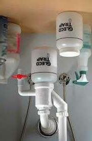
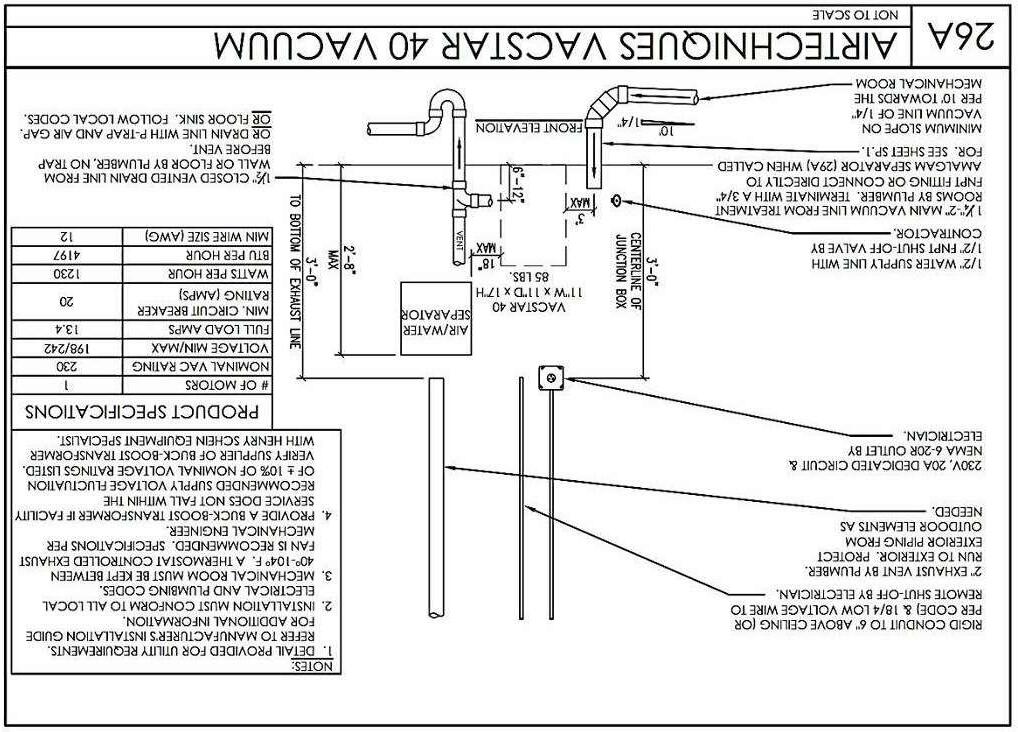
● Splash Shield ● Water Spray Attachment
Safety features include:
● Enclosed motor
● Special "trip-to-off" safety switch, shuts off motor if the door is opened during operation or in the event of a power failure. Waterproof on /off switch.
High-powered for high performance, the 3/4 HP Wet Model Trimmer will withstand years of rigorous use.
Unit measures, 15" W x 15-1/4" H x 13" D (38cm x 39 cm x 33 cm) Technical
HP Wet Model
Product Resources 3/4 HP Model Trimmer Operating Instructions Equipment Troubleshooting Guide 2008 Meeting Specials Buy any 12" Trimmer and get a Sediment Try Free Technical Support
3/4
Trimmer
3/4 HP wet trimmer operates at a full 1800 RPM
Specifications:
Voltage ○ 115V60 Hz
Amperage ○ 4A
●
●
Gleco Trap
No mor leaky bags or bulky buckets! Install the pre-assembled Gleco Trap once, the replacing the bottle takes less than one minute start to finish without tools. Simply turn side valve to drain off excess water, unscrew full bottle, and screw in a clean one. ● Side drain siphons out all water prior to removal, eliminating spillage. ● See-through bottle shows waste level. ● Adapts easily to existing plumbing ● The Gleco Trap is the only plaster trap to meet US Uniform Plumbing Code! System includes one trap assembly, two 64 oz. replacement bottles, all necessary 1/2" pipe components and simple instructions for a five-minute installation.
a) Medical Air Compressor shall comply with the NFPA 99 2015 Edition sec. 5.1.3. & 5.13.2. b) Medical Vacuum Pump shall comply with the NFPA 99 2015 Edition sec. 5.3.3.6 & 5.3.3.6.4. Specifications Part No. Max. Users Horsepower Panel Circuit Breaker Voltage (min/max) Pump Dimensions W x D H (in) Tank Included Tank Dimensions W x D H (in) Weights (lbs) V3 3 1.5 20A 198 242 25 x 21 x 17 MT10 29 x 22 x 33 Pump - 145 Tank - 75 V5 5 1.5 20A 198 242 25 x 21 x 17 MT10 29 x 22 x 33 Pump - 145 Tank - 75 V7 7 2.0 30A 198 242 25 x 24 x 17 MT10 29 x 22 x 33 Pump - 145 Tank - 75 2V3 6 3.0 20A (x2) 198 242 25 x 21 x 34 MT10 29 x 22 x 33 Pump - 145 (x2) Tank - 75 2V3CT 6 3.0 20A (x2) 198 242 25 x 21 x 34 CT20 29 x 22 x 33 Pump - 145 (x2) Tank - 75 Part Number Max. Users Pump Dimensions W x D x H (in) Weights (lbs) AS10 2 105 125 25 x 28.5 x 20 2.5 6 Voltage (min/max) CFM @ 80 PSI Tank Size (US gal) .75 AS12 2 200 250 25 x 28.5 x 20 2.5 6 .75 AS21 3 105 125 29 x 30.5 x 20 5.0 12 1.5 AS22 3 200 250 29 x 30.5 x 20 5.0 12 1.5 AS30 4 29 x 30.5 x 20 5.0 12 1.5 AS40 5 32.5 x 30.5 x 20 7.5 12 2.3 AS50 7 35.5 x 33.5 x 20.5 10.0 20 3.0 200 250 200 250 200 250 EXISTMAIN 1" C.W. 1" TO MODEL TRIMMER FINISHED FLOOR TRAP PRIMER HOSE BIBB 1/2" 48" A.F.F. WIRING AND SOLENOID FOR REMOTE SHUT - OFF CLEAR BODY HOUSE FILTER WITH SHUT-OFF AND BYPASS VALVES 1/2" B.P. EXPANSION TANK WATTS DET-5-MI WATTS VACUUM RELIEF DIELECTRIC FITTINGS & HEAT TRAPS 3/4" SUSPENDED PLATFORM 3/4" DRAIN TO FLOOR SINK, IN EQUIP.RM. 20 GAL. ELECT. (ABOVE CEILING) Efficiency: .93 EF for 30-gallon model Features: High Efficiency heating element Over-temperature protector cuts off power in excess temperature situations Automatic thermostat keeps water at desired temperature Wall bracket for easy wall mount installation and corrosion resistant 1/4 turn drain valve included with 2.5 gallon model Point-Of-Use electric water heaters feature a space- saving design for installation in limited spaces Plus Temperature and pressure relief valve Exclusive Rheemglas® tank lining resist corrosion and prolongs tank life Meets or excees National appliance Energy Conservation Act (NAECA) requirements These units are U.L.listed and comply with Underwriter's Laboratories Specification 174 Warranty: 6-Year limited tank and parts warranty.* *See Residential Warranty Certificate for complete information Units meet or exceed ANSI requirements and have been tested according to D.O.E. procedures. Units meet or exceed the energy efficiency requirements of NAECA, ASHRAE standar 90, ICC Code and all state energy efficiency performance criteria. The new degree of comfort.™ 6, 10, 15, 20 and 30-Gallon Point-of-Use 2.5, 6, 10, 15, 20 and 30-Gallon Capacities 120 Volt AC 2-Wire Single Phase Electric HOT WATER CONNECTION COLD WATER CONNECTION RELIEF VALVE CONNECTION WATER CONNECTIONS ALL 1/2" N.P.T. RELIEF VALVE CONNECTIONS 3/4" N.P.T. 2-1/2 GALLON MODEL A B ANODE ROD HOT WATER OUTLET C A B D COLD WATER INLET 6, 10, 15, 20 AND 30 GALLON MODEL C E SINK MODEL TRIMMER MODEL TRIMMER, VERIFY EXACT LOCATION WITH DENTIST WATER ANGLE STOP GLECO PLASTER TRAP B.P. 45 00 ° 1-1/2" MAIN TO VACUUM PUMP MANIFOLD CYLINDER ROOM N O O O ₂ CYLNDERS REGULATOR DISS HOSE MANIFOLD FIXED PIPING - 1/2" OD FOR O 3/8" OD FOR N ₂O OUTLET STATION(S) WALL ALARM OPERATORY AREA(S) DESK ALARM MONITORING AREA REGULATORS PRECISION ENGINEERED TO PROVIDE ACCURATE, DEPENDABLE SERVICE. LARGE 2", COLOR CODED GAUGES. OUTLET STATIONS AVAILABLE IN DISS AND QUICK CONNECT VERSIONS FOR EXPOSED OR CONCEALED PIPING - 02, N2O, VAC, N2, AIR - SINGLE, DOUBLE, AND TRIPLE GANG. HOSE ASSEMBLIES FURNISED AS REQUIRED. AVAILABLE IN DISS AND QUICK CONNECT STYLES FOR ALL MEDICAL GASSES-ANY LENGTH UP TO CODE LIMITS TYPICAL MANIFOLD SYSTEM SCHEMATIC INTAKE AIR PIPE A MINIMUM OF 10 FT FROM ANY DOOR, WINDOW EXHAUST OR OTHER INTAKE, OR OPENING IN THE BUILDING AND A MINIMUM OF 20 FT ABOVE GROUND SCREENED OPENING EXISTING ROOF 2" INTAKE AIR PIPE UP THRU ROOF AIR COMPRESSOR 2" EXHAUST AIR PIPE UP TRU ROOF VACUUM PUMP a) MEDICAL AIR COMPRESSOR SHALL COMPLY WITH THE NFPA 99 2015 EDITION SEC. 5.1.3. & 5.13.2. b) MEDICAL VACUUM PUMP SHALL COMPLY WITH THE NFPA 99 2015 EDITION SEC. 5.3.3.6 & 5.3.3.6.4. 10 FT MINIMUM NTS 1 WATER DETAIL NTS2 WATER HEATER DETAIL 2 NTS3 MODEL TRIMMER DETAIL 2 NTS4 VACUUM PIPE DETAIL 2 3/4" = 1'-0"5 Typical Manifold System Schematic NTS6 Mech Room Equipment Riser Checked By: Drawn By: Sheet Name/Number: Project Team: Issue Revisions: Plot Date: Project Name/Number: SCALE: © Copyright 2021 All information, drawn, written, or implied, appearing in this document constitutes the original and unpublished work of twenty20 Studio, LLC. and may not be duplicated, distributed, or disclose by any means without the prior written consent of twenty20 Studio, LLC. This is an instrument of services and sole property of the author. The use of this document shall be revoked any of the design intent or the construction methods shown herein are not adhered to, or the terms of the contractual agreement for its use violated. Written dimensions on these drawings shall have precedence over scale dimensions. Contractors shall be responsible for al dimensions and conditions on the job. twenty20 Studio, LLC must be notified of any variation from the dimension and conditions shown by these drawings. Contractor: MEP: A B C D E F G 1 2 3 4 5 6 7 8 9 10 1 2 3 4 5 6 7 8 9 10 Designer: twenty20Studio, LLC Contact: Ramon Gisbert t: 346.388.3820 formerly RJG Design Studio, LLC 5815 Gulf Fwy Houston, TX 77023 Sheet Size: 24" x 36" RJG SA. Aftab Ur Rahman 21027 ARCHITECTURE + PLANNING studio TAS TDLR Otten Consulting Group Contact: Kathy Rodriguez t: 713.975.1029 Solution Engineering Contact: Duwan Cotton, PE t: 713.376.9801 Custom Practices Contact: Trevor Fawcett t: 713.836.2811 Safari Family Dental PERMIT 9/22/2022 As indicated 14/11/2022 4:10:56 pm PLUMBING DETAILS P1.5
