ANNE ELIZABETH BLACKBURN IS A THIRD YEAR MASTER OF ARCHITECTURE STUDENT AT THE UNIVERSITY OF VIRGINIA. SHE RECEIVED HER BACHELOR OF SCIENCE IN GEODESIGN FROM THE UNIVERSITY OF SOUTHERN CALIFORNIA. SHE HAS WORKED AT ARCHITECTURE FIRMS IN NASHVILLE, TN AND NEW YORK CITY, MOST RECENTLY IN HIGH END RESIDENTIAL. THE FOLLOWING IS A SELECTION OF HER ACADEMIC AND PROFESSIONAL WORK.
ACADEMIC WORK
SHORELINE STATION
PROJECT TYPE: RESEARCH FIELD STATION
LOCATION: SAXIS ISLAND, EASTERN SHORE, VA
SPRING 2025 FOUNDATION STUDIO 4
PROFESSOR JEANA RIPPLE AND MARTA JARABO
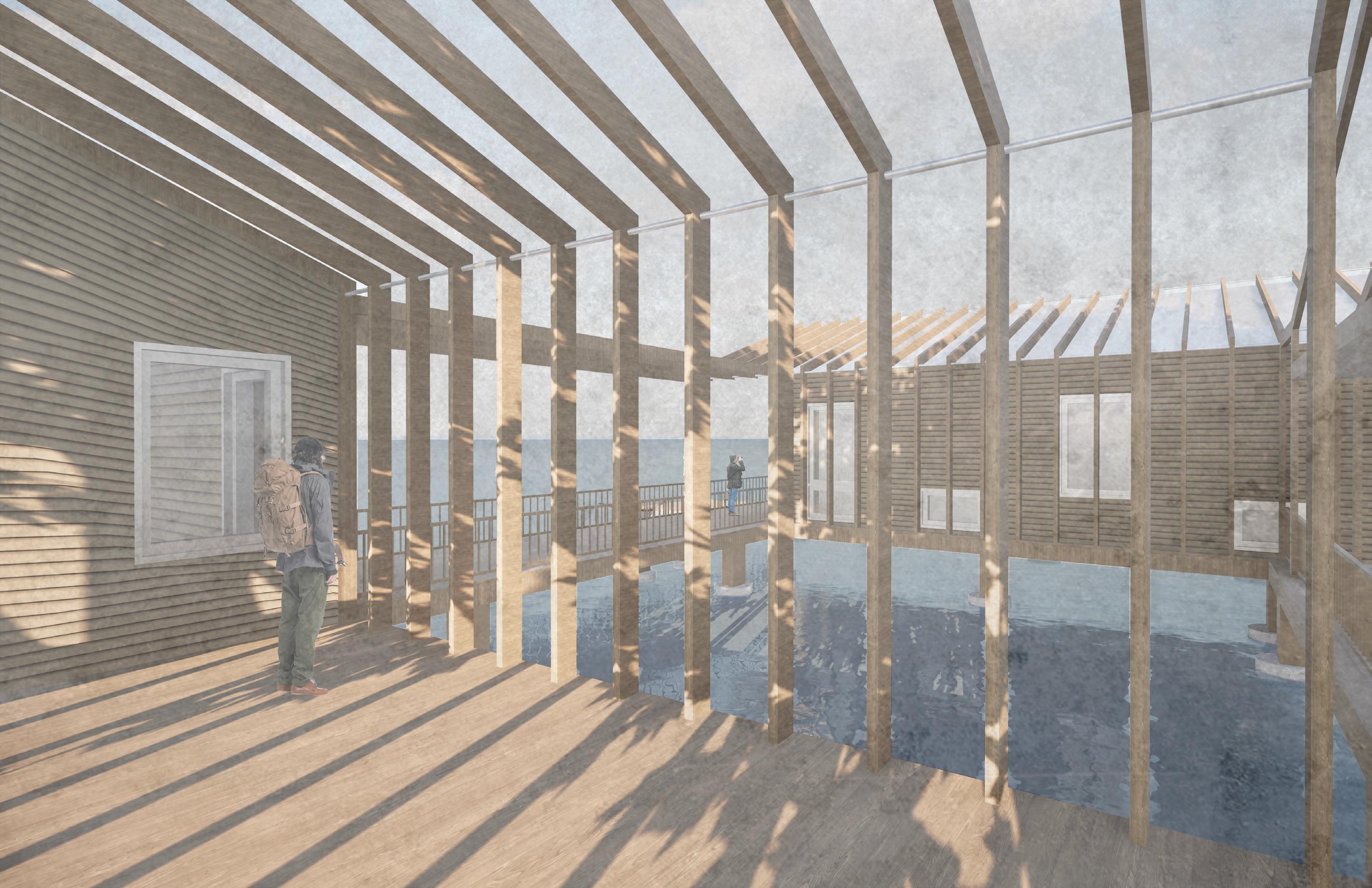
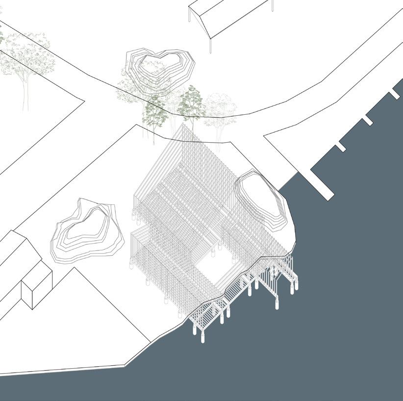
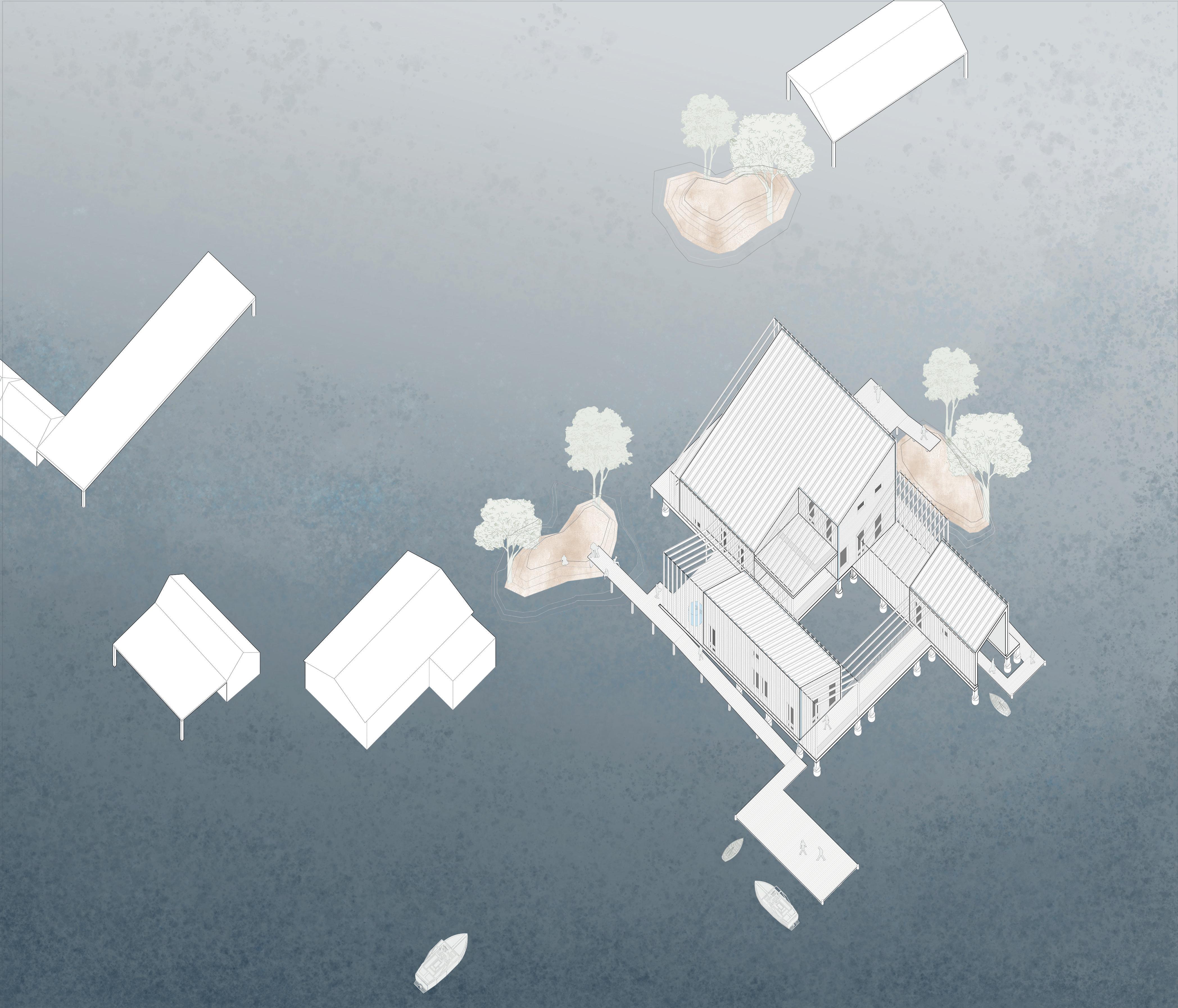
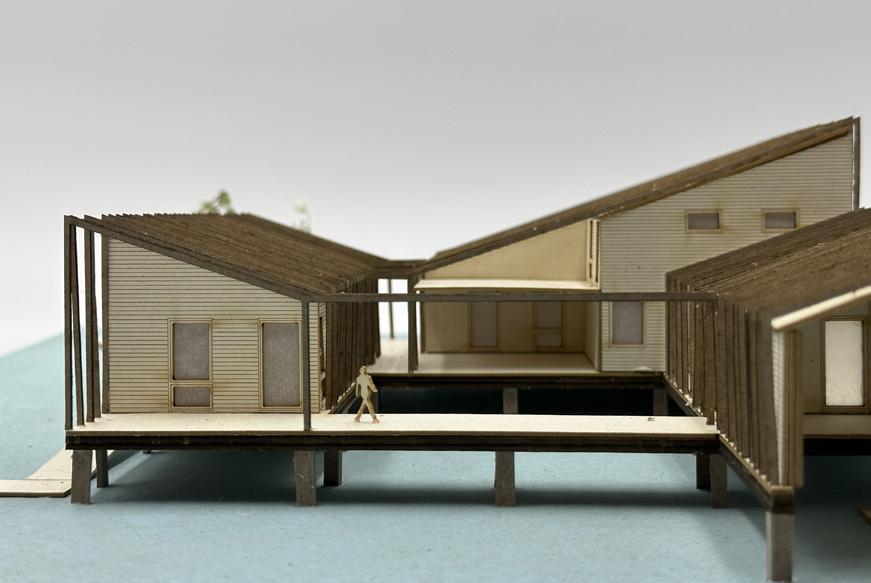
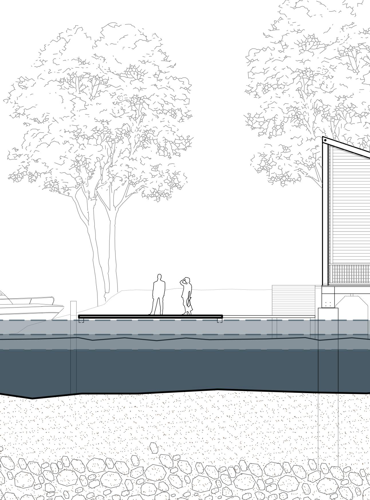
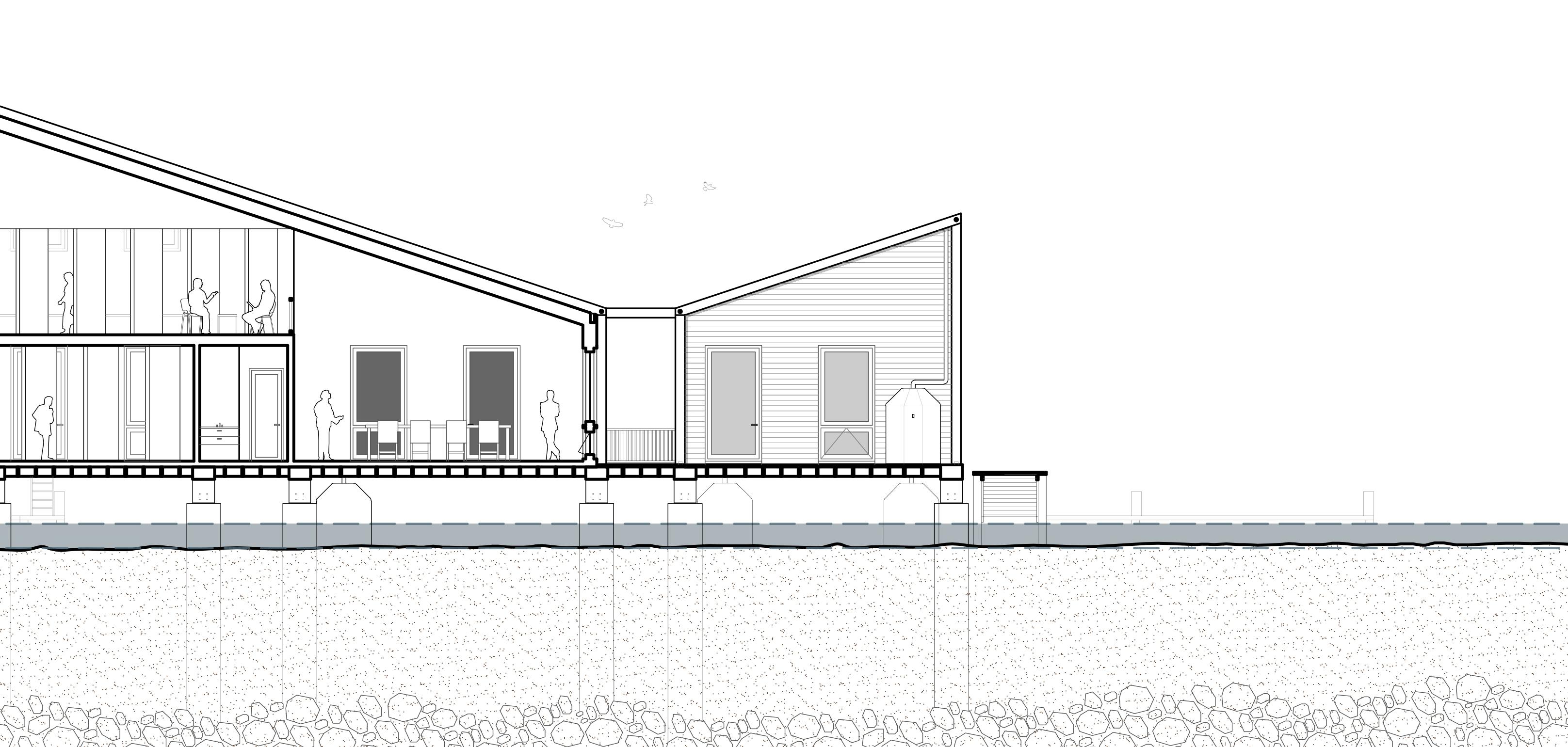
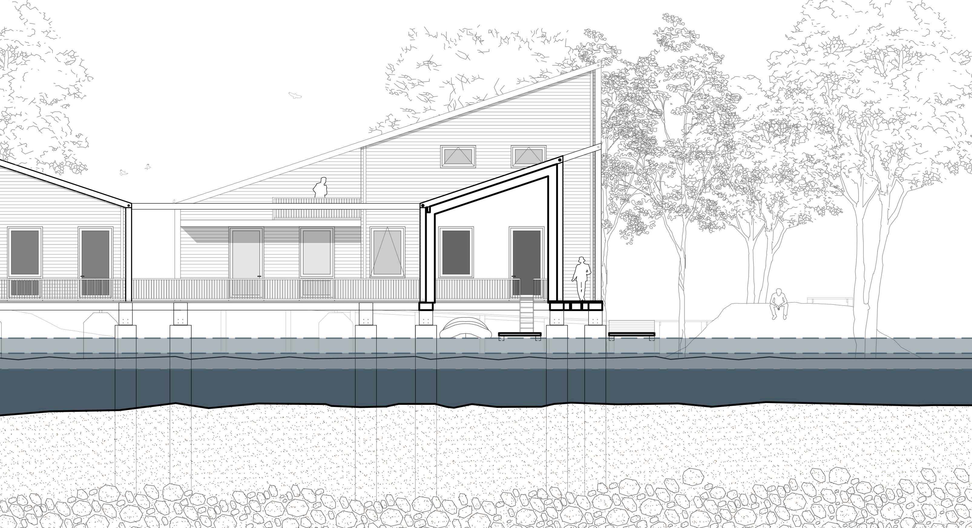
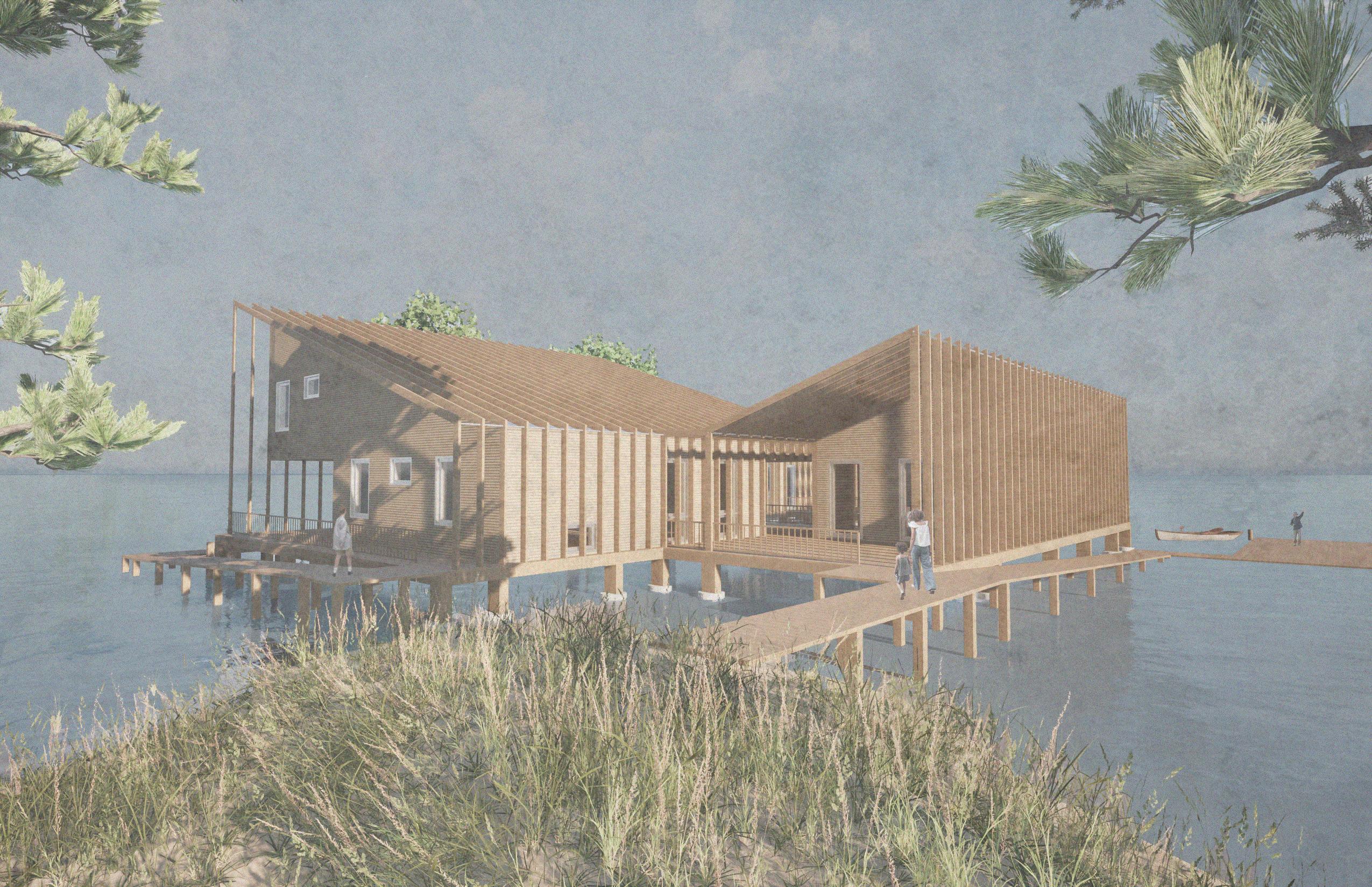
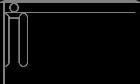
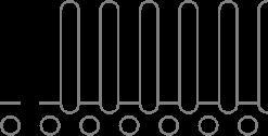
The Saxis Island Field Station embraces water as both adversary and ally - recognizing it as a force to defend against, a resource to harvest, and a medium for connection. Elevated on concrete piers, the structure anticipates the rising Chesapeake Bay, adapting through modular growth inspired by the Eastern Shore typology of “Big House, Little House, Colonnade, Kitchen.” Beginning as a simple wooden frame and platform, the building evolves over time, adding new infilled volumes in response to changing sea levels and needs. Its flexible, bolted-together system enables both rapid assembly and graceful disassembly when inundation becomes inevitable, demonstrating resilience in the face of uncertainty.
Yet, water is also treated as an asset. Sloped roofs capture up to 31,600 gallons of annual rainfall per 1,000 square feet, channeling it into filtered tanks beneath the structure. This decentralized system provides free, potable water for residents and researchers alike, redefining access and equity on an island where clean water has long been privatized.
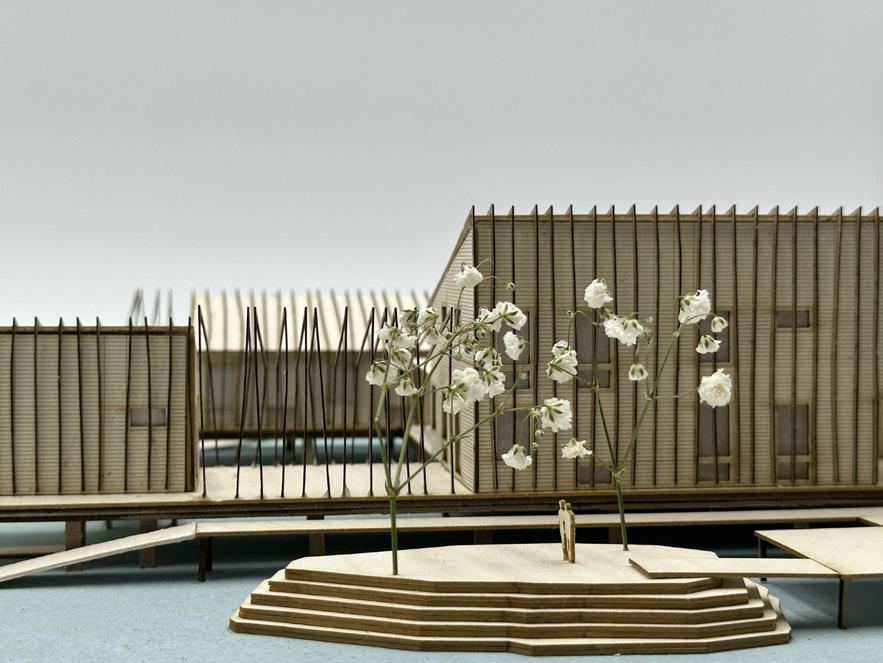
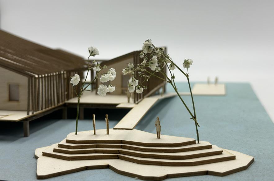
Finally, water becomes community. Public faucets, floating docks, and elevated catwalks link the building to raised green mounds, transforming water access into civic space. Here, people gather, rest, and reflect - reframing the rising tide as an opportunity for collective resilience rather than retreat.
Exterior Render
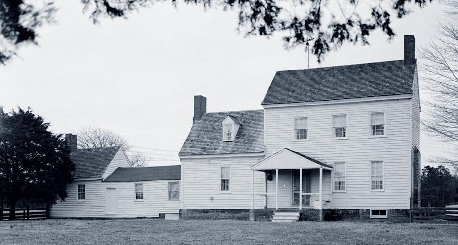
It is essential for the building to be able to transform in response to changing sea levels and adapt to new needs that will emerge as the Chesapeake Bay’s climate changes. This concept of incremental growth - driven by necessity - draws inspiration from the Eastern Shore housing typology known as “Big House, Little House, Colonnade, Kitchen”, a unique housing typology around the Eastern Shore of Virginia. This historic type of home was not built all at once, but was constructed over time. The first section was usually a 2 story small home with a dormer roof. As the owner became wealthier or their family grew, a 1.5 story addition was added. The kitchen was detached from the house as a fire prevention method, but, when cooking became less dangerous, the colonnade was added to connect the kitchen with the rest of the house.
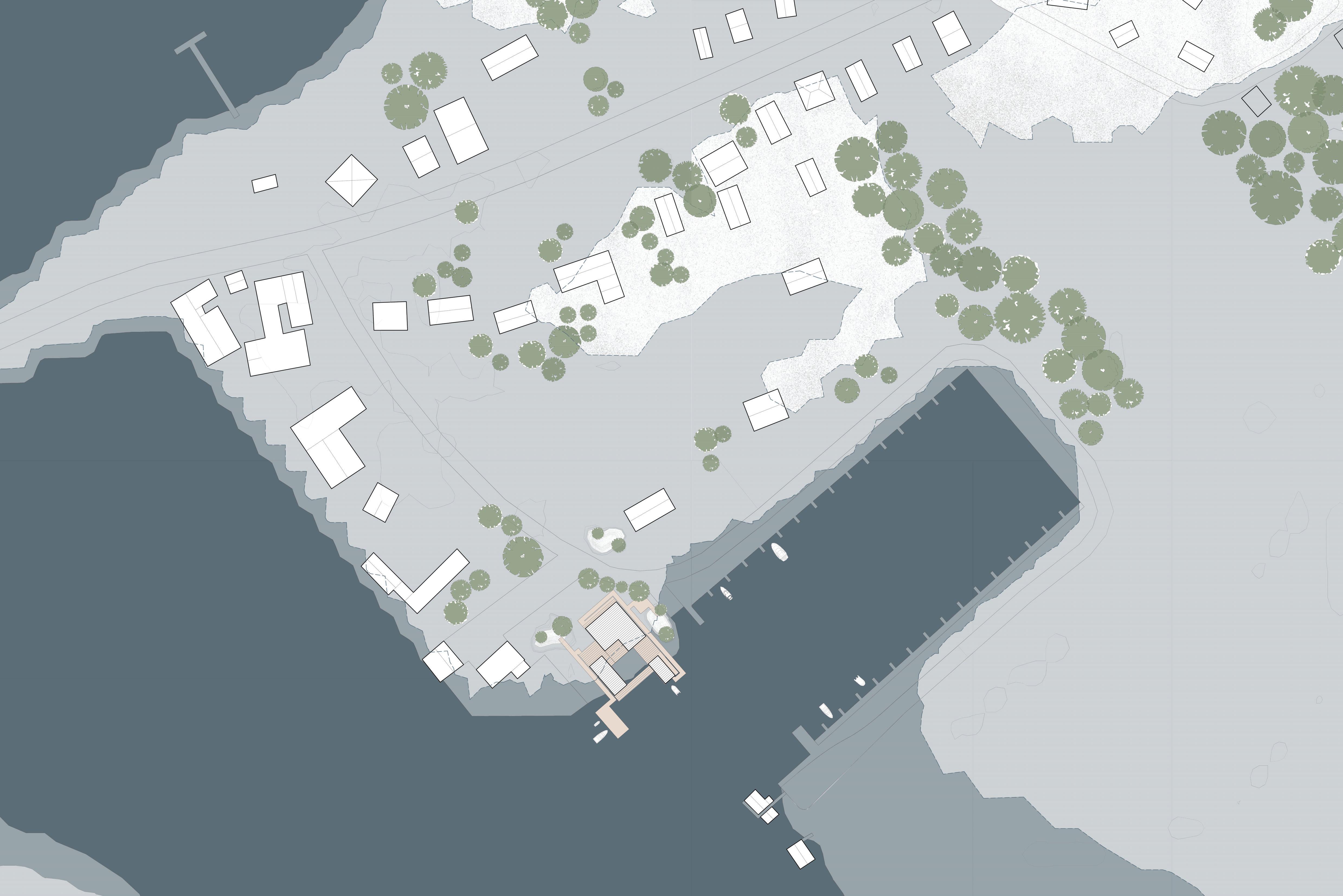
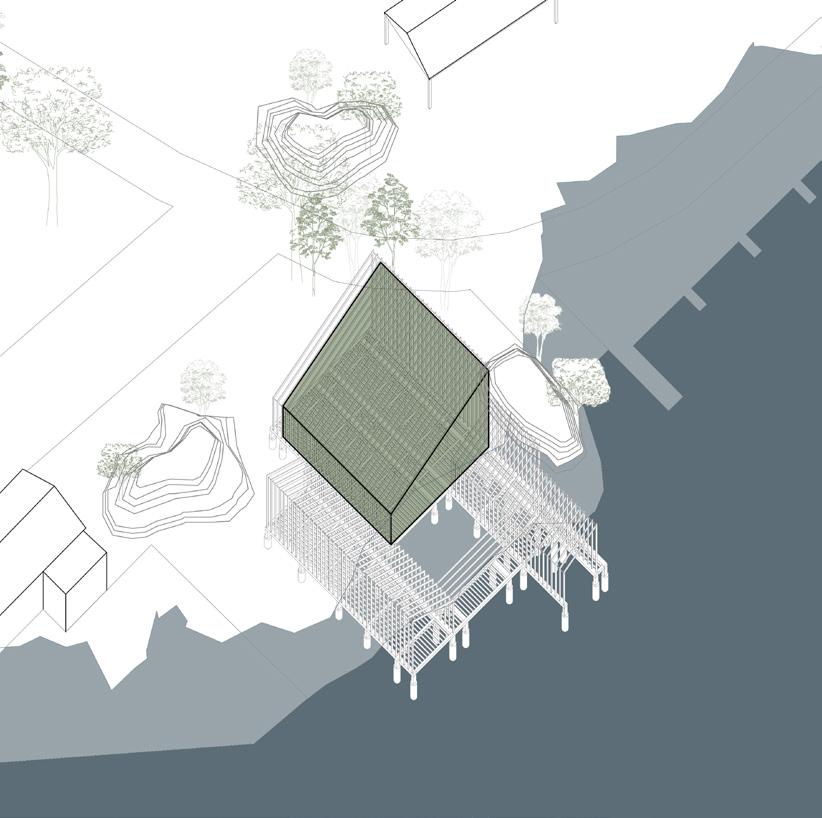
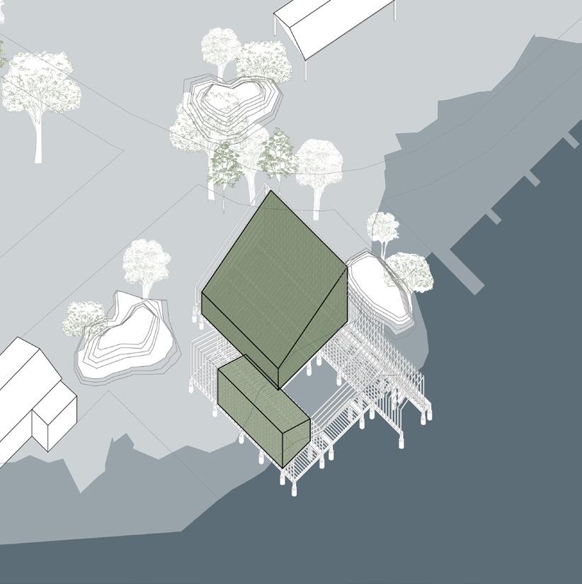
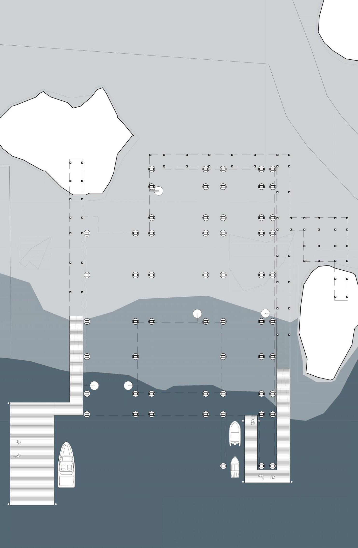
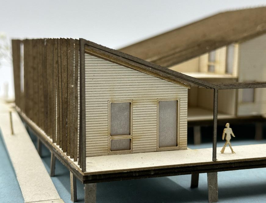
The transformation occurring in the proposed design is made possible by the building’s structural strategy. Initially, the building begins as just an empty wood frame that is purposefully left empty, acknowledging the unpredictable demands of the next 100 years. Over time, the frame is infilled with panels that are fabricated off-site, then brought to the site and attached to the wood exoskeleton using bolts and screws. Breaking the building into modular components simplifies transportation and assembly during uncertain and stressful times, while also allowing for an easier eventual disassembly when Saxis Island becomes fully inundated. The frame is infilled to create a research center, researcher lodging, and boat house. The boathouse arises from the need to access the field station from the base station via boat, because the main road will be fully inundated. The field station is located along the shore of an existing marina, located in a spot that it intentionally engages with the rising sea levels.
Runnymead, Accomack, VA
2100, 4 Foot Rise
Boat Level Plan, 0 Feet Above Sea Level Year 2100
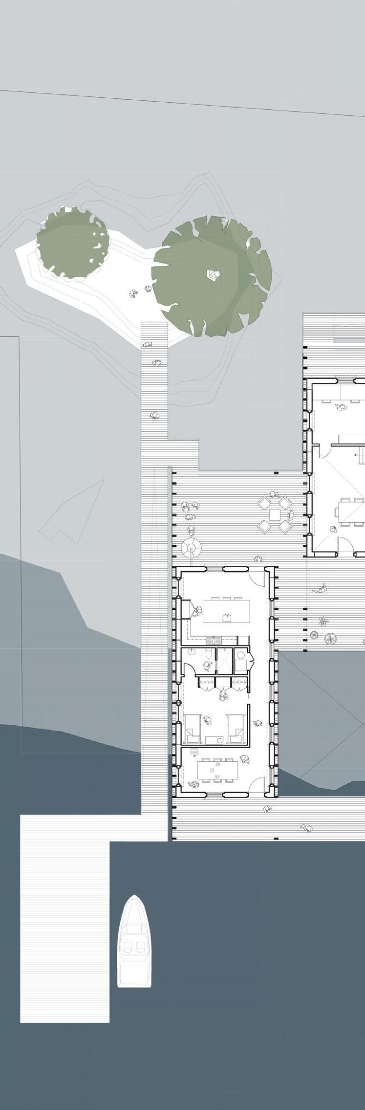
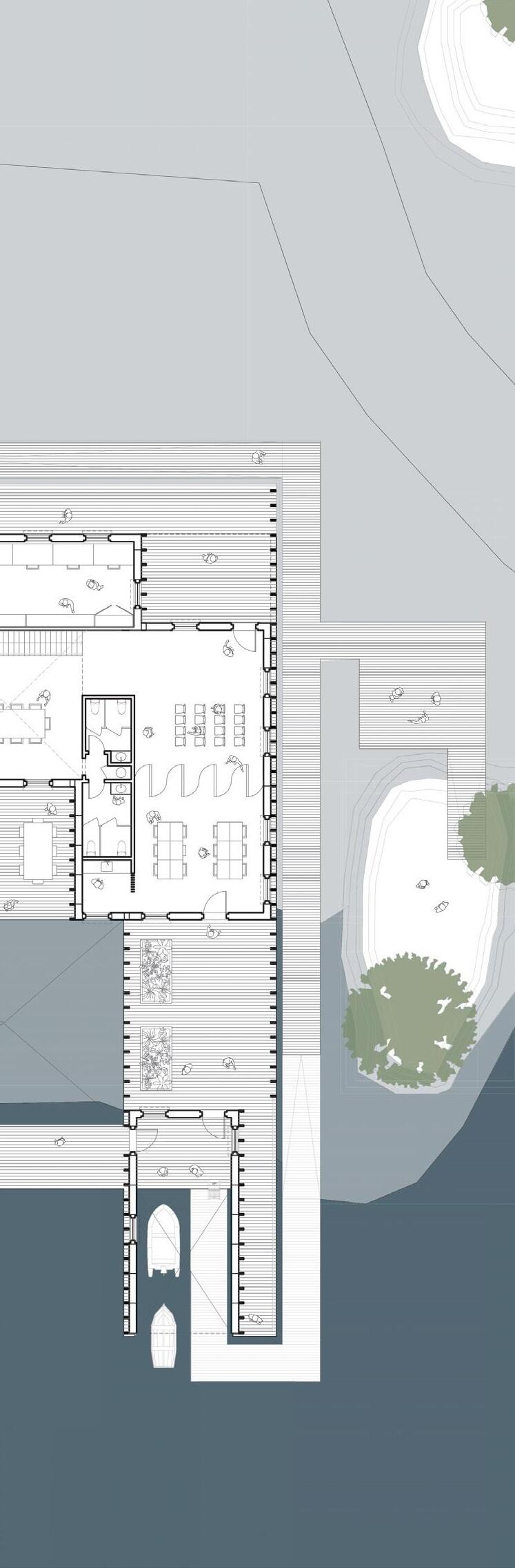
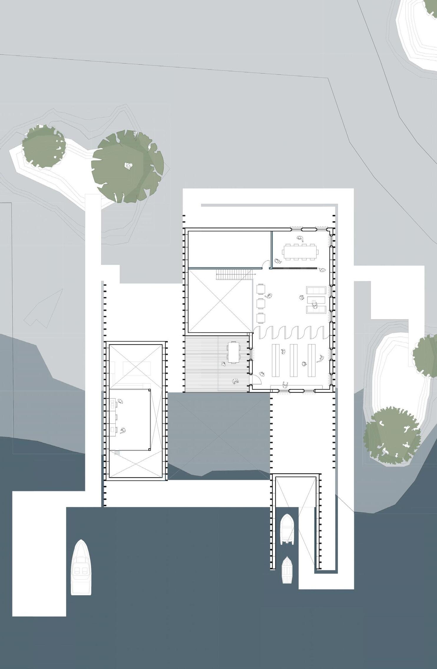
First Floor Plan, +5 Feet Year 2100
3”x9” Timber Frame, 2’-4” Spacing, Connected with Steel Cable, Secured to Base Frame with Steel Plate
Prefabricated Panel Components, Green Oak Wood Exterior Finish, Attached to Timber Frame with Screws
Timber Floor Framing, 2x10 Floor Joists with 16” Spacing
Concrete Pillar Foundation with Timber Post
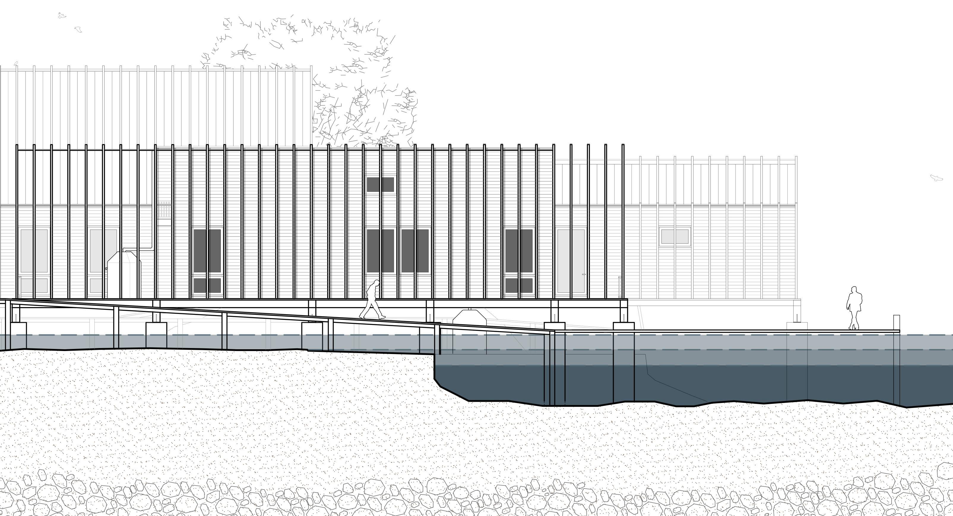
North Elevation Year 2100
West Elevation Year 2100
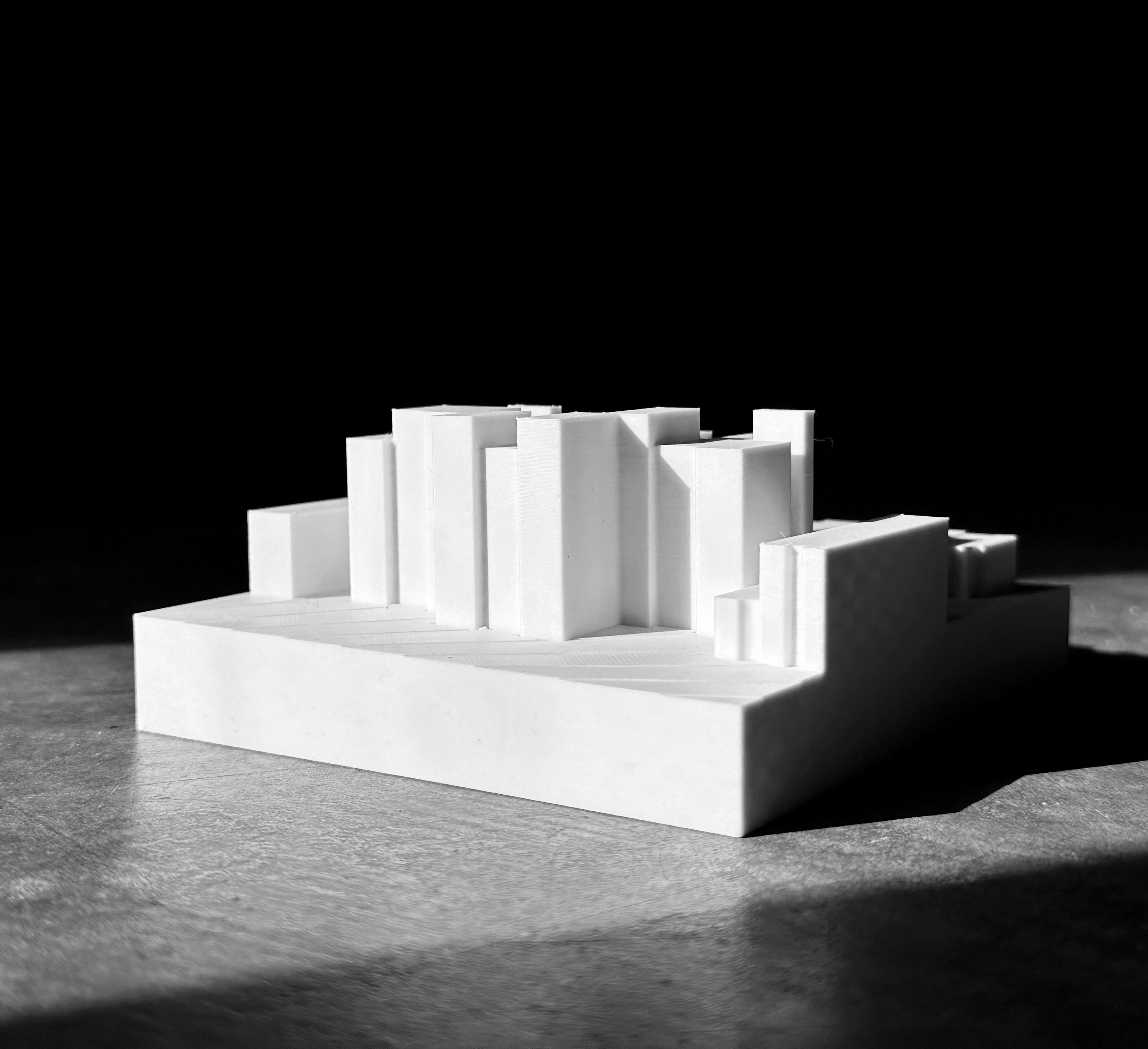
Model Photos
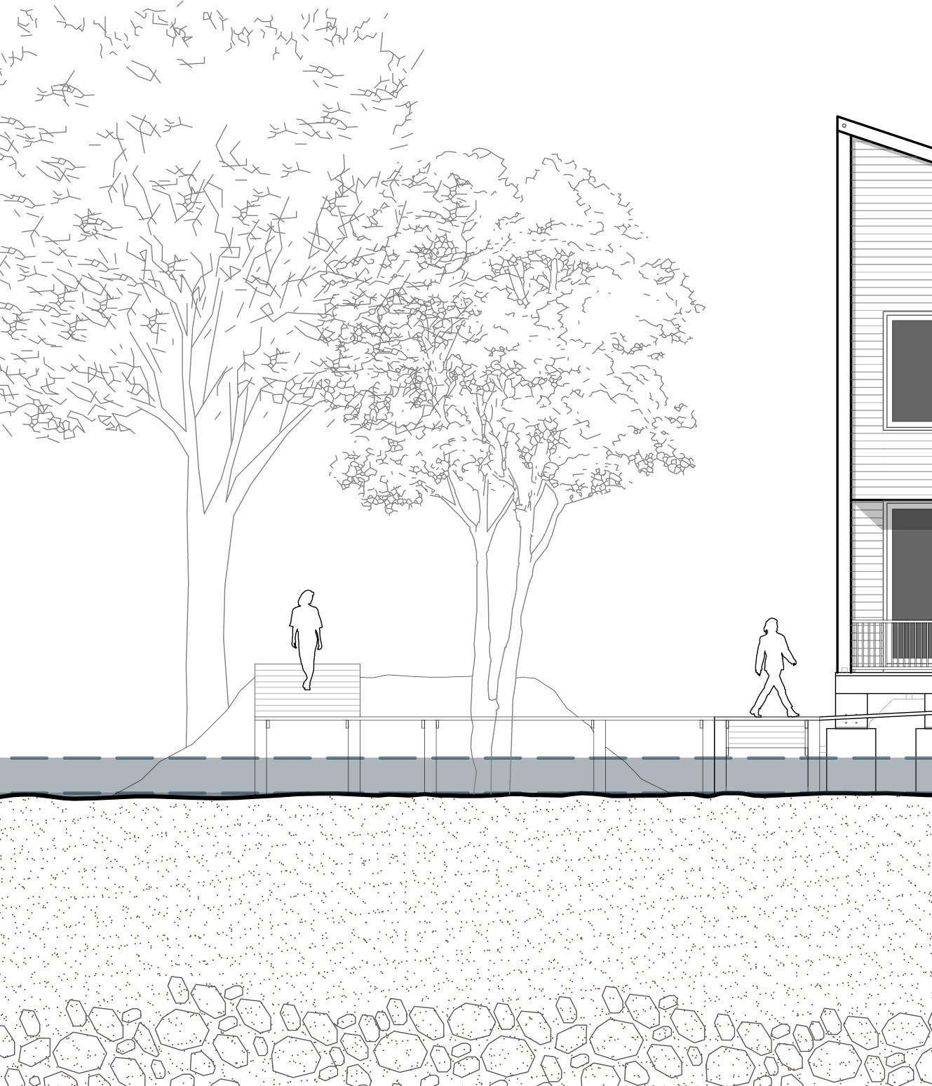
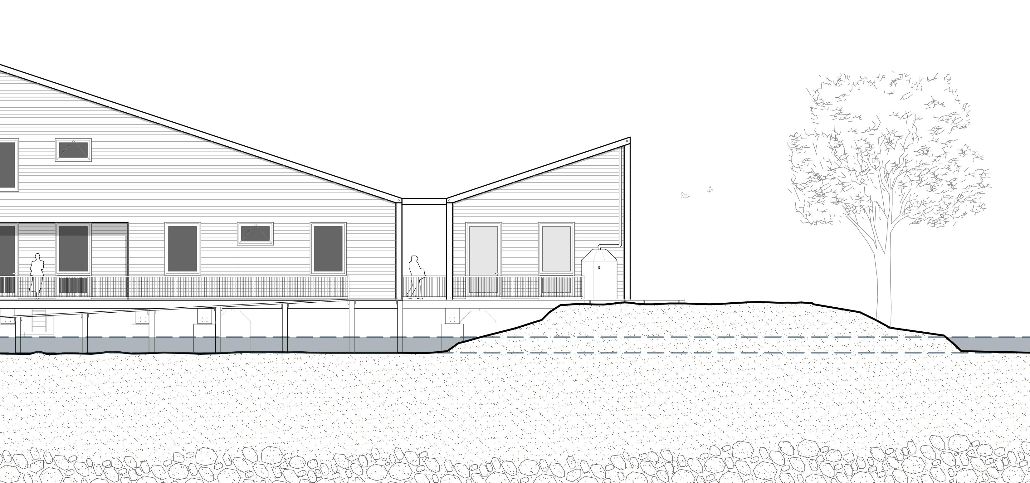
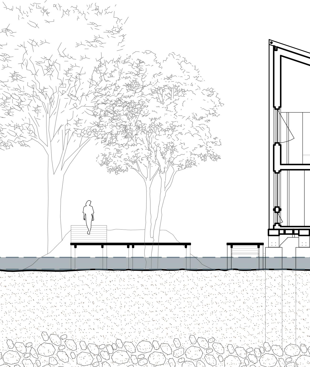
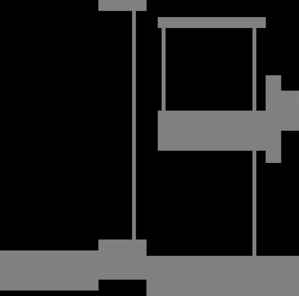
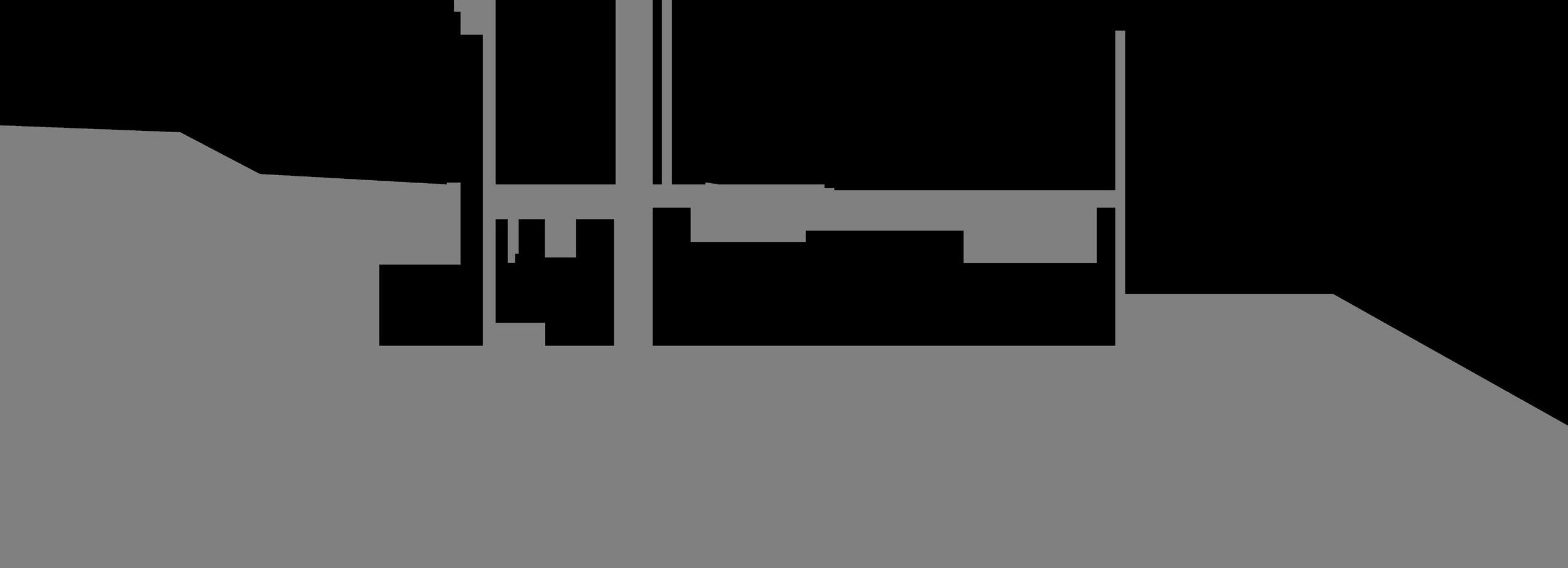
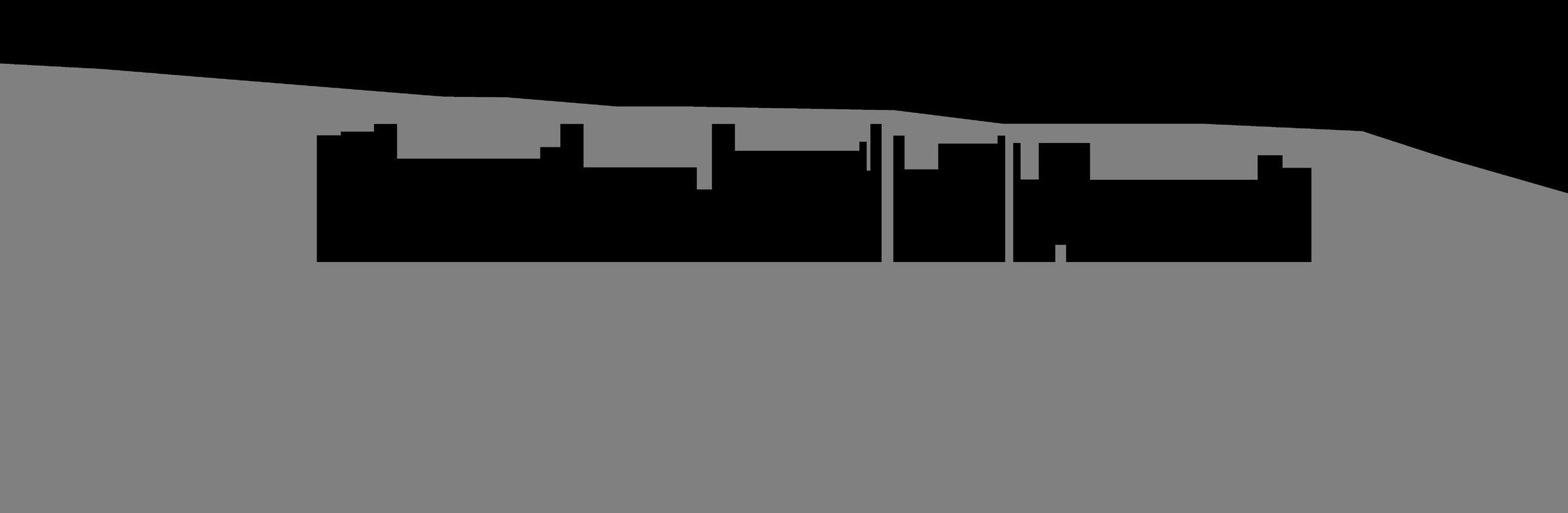
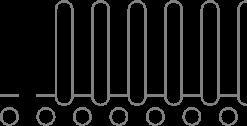
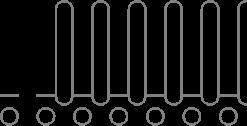
Section Year 2100
Section Year 2100
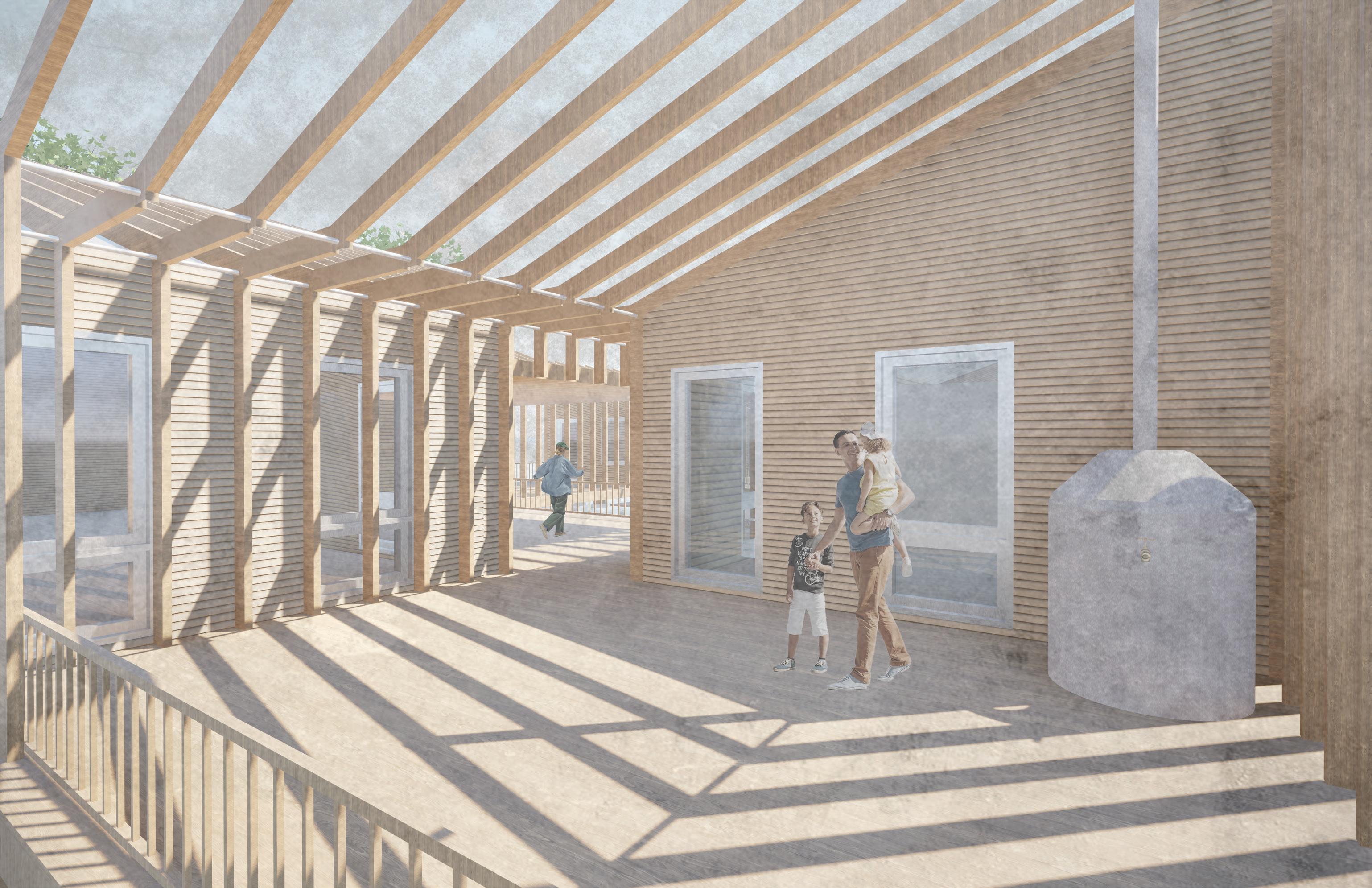
Community Space and Water Collection Render
Building Elevated on Pillars
Elevated Path to Access Building
Mounds to Provide New Green Space
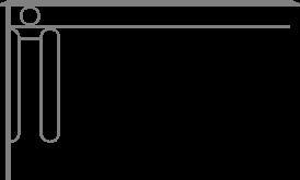
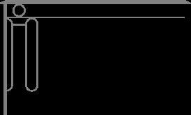
The building is elevated off the current sea level by 9 feet on concrete pillars to protect the wooden elements, providing ample protection over the next 100 years. Access to the building level ascends from the boat docks, now the primary point of entry. The boat docks are floating, allowing them to rise with the changing sea levels, and are attached to fixed catwalks that lead to the building or the mounds. On Saxis Island, VA, all potable water is currently privately operated and owned. This proposed design challenges that idea by offering free, publicly accessible potable water to both the island’s residents and visiting researchers. On average, Saxis Island receives 47 inches of rainfall annually, which can result in collecting up to 31,600 gallons of water per 1,000 square feet of roof. Rainwater flows across the sloped roofs to the hidden gutters and travels through them to water tanks located below the building or on the exterior decks in communal spaces that the public can easily access. The collected water is filtered for use in drinking, irrigation, and sanitary systems, creating a decentralized and resilient water infrastructure that supports both environmental sustainability and social equity. To reduce reliance on active building systems, the structure forgoes air conditioning, instead relying on passive natural ventilation enabled by its angled form and operable windows. Heating is integrated into the elevated flooring system constructed atop the initial floor framing.
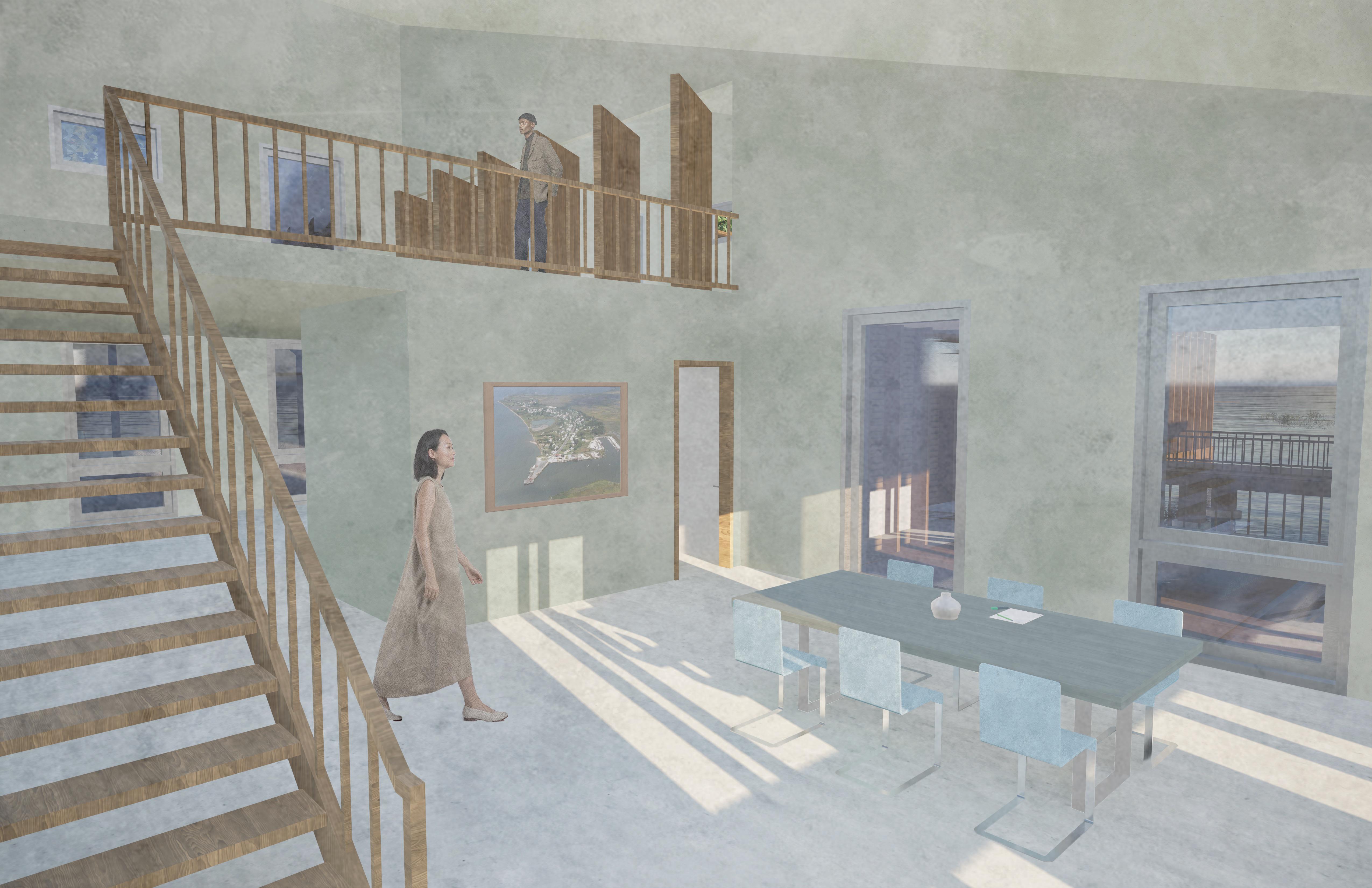
Potable water tanks with accessible faucets are intentionally integrated into the building’s communal spaces, transforming the act of accessing water into a social and civic experience. These gathering points emphasize water as a shared resource and invite community interaction around a basic human need. Across the site, landscaped mounds are raised to create shaded green spaces beneath the sparse canopy of remaining trees. The idea of the mound comes from existing practices in Saxis of dredging to maintain boat access, and excess soil and sand from this practice will be used to create the mounds. Looking to the future, this landscape strategy can be replicated to form a network of small artificial islands linked by additional catwalks and floating docks. These spaces are designed for rest, swimming, gathering, or reflection - offering new ways to engage with the Chesapeake Bay. This approach seeks to reframe water not solely as a threat due to sea-level rise, but as a potential catalyst for connection, resilience, and community.
Research Center
Research Center
Research Center
Researcher Lodging
Research Center and Community Meeting Space
Researcher Lodging
Boat House
Research Center and Community Meeting Space
Emergency Temporary Lodging for Displaced People
Boat House
ROW-HOUSE RE-IMAGINED
PROJECT TYPE: COMMUNAL HOUSING
LOCATION: WASHINGTON D.C.
FALL 2024 FOUNDATION STUDIO 3
PROFESSOR PETER STEC
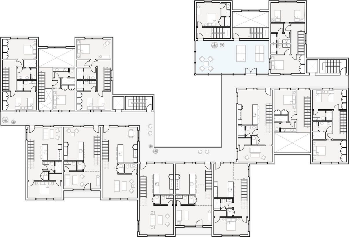
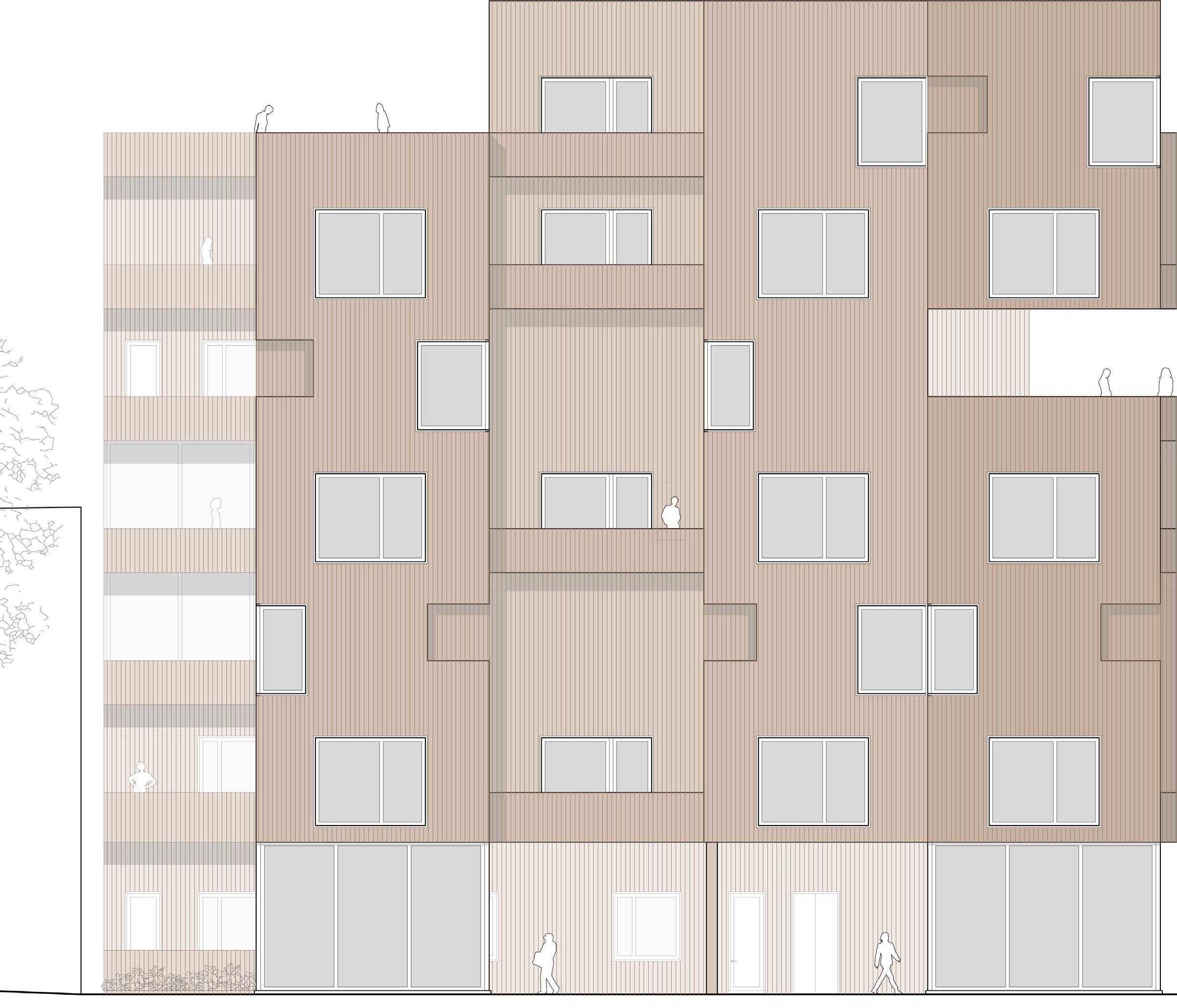
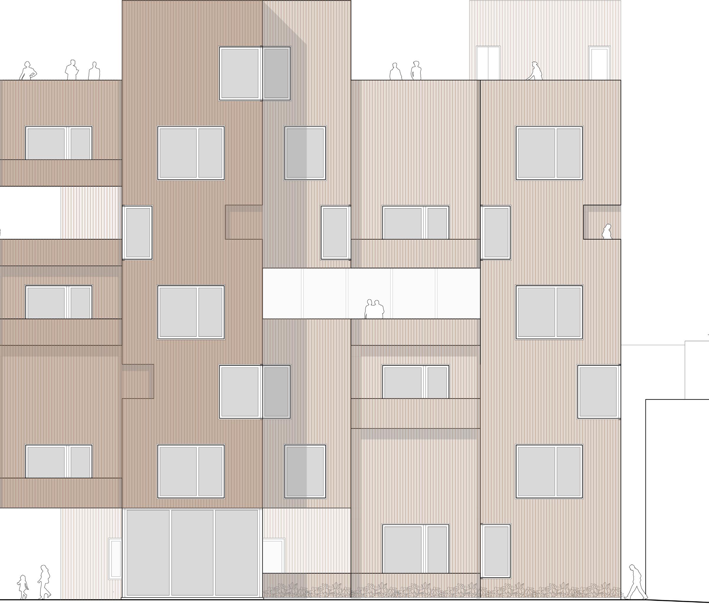
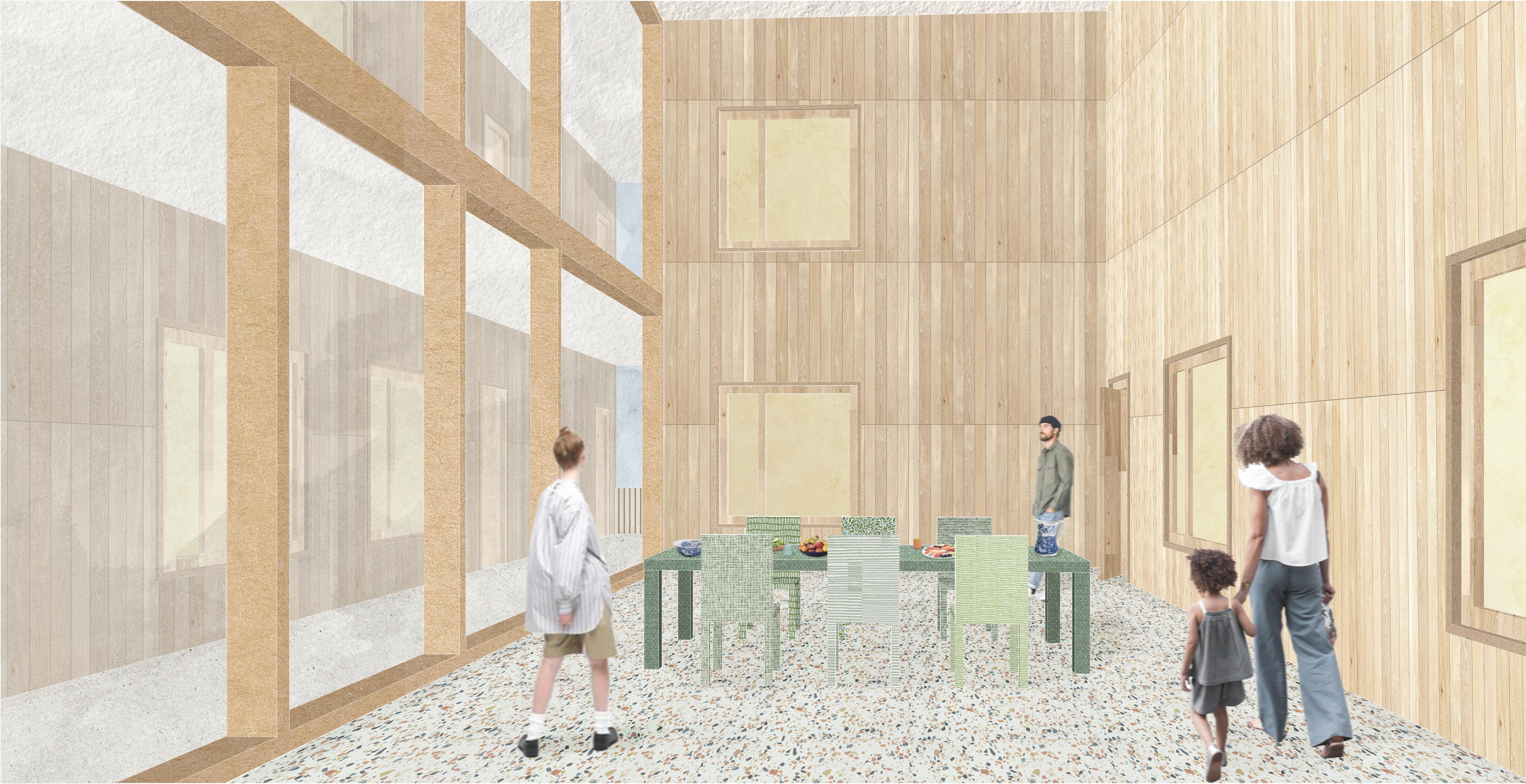
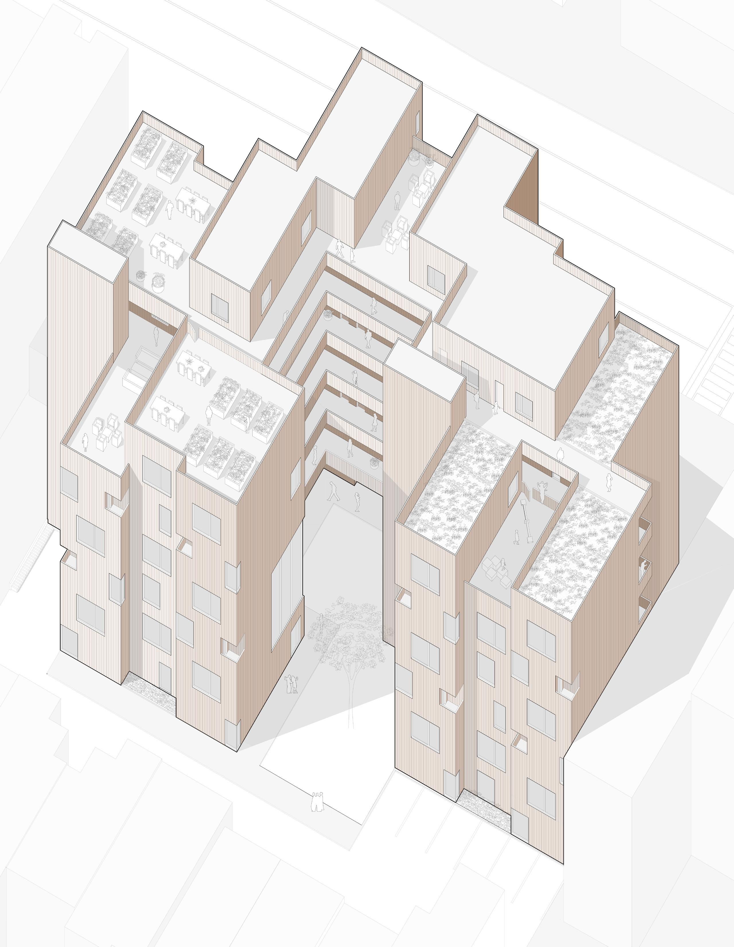
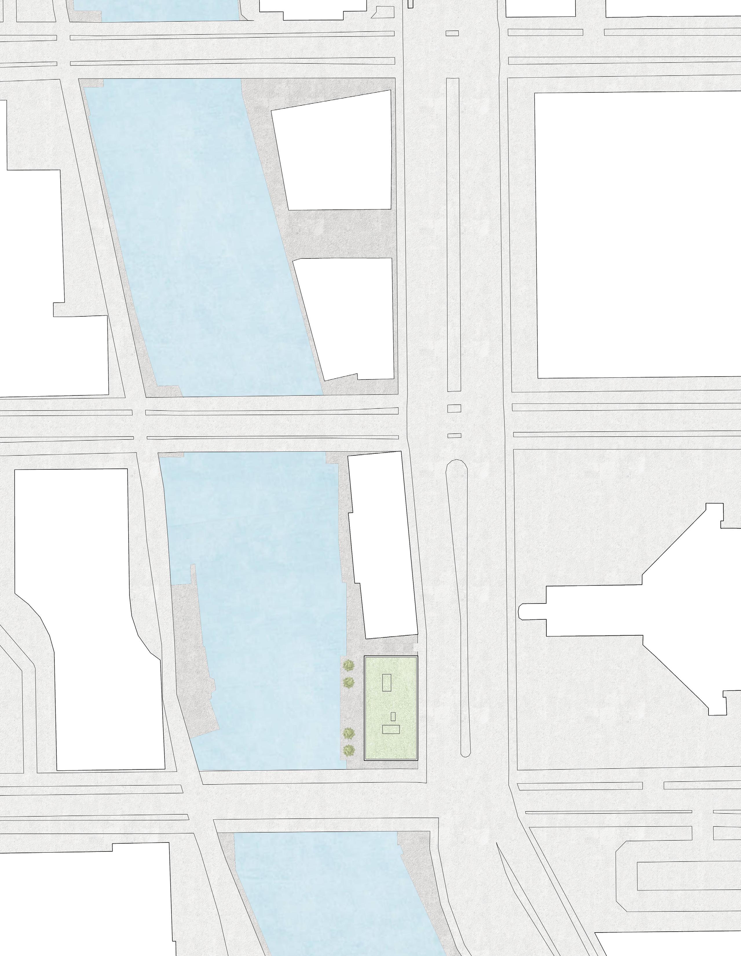
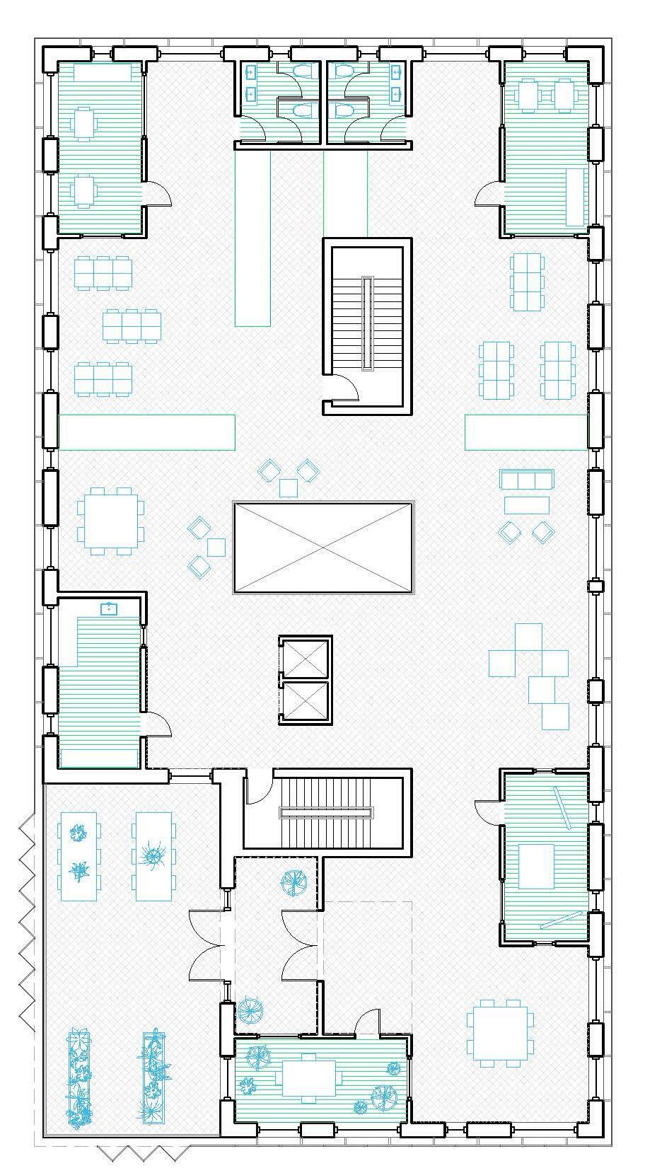
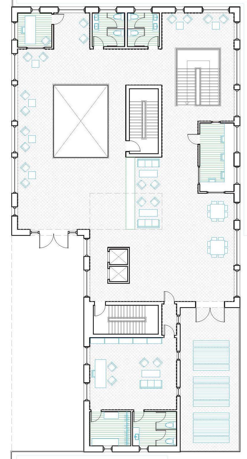
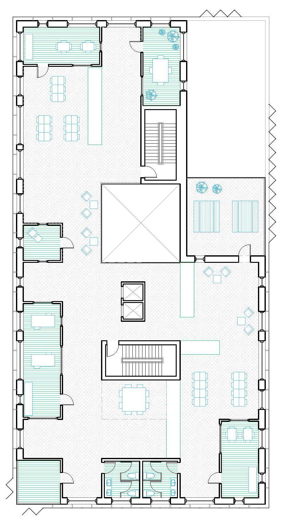
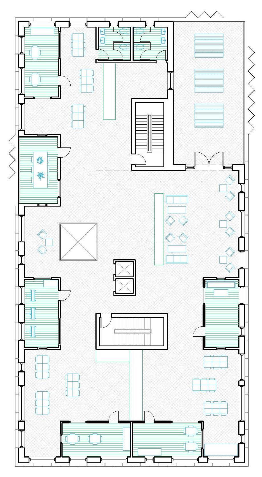
This design proposes an 82,000-square-foot, seven-story communal housing project in Washington, D.C.. The primary inspiration for the building footprint is the row house, an emblem of D.C. residential architecture. The project is located in Woodley Park, a neighborhood characterized by mid to low-rise residential buildings. It was important for the proposed design to maintain the scale of residential living through a familiar icon, like the row house, but in a more efficient way of living.
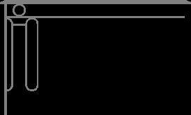
The footprint of each unit comes directly from the size of the surrounding row homes, which are 20 feet by 40 feet or 20 by 45 feet, and all units are two to three stories tall. The building mass comes from a stacking and clustering of row houses, which allows for denser dwellings while opening up the ground floor. There are five clusters of 3 units, each connected by exterior paths. The purpose of using exterior circulation between the units is to maintain the idea of a front stoop of a row house and a semi-public, semi-private entrance as you enter the unit. The units are clustered around a central courtyard. Communal spaces are located throughout the building and feature a co-working space, communal dining room, communal gardens, children’s play area, a library, and resident lounges.
Proposed Design Massing Model
DISTANCE
FROM METRO STOPS
The rail system has 40 stations in the D.C. area. Along Connecticut Avenue, there are five metro rail stops with one in Woodley Park and one in Cleaveland Park.
Closest to Metro Station Farthest from Metro Station
The set of maps analyze connectivity across D.C. and Woodley Park, where the proposed housing design is located. The connective networks explored in this urban analysis are the Metrorail and Metrobus routes, roads, bike lanes, and walking. The site is situated along Connecticut Avenue, a highly trafficked road that connects Downtown D.C. to Maryland, and the Metrorail Red Line. While Woodley Park is well equipped in public transportation, it is lacking in walkability. The proposed design seeks to improve this issue through opening up the site to pedestrians to allow access to the road and row houses in the rear of the building.
METRO LINES AND STOPS
The Metro consists of six color-coded lines: Red, Blue, Orange, Yellow, Green and Silver. The red line runs along Connecticut Avenue in Woodley Park and Cleavland Park. In 2023, the number of passengers transported on the Washington, D.C. transit authority network amounted to approximately 231 million. There is a 0.5 mile buffer around each metro stop which is typically the distance people are willing to walk somewhere.
BUS LINES
The metrobus is D.C.’s regional bus service and is the sixth busiest bus agency in the United States.
Metrobus has a fleet of more than 1,500 buses operating on approximately 325 routes.
Better Bus is Metro’s overarching initiative to improve Metrobus for the region. In the coming years, there will be new facilities, zero-emissions vehicles, improved bus communications, and more bus lanes and transit signals.
BIKE LANES
D.C. currently has over 95 miles of bike lanes, with intentions to expand the city’s biking network over the next three years. As of 2018, 4.5% of commuters biked to work.There are currently no bike lanes in the Woodley Park or Cleaveland Park area.
ROADS
D.C.’s streets are organized in a scheme of broad diagonal avenues overlain on a grid of wide northsouth- and east-west-trending streets. Thus, an orderly web of wide tree-lined avenues creates great vistas and leads both to powerful focal points and open public spaces. The intersections of two or three diagonal avenues are punctuated with landscaped circles and squares, while their intersections with grid streets create triangular and trapezoidal lots and parks.
FRIENDLINESS INDEX
PEDESTRIAN
A Pedestrian Friendliness Index (PFI) analysis characterizes the walkability of an area based on sidewalk availability, building accessibility, and street network design. An area deemed ‘most walkable’ has a connected street grid with sidewalks, buildings set close to the street, and intersections and blocks that are manageable for pedestrians.
Diagram
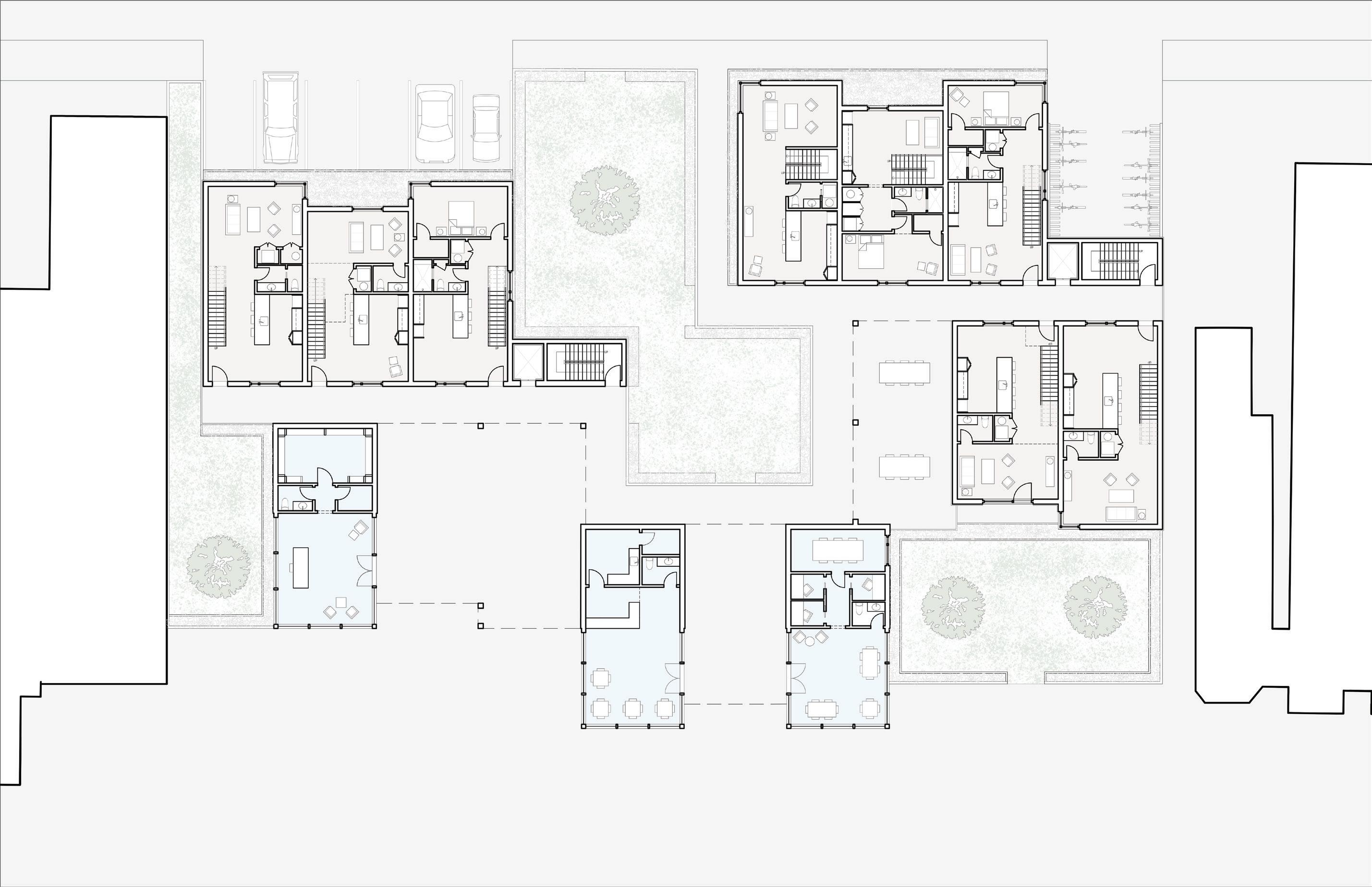
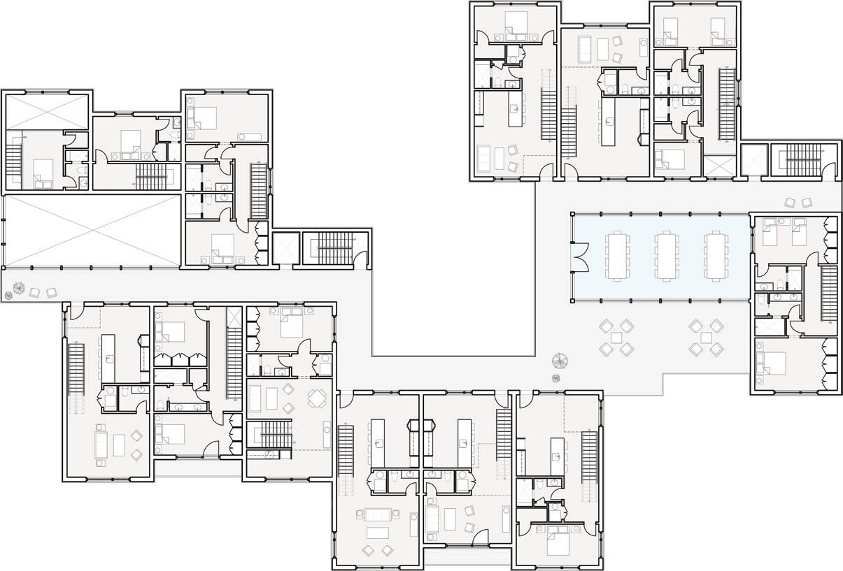
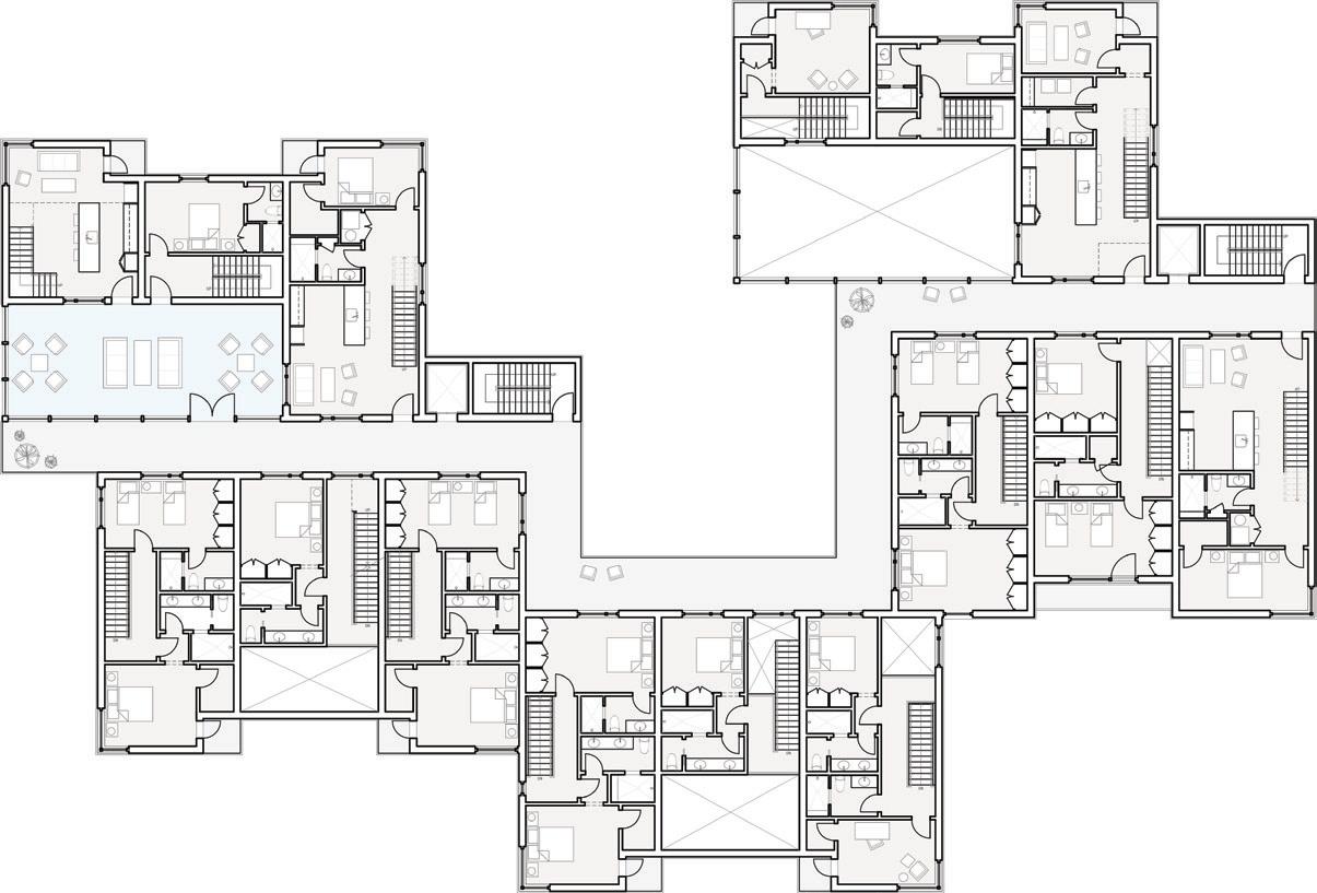
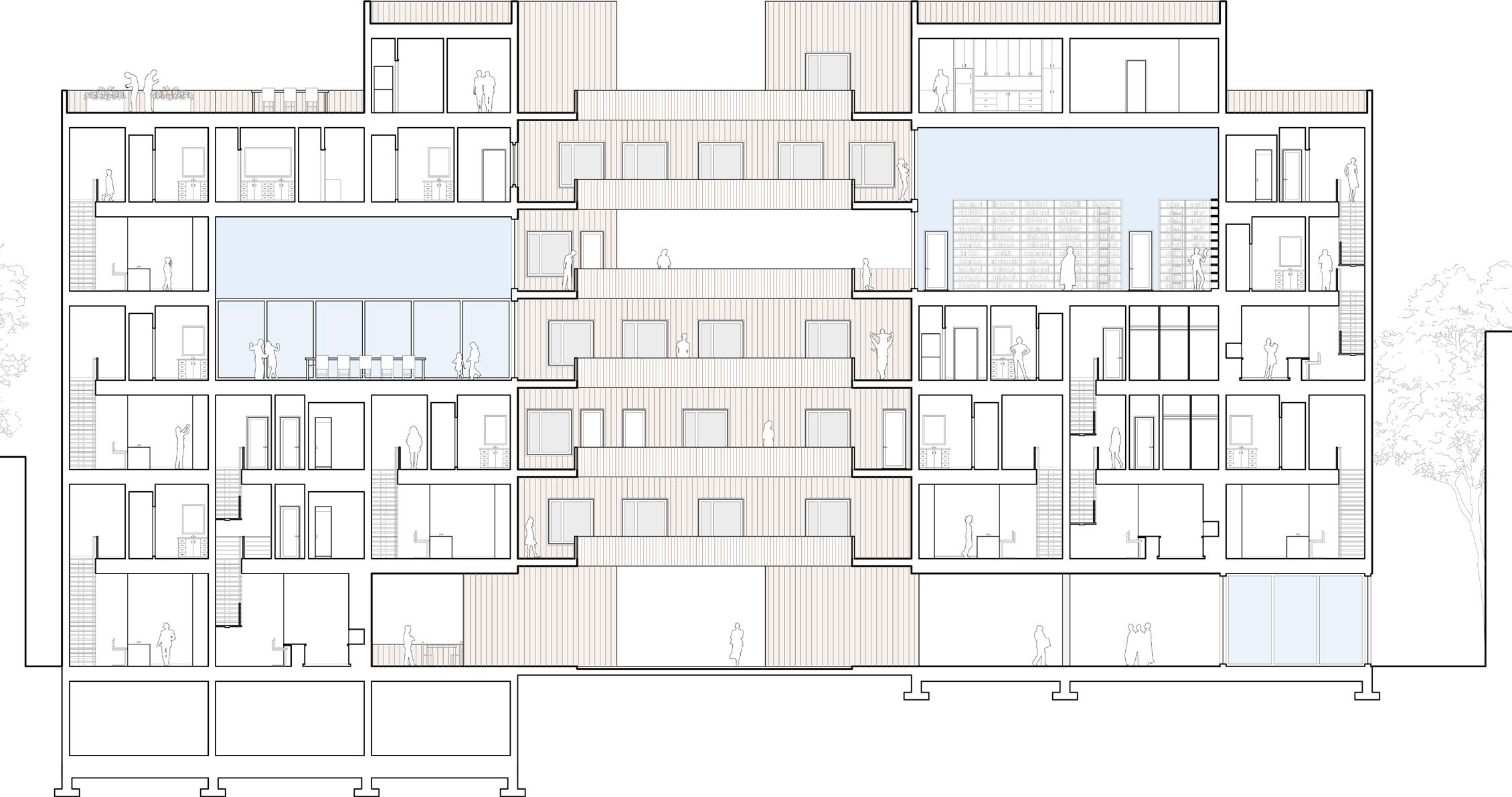
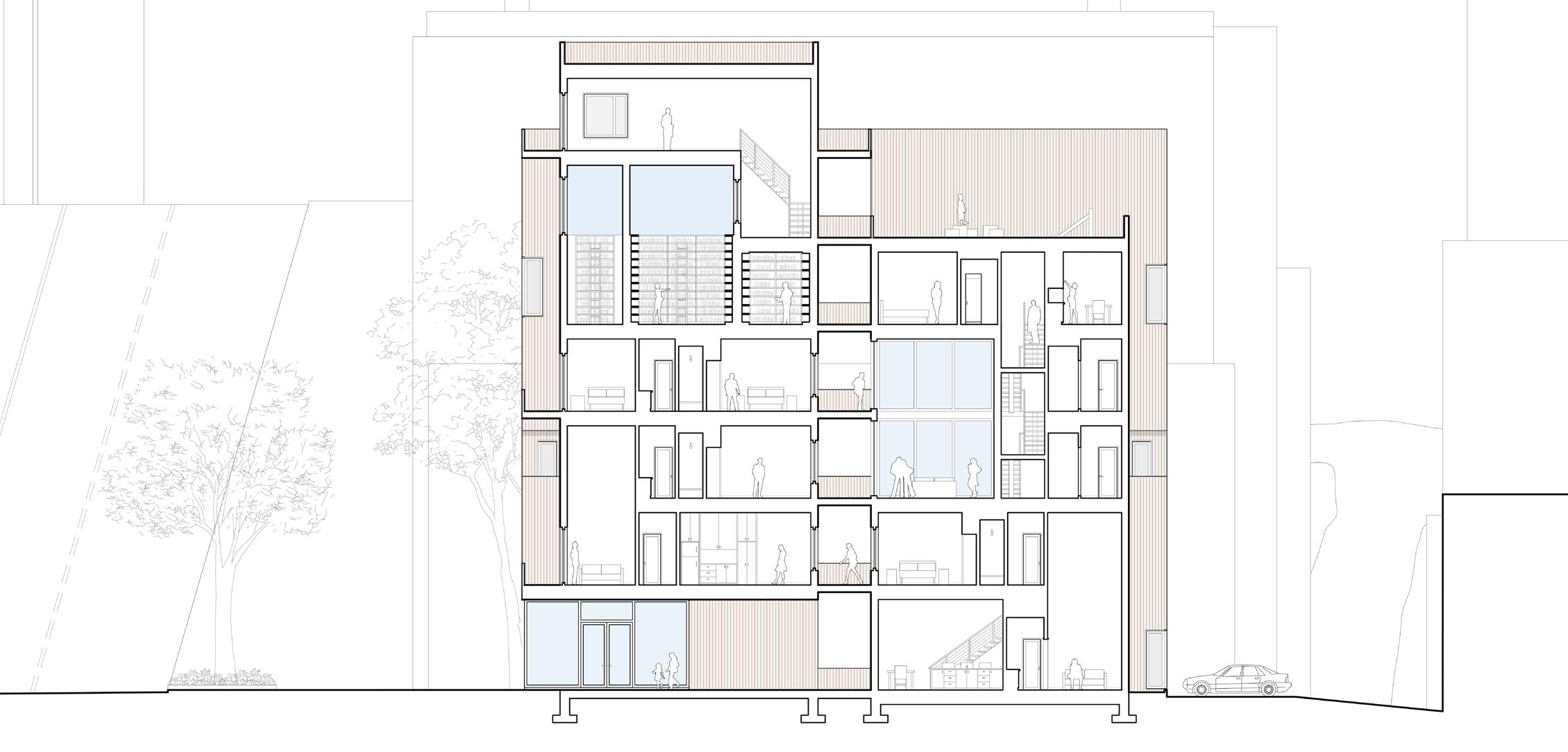
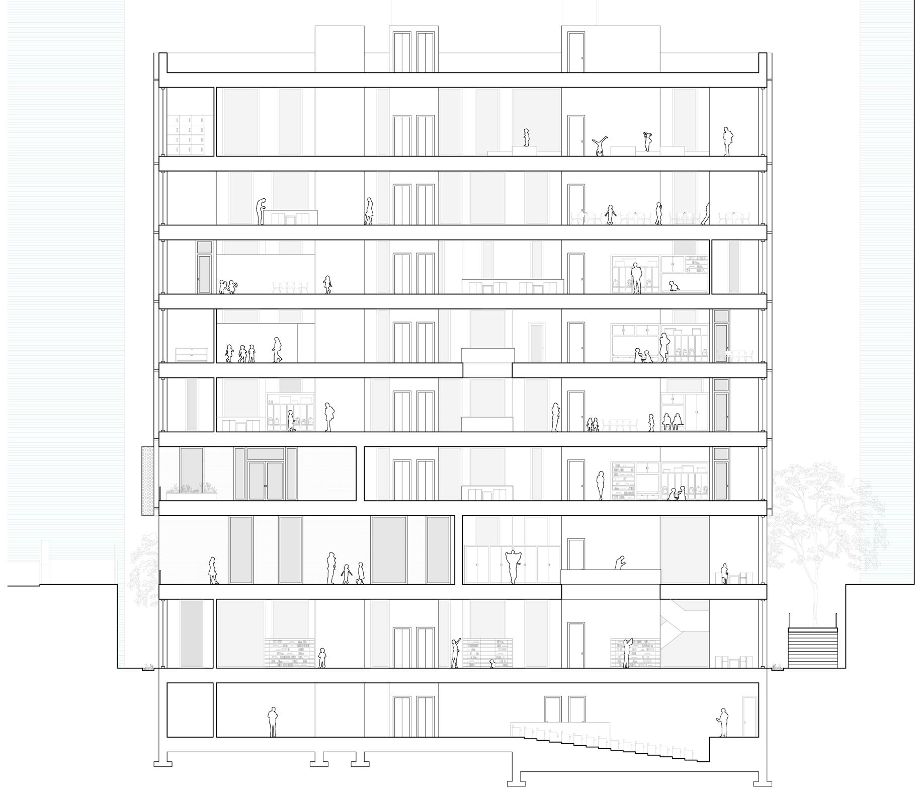
The color on the plans and section indicate the difference between private residences (brown) and communal the ground floor are shared spaces for residents of the building and the public. For the residents, there is a lobby, communal work space. The public can utilize the ground floor cafe, exterior seating spaces, and central courtyard, to pass through the exterior ground space to the street behind the building. The ground floor is meant to be porous connectivity from the metro stop, Connecticut Avenue, to Rock Creek Park beyond. This contrasts the neighboring do not have publicly accessible pass-throughs. At the rear of the building, there are a few above ground parking ample bike parking. The limited parking is meant to both reduce the cost of the building and encourage residents sustainable transportation options by use of the Washington Metro station that is directly across Connecticut
Row House as a Unit
Cluster Row House
Aggregate Clusters
Stack Clusters
Flip Row House and Carve Communal Space
space (blue). On lobby, mail room, and courtyard, and are invited porous to increase neighboring buildings that parking spots as well as residents to seek more Connecticut Avenue.
Fourth Floor Plan
Third Floor Plan
Second Floor Plan
Front Exterior
Space Rendering
Communal
B-B
Section
Section A-A
Axonometric of Rear of Building
BUILDING BLOCKS
PROJECT TYPE: ELEMENTARY SCHOOL
LOCATION: CHICAGO, IL
SPRING 2024 FOUNDATION STUDIO 2
PROFESSORS JEANA RIPPLE AND KATIE STRANIX
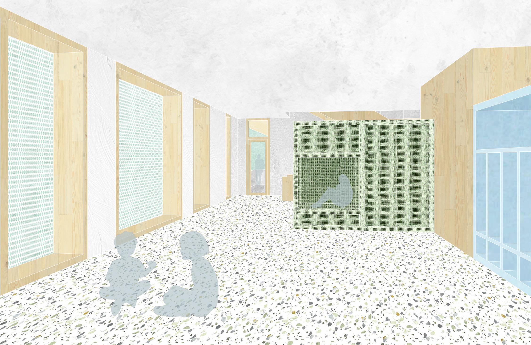
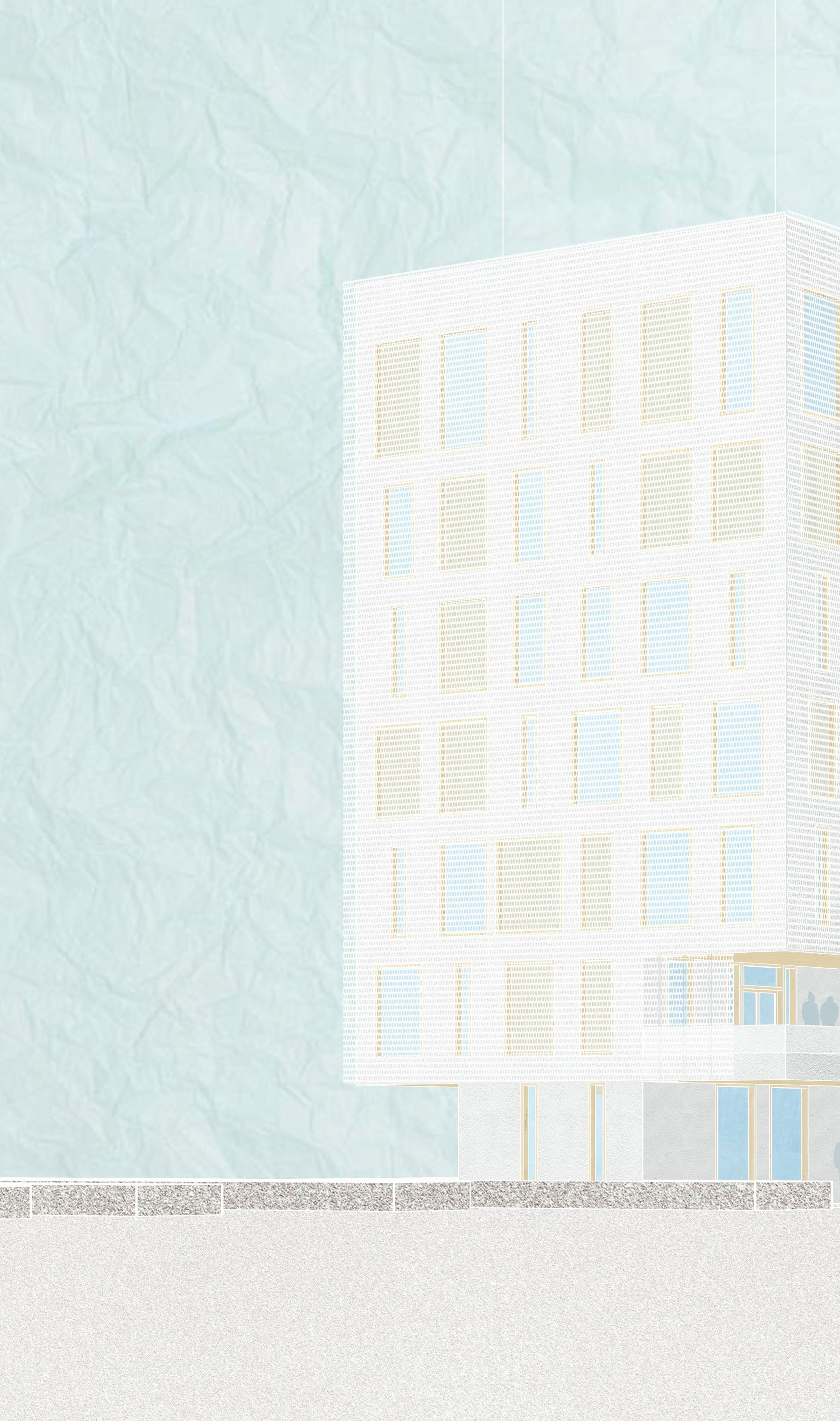
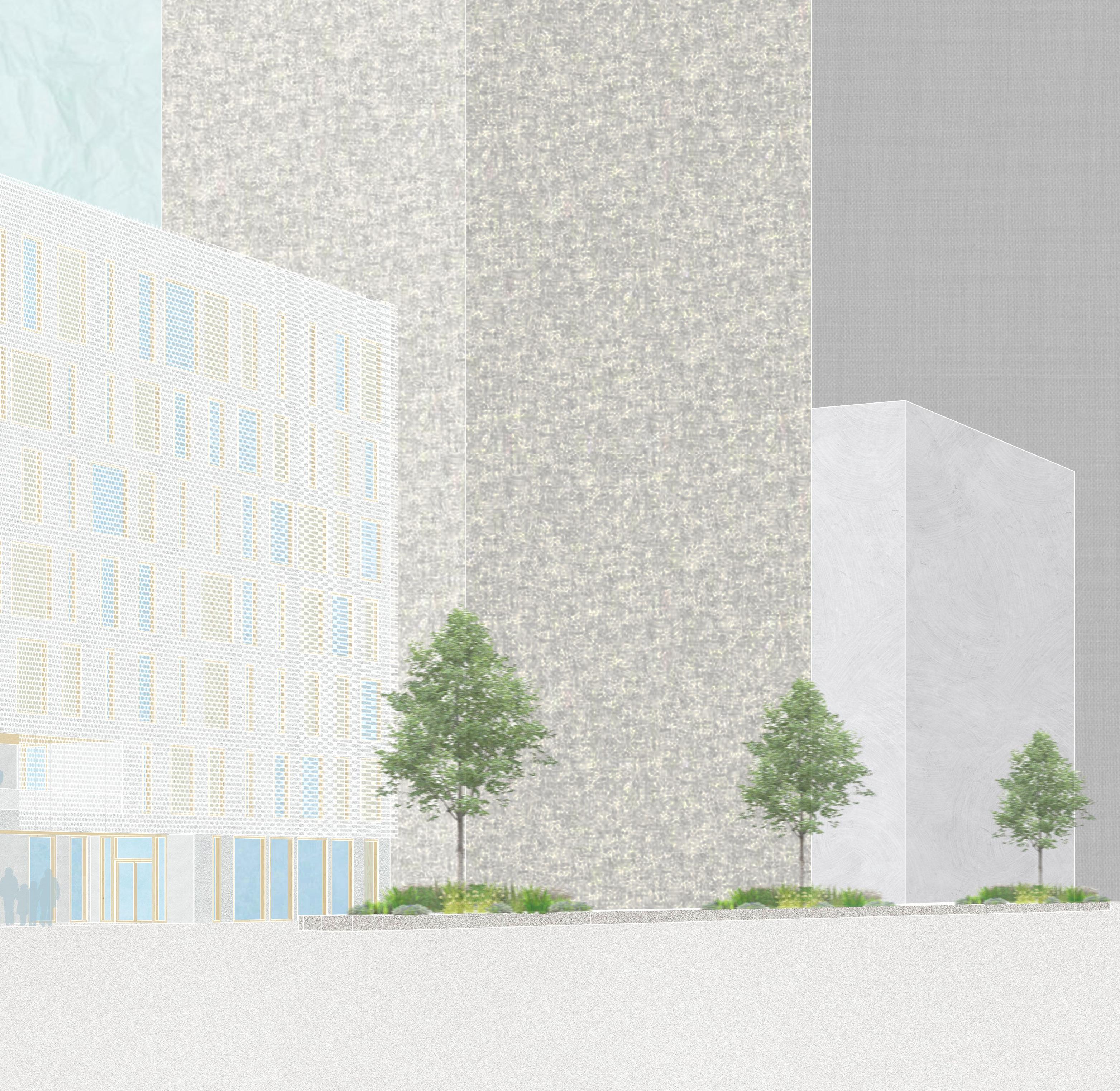
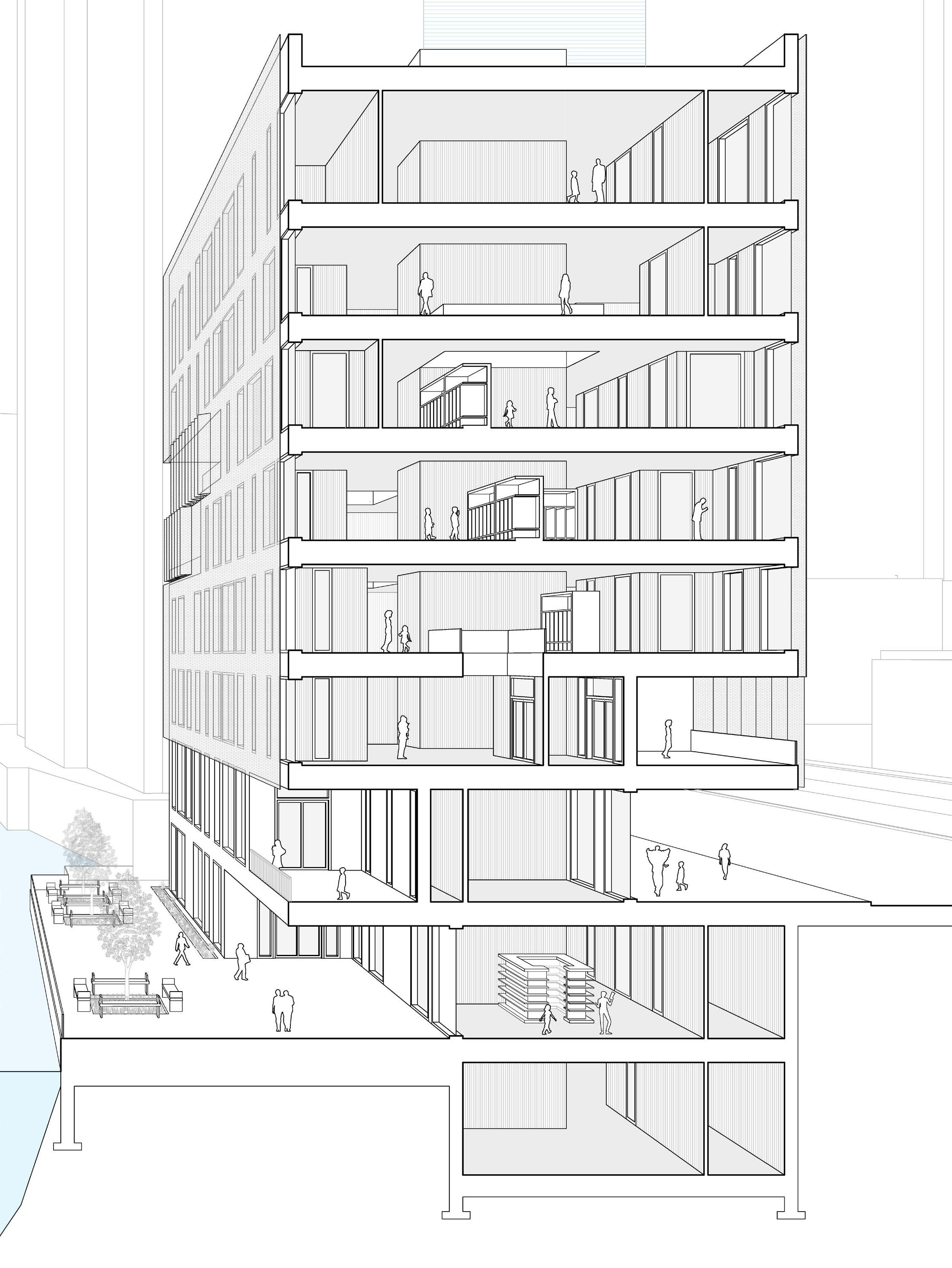
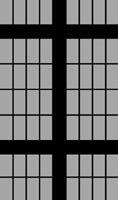
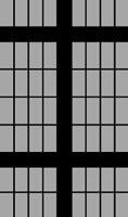
This design proposal is for a Reggio Emilia elementary school along the Chicago River. The design draws on the modularity of brick and a grid similar to the Chicago Frame, and the concepts are further expanded to create a series of nested rectilinear volumes that shape the school’s exterior and interior.
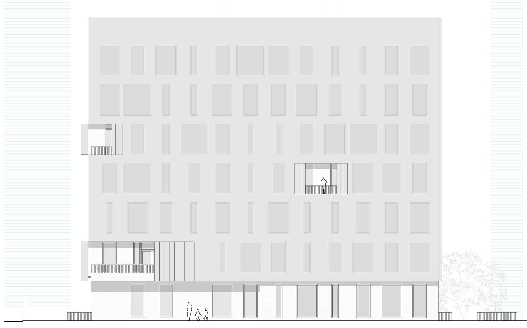
The first layer of nesting occurs in the exterior of the building through a screen system that wraps around the entire building but pulls up at the street and river-level entrances into the school. Along the balconies, the screen panels are operable to allow these spaces to open up to the river and city. The porosity of the screen panels varies depending on interior programming. For example, the screen is more opaque outside the windows into bathrooms and more transparent in front of larger windows that provide views of the river.
One of the primary Reggio Emilia principles explored in this school design is transformability, which allows for customizable spaces that can adapt to students’ and teachers’ needs. The outer band of the building has set spaces with specific programs, these spaces are meant to be a break from the collective. The central spaces created between the outer band of rooms are transformed by movable furniture pieces that create partitions between classrooms. These central, shared spaces are similar to the Reggio Emilia’s central piazza and are meant to foster group interaction.
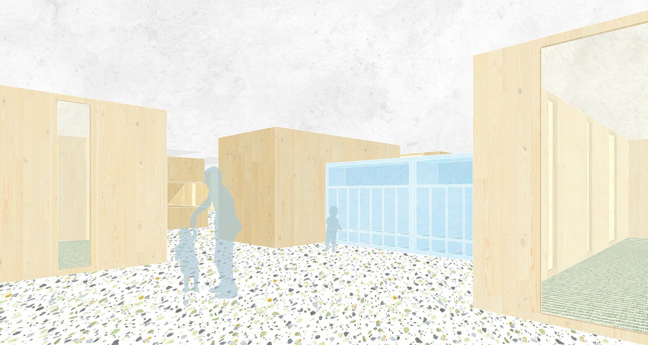
Interior Rendering
Front Elevation
Set Program Rooms
Movable Furniture
Collective Zones Between Rooms and Furniture
One of the primary Reggio Emilia principles explored in this school design is transformability. This allows for customizable spaces that can adapt to students’ and teachers’ needs and allow for flexibility of use. The outer band of the building has set spaces with specific programs, while the central spaces are transformed by movable furniture pieces that create partitions. These central, shared spaces are similar to the Reggio Emilia’s central piazza and are meant to foster group interaction. These ideas eliminate the need for set corridors and provide a more uninterrupted flow of space throughout the building. There is also an emphasis on the atelier. Each floor has shared spaces for art and experimentation in order to support each student’s learning and creative processes.
Fifth Floor Program Diagram
Small Group Space
Pottery Room
Quiet Time Room
Light Play Room
Art Storage Room
Bathrooms
Circulation
Collective Space
Transformability Diagram
Second Floor Plan
Seventh Floor Plan
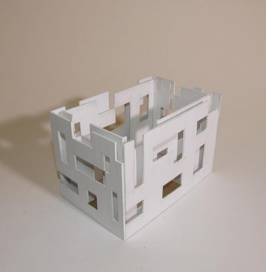
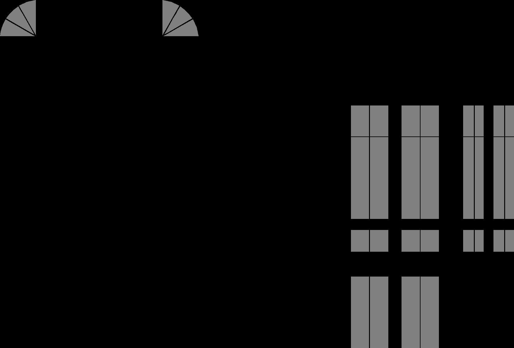
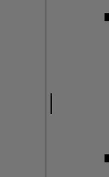
These process models redesign the Chicago Frame as massing and planar models and explore ideas of carving, connected exterior spaces, and punctured facades, which are ideas carried throughout the proposed design.
Exterior Rendering
FRACTURED AND FOUND
PROJECT TYPE: SCHOOL ARCHIVE
LOCATION: CHARLOTTESVILLE, VA
FALL 2023 FOUNDATION STUDIO I
PROFESSOR KYLE SCHUMANN
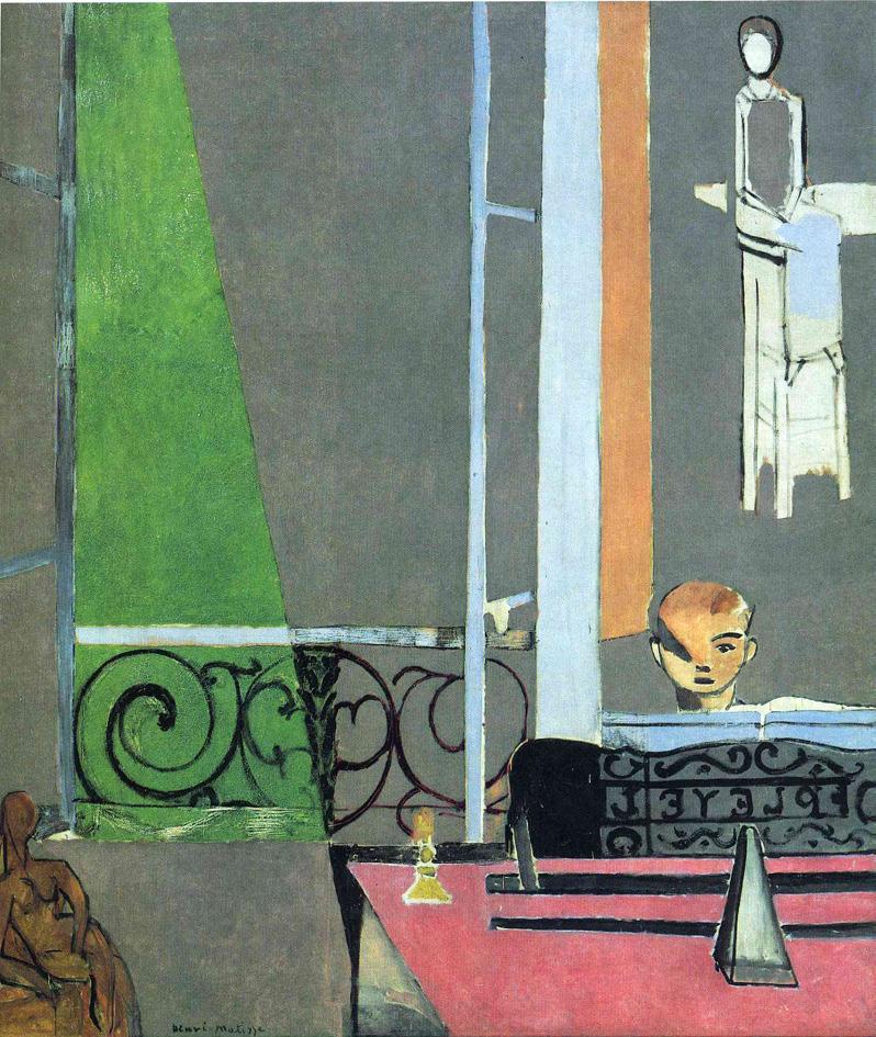
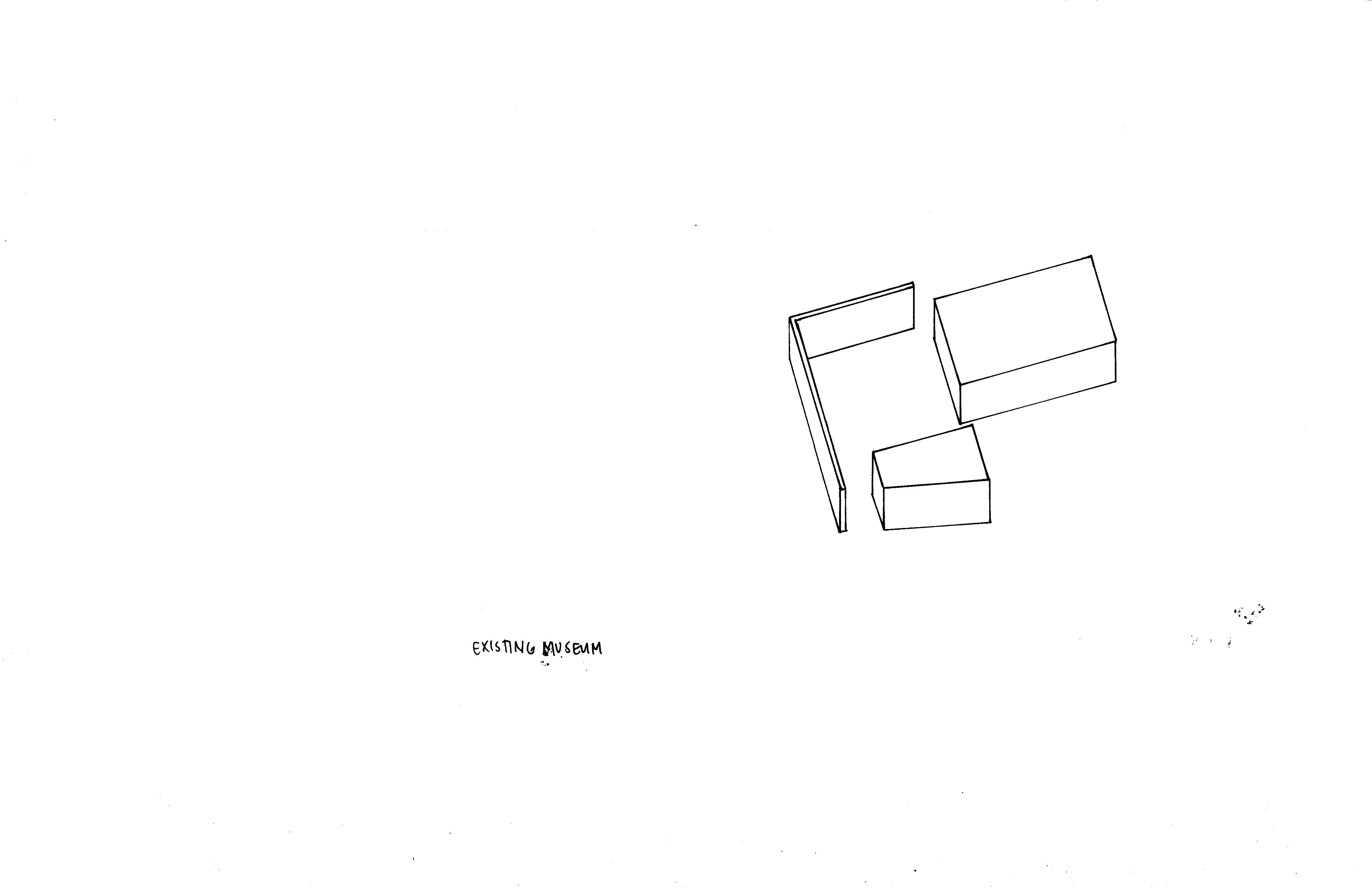
This project serves as an archive to collect, display, conserve, and examine the hidden influences on Observatory Hill at the University of Virginia and process the site’s history within the evolving narrative of the University. This is made possible through several types of programs, including the archive, dialectic, administrative, supporting, and landscape spaces. This project is supported by a series of assignments that were crucial to the design process. These previous assignments include an analysis of Matisse’s “The Piano Room” and Odile Decq’s Museum of Contemporary Art in Rome, and an assignment that synthesized the two to create an ambiguous “room”.
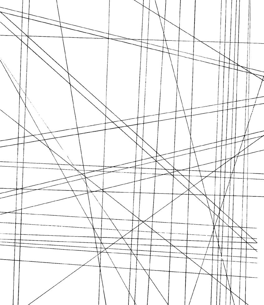
Three primary sets of lines inform the project’s spatial organization. The first set of lines is from UVA buildings and Charlottesville buildings, one of which forms the facade, and the other breaks it apart. A second series of lines inform the continuous wall organization across all floors. These lines extend into the landscape to create a terraced outdoor that bleeds into the existing topography. A third set of lines, which is a rotation of the previous set, determines the ceiling pattern, which consists of volumes that shift down to impact levels of expansion and contraction.
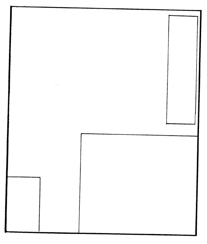
One of the primary features of the archive is a gallery space located on the ground floor of the first building; this space is intended to be an entrance to the larger building. The ground floor building south of the gallery is intended as a student space. To the east is an administrative building. The northernmost and southernmost buildings are circulation spaces. All ground-floor buildings are centered around a courtyard. The lower floor includes conservation and restoration laboratories for maintaining found items on Observatory Hill, additional study spaces, a visiting faculty apartment, and mechanical. It also serves as an extension of the gallery, providing artifact storage and further display shelves.
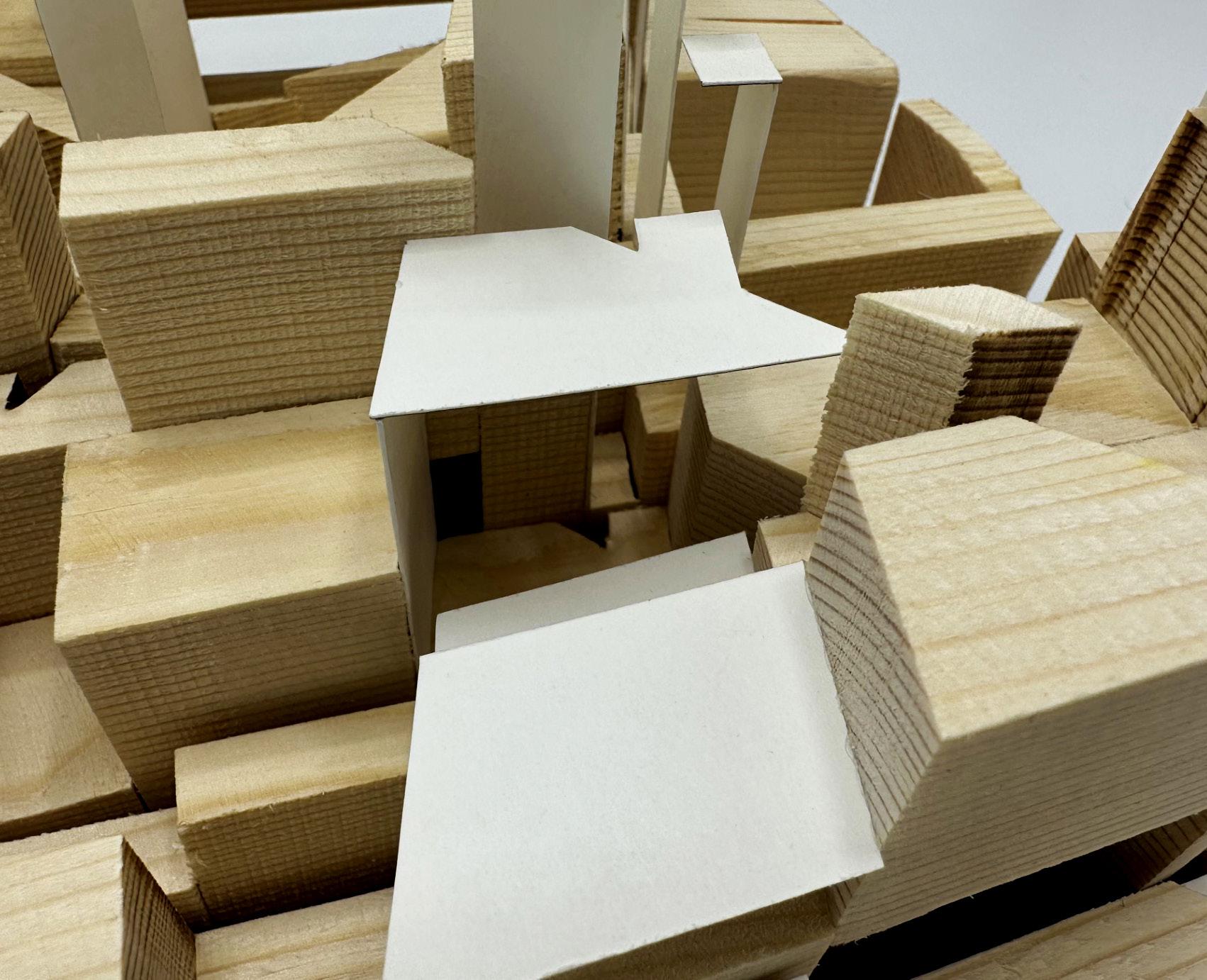
Model Photo
Main Subjects Diagram
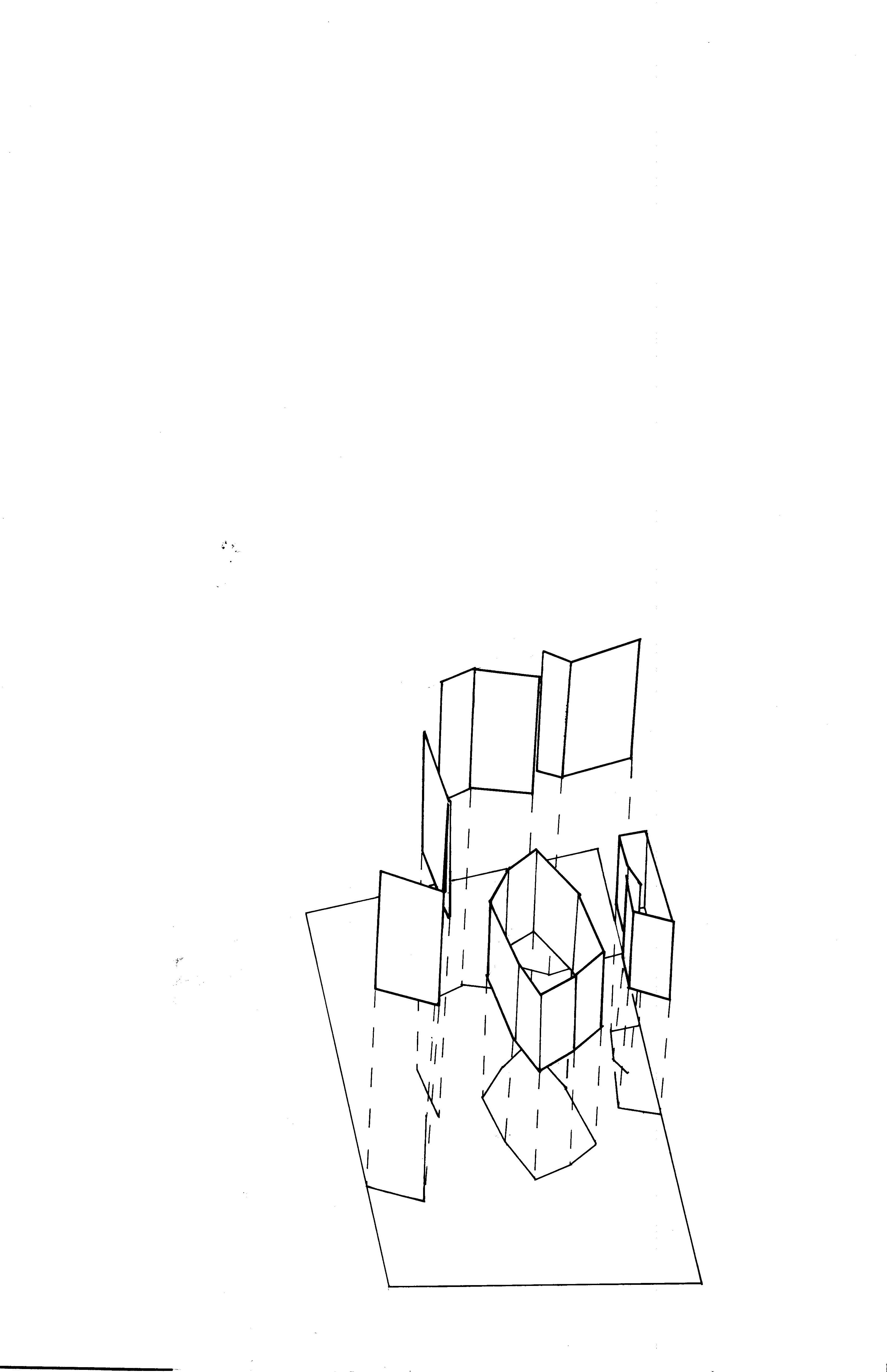
Construction Lines Diagram
“The Piano Room” by Matisse Light versus Dark Diagram
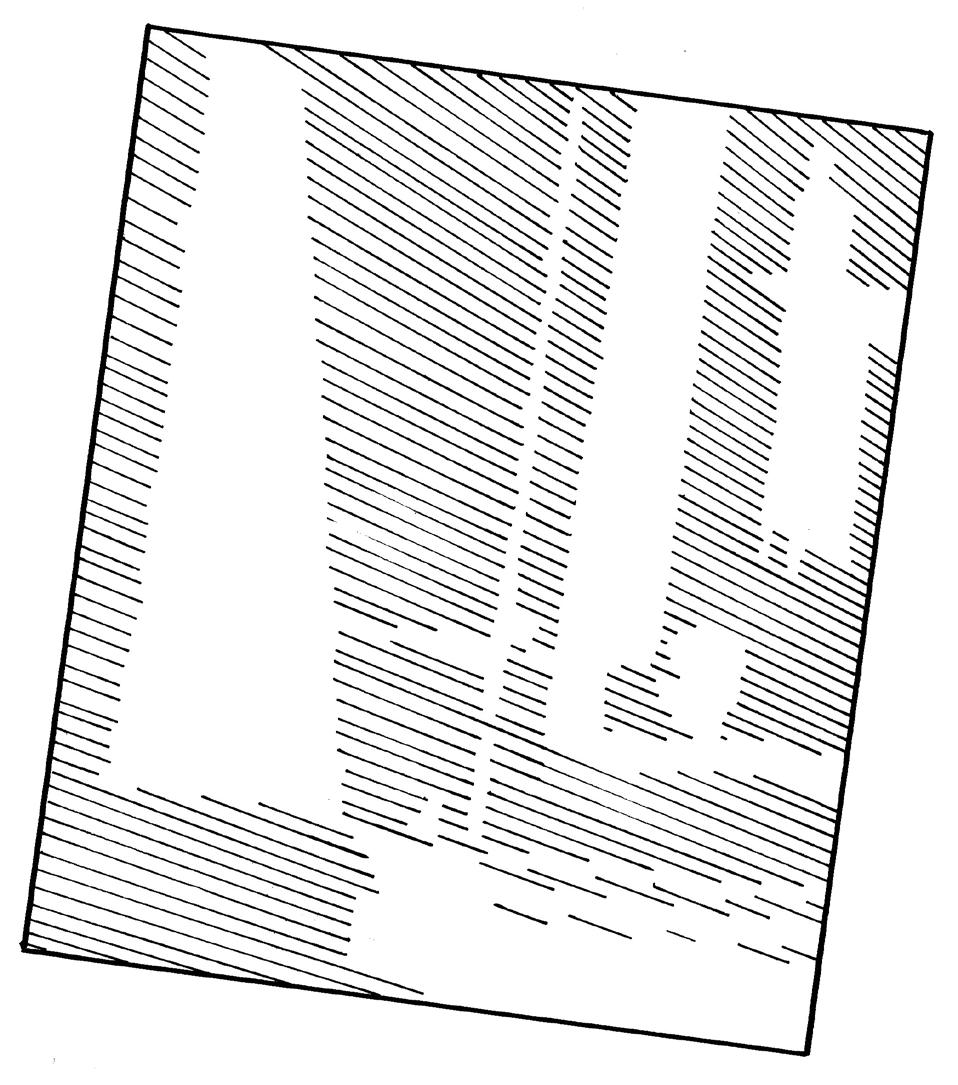
This exercise analyzes “The Piano Lesson” through various modes of representation to understand further the painting’s structure, geometries, figures, and spatial logic. To begin, a series of quick diagrams explored topics such as circulation, construction lines, and the main three subjects in a simplified way. A section was cut through the construction lines that imagines how these lines might be transformed into a space. This section became inspiration for the proposed archive, specifically experimenting with building below a ground line and creating spaces of various scales.
SECTION B-B
1" = 1"
Diagram Section
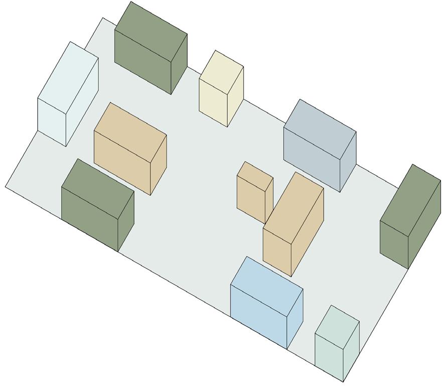
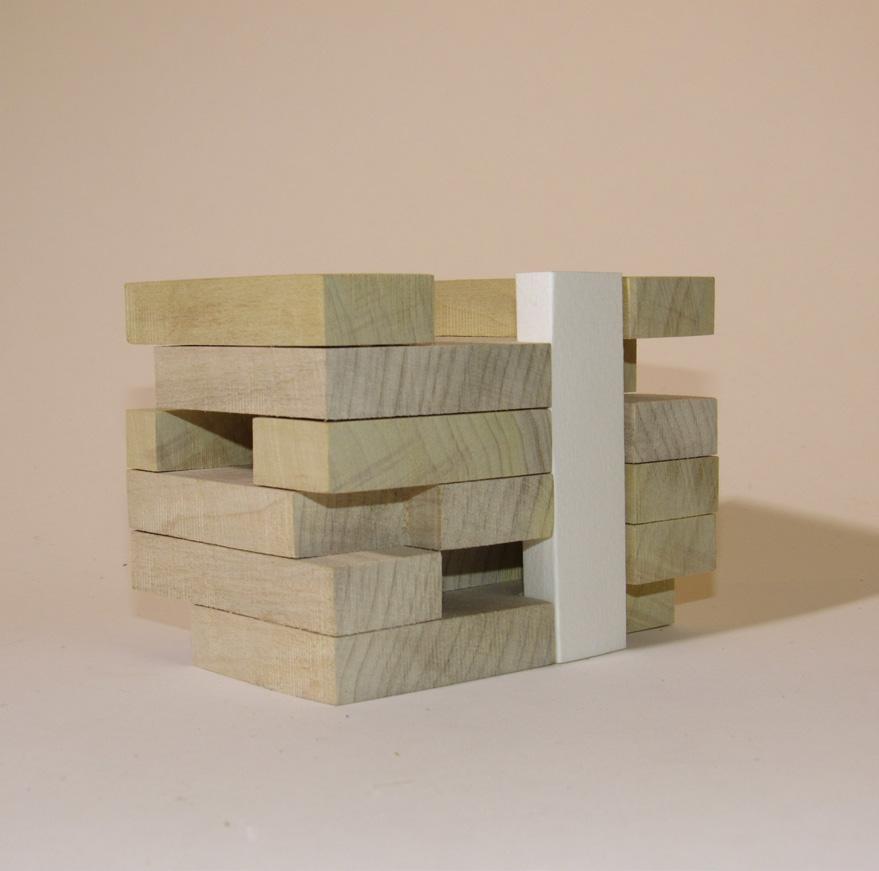
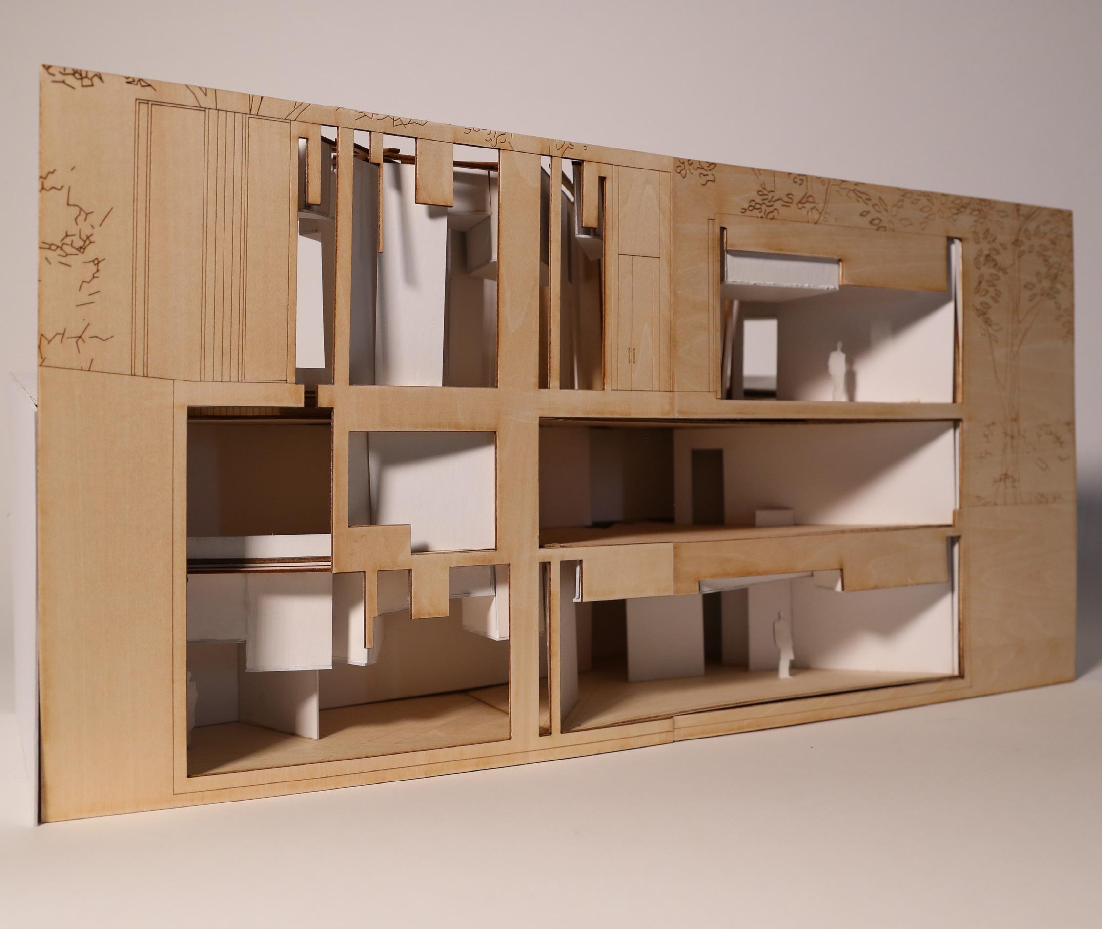
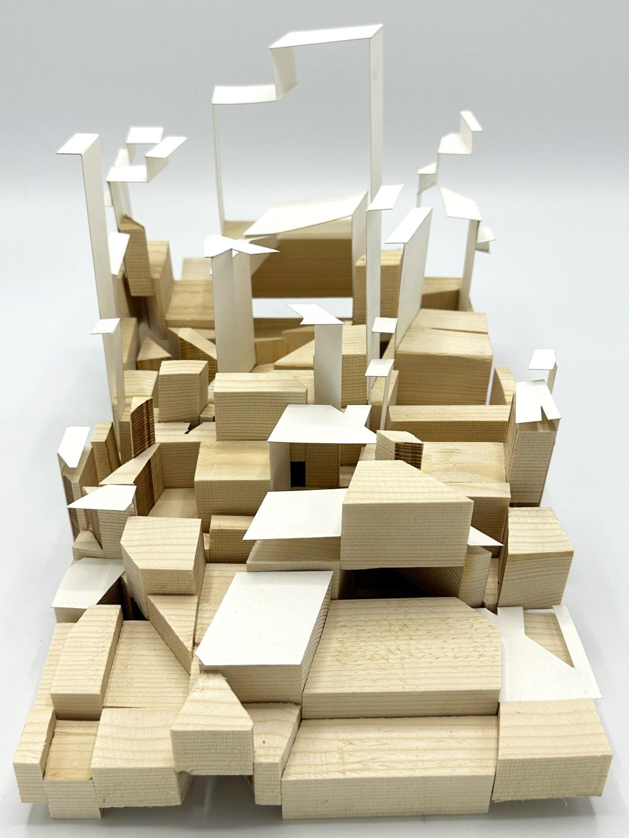
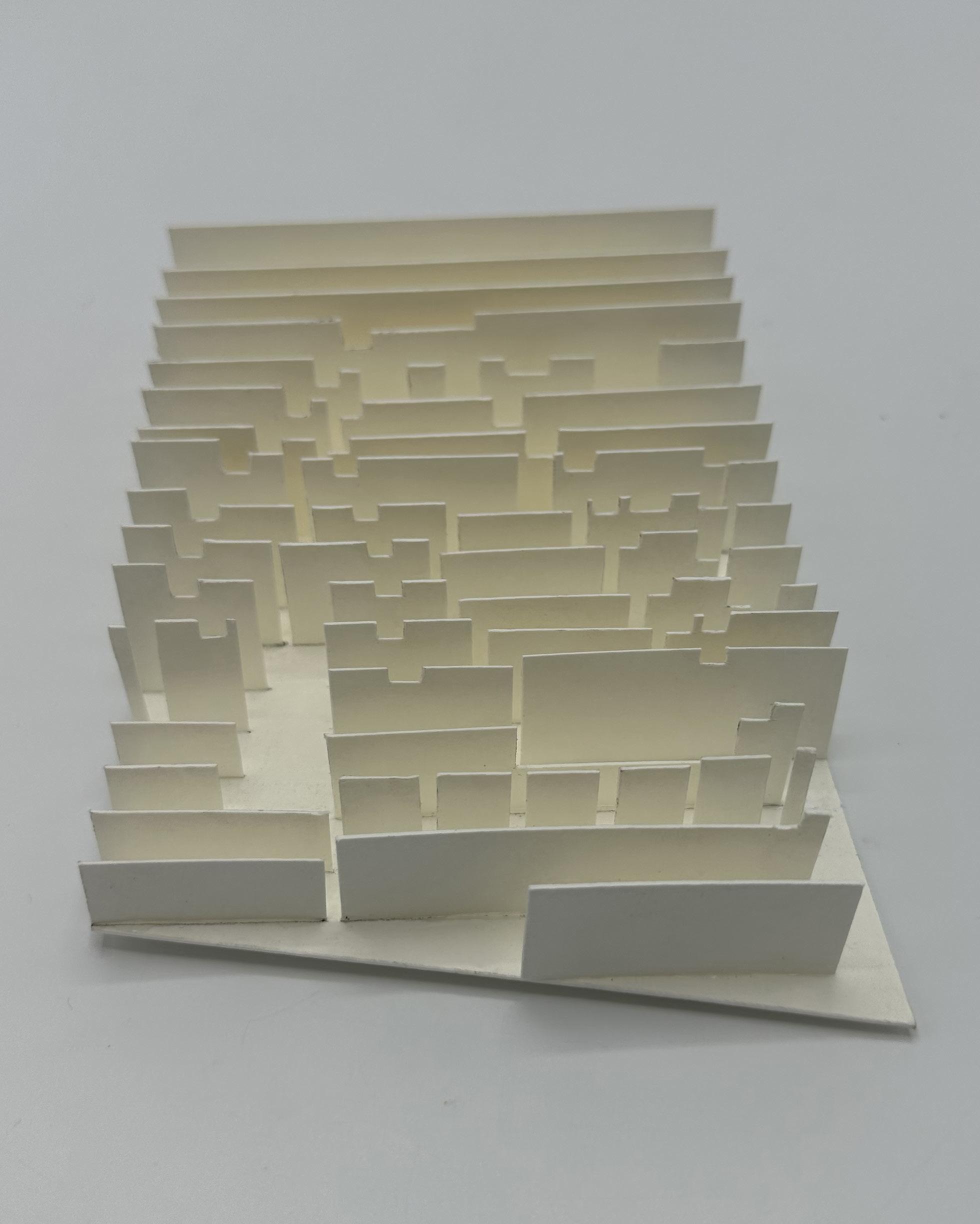
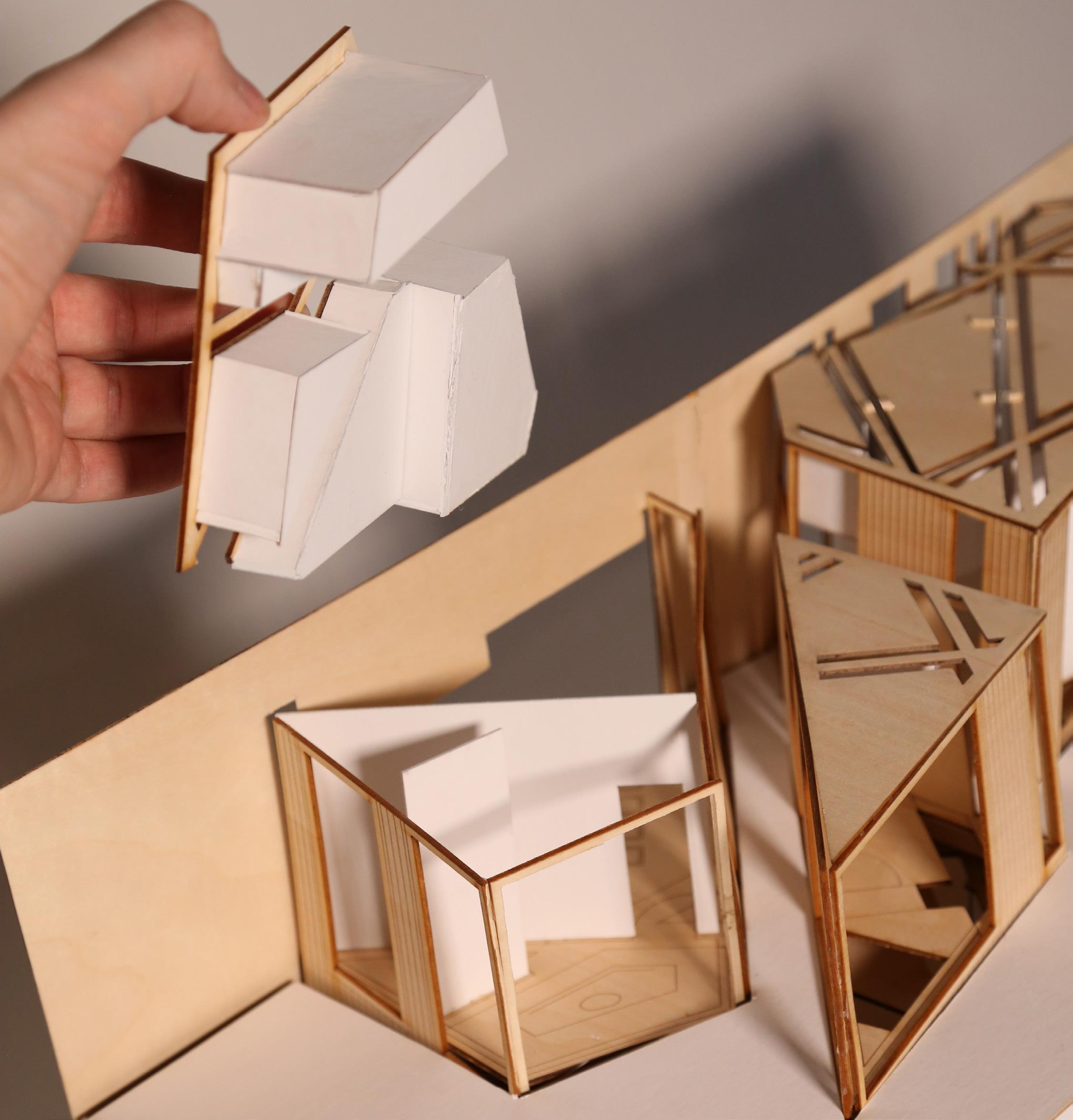
This model expands upon the previous diagrams of construction lines to imagine what might be beyond the paper. Additionally, the idea of an edge and larger spatial context was explored through material change in the model. This model is comprised of wood blocks and planar paper elements. The wood blocks inform the ground plane, while the lighter paper elements create spaces around the blocks and extend above ground and into the surrounding environment. The model has 10 sections, informed by construction lines from the previous diagrams.
Construction Lines Diagram Represented as a Model
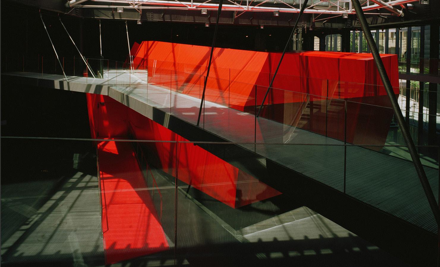
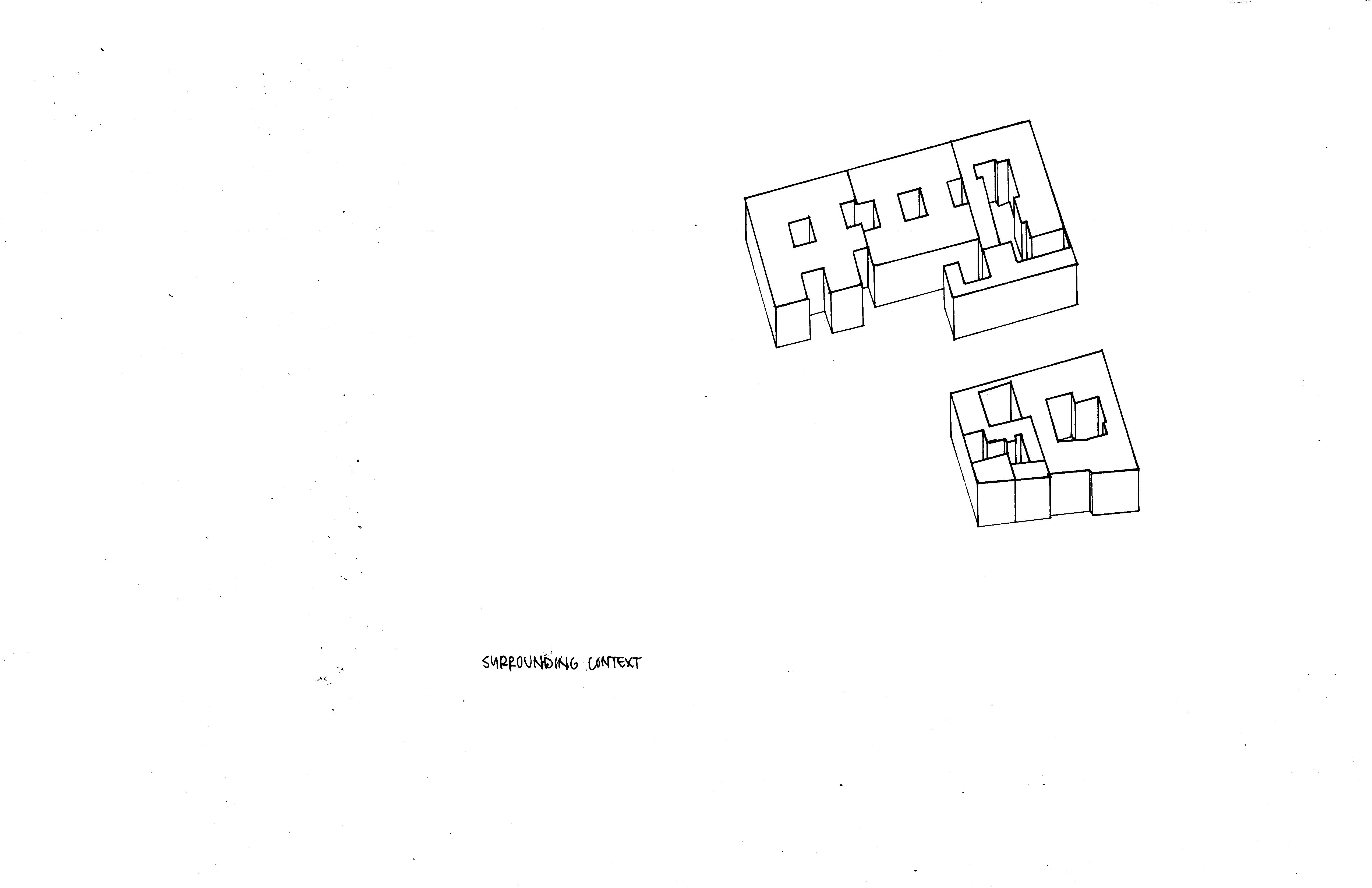
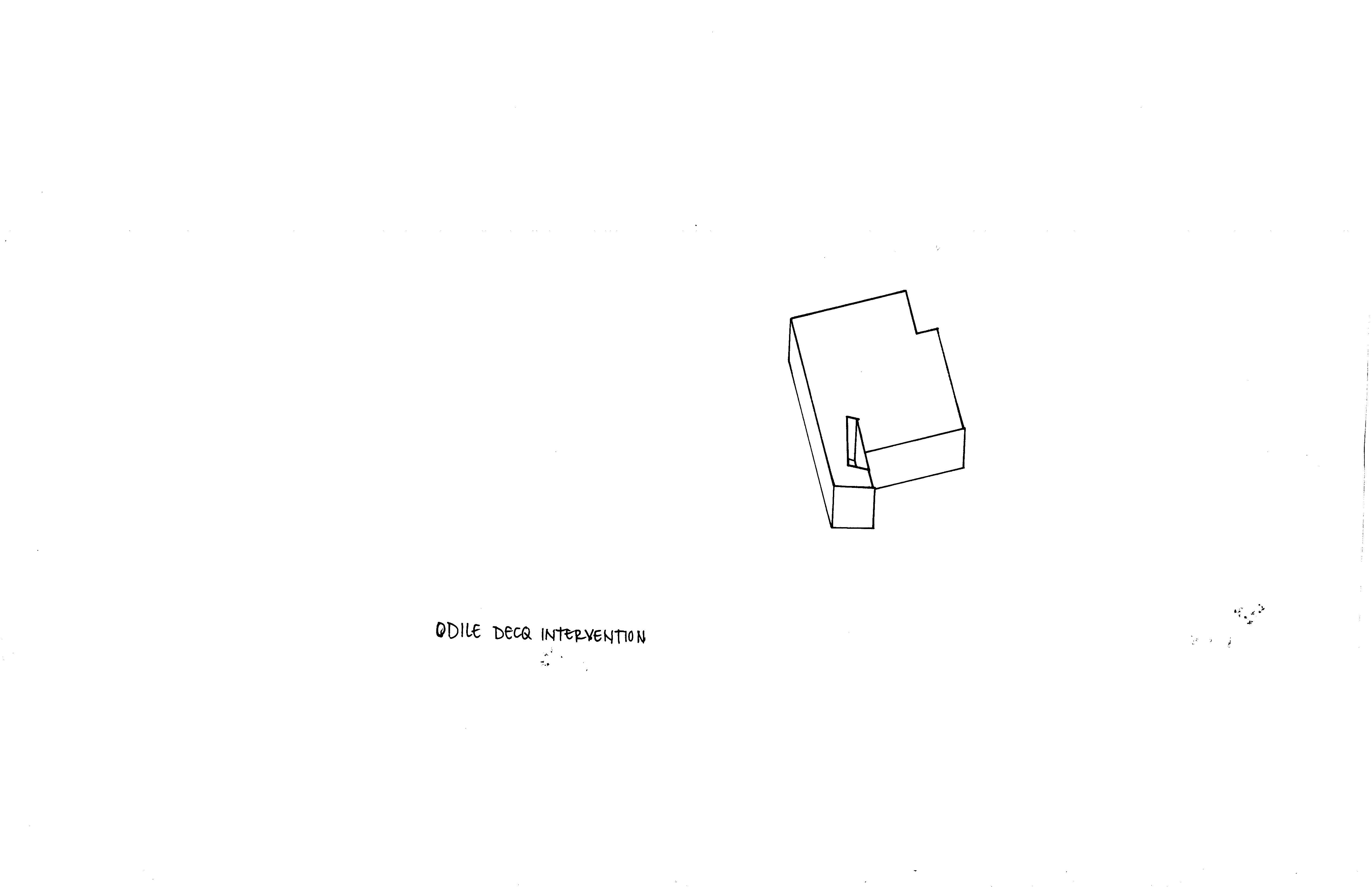
This exercise aims to analyze the spatial organization and principle elements of the Museum of Contemporary Art in Rome through series of axonometric drawings and diagrams demonstrating ideas such as existing context, nesting, passive spaces, and flow. From these diagrams, models transform the two-dimensional diagrams to three-dimension.
Gallery Walls Axonometric Drawing
The Museum of Contemporary Art in Rome by Odile Decq
Nested Walls Axonometric Drawing
Odile Decq Intervention
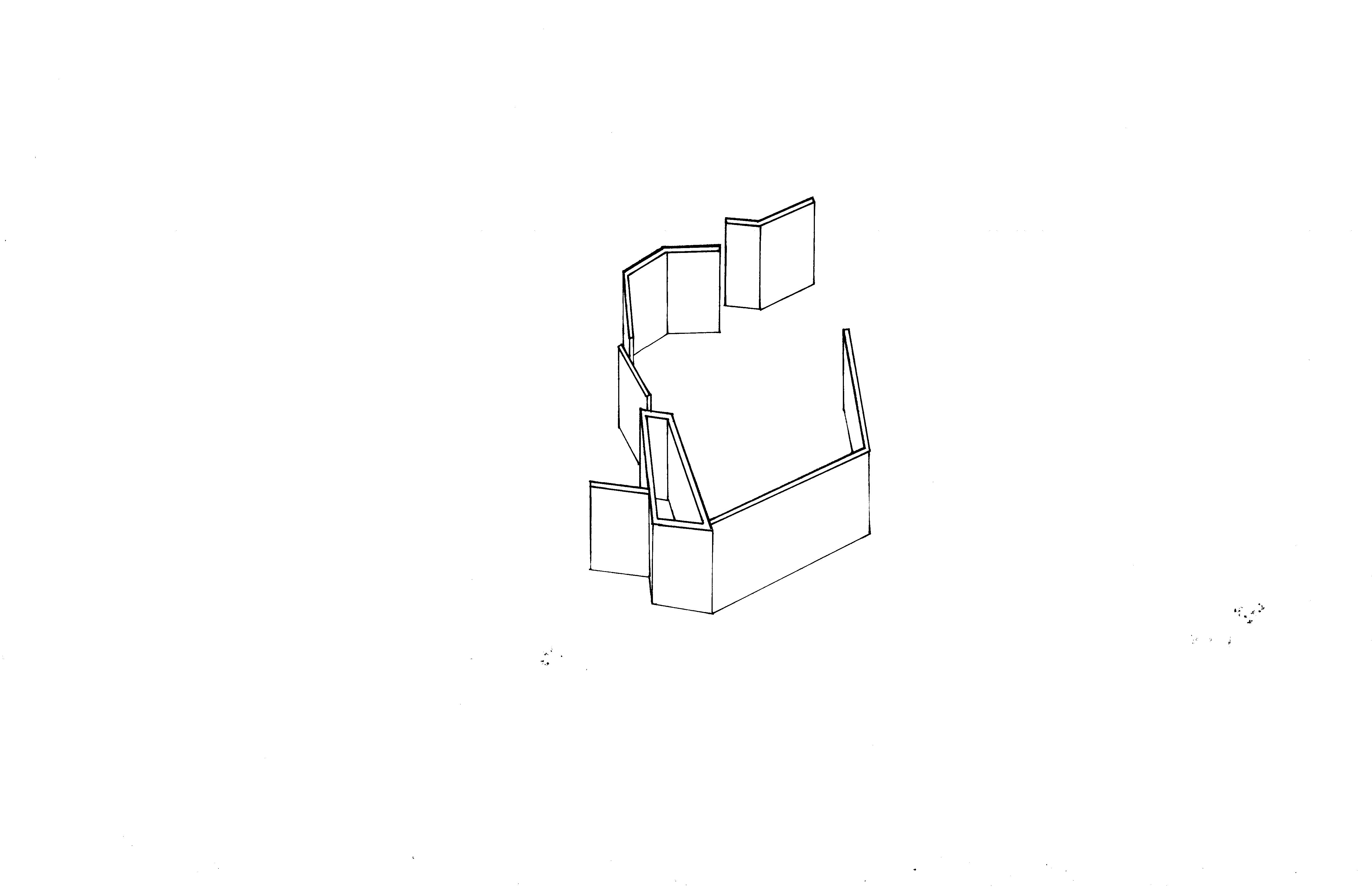
Flow Model
Room Project Transformation Series
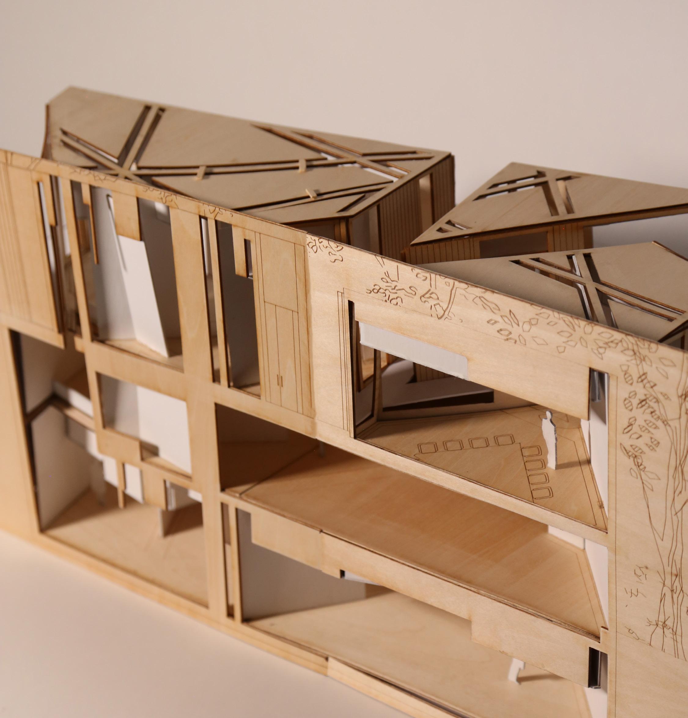
This exercise aims to create an ambiguous “room” with various experiences throughout the site that are conducive to an individual and a group. The primary idea behind spatial organization is the concept of shifting various volumes to create space. This idea draws on the previous diagrams and models. There are three primary components to this project: 1) volumetric elements that flow into the terraced landscape, 2) walls that provide structural support for the roof and further break up the spaces created by the volumes, and 3) roofs that have the same shape as the volumetric elements. Between these elements, a wide array of spaces is formed, each defined by its levels of contraction, expansion, light, and accessibility. The space’s cut lines are continuous. The primary path provides the easiest access mode to these gathering spaces; however, the user might choose to take a lesser journey there - filled with crawling and squeezing through the spaces. As an individual descends into the space, various levels of vertical and horizontal contraction define each step, pushing the person deeper and deeper. Additionally, the amount of light varies. When entering the space, there are no roofs, creating a well-lighted area. However, as you descend into the space, it becomes darker, both due to the addition of roofs and the descension into the ground. This ultimately leads to the deepest space, meant for gathering.
Room Project Section A
Room Project Section B
The previous exercises culminate in this proposed archive. One of the primary features of the archive is a gallery space located on the ground floor of the first building; this space is intended to be an entrance to the larger building. The ground floor building south of the gallery is intended as a student space.
To the east is an administrative building. The northernmost and southernmost buildings are circulation spaces. All ground-floor buildings are centered around a courtyard. The lower floor includes conservation and restoration laboratories for maintaining found items on Observatory Hill, additional study spaces, a visiting faculty apartment, and mechanical. It also serves as an extension of the gallery, providing artifact storage and further display shelves.
Building fragments into smaller pieces
Construction lines from UVA form facade
Construction line from Charlottesville bisects building
Building fragments in half
Shift and remove pieces
Building Transformation Diagram
Archive Section
Archive Sectional Model Photo
Archive Sectional Model Photo
UPPER EAST SIDE
TOWNHOUSE
PROJECT TYPE: RESIDENCE
LOCATION: NEW YORK, NY
SUMMER 2025
PETER PENNOYER ARCHITECTS
During my internship at Peter Pennoyer Architects, each intern developed a proposal for a townhouse on 81st Street to replace an existing parking garage. This block of the Upper East Side is characterized by distinguished architecture, including works by Peter Pennoyer and Delano & Aldrich. The proposed design aims to contribute to this historic streetscape, drawing inspiration from Delano & Aldrich while responding to its architectural context.
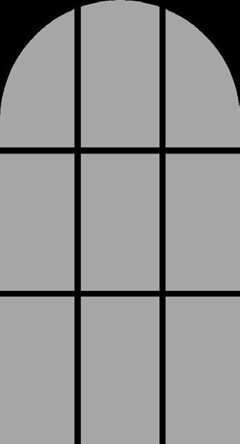
The townhouse is composed of brick and limestone, materials that harmonize with its neighboring facades. The design rises five stories above a cellar, matching the height of the nearby Peter Pennoyer Architects townhouse two doors east. The facade expresses a rhythm of rectilinear and circular motifs - seen in the arched door pediment, the brick and limestone window headers, arched double-hung windows, and ornamental ironwork.
The cellar accommodates service spaces for staff. The ground floor includes a grand foyer, guest waiting area, and kitchen. The second floor provides expansive entertaining rooms, including a dining room, living room, and large balcony. The third and fourth floors contain the primary suite and children’s bedrooms, while the top floor offers recreational spaces such as a bar with city views and a gym. At the rear, a landscaped garden extends the home’s entertaining spaces. In section, the rear facade is terraced, creating visual and physical connections to the garden on each level.
GEORGIAN RENOVATION AND ADDITION
PROJECT TYPE: RESIDENCE
LOCATION: NASHVILLE, TN
SPRING 2023
FARRIS CONCEPTS IN ARCHITECTURE
This 1930s Georgian house lacked character and refinement; therefore, our charge was to enhance the original structure with both function and beauty, lifting it from a mundane example of Georgian architecture to one of a more stately presence that complements the surrounding residences. In order to maintain the existing architecture, much research was done to find architectural elements that match the Georgian style. This included elements of symmetry and balance, the use of double hung windows, and a high attention to detail in all trim work and finishes. My scale of work included overall design development, maintaining communication with the client, interior designer, and contractor, and drafting all elevation and floor plans. The renovations and additions are featured in a darker line weight than the existing structure.
Side Door Detail
Front Elevation
Side Elevation
Rear Elevation
Side Elevation
INTERIOR ELEVATIONS
PROJECT TYPE: RESIDENCE
LOCATION: NASHVILLE, TN
WINTER 2022
FARRIS CONCEPTS IN ARCHITECTURE
These interior elevations are for the bathroom and closet of the primary bedroom of an estate in Nashville, TN. I was responsible for taking the plans and imagining them as elevation. It was important to match the exact existing trim work around the windows, doors, base, and crown, therefore, samples of the existing house were taken and digitally traced. When composing the new closet and bathroom build outs, it was important to maintain ornamentation that matches the intricate detailing in the rest of the house and increase the functionality of the existing room.
Building Section
Primary Closet Interior Elevations
Primary Closet Interior Elevations
Primary Bathroom Interior Elevations
Primary Bathroom Interior Elevations
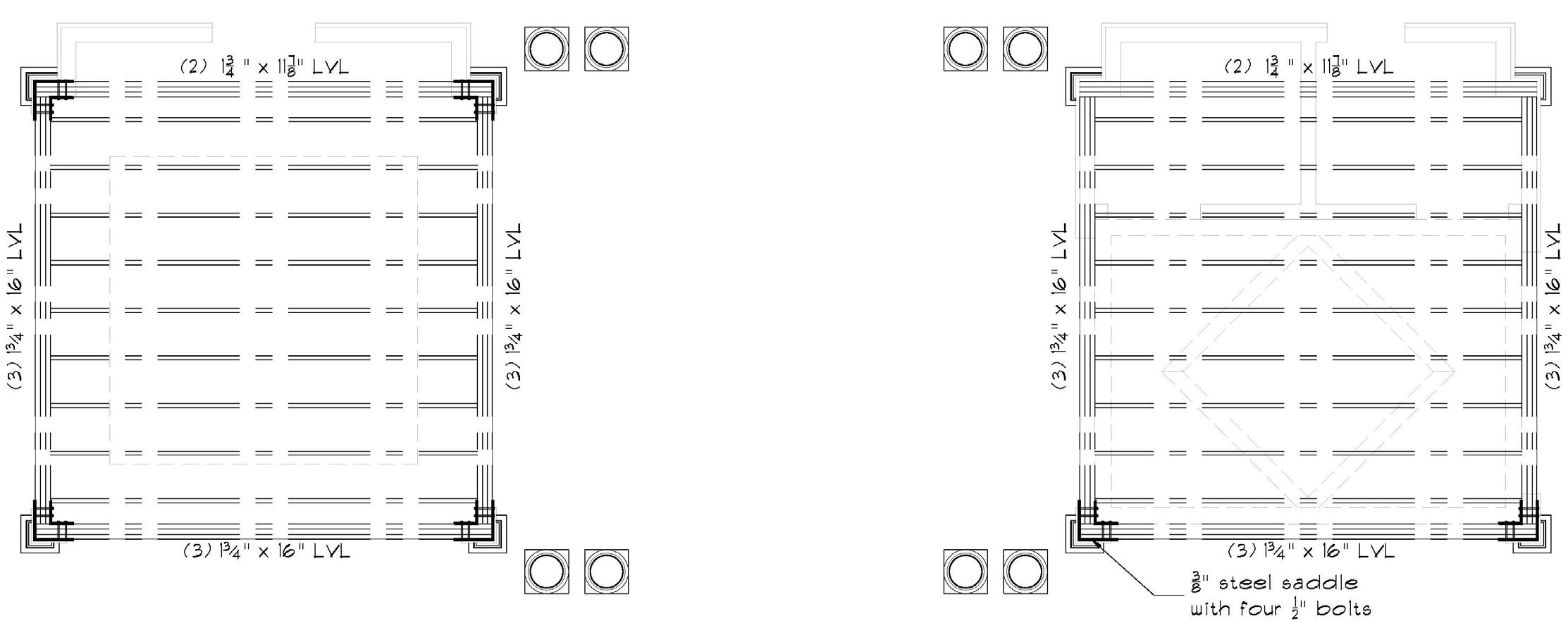
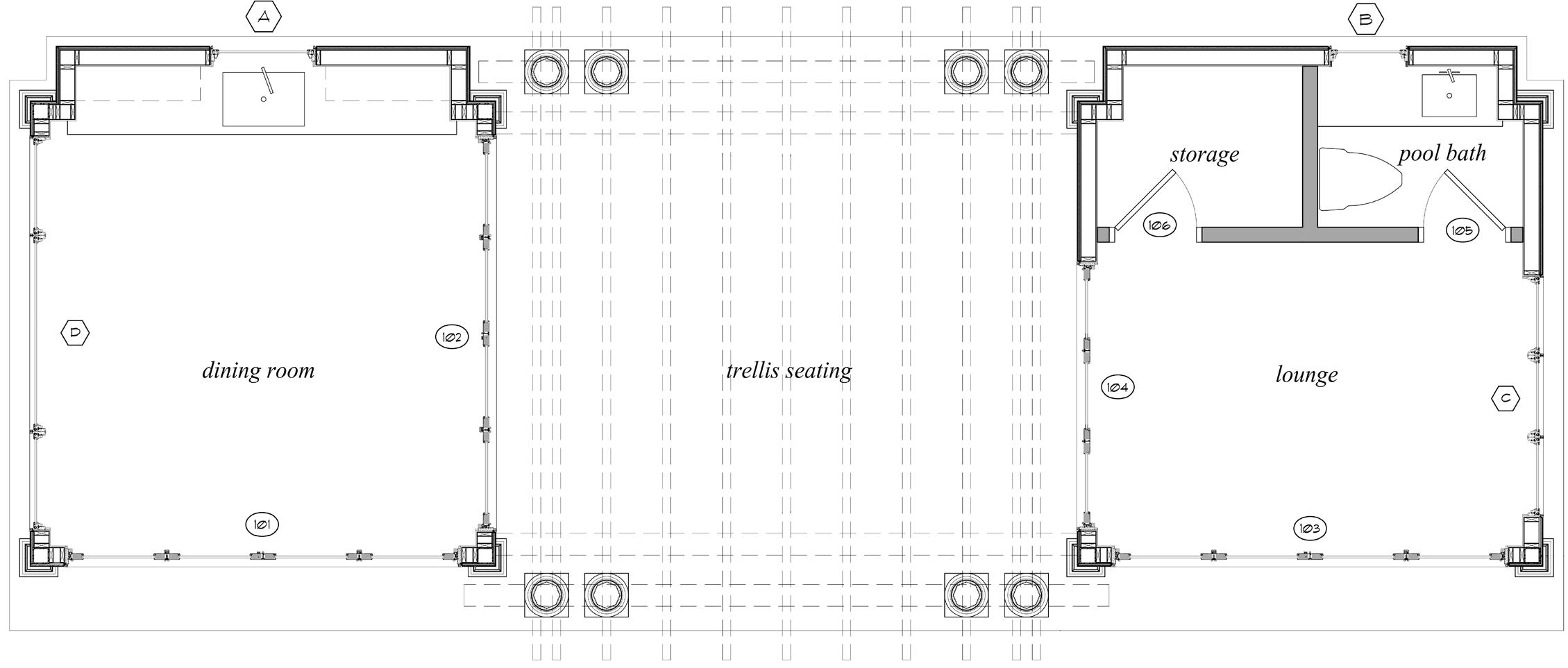
POOL HOUSE
PROJECT TYPE: POOL HOUSE
LOCATION: NASHVILLE, TN
SPRING 2023
FARRIS CONCEPTS IN ARCHITECTURE
This new build pool house complements the existing house through materials, trim work, and scale. A particular challenge when configuring the construction of the pool house was in the structural support. Due to the large folding doors on nearly every facade, additional support was needed to prevent deflection. I worked closely with the structural engineer to implement a solution of steel columns at each corner to support the weight of the roof, as seen in the construction details.