
THIS SENSOR TAP MUST BE INSTALLED BY A LICENSED PLUMBER IN ACCORDANCE WITH LOCAL REGULATIONS
This Nero sensor tap is manufactured to standard AS/NZS 3718.

Installation Instructions
MAX OPERATING PRESSURE.............................................................5 bar (500kPa)
RECOMMENDED OPERATION PRESSURE........................................1.5-5 bar (150-500kPa)
MAX HOT WATER TEMPERATURE .....................................................55°C
RECOMMENDED HOT WATER TEMPERATURE.................................50°C
Where water pressure exceeds 500kPa, a pressure reducing device is required to be installed. Note that water pressure overnight can reach 150% of the daytime pressure
NR402CH/NR402MB/NR402BN/ NR402BG/NR402GM/NR402BZ/NR402MW
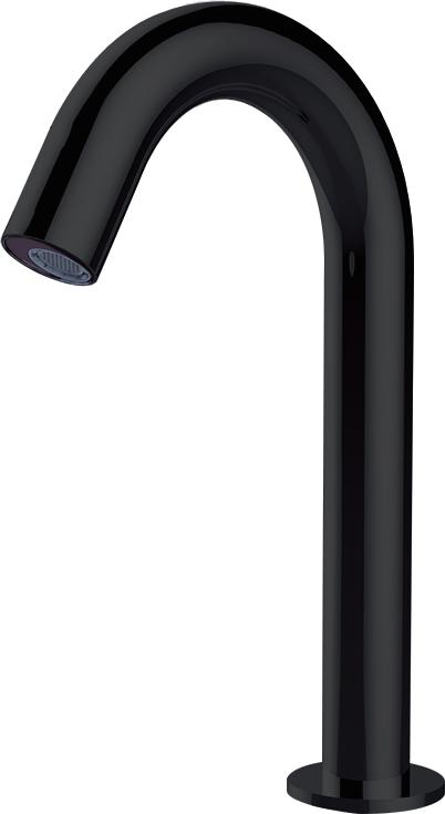
HOB MOUNT SENSOR TAP
CARE & MAINTENANCE
Clean with a soft cloth and warm soapy water as necessary - rinse and dry after cleaning. Under No Circumstances should abrasive or acid based cleaning products be used
PACKING INCLUDES
Before attempting any work involving mains water supply lines, ensure the water supply is shut off.
Stop valves (preferably with filters) must be used when installing your Nero tap to allow isolation. Failure to do so where required will void warranty.
This sensor tap must be installed in accordance with these instructions.
-1x sensor tap
-1x control box
-1x power adapter
-1x dressing ring
-1x flexible hose
-1x installation kit

rubber washer
Installation Instructions
General Note: This product is to be installed by a licensed plumber,installation must comply with AS/NZS 3500 and local plumb ng codes
Pressures & Temperatures
Maximum Hydrostatic Pressure – 500 kpa. (As per AS/NZS3500)
Note: AS/NZS 3500.1-2003 (Clause 3.3.4) states that “Provision shall be made to ensure that the maximum static pressure at any outlet, other than a fire service outlet, within a building does not exceed 500 kPa.
Note: Pressures above 500kPa can cause damage from water hammer, reduced life of appliances, taps and fittings, and cause excessive noise in the system.
Minimum Hydrostatic Pressure – 100 kpa
The Maximum operating temperature for the Senser Tap is 55℃.
Please ensure that the lines are flushed prior to installation as contaminates in the water can damage the flow regulator and also affect the performance of the Sensor.
Safety- DO NOT connect unit to mains power or turn on mains water supply until Sensor tap and control unit is fully installed.
1. Remove product from packaging and check for damages, if the product is damaged do not install and return to store of purchase.
2. The WELS compliant aerator has been pre-assembled into the tap outlet. To comply with WELS the flow regulator must remain in place.
3. Ensure product is complete as per exploded drawing.
4. A single 35mm hole is required in the mounting surface.
5. Remove Lock nut and thick rubber sealing washer from spout.
6. Put the Inlet hose and signal cable through the mounting hole ensuring thin bench sealing washer is in place on the base of the spout.
7. Assemble thick washer and lock nut to spout and tighten
N.B Spout thread has two flats to allow for spanner engagement to hold spout in place while tightening lock nut.
8. Position Control box on wall considering length of Spout outlet hose and signal cable. Control unit must be within 500mm from Basin, refer to Diagram (5) & (6) for correct positioning of control box. Using wall toggles supplied or suitable wall toggles and screw to suite wall material fit control box to wall. Ensure control unit is fixed to a vertical wall in a position away from moisture and is always kept dry.
N.B Control box must be installed with inlet thread to Right, outlet thread to the bottom on a vertical wall, do not assemble in a horizonal position. Diagram (1, 5, 6)
9. Fit spout outlet hose to control box outlet 1/2" BSP thread. Diagram (2)
10. Fit Spout Signal cable socket to control box socket. Align ends, push together and tighten socket nut by hand. Diagram (3)
11. Connect Inlet Water supply to 1/2"BSP thread on the control box inlet, (right hand side of control box) turn water supply on and check for leaks at all connections. Diagram (4)
N.B Stop valves (preferably with filters) must be used when installing your Oliveri Tap to allow isolation.
AC Mains Power only
12. Connect control box power socket to AC power adaptor. Diagram (7)
N.B If using batteries only push control box socket into rubber protection boot on left side of control box to protect terminal ends. DC Battery Power only
13. Remove the four screws holding the face plate on the Control box. Unplug the AA battery box from the control box, remove single screw holding cover on battery box. Fit four AA batteries in battery box as shown in battery box diagram.
Reverse process to fit battery box back into control box. Diagram (8)
14. Wipe down spout and sensor window situated at the end of the spout. Diagram (9)
15. Turn power on if connected to AC power.
16. Hold Red reset button located on the left-hand side of the control box in for 2 seconds to enable sensor to learn the IR distance to the basin. Diagram (10)
To the consumer
1. The tap is to only be cleaned with warm soapy water and a soft cloth.
2. Under No Circumstances should any abrasive, cream or acid based cleaning agents be used as these types of cleaners will damage the chrome finish, Cartridge, seals and aerators.
Note: Be sure no water leakage after connecting water
Connect signal cable with control box, then screw tighly.
Note: Should keep the signal cable clear and dry.

9. Clean sensor window
Technical Specification
power
power consumption sensing distance
water pressure
temperature
10. Press red reset button on the control box for 2 seconds to enable sensor to learn the IR distance to basin.
thread standard flux
DC: 6V (4AA alkaline batteries)
DC: stanyby≤0.2mW
10-30cm
0.1MPa-0.5Mpa
1℃-55℃
0.05-0.125L/s
Feature and Function
1.water saving when your hands enter the sensing range, the indicator light in the sensor window will shine, then water flows out and stops immediately once you draw them back. If water flow stops and more water is required, draw back your hands for 4 seconds and reposition in tap sensor range.
2. Hygienic
Automatic on/off to free hands from any touching, avoiding bacteria infection, which is more covenient and hygienic.
3. Intelligent Micro-chips controlling, the tap self-adjusts to the best detection zone and has the function of anti-light and anti-ultraviolet rays.
4. Automatic protection
Automaticlly stops after 70 seconds to avoid water wasting, if water flow stops and more water is required, draw back your hands for 4 seconds and reposition in tap sensor range.