MAPESHIELD I
Pure zinc anodes coated with a special conductive paste, for galvanic cathodic protection against corrosion of reinforcement rods in new structures and in structures requiring repair
WHERE TO USE
Mapeshield I is particularly recommended for protecting reinforcement rods against corrosion in structures of art requiring repair work and also offers a number of advantages if applied on new reinforced structures for protection against corrosion, especially if they come into contact with aggressive agents
Application examples
Piles and abutments on bridges and viaducts
Floor slabs
Pre-fabricated reinforced concrete structures
Front edges of balconies
· Concrete �oors (such as car-parks)
Foundations
Basins
· Prefabricated structures (buffer panels, beams, etc )
TECHNICAL CHARACTERISTICS
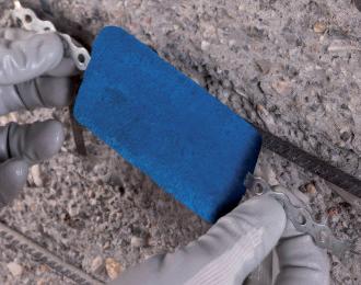
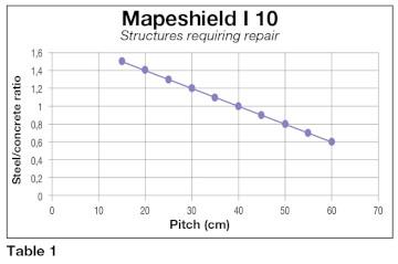
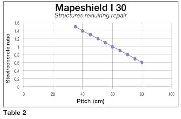
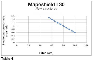
Mapeshield I is made up of a multi-layered zinc core with a large surface area, covered with a special conductive paste which keeps the system active over the years After connecting Mapeshield I to the reinforcement rods with metallic stays, a difference in potential is created between the steel and the zinc which stops corrosion and impedes its formation, even if the surrounding environment is particularly aggressive, for example due to the presence of chlorides In fact, when two different metals are connected together in a suitable electrolyte (in this case the concrete), the metal with the most negative potential (the zinc) will corrode, while the metal with the least negative potential (steel reinforcement rods) remains protected against corrosion Also, the current generated provokes an increase in the pH level which leads to a slow re-alkalisation of the concrete and, if chloride ions are present, pushes them away. The degree of protection depends on the density of the reinforcement in the structure The number of anodes applied varies according to whether the structure is highly reinforced or with only a small amount of reinforcement, or whether the structure is new or an old structure requiring repair. This calculation must be carried out using the attached graphs which indicate the reinforcement/concrete ratio and the pitch between each anode
Mapeshield I is available in two different lengths and 4 different masses so the system may be used in most structures
The surface which the anode is capable of protecting depends on its size (the bigger the anode, the larger the area it protects) while the mass, which is proportional to the amount of metal it contains, effects its duration Mapeshield I ensures that the steel reinforcement is depolarised in compliance with the prescriptions in the EN 12696 European standard “Cathodic protection of steel in concrete” .
RECOMMENDATIONS
Mapeshield I may not be applied where there is structural damage to the reinforcement In such cases, the reinforcement must be integrated or replaced according to calculations carried out by a specialised technician When the use of Mapeshield I is planned, do not apply Mapefer, Mapefer 1K or any other type of anti-rust protection on the reinforcement rods

Do not use epoxy or polyurethane mortar, or mortar reinforced with metal �bres, to carry out repair work
If repair work is required, we recommend the use of a compensated-shrinkage mortar according to UNI EN 1504-3 standards with a maximum resistivity of 100 kΩ*cm
APPLICATION PROCEDURE
Structures which require repairing
Preparation of the substrate
Prepare the substrate by removing the deteriorated and detached concrete, including from below the reinforcement rods, until a solid, strong substrate with a rough surface is obtained. Any areas previously repaired and which are not perfectly bonded must also be removed All corrosion and loose particles must be removed from the reinforcement rods to guarantee that there is good contact between the steel and the repair mortar or concrete The continuity of the reinforcement rods must be checked with an ohmmeter before installing the protection.
How to choose the anode and the pitch required
Three main factors must be considered when choosing the most suitable anode:
· the shape of the structure; the size of the structure;
duration of the passivity of the reinforcement rods to be guaranteed under all conditions, including in the presence of chlorides or cracks
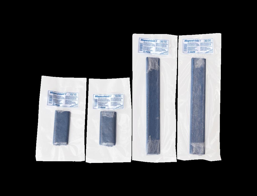
Mapeshield I is available in 4 different con�gurations:
Mapeshield I 10/10
Mapeshield I 10/20
Mapeshield I 30/10
Mapeshield I 30/20
Where the �rst number indicates its length (10 and 30 cm) and the second number its duration (10 and 20 years) according to the structure under repair and the mass of the anode or example, on a heavily-reinforced structure requiring repair (steel/concrete ratio = 0 8-1) with 30 cm long anodes and a service life of 20 years (Mapeshield I 30/20), according to table 2 the number of anodes required to protect the surface is 3 per square metre
Application of the anodes
The anodes must be positioned and fastened �rmly in place to the reinforcement rods so that they do not move during repair and casting operations They must be attached to the reinforcement rods with the metallic fasteners supplied with the anodes using wire or by welding. Enough space must be left under the anodes to allow the mortar to penetrate when repairs are carried out This space must never be less than 2-3 times the size of the largest aggregate in the repair mortar Once installed, the continuity between the anodes and reinforcement rods must be checked with an ohmmeter
Application of the repair mortar
The electrical resistivity of the repair mortar must be in a range of between 50% and 200% of the original concrete and up to a maximum of 100 kΩ, as speci�ed in EN 12696 standards. Mortars from the Mapegrout range comply with the requirements and are therefore recommended for repairing structures protected with galvanic cathodic systems Carry out repairs following normal application guidelines, according to the product chosen and the indications on the data sheet of the mortar used for the repairs. When applying the mortar, do not leave any gaps around the anodes.
New structures
Mapeshield I may be used on new structures even if they are located in particularly aggressive environments If the system is placed on the reinforcement rods, complete passivity is guaranteed Even if the concrete used has been made according to EN 206, UNI 11104 or Eurocodice 2 standards, cracks may appear over the years due to shrinkage following incorrect curing procedures or the continuous external stresses to which it is subject (vibration, dynamic loads, impact etc ) Water, oxygen, carbon dioxide and chlorides may then penetrate into the cracks and corrode the reinforcement rods. A galvanic cathodic protection system installed correctly in the concrete considerably increases the duration of the structure, by delaying problems caused by unforeseen defects for a number of years
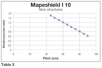
To protect new structures, fewer anodes are required compared with repaired structures and they have a much higher duration This is due to the fact that, on new structures, the reinforcement rods are passive and so the current required to keep them protected is minimal
For example, in a new highly-reinforced structure (steel/concrete ratio = 0 8-1) two Mapeshield I 10/20 anodes every square metre (see table 3) offer protection against corrosion for approximately 40 years, and when the anodes are completely consumed the reinforcement rods will still be passive
Functional checks
In order to check the system, several reference electrodes (in Ag/AgCl for example) must be embedded in the concrete when it is cast or applied in the area protected by the anodes which are to be monitored Several anodes in critical areas are connected to cables with an on/off switch and then connected with the cables from the reference anodes to an external switch box
The procedure for the functional checks is described in the EN 12696 standard which states: depolarisation during the 24 hours after switching off of at least 100 mV compared to the potential measured between 0 1 and 1 second after disconnecting the anode (instant off); depolarisation over a longer period (> 24 hours) of at least 150 mV after instant off Mapeshield I complies with the above criteria
PRECAUTIONS TO BE TAKEN DURING AND AFTER APPLICATION
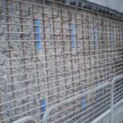
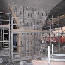
Mapeshield I applied to a viaduct pile under repair
Mapeshield I applied to the reinforcement of a �yover pile
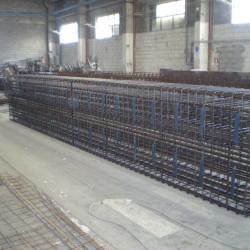
Mapeshield I welded to the reinforcement of a new beam in the construction of a dockyard quay
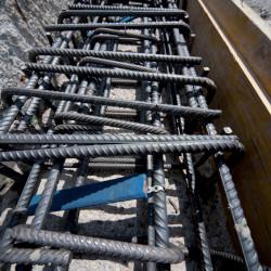
Construction of a new central reservation protected with Mapeshield I
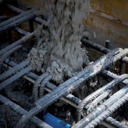
Pouring concrete for a structure protected with Mapeshield I
CONSUMPTION
See attached graphs
PACKAGING
Mapeshield I 30/10 and 30/20 in boxes of 12
Mapeshield I 10/10 and 10/20 in boxes of 24
STORAGE
Mapeshield I may be stored for up to 24 months in its original packaging in a dry place
SAFETY INSTRUCTIONS FOR PREPARATION AND APPLICATION
Mapeshield I is an article and referring to the current European regulations (Reg 1906/2007/CE - REACH) does not require the preparation of the material Safety Data Sheet During use it is recommended to wear protective gloves and goggles and follow the safety requirements of the workplace
PRODUCT FOR PROFESSIONAL USE TECHNICAL DATA (typical values)
special precautions need to be taken if the temperature is between +5°C and +35°C
No
MAPESHIELD I 30 U M 30/10 30/20 External surface mm 300 x 50 ± 5% 300 x 50 ± 5% Height mm 10 ± 10% 12 ± 10% Total weight g 450 ± 10% 570 ± 10% Mass of zinc g 340 ± 2% 450 ± 2% Outside colour – light blue light blue Packaging – vacuum-packed vacuum-packed MAPESHIELD I 10 U M 10/10 10/20 External surface mm 100 x 50 ± 10% 100 x 50 ± 10% Height mm 12 ± 10% 15 ± 10% Total weight g 230 ± 10% 320 ± 10% Mass of zinc g 168 ± 2% 245 ± 2% Outside colour – light blue light blue Packaging – vacuum-packed vacuum-packed
WARNING
Although the technical details and recommendations contained in this product data sheet correspond to the best of our knowledge and experience, all the above information must, in every case, be taken as merely indicative and subject to con�rmation after long-term practical application: for this reason, anyone who intends to use the product must ensure beforehand that it is suitable for the envisaged application: in every case, the user alone is fully responsible for any consequences deriving from the use of the product
Please refer to the current version of the Technical Data Sheet, available from our website www mapei com
LEGAL NOTICE
The contents of this Technical Data Sheet (“TDS”) may be copied into another project-related document, but the resulting document shall not supplement or replace requirements per the TDS in force at the time of the MAPEI product installation
The most up-to-date TDS can be downloaded from our website www.mapei.com.
ANY ALTERATION TO THE WORDING OR REQUIREMENTS CONTAINED OR DERIVED FROM THIS TDS EXCLUDES THE RESPONSIBILITY OF MAPEI
6102-11-2020-gb Any reproduction of texts, photos and illustrations published here is prohibited and subject to prosecution