Installation.
V1.0, 2023
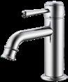
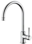
Eternal Basin Mixer
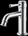
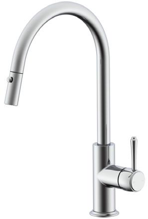
Eternal Gooseneck Basin Mixer
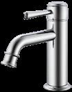
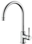
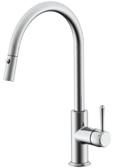
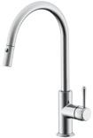
Eternal Sink Mixer
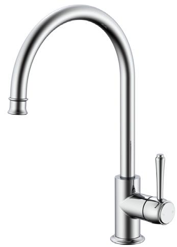
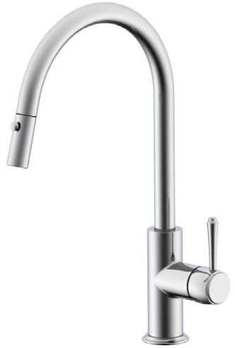
Eternal Pull-Out Sink Mixer
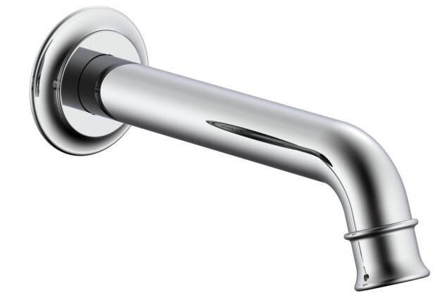
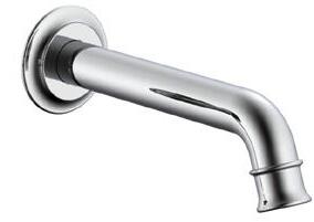
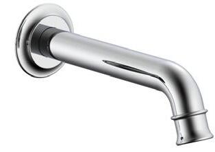
Eternal Wall/Bath Spout
Eternal Wall Top Assembly (pr)
Eternal Wall/Shower Mixer
p.2
p.2
p.4
p.6
p.8
p.9
p.10
Products in this manual must by regulation be installed by licensed and registered trade people.
Water supply requirements
Not recommended for gravity fed water systems or water tanks.
Working Pressure: 350 – 500kpa (including cold and hot water pressure)
Maximum Pressure: 73psi / 500kpa
Temperature Rating: 5°C - 65°C (must not exceed 70°C)
Installation should comply with Australian standard AS/NZS 3500 or relevant local authority requirements.
Eternal Basin Mixer.
Extended Basin Mixer.
Before you start
Clean and flush out water supply pipes before installing any of our products to ensure there is no foreign matter in the pipes that could damage your tapware.
Before product installation, confirm whether the installation space meets the requirements according to the product specification drawings. The installation platform must include a tap hole for the hob fixing of this product. Maximum platform thickness is 35mm. The tap hole required for the fixing of this product must be 33mm – 38mm
1. 2. 3. 4.
Main body installation
UNPACK: Remove the faucet from the packaging, rotate Lock Nut (6) anti-clockwise to remove from Brass Thread (3).
GATHER: Please ensure O-Ring (2), Rubber Washer (4) and Gasket (5) are also removed from Brass Thread (3) and placed in a safe place as they will be required for installation.
SEAT: Ensure the Brass Thread (3) is tightly fastened to the Main Body (1). Insert Main Body (1), Brass Thread (3) and O-Ring (2) into tap hole from the top. Correct the installation angle of the Main Body, most commonly facing the waste hole in the basin, then insert Rubber Washer (4), followed by Gasket (5) onto Brass Thread (3) from the underside of the top.
FASTEN: Fasten Lock Nut (6) onto Brass Thread (3) by turning it clockwise until all components (5), (4) and (2) are tightly locked to the Brass Thread, and the Main Body is firm. This will create a water-tight seal.
Water connection
INSERT: Install Flexible Hoses (7) from the bottom of the Main Body (through centre of Brass Thread) and turn clockwise to hand tighten. Do not overtighten as this may cause the flexible hose to kink and limit or block the water supply or pressure.
CONNECT: Connect the Flexible Hoses to the hot and cold stop valves (water supply) and tighten clockwise with wrench. Ensure faucet lever is the closed position, turn on the hot and cold stop valves to ensure there are no water leaks from the stop valves or the Flexible Hoses.
NOTE: Make sure that the hot and cold Flexible Hoses are connected properly, with the hot on the left, and the cold on the right; when standing in front of the faucet.
Seal test
CLOSED: Turn on the main water and rotate the cartridge in its closed position, between hot and cold connection (anti-clockwise/clockwise), testing the pressure resistance and sealing performance of the pipeline to ensure there are no water leaks.
OPEN: Open the cartridge (up direction), checking for any water leakage from the Main Body and the connections or cartridge. Leaking connections are not covered by the warranty, please check and re-fit accordingly.
LOCK NUT GASKET
RUBBER WASHER
1. 2. 3. 4.
Main body installation
UNPACK: Remove the faucet from the packaging, rotate Lock Nut (6) anti-clockwise to remove from Brass Thread (3).
GATHER: Please ensure O-Ring (2), Rubber Washer (4) and Gasket (5) are also removed from Brass Thread (3) and placed in a safe place as they will be required for installation.
SEAT: Ensure the Brass Thread (3) is tightly fastened to the Main Body (1). Insert Main Body (1), Brass Thread (3) and O-Ring (2) into tap hole from the top. Correct the installation angle of the Main Body, most commonly facing the waste hole in the basin, then insert Rubber Washer (4), followed by Gasket (5) onto Brass Thread (3) from the underside of the top.
FASTEN: Fasten Lock Nut (6) onto Brass Thread (3) by turning it clockwise until all components (5), (4) and (2) are tightly locked to the Brass Thread, and the Main Body is firm. This will create a water-tight seal.
Water connection
INSERT: Install Flexible Hoses (7) from the bottom of the Main Body (through centre of Brass Thread) and turn clockwise to hand tighten. Do not overtighten as this may cause the flexible hose to kink and limit or block the water supply or pressure.
CONNECT: Connect the Flexible Hoses to the hot and cold stop valves (water supply) and tighten clockwise with wrench. Ensure faucet lever is the closed position, turn on the hot and cold stop valves to ensure there are no water leaks from the stop valves or the Flexible Hoses.
NOTE: Make sure that the hot and cold Flexible Hoses are connected properly, with the hot on the left, and the cold on the right; when standing in front of the faucet.
Seal test
CLOSED: Turn on the main water and rotate the cartridge in its closed position, between hot and cold connection (anti-clockwise/clockwise), testing the pressure resistance and sealing performance of the pipeline to ensure there are no water leaks.
OPEN: Open the cartridge (ON direction), checking for any water leakage from the Main Body and the connections or cartridge. Leaking connections are not covered by the warranty, please check and re-fit accordingly.
1.
2.
3. 4. 5.
Main body installation
UNPACK: Remove the faucet from the packaging, rotate Lock Nut (6) anti-clockwise to remove from Brass Thread (3).
SEAT: Ensure the Brass Thread (3) is tightly fastened to the Main Body (1). Insert Main Body (1), Brass Thread (3) and O-Ring (2) into tap hole from the top. Correct the installation angle of the Main Body, most commonly facing the waste hole in the basin, then insert Rubber Washer (4), followed by Gasket (5) onto Brass Thread (3) from the underside of the top.
FASTEN: Fasten Lock Nut (6) onto Brass Thread (3) by turning it clockwise until all components (5), (4) and (2) are tightly locked to the Brass Thread, and the Main Body is firm. This will create a water-tight seal.
Water connection
INSERT: Fasten Check Valve (9) with gasket provided onto extended spout inlet, then attach Extended Spray Hose (8) onto Check Valve (9). Fit supplied Weight onto Extended Spray Hose approx. 200mm from under bench. Check that Pull-Out Spray Nozzle can extend to preference and without interference. Install Flexible Hoses (7) from the bottom of the Main Body. Do not overtighten as this may cause the flexible hose to kink and limit or block the water supply or pressure.
CONNECT: Connect the Flexible Hoses to the hot and cold stop valves (water supply) and tighten clockwise with wrench. Ensure faucet lever is the closed position, turn on the hot and cold stop valves to ensure there are no water leaks from the stop valves or the Flexible Hoses.
NOTE: Make sure that the hot and cold Flexible Hoses are connected properly, with the hot on the left, and the
Seal test
CLOSED: Turn on the main water and rotate the cartridge in its closed position, between hot and cold connection (anti-clockwise/clockwise), testing the pressure resistance and sealing performance of the pipeline to ensure there are no water leaks.
OPEN: Open the cartridge (ON direction), checking for any water leakage from the Main Body and the connections or cartridge. Leaking connections are not covered by the warranty, please check and re-fit accordingly.
Main body installation
PREPARE: Apply proper amount of PFTE TAPE on the threaded wall outlet.
CONNECT: Install Back Plate (2) and O-Ring (1) over Spout (3); allowing suitable working space.
Fasten Spout (3) onto threaded wall outlet by turning clockwise until tight and spout outlet is facing downward and straight.
TRIM: Gently slide Back Plate (2) against finished wall. The rubber O-Ring will keep into place. The rear of the Back Plate can also be fixed with nonacidic silicone or double-sided adhesive.
Wall Top Assembly (pair).
Before you start
It is important to determine the finished wall depth for this product. The embedded depth distance recommended is 38mm - 65mm.
1.
Screw Ceramic Spindle (10) into wall body. Insert Fibre Washer (9) and Spindle Lock Nut (8). Fasten.
Saw off excess thread using Gauge as indicator and file edges.
Remove Gauge and insert Handle Adapter (4) and screw tight (3).
Insert Large O-Ring (7) and screw Lock Flange (6) and Cut-Off Gauge (5) tightly onto Spindle Lock Nut (8).
Insert Handle (2) and fasten with Grub Screw (1) firmly.
Before you start
Clean and flush out water supply pipes before installing any of our products to ensure there is no foreign matter in the pipes that could damage your faucet.
Before product installation, confirm whether the installation space meets the requirements according to the product specification drawings.
It is important to determine the finished wall depth for this product. The embedded depth distance recommended is 38mm - 65mm.
Main body installation
CHECK: Before installation, attach the threaded pipe connectors to the water inlet (5b) and ensure that the water inlet supply is at the same level to the wall.
DEPTH: Ensure that the Main Body (5) is properly secured in the wall, typically on a timber/metal noggin, through the mounting lugs and check that the depth is correct taking the finished wall into consideration.
CONNECT: Apply proper amount of PFTE TAPE on the inlet threaded pipe connector and connect hot and cold water supply (hot on the left, cold on the right, when viewed from operating position), or as marked on Main Body (5).
Seal test
CLOSED: Turn on the main water, carefully remove the Cartridge Sheath (4) and rotate the cartridge in its closed position, between hot and cold connection (anti-clockwise/clockwise), testing the pressure resistance and sealing performance of the pipeline to ensure there are no water leaks.
OPEN: Using a ½” plug, plug the outlet of the Main Body (5a). Open the cartridge (up direction), checking for any water leakage from the Main Body and the connections.
PROTECT: After the Seal Test, please replace the Cartridge Sheath (4) and continue installation if there were no water leaks present. Leaking joints are not covered by the warranty.
Embedding main body
LEVEL: Measure Main Body with parallel ruler to ensure it is perpendicular to the wall.
CLEAR: Ensure there is no rough concrete or tile glue/grout in contact with plated parts of the faucet allowing enough clearance and activity space for the handle wheel to manoeuvre.
CONCEAL: Finish tiles and grout.
Trim installation
FINALISE: After tiling is complete, remove Cartridge Sheath.
TRIM: Install Back Plate (3), adjust to suitable position. The rear of the Back Plate can be fixed with non-acidic silicone or double-sided adhesive.
COMPLETE: Install handle (1) to the cartridge. Fasten Handle using Grub Screw (2) and Allen Key (6).
And thanks for following our instructions and advice. We hope you enjoy your tapware and accessories for many years to come.
Remember just keep it simple and Wipe, Rinse, Dry!