TRIBHUVAN UNIVERSITY

INSTITUTE OF ENGINEERING
INSTITUTE OF ENGINEERING
LAMACHOUR, POKHARA
A Project Report on
“REAL-TIME HUMAN HEALTH MONITORING SYSTEM”
SUBMITTED BY:
Anuj Krishna Phuyal (PAS075BEI005)
Bibek Adhikari (PAS075BEI008)
Prashikshya Baral (PAS075BEI029)
Sabin Subedi (PAS075BEI031)
SUBMITTED TO:
DEPARTMENT OF ELECTRONICS AND COMPUTER ENGINEERING
BAISHAKH, 2079
We owe our deepest gratitude to the Department of Electronics and Computer Engineering,IOE,PaschimanchalCampusfor providinguswithanopportunityto work on a Minor Project as a part of our syllabus. It is an honor for us to express our gratitude to our project supervisor Laxmi Prasad Bastola for providing us all support and guidance during the working phase.
We are thankful to and fortunate enough to get constant support, encouragement, and guidance from all our teachers for their suggestions and lectures that paved towards the completion of this project. Also, we would like to thank our colleagues for their valuable comments and their suggestions during this project. Any kind of suggestion or comment will be highly appreciated and acknowledged.
Real-time health monitoring is very important for people suffering from critical illnesses. The need for this monitoring is even more profound for differently-abled people with such critical illnesses. Lack of proper monitoring and timely response can often lead to the death of such patients.
The project focuses on addressing this need by designing a portable and easy-to-use device that helps measure the vital health parameters of the patient and provides the result through the internet to anyone that is concerned with the patient’s health. The systemisdesignedtomonitorthevitalhealthsignofthepatientandallowthecaretakers to access those readings over the internet. The project aims to use the scope of IoT to enable caretakers to efficiently monitor the differently-abled patients even when they cannot be in direct physical contact with them.
The device allows the user to monitor the health status of the patient in a timely manner and take any actions that are required for their health benefit. We have tried to design the device to make it very easy to use so that even patients with severe physical limitations can use it with little or no assistance.
The internet has become a vital component of daily life in the present age. The services provided by the internet have changed the way in which people carry out their daily activities. These services have enhanced the various sectors from education, transportation, entertainment, health among many others.
The Internet of Things, or IoT, is emerging as the next technology mega trend. Visualizing a world where several objects will sense, communicate and share data over a personal net protocol or public networks can be done through IoT. The interconnected objects collect the data at regular intervals, analyze and initiate needed action, providing associated intelligent networks for analyzing, designing and decision making.
This scope of IOT has been utilized to improve the accessibility and efficiency of health services in many ways. There is a growing number of people suffering from persistent diseases in many developing and under-developed countries. These patients require regular health check-upsandattention ofhealthpersonnelsin ashortperiod oftimeif theirhealthdeteriorates suddenly and rapidly. Chronic diseases are extremely variable in their symptoms, evolution and treatment. Some, if not monitored and treated early, will end the patient’s life. For several years the standard measure of glucose level, pressure level and heart beat was calculated in specialized health centers. Due to technological development, there is a great variety of running sensors giving important signs such as blood pressure cuff, glucometer and pulse monitor together with electrocardiogram, which permits the patient to take their vital signs daily.
By making use of these sensors and IOT, we are capable of accessing the major health parameters of the patients over the internet in real time. With the help of this technology, the doctors, caretakers or relatives can view the vital health readings even when they are not physically present with the patient. Whenever the parameters being checked go beyond the normal limits, the concerned people can immediately provide the assistance required by the patient.Thistechnologycanmaketakingcare ofpatientssufferingfromchronicdiseasesmuch easier and more economical. It is even more useful to help differently-abled patients with chronic conditions.
Differently-abled people always have difficulties when they have to visit the hospitals. The necessity of portable devices that can help these people to get general checkups of vital health parameters has been well-founded for a long time. Most of the technologies providing these services are very expensive that simply puts the technology out of reach for patients in low-income countries.
The major motivation for the project is to help the differently-abled patients to get the health updates from the comfort of their homes and also to help their caretakers to attend to them effectively even when they cannot be physically present with them. The exchange of information regarding vital parameters over the internet also helps to save valuable time incase of any emergenciesthat require urgent actiononthebasis oftheparameterreadings.
In the present scenario, no matter how critical or simple the condition of the patient's life is, they are obliged to go to the hospital. This has not only affected the lives of patients but also of their close ones which include their personal life, work-life, and their economic state. So, we are striving to create an environment where not only the burdens will lessen but also it will make the life of patients and their close ones easier.
The objective of this project is:
● To design a human health monitoring system to facilitate differently abled people utilizing the concept of IoT
● To introduce the use of science and technology in the Health Sectors to increase the efficiency and effectivity of the health sectors in developing country like nepal by using the concept of IoT
Every engineering design is the outcome of the past experiences and observations. It is necessary to justify the result of the analysis and design properly with reference to the preexisting standard results or the past experiences. All the sides have to be taken into consideration for a project basis. The basic objective in a health monitoring system is to provide the basic health measurement like temperature, pulse. For this design, certain references and criteria are taken from the literatures described below.
Jimenez discussed building an ad-hoc extensible monitoring system of patient’s health. They have used low cost sensors and also used existing IOT technology as a platform for establishing communication.
They developed this monitoring system to help elderly people. Their system is mainly on alerting a patient's guardian or the physician if any aged person is in need of medical aid. Also, they performed performance testing if the system is capable of handling multiple requests at a time and also if the number of sensors are increased.
Xican reviewed new advancements in radar sensors design systems that offer low power healthcare, indoor real time positioning and different applications in IOT.
To improve the detection accuracy, detection range and power consumption they have proposed different radar frontend architecture and digital processing methods.
Some of the recent developments are beam forming and duty cycle.
They say that CMOS technologies are used for low power and low cost radar sensors that can be further studied for developing applications using IOT and WSN. They have compared the different radar architectures.
Moosavi implemented two architectures based on IOT for remote monitoring. They developed these two architectures with two different wireless technologies. One is using WI-FI and the other is by using Zig-bee. Their goal is to find the advantages and disadvantages of these systems. In zig-bee, the system contains a different set of sensor nodes. The data is read from different medical sensors and processes it by sending through zigbee to the server.
The WI-FI sensor system accessed the biomedical signals and updated the database in the server.
In both the test cases, the servers collect the data and update the database. This database can be accessed and displayed in a web page for remote access.
Requirement analysis encompasses those tasks that go into determining the needs and conditions to meet for a new or altered product, taking account of the possibly conflicting requirements of the various stakeholders, analyzing, documenting, validating and managing the system.
A functional requirement is a system's key prerequisite that explains the system's behavior under certain parameters and specifies what the system must perform. The following are some functional requirements that are similar to our project:
● User Interface and Login: The system will be used by a variety of users, including patients, doctors, drivers, and health care professionals. Various users will have different login procedures.
● Update patient data: This system is essential when a new patient joins the system or when doctors wish to record data about a patient.
● Database management system: It ensures data integrity and allows information to move across departments. It serves as the master data record for all of the patient's participation history and keeps them safe because only authorized individuals can access it.
● Network Access: Allow users to access the program over Wi-Fi or cellular data.
A non-functional requirement, on the other hand, is a chosen requirement that outlines how thesystemwillfunction.Non-functionalneedsaregivenlessconsiderationin every project than functional ones. Some of the non functional requirements are:
● Flexibility and Performance: Considering it will be used by people of various abilities, the system should be versatile and simple to use. It should be quick and accessible to a big number of people in terms of performance.
● Portability: It may be accessible via mobile, desktop, laptop, and other devices.
● Availability: Because emergency events can occur at any moment, the system should be operational 24 hours a day, seven days a week.
The main purpose of our project is to provide an efficient health monitoring approach to the specially abled persons introducing the concept of the I.O.T, where we use various electronic devices and customized them in such a way that it can work to transfer information from physical device to the web where anyone can read the data obtained and can perform the required suitable actions based on the data obtained.
The various components used in the device and their function are described below:
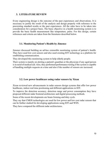
The DS18B20 temperature sensor is used in the device to take the body temperature input ofthe patient.It is acommonly used single-wirethermometer device thatcan be held inside the palm or any other body part to measure the temperature. DS18B20 is a digital thermometer that can measure the temperature between -55OC ( -67OF) to 125OC (257OF).
The DS18B20 digital thermometer provides 9-bit to 12-bit Celsius temperature measurements and has an alarm function with nonvolatile user-programmable upper and lower trigger points. The DS18B20 communicates over a 1-Wire bus that by definition requires only one data line (and ground) for communication with a central microprocessor. In addition, the DS18B20 can derive power directly from the data line (“parasite power”), eliminating the need for an external power supply.
Pin Configuration:
No: Pin Name Description
1. Ground Connects to the ground of the circuit
2. VCC Powers the sensor; can be 3.3V or 5V
3. Data This pin gives the output the temperature value which can be read using a one-wire method.
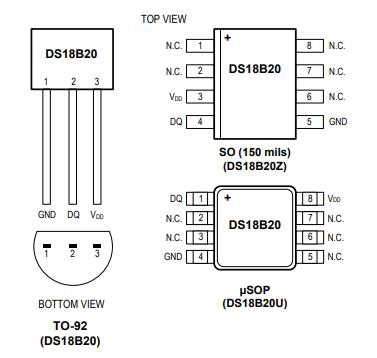
An analog heart rate pulse sensor is used to take the heart rate of the patient. The plug-andplay type heart rate sensor can either be clipped in between two fingertips or in the earlobe. The sensor contains ambient light sensor, a led and a square shaped noise cancellation circuitry in its front view whereas all the electronic components are mounted on the back view of the sensor.
It works on the principle of the light modulation by blood flow through fingers where the duration between the blood in veins is detected by the ambient light sensor which gives the pulse rate of the human body. There is a difference in the reflection of light when there is blood in veins and when there is not. The difference is analyzed and human heartbeat is determined and the value is then passed on to the node mcu.
The sensor has three legs. One each for ground connection, power supply and the heart rate output generated by the sensor.
The heartbeat sensor contains three pins discussed below:
Pin No: Pin Name Description
1. Ground It is connected to the ground terminal of the system.
2. VCC It is connected to the supply voltage.
3. Signal It is connected to the pulsating output signal.
The ESP8266 NodeMCU CP2102 board has ESP8266 which is a highly integrated chip designed for the needs of a new connected world. It offers a complete and self-contained Wi-Fi networking solution, allowing it to either host the application or to offload all Wi-Fi networking functions from other application processors.
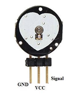
In our project the NodeMCU is particularly suitable since it provides a built-in Wi-Fi module and allows us to feed the data collected from the sensors to the node server in real time.
The ESP 8266, 12 E Node MCU has a total of 30 pins. Among these 14 pins are active. It also has an onboard flash or reset button, 3.3V voltage regulator, Micro USB, etc.
It has around 17 GPIO pins but only 13 are brought out to outside for the external connection. Other pins are connected internally for the processor and other peripheral interfacings. Also, you can see this board has a total of 8 power supply pins among which 3 nos 3.3V power out pins, 3 nos grounding pins, and 1 no 5V Vin or Power In pin. The GPI0 is connected to the flash button. So it can be flashed or reset by the flash button or by the external signal through the GPI0 Pin.
Pin Category Name Description
Power Micro-USB, 3.3V, GND, Vin Micro-USB: Used to power the node mcu.
3.3V: Regulated input power GND: Ground pin. Vin: External power supply.
Control Pins EN, RST The pin and the button resets the microcontroller.
Analog Pin ADC0 Used to measure analog voltage in the range 0-3.3V.
GPIO Pins GPIO 1 -GPIO 16 General purpose input-output pins.
SPI Pins CLK, SD1, CMD, SD0 Pins used for SPI communication.
UART Pins TXD0, RXD0 TXD1, RXD1
I2C Pins
NodeMCU has two UART interfaces, UART0 and UART1. UART1 is used to upload to the firmware/program.
The NodeMCU has I2C functionality support.
Here, to set up the proper health monitoring system the sensors that take the inputs of pulse and temperature taking sensors are interfaced with the NodeMCU. The temperature provides the temperature output in digital form whereas the heartbeat sensor working on the principle of light modulation produces an analog output which is fed to the NodeMCU The inbuilt ADC function of the node mcu converts the analog signals from the pulse sensor to digital form.
The node is programmed in such a way that it manipulates the information according to the user’s needs. For this system, the NodeMCU is programmed to determine the blood oxygen level of the patient based on the data obtained from the two sensors. The blood oxygen level is also a vital health parameter that has to be monitored to ensure the wellbeing of the patient. After proper manipulation of the data, the node mcu has to transfer the obtained data to the cloud.
The built-in Wi-Fi module helps to upload the data in the node in the cloud. The Wi-Fi module uploads the data into the cloud server. The data is stored in the cloud database and also is viewed in the observer’s web device. The transfer of data happens in real-time so as to provide the readings instantaneously. For this, it is essential that the Wi-Fi module upload the data in real time. The sensors continuously read the data and fetch the data of each instant to the NodeMCU. If the data is not uploaded in each instant, the changes of data in the node may cause false data to be transmitted. This might provide misinformation to the observers which can cause undesired consequences. So the node mcu has to upload the data present in the microcontroller in each instant so that the data being viewed by the observer is correct in each instant of parameter sampling.
In the output interface, the observers can view data in real-time and also access the past data from the database for any particular patient. The database is responsible for continuouslyfetchingthedatatotheserverwhichthenprovidesthedatatothedevicebeing used to view the data. The real-time output interface is designed in such a way that it continuously refreshes the parameter readings.
The functionality of the system depends upon the proper interconnection between the various components of the system. The various components depend upon each other to be able to fulfill each of their individual tasks. Thus, the overall performance is dictated by the interaction between these components. The interrelationships between these components are described below with the help of general block diagrams and UML diagrams.
Send calculated values as post request to next receiving server
Shows the real time data to the
The above block diagram shows the interaction between various components involved in the system. The data originates in the heartbeat sensor and the temperature sensor which is processed by the microcontroller. The calculated values are sent as a post request to the receiving server. The receiving server receives the post request and accepts the data. The accepted data is shown in the observer’s device in real time and at the same time the data is stored in the database along with the timestamp of each instant.


The system can also provide functionality to view the patient’s history. This is achieved by accessing the stored data from the database. Upon receiving the request from the user device the required data is fetched from the database and is presented in the format appropriated by the system software. Furthermore, the available data from the database can be printed as hardcopy if need be.

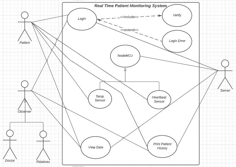
The above shown Use-case diagram of the system is useful to understand the various functions that the system performs along with the actors that can trigger them.
The patient, doctor, relatives or other observers are the primary actors that initiate the functionality of the system. The server simply responds to the various requests as a secondary actor. The patient is responsible to provide the inputs via the sensors which are processed and stored in the server’s database. Any observer has to login to the system’s output interface before they can view the real-time data or the patient’s history from the database. The viewing and printing of the data is assisted by the secondary actor of the system.
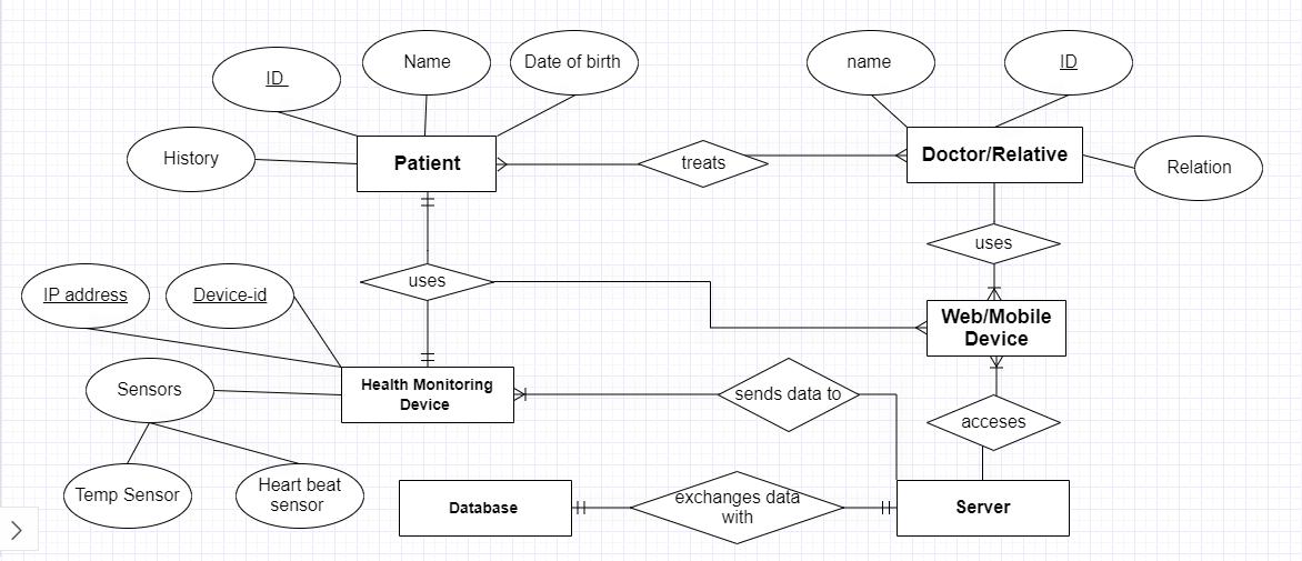
The various entities involved in the system’s operation are interrelated with each other in various relationships. The Entity-Relationship diagram, or the ER diagram shows this interrelationship and dependencies among the entities.
Each entity has its own set of attributes corresponding to it. In the figure, the entities are depicted in the rectangular containers and the attributes of those entities are shown in eclipses. The attributes used for each entity can vary in each individual usage of the system.
Unlike the attributes, the relationship between entities are rigid and cannot be changed foreachusage.Therelationshipsareshowninthediamondcontainers.Thelinesjoining the interrelated entities show the multiplicity of the depicted relation. For example; the patient and the doctor are related in many-to-many relationship, i.e. many doctors can treat many patients, and the patient and the health monitoring device are connected by one-to-one relationship, i.e. one patient is supposed to use one device belonging to him/her. The connecting lines show these varying relationships that can be, one-to-one, one-to-many or many-to many relationships.
The ER diagram is useful to understand the direct dependencies among each of the components comprising the designed system.
We have used the Django development environment for the development of software for the device. Since Django is written in Python code, the setting up of the environment consisted of installing and setting up Python, Django, and a Database System. Since Django deals with web applications, we also needed a web server setup as well.
The major codes for the system’s software are designed in python language. The use of python programming language has enhanced the code readability of the software. As the language puts emphasis on the use of significant indentation, the code is understandable with its functionality clearly outlined within the codes. The manipulation of the data in the NodeMCU happens with the code provided in this language.
But the major objective of our project is to obtain the fetch data from a web server in realtime. So, only the use of a python based program was not sufficient. The real-time data fetching was achieved by the use of Ajax web development technique. The Asynchronous Javascript and XML, abbreviated as Ajax, is a set of web development techniques that uses various techniques in the client-side to create asynchronous web applications. Since the Ajax technology allows to send or receive data from a server asynchronously (in the background) without interfering with the display or the behavior of the existing page, it is possible to change the contents of the web page dynamically without having to reload the entirepage.Thismakes thewebinterface more user-friendlyand the systemmoreefficient.
The database of the designed system is managed with the help of SQL or Structured Query language. This relational database language allows us to extract a series of records with selection, sporting and computational criteria from the data table. The need to create, update or delete data relating to the system is also performed with this query language.
The output of the readings can be observed remotely over the internet in any electronic device by logging on to a specified IP address. The major objective of the project is to allow the caretakers or the health personnel involved with the patient to access the patient’s condition from a remote location. The output interface provides the viewer with information about vital parameters and the presence of a database allows the caretakers to observe the change in those parameters over time and generate useful deductions that can be used for taking decisions to benefit the patient.
The real time output interface allows the observer to view three of the patient’s key health parameters; Body Temperature, Heart Beat Rate and Oxygen Level in the blood. The observer who can either be the patient’s caretaker or the patient themselves can use any device to access the web and view the web page.
The readings of the temperature and heart rate is directly achieved from the server as provided by the node mcu whereas the oxygen level is calculated by the software on the basis of the aforementioned parameters. The temperature is presented in the Degree Fahrenheit unit, heart rate in terms of bpm(beats per minute) and the oxygen level in terms of percentage.
The data shown on the output interface is asynchronously accessed from the server and the change in the data is dynamically displayed in the web page. The observer logs on to a predetermined IP address corresponding to a specific health monitoring device where they are asked to provide their login credentials. Once entered and verified, the viewer is able to see the real-time temperature, heartbeat and the blood oxygen level of the patient.
As mentioned earlier, the temperature and the heartbeat reading is directly obtained from the sensors. Unlike these two readings, the blood oxygen level is a derived quantity that is based on the pulse rate and the body temperature of the patient. These vital health signs are interrelated to each other in any person’s body and thus can change simultaneously with change in any one of the parameters. The general values of these parameters are considered and the software is designed in such a way that the value of the blood oxygen level is determined by a series of comparisons between the values of heart rate and body temperature.
The table presented below is used as the reference by the software while calculating the oxygen level from pulse rate and temperature:
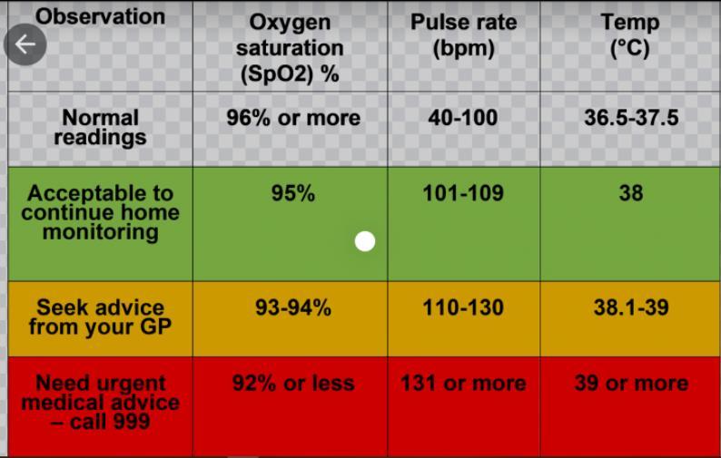
The use of the database allows for a broad assessment of the readings that are taken by the device over a long period of time. A database is maintained to keep record of the readings of parameters and make use of them in future context if required.
The observer is able to access the database of the parameters for any specific patient in a tabular form. Data for each instant is available with its timestamp which allows to observe the trend of change in the health parameters being checked. Also, the system provides a functionality to allow the observers to print the data from the database. The print functionality is essential to allow the doctors or health professionals to obtain health readings of certain significant time spans in hard-copy form and take decisions in benefit of the patient.
A properly maintained database is vital for this system because the device is meant for the use of people with chronic medical illnesses. For such patients, the health parameters of one time instant is not enough to generate a complete assessment of the patient’s health condition. Thus a database is required to determine the trend in which the parameters are changing over a specified period of time.
The analysis of the data in the database is most important to examine the effects of medications provided to the patients and thus to determine if the medical actions taken for the patients are providing expected results or not. Database allows the doctors to understand the patient’s condition more thoroughly and take proper decisions regarding medications and other medical procedures if required. A properly arranged database containing large data from different patients can also be raw data that can be used for broader research purposes.
There are certain exceptions to be considered when the patients or the health workers make use of the system that has been developed. It should be understood that the device focuses mainly on the examination of the health of differently-abled people with chronic conditions. So the usage of the device for other people might generate outputs that may not be consistent with the real values of the vital signs of such users.
The device does not use a separate sensor to measure the oxygen level in the patient’s blood. It has been mentioned that the Oxygen Level is calculated from the temperature and heart rate. So, the reading obtained for the blood oxygen level will be correct in most of the general conditions but may be incorrect for certain specific patients. If any person is a patient of some form of medical condition that affects the blood oxygen level without causing substantial disturbance in the body temperature or heart rate, then the device may show the oxygen level that will be different from the real value. It will not be wise to use this device for such patients as the readings might lead to false assessment of their health and cause unfortunate consequences.
Also the use of this device to measure the vital signs of athletes, heavy load workers or other similar people is not advisable. For such people the values of temperature and heart rate might depend on several other factors that cannot be evaluated under the scope of the prepared device.
Other several exceptions might arise that can be specific to individual patients. Such exceptions should be assessed and reasonably considered by the doctors and caretakers for the patients.
The device designed to fulfill the specified objectives was able to carry out the intended functionality with appreciable accuracy. We were able to obtain the readings of heart beat and temperature and observe the data over the internet in real time. The major objective of making the use of the internet to view the data was successfully conducted.
The device that has been designed and prepared for this project has great potential to help the differently-abled people and their caretakers by allowing the basic health check-up facilities in their home with greatest of ease. The use of the Internet has opened the possibilities for involvement of any number of relatives, caretakers or health professionals at any given time. Patients will have higher chances of getting medical attention at the earliest hours whenever it is required. It should also be noted that the device is simple to use and is designed with a minimum number of components such that patients with severe limitations in physical movements may be able to operate with little to no support from others.
Even after successfully carrying out aforementioned functionalities, this device is not itself a complete product. There are numerous possibilities that can be explored to increase the scopeofuseforthedevicethathasbeen prepared.Increasingthe functionalityof thedevice by adding more sensors and increasing the accuracy of the system by using better sensors are the most basic activities that can be carried out to make the product better. Also, different functionalities can be added in the program itself to make better sense of the obtained data of health parameters.
It is also necessary to improve the security of the software and the internet channel, to make sure that the patients using the services will not lose the integrity of their private information. The database management can be improved to make it more readable and easy-to-follow. Over the long term, it can be essential to add features that can analyze data from various devices corresponding to different patients and determine if anyone requires
the attention of the healthcare professionals and allocate the required resources with minimal human intervention.
[1] A. Bansal, S. Kumar, A. Bajpai et al., “Remote health monitoring system for detecting cardiac disorders,” IET Systems Biology, vol. 9, no. 6, pp. 309–314, 2015.
[2] R. E. Nappi, E. Martini, L. Cucinella et al., “Addressing vulvovaginal atrophy (VVA)/genitourinary syndrome of menopause (GSM) for healthy aging in women,” Frontiers in Endocrinology, vol. 10, p. 561, 2019.
[3] M. M. Islam, A. Rahaman, and M. R. Islam, “Development of smart healthcare monitoring system in IoT environment,” SN Computer Science, vol. 1, no. 3, 2020.
[4] A. M. Koya and P. P. Deepthi, “Plug and play self-configurable IoT gateway node for telemonitoring of ECG,” Computers in biology and medicine., vol. 112, p. 103359, 2019.
Websites:
Google, www.etechnog.com , www.components101.com www.irjet.com


