7 minute read
4. REQUIREMENT ANALYSIS


Requirement analysis encompasses those tasks that go into determining the needs and conditions to meet for a new or altered product, taking account of the possibly conflicting requirements of the various stakeholders, analyzing, documenting, validating and managing the system.
4.1. Functional Requirements :
Advertisement
A functional requirement is a system's key prerequisite that explains the system's behavior under certain parameters and specifies what the system must perform. The following are some functional requirements that are similar to our project:
● User Interface and Login: The system will be used by a variety of users, including patients, doctors, drivers, and health care professionals. Various users will have different login procedures.
● Update patient data: This system is essential when a new patient joins the system or when doctors wish to record data about a patient.
● Database management system: It ensures data integrity and allows information to move across departments. It serves as the master data record for all of the patient's participation history and keeps them safe because only authorized individuals can access it.
● Network Access: Allow users to access the program over Wi-Fi or cellular data.
4.2. Non Functional Requirements:
A non-functional requirement, on the other hand, is a chosen requirement that outlines how thesystemwillfunction.Non-functionalneedsaregivenlessconsiderationin every project than functional ones. Some of the non functional requirements are:
● Flexibility and Performance: Considering it will be used by people of various abilities, the system should be versatile and simple to use. It should be quick and accessible to a big number of people in terms of performance.
● Portability: It may be accessible via mobile, desktop, laptop, and other devices.
● Availability: Because emergency events can occur at any moment, the system should be operational 24 hours a day, seven days a week.
5. METHODOLOGY
The main purpose of our project is to provide an efficient health monitoring approach to the specially abled persons introducing the concept of the I.O.T, where we use various electronic devices and customized them in such a way that it can work to transfer information from physical device to the web where anyone can read the data obtained and can perform the required suitable actions based on the data obtained.
The various components used in the device and their function are described below:
5.1. Temperature Sensor
The DS18B20 temperature sensor is used in the device to take the body temperature input ofthe patient.It is acommonly used single-wirethermometer device thatcan be held inside the palm or any other body part to measure the temperature. DS18B20 is a digital thermometer that can measure the temperature between -55OC ( -67OF) to 125OC (257OF).
The DS18B20 digital thermometer provides 9-bit to 12-bit Celsius temperature measurements and has an alarm function with nonvolatile user-programmable upper and lower trigger points. The DS18B20 communicates over a 1-Wire bus that by definition requires only one data line (and ground) for communication with a central microprocessor. In addition, the DS18B20 can derive power directly from the data line (“parasite power”), eliminating the need for an external power supply.

Pin Configuration:
No: Pin Name Description
1. Ground Connects to the ground of the circuit
2. VCC Powers the sensor; can be 3.3V or 5V
3. Data This pin gives the output the temperature value which can be read using a one-wire method.
An analog heart rate pulse sensor is used to take the heart rate of the patient. The plug-andplay type heart rate sensor can either be clipped in between two fingertips or in the earlobe. The sensor contains ambient light sensor, a led and a square shaped noise cancellation circuitry in its front view whereas all the electronic components are mounted on the back view of the sensor.
It works on the principle of the light modulation by blood flow through fingers where the duration between the blood in veins is detected by the ambient light sensor which gives the pulse rate of the human body. There is a difference in the reflection of light when there is blood in veins and when there is not. The difference is analyzed and human heartbeat is determined and the value is then passed on to the node mcu.
The sensor has three legs. One each for ground connection, power supply and the heart rate output generated by the sensor.
The heartbeat sensor contains three pins discussed below:
Pin No: Pin Name Description
1. Ground It is connected to the ground terminal of the system.
2. VCC It is connected to the supply voltage.
3. Signal It is connected to the pulsating output signal.
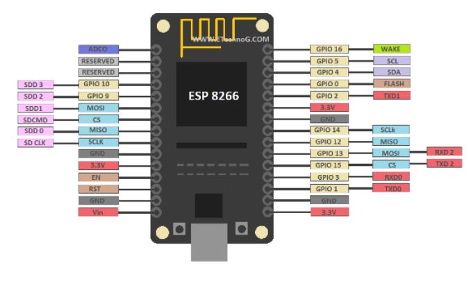
The ESP8266 NodeMCU CP2102 board has ESP8266 which is a highly integrated chip designed for the needs of a new connected world. It offers a complete and self-contained Wi-Fi networking solution, allowing it to either host the application or to offload all Wi-Fi networking functions from other application processors.

In our project the NodeMCU is particularly suitable since it provides a built-in Wi-Fi module and allows us to feed the data collected from the sensors to the node server in real time.
The ESP 8266, 12 E Node MCU has a total of 30 pins. Among these 14 pins are active. It also has an onboard flash or reset button, 3.3V voltage regulator, Micro USB, etc.
It has around 17 GPIO pins but only 13 are brought out to outside for the external connection. Other pins are connected internally for the processor and other peripheral interfacings. Also, you can see this board has a total of 8 power supply pins among which 3 nos 3.3V power out pins, 3 nos grounding pins, and 1 no 5V Vin or Power In pin. The GPI0 is connected to the flash button. So it can be flashed or reset by the flash button or by the external signal through the GPI0 Pin.
Pin Category Name Description
Power Micro-USB, 3.3V, GND, Vin Micro-USB: Used to power the node mcu.
3.3V: Regulated input power GND: Ground pin. Vin: External power supply.
Control Pins EN, RST The pin and the button resets the microcontroller.
Analog Pin ADC0 Used to measure analog voltage in the range 0-3.3V.
GPIO Pins GPIO 1 -GPIO 16 General purpose input-output pins.
SPI Pins CLK, SD1, CMD, SD0 Pins used for SPI communication.
UART Pins TXD0, RXD0 TXD1, RXD1
I2C Pins
NodeMCU has two UART interfaces, UART0 and UART1. UART1 is used to upload to the firmware/program.
The NodeMCU has I2C functionality support.
5.4. Interfacing and Working
Here, to set up the proper health monitoring system the sensors that take the inputs of pulse and temperature taking sensors are interfaced with the NodeMCU. The temperature provides the temperature output in digital form whereas the heartbeat sensor working on the principle of light modulation produces an analog output which is fed to the NodeMCU The inbuilt ADC function of the node mcu converts the analog signals from the pulse sensor to digital form.
The node is programmed in such a way that it manipulates the information according to the user’s needs. For this system, the NodeMCU is programmed to determine the blood oxygen level of the patient based on the data obtained from the two sensors. The blood oxygen level is also a vital health parameter that has to be monitored to ensure the wellbeing of the patient. After proper manipulation of the data, the node mcu has to transfer the obtained data to the cloud.
The built-in Wi-Fi module helps to upload the data in the node in the cloud. The Wi-Fi module uploads the data into the cloud server. The data is stored in the cloud database and also is viewed in the observer’s web device. The transfer of data happens in real-time so as to provide the readings instantaneously. For this, it is essential that the Wi-Fi module upload the data in real time. The sensors continuously read the data and fetch the data of each instant to the NodeMCU. If the data is not uploaded in each instant, the changes of data in the node may cause false data to be transmitted. This might provide misinformation to the observers which can cause undesired consequences. So the node mcu has to upload the data present in the microcontroller in each instant so that the data being viewed by the observer is correct in each instant of parameter sampling.
In the output interface, the observers can view data in real-time and also access the past data from the database for any particular patient. The database is responsible for continuouslyfetchingthedatatotheserverwhichthenprovidesthedatatothedevicebeing used to view the data. The real-time output interface is designed in such a way that it continuously refreshes the parameter readings.
The functionality of the system depends upon the proper interconnection between the various components of the system. The various components depend upon each other to be able to fulfill each of their individual tasks. Thus, the overall performance is dictated by the interaction between these components. The interrelationships between these components are described below with the help of general block diagrams and UML diagrams.
Send calculated values as post request to next receiving server
Shows the real time data to the
The above block diagram shows the interaction between various components involved in the system. The data originates in the heartbeat sensor and the temperature sensor which is processed by the microcontroller. The calculated values are sent as a post request to the receiving server. The receiving server receives the post request and accepts the data. The accepted data is shown in the observer’s device in real time and at the same time the data is stored in the database along with the timestamp of each instant.


The system can also provide functionality to view the patient’s history. This is achieved by accessing the stored data from the database. Upon receiving the request from the user device the required data is fetched from the database and is presented in the format appropriated by the system software. Furthermore, the available data from the database can be printed as hardcopy if need be.
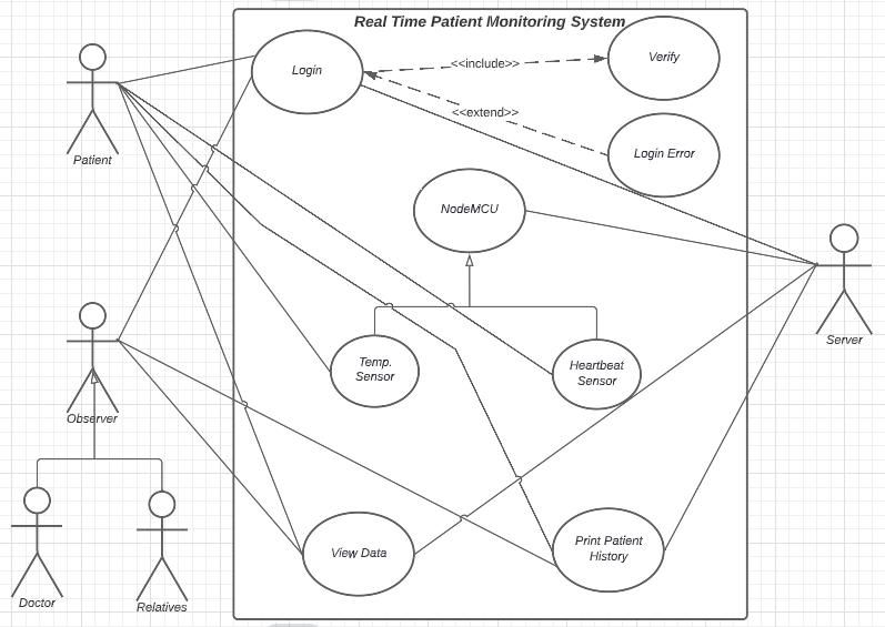
The above shown Use-case diagram of the system is useful to understand the various functions that the system performs along with the actors that can trigger them.
The patient, doctor, relatives or other observers are the primary actors that initiate the functionality of the system. The server simply responds to the various requests as a secondary actor. The patient is responsible to provide the inputs via the sensors which are processed and stored in the server’s database. Any observer has to login to the system’s output interface before they can view the real-time data or the patient’s history from the database. The viewing and printing of the data is assisted by the secondary actor of the system.