
Research and Development of FUROBOT
In the current digital environment, there is a trend towards combining human intelligence with new tools, such as construction robots, to form a new relationship. Designers no longer focus solely on designing appearances, but on creating various parameter logic. As a node-based programming software that builds upon Grasshopper, FUROBOT inherits the parameterized control mode of Grasshopper. In this mode, most parameters are transferred in the form of node input and output, rather than through traditional dialog input.
Parameter Representation
When first learning about FUROBOT, it is important to have a solid understanding of several basic robotics parameter concepts.[3,4] Of all the concepts that require clarification, those listed in Table 1 should be understood first.
Parameter
Tool head center point plane (TCP)
Robot root (Root)
Work object (Work base)
Tool (Tool)
Description
Pose transformation of the moving target of the robot relative to the working base coordinates
The position of the robot’s position relative to the pose of the world system
Pose transformation of robot work object coordinate system relative to robot root coordinate system
Pose transformation of the end of the robot tool head relative to the center point of the flange

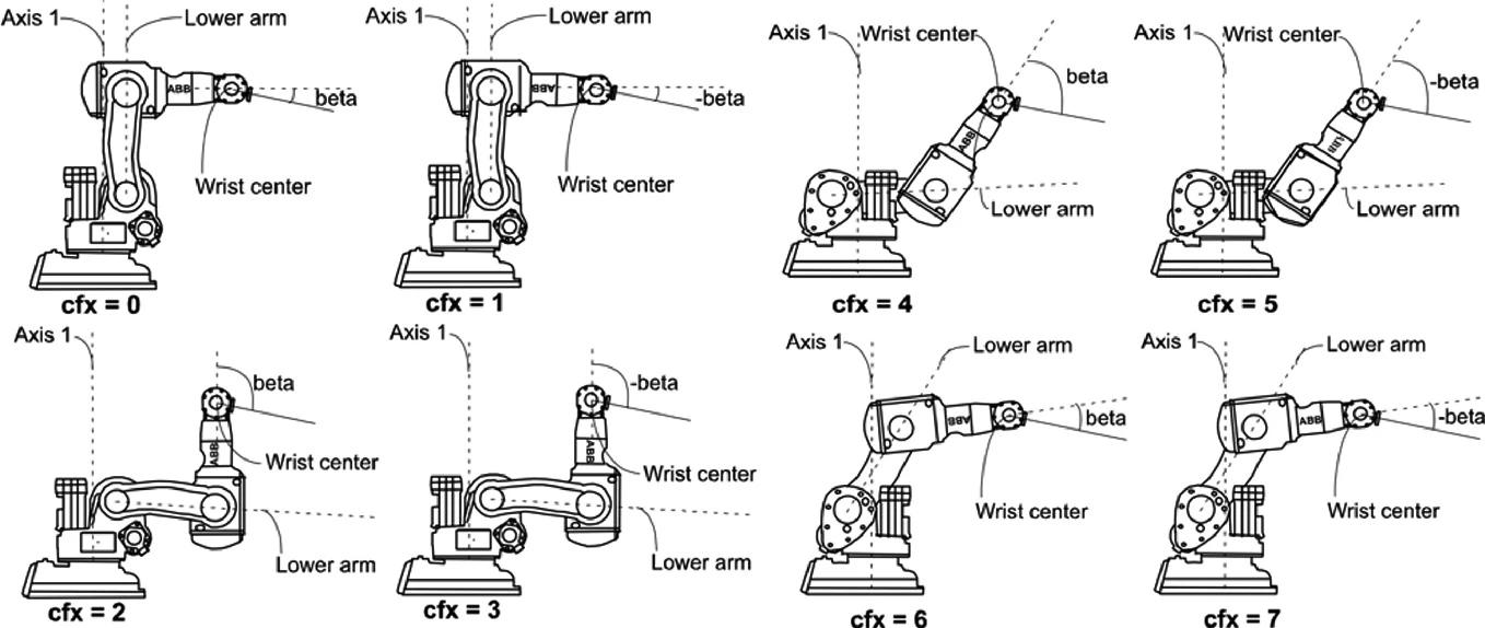
Table 1 Different representation of rotation
Figure 2
Conversion of different rotation representation
Figure 3
General 6D robot has 8 pose states
FUROBOT, which is designed to support the work of multiple robots at the same time, needs to deal with these different pose expressions in a unified manner and provide tools for converting them (Figure 2)
In a normal working space, the 6-axis robot commonly used in the industry has eight pose states to choose from for reaching the center point plane (TCP) of the same tool head (Figure 3). While the UR robot does not have explicit pose state parameters for users to select, its pose state parameters are implicitly derived from the previous state of the robot. Thus, only the preset robots KUKA and ABB require manual selection of pose state parameters.
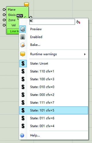
To ensure consistency across different types of robots, it is necessary for FUROBOT to use a standardized parameter format for pose parameters. To this end, the software platform adopts the official parameters designated by KUKA as the reference and maps the corresponding parameters of ABB and UR robots one-to-one according to this reference (Table 2). Additionally, motion command options corresponding to these pose parameters are available in the input interface of FUROBOT (Figure 4)
2 ABB and KUKA pose state conversion
Workflow
The technological revolution triggered by digital technology has brought about fundamental changes in architectural design. Thinking, design, and construction have become organically integrated in
ORO Editions
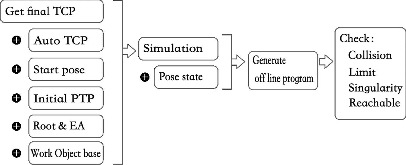
Figure 4
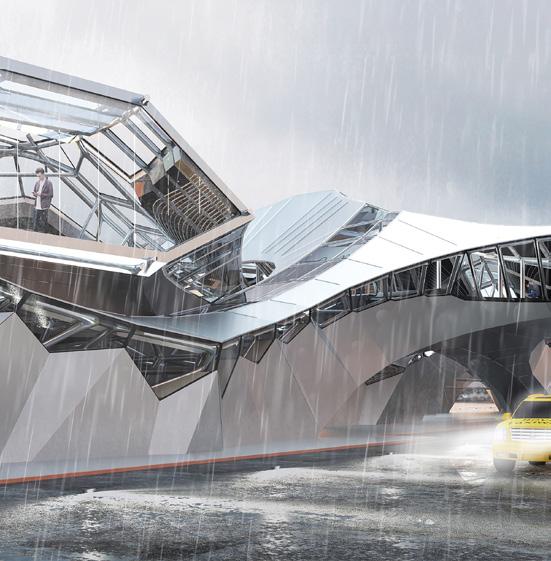

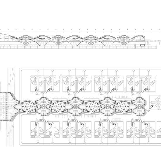
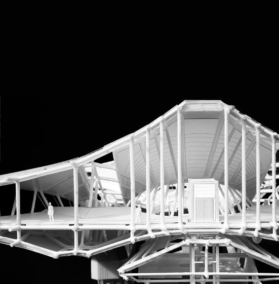
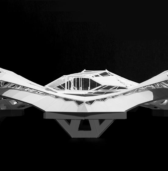
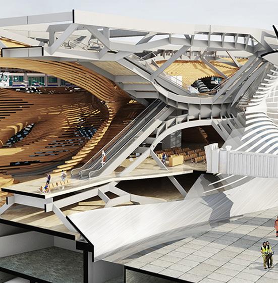
Figure 15 (above left)
A side view of the boarding gate and the interweaving structural geometry of the terminal.
Project credit: Tian Ouyang and Jasmine Gao.
Figure 16 (above middle)
Sectional perspective of the terminal showing the boarding gate on the top and the circulation of passengers and cargo transport through the terminal. Project credit: Tian Ouyang and Jasmine Gao.
Figure 17 (above right)
The plan and section of the interweaving terminal. Project credit: Tian Ouyang and Jasmine Gao.
Figure 18 (below left)
A view of the physical scale model of the terminal showing how the interweaving parts only share the circulation core with each other. Project credit: Tian Ouyang and Jasmine Gao.
Figure 19 (below middle)
Another view of the terminal model representing the integration of structural and architectural geometry. Project credit: Tian Ouyang and Jasmine Gao.
ORO Editions
Figure 20 (below right)
Sectional perspective view of the terminal revealing the structural system and architectural components of the interior as well as the facade of the terminal. Project credit: June Zhu, Linnan Yu,and Yiwei Gao.
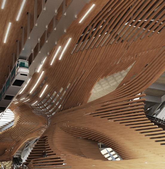
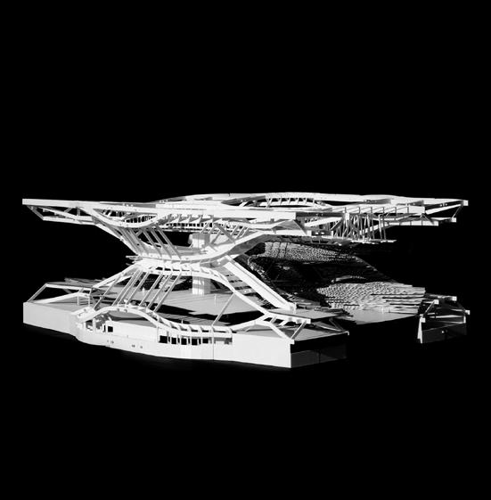
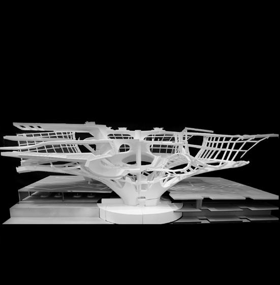
Figure 21 (above left)
Interior view of the terminal with the gates on the top floor, at which the passengers can directly arrive via the air train suspended from the ceiling of the terminal. Project credit: June Zhu, Linnan Yu,and Yiwei Gao.
Figure 22 (above middle)
A sectional perspective of the terminal representing various modes of transportation and architectural space within the terminal. Project credit: Zehua Qi and Qi Liu.
Figure 23 (above right)
Another structural model of a terminal where the internal space is designed as a multi-story spaces to receive drones on the top and conventional airplanes on the side. Project credit: Zhou Xieyang and Duan Xiaoyu.
Yuhan Bao
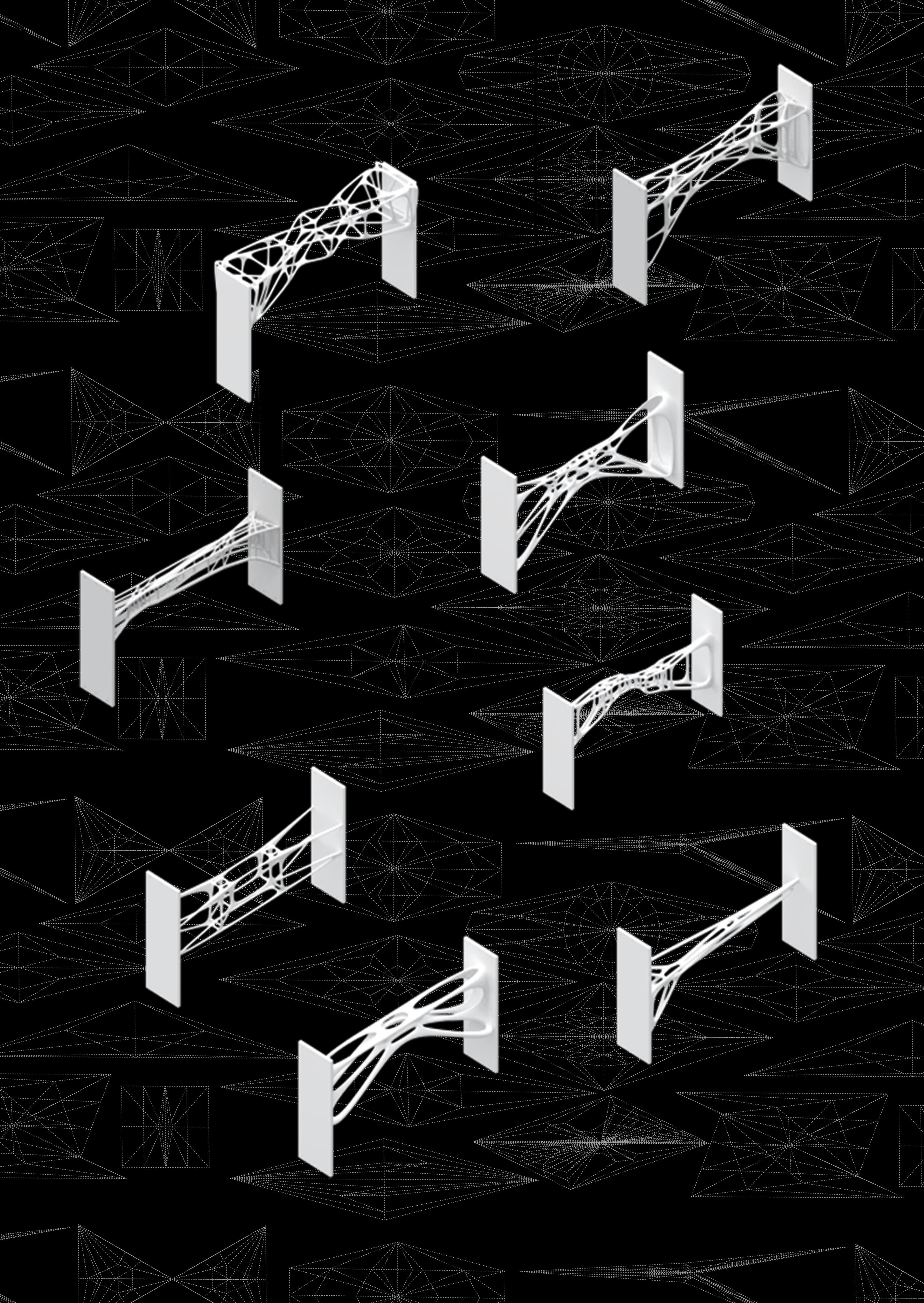
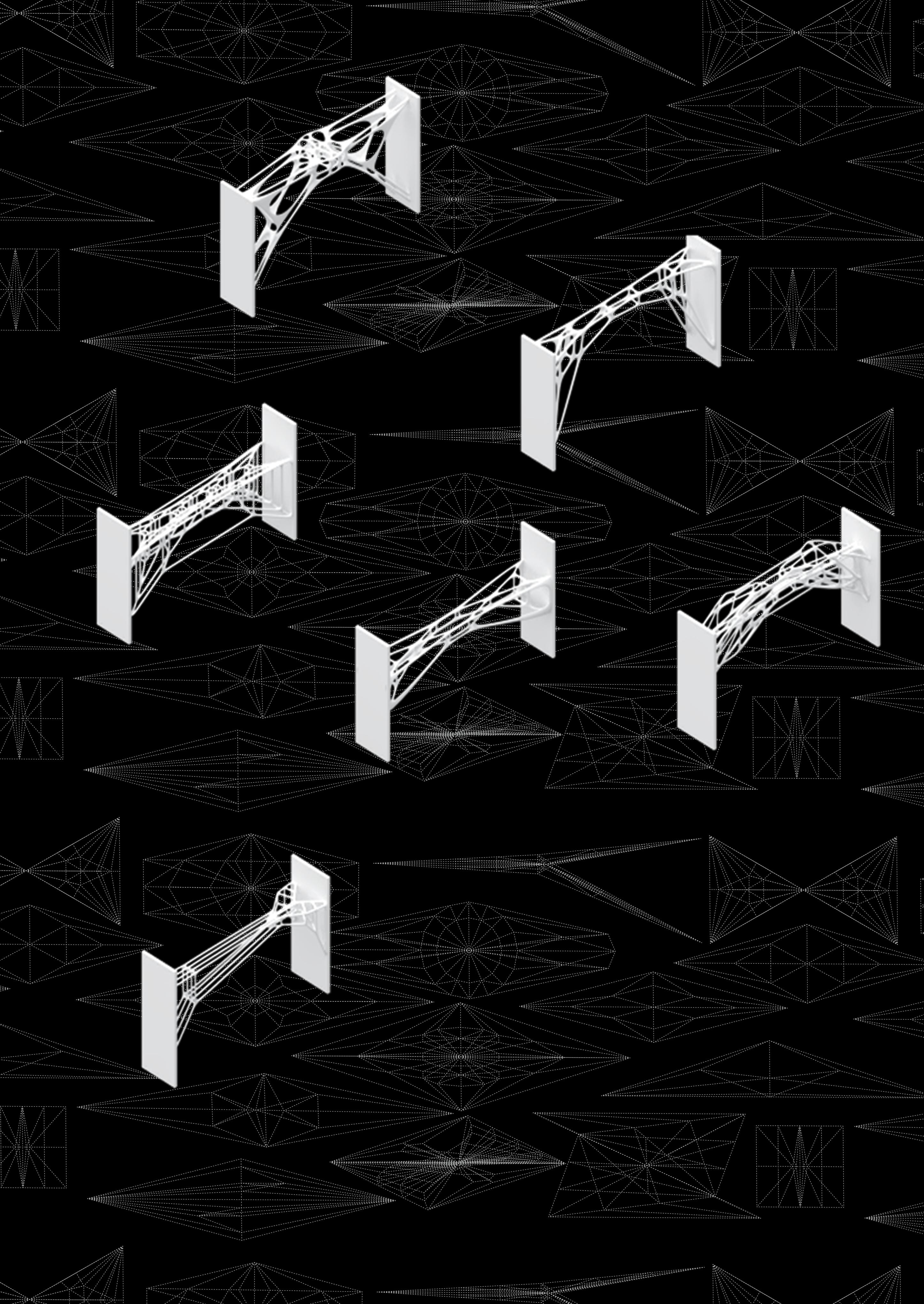
INTELLIGENT FORCE PRINTING
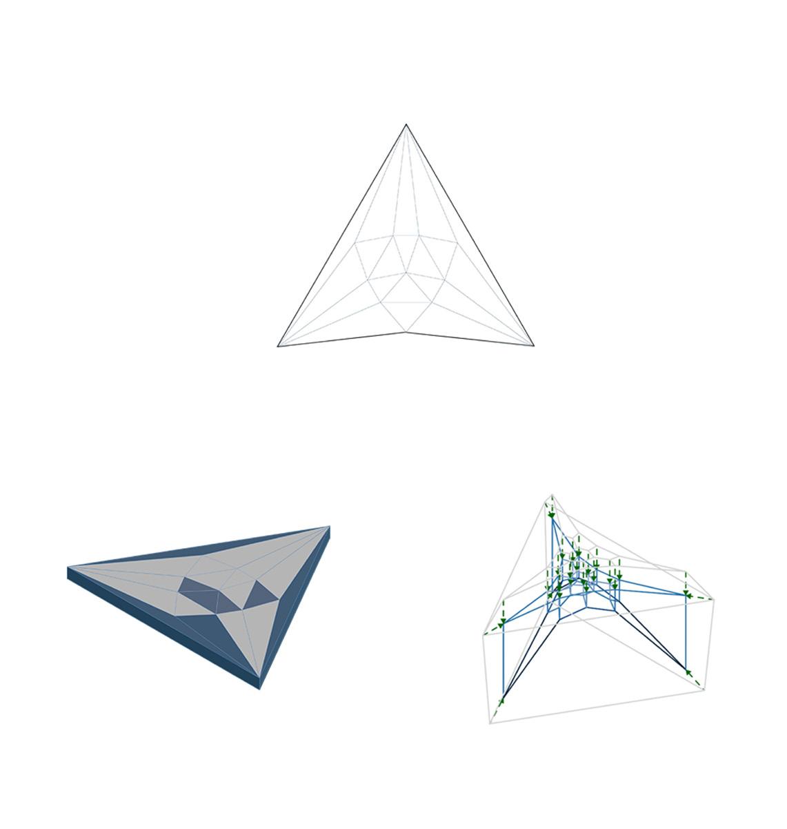
Form Diagram Form Diagram Force Diagram Force Diagram
Form Diagram
Force Diagram
Form Diagram
Force Diagram
ORO Editions
ORO Editions
ORO Editions
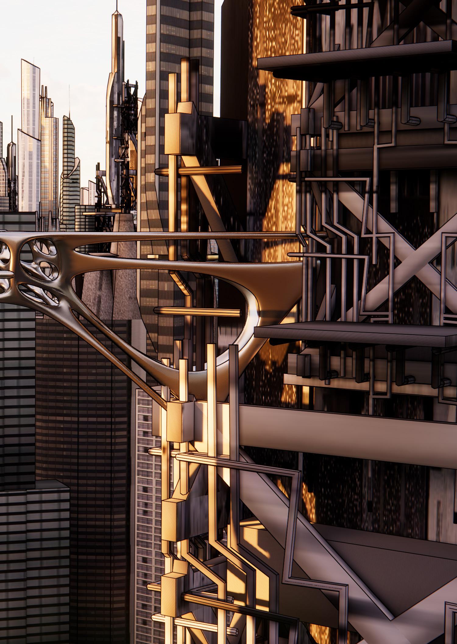
ORO Editions
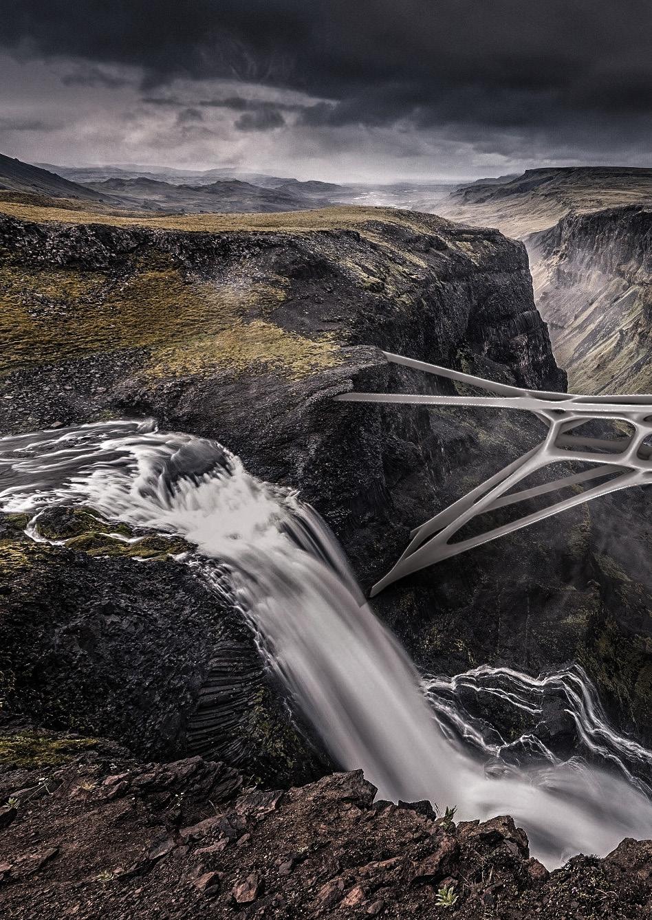
ORO Editions
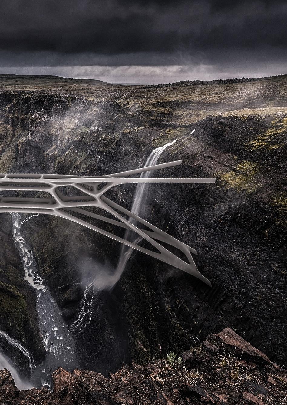
ORO Editions
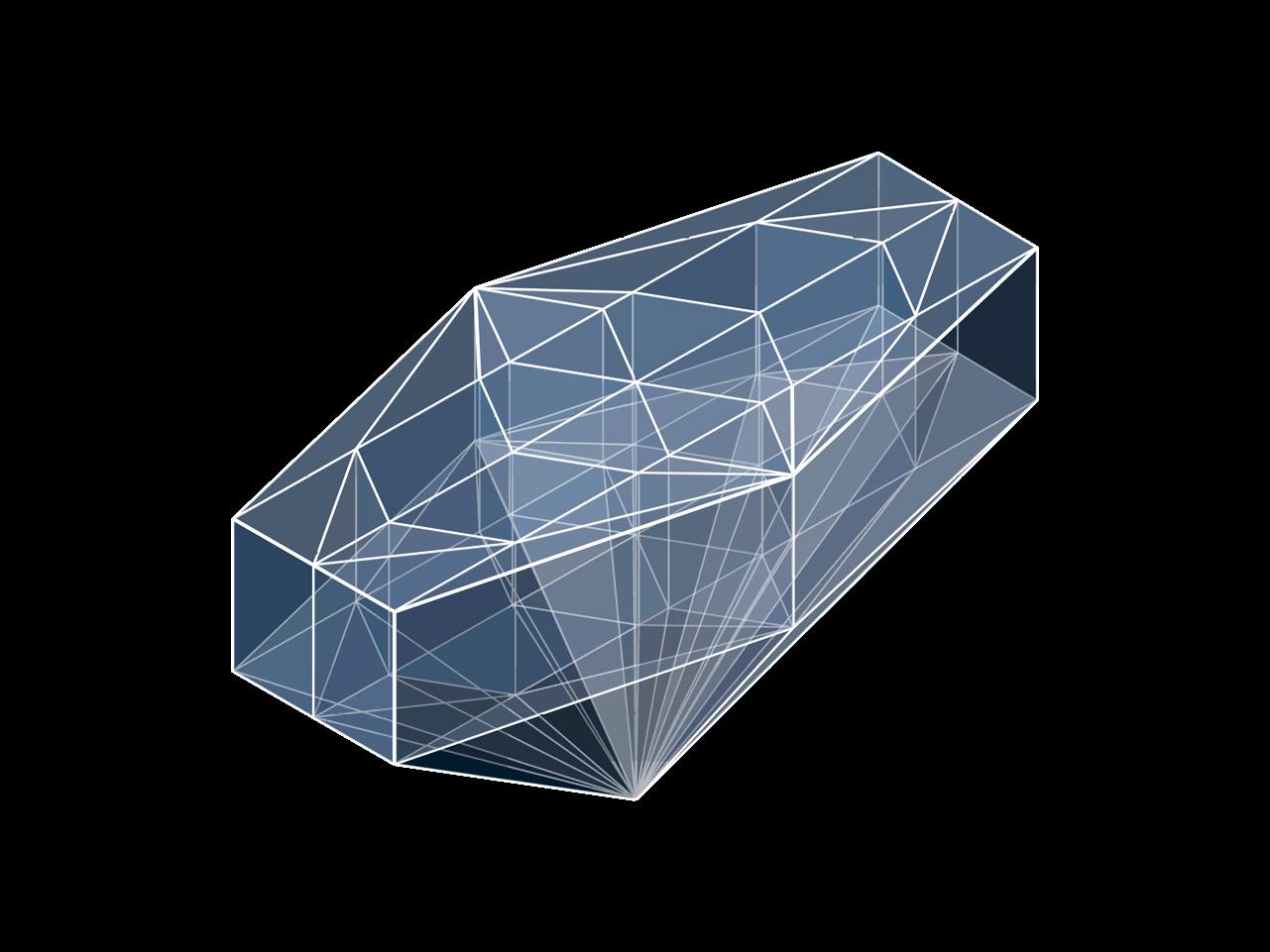
Perspective Diagram - Zhengqian Peng
Form Diagram
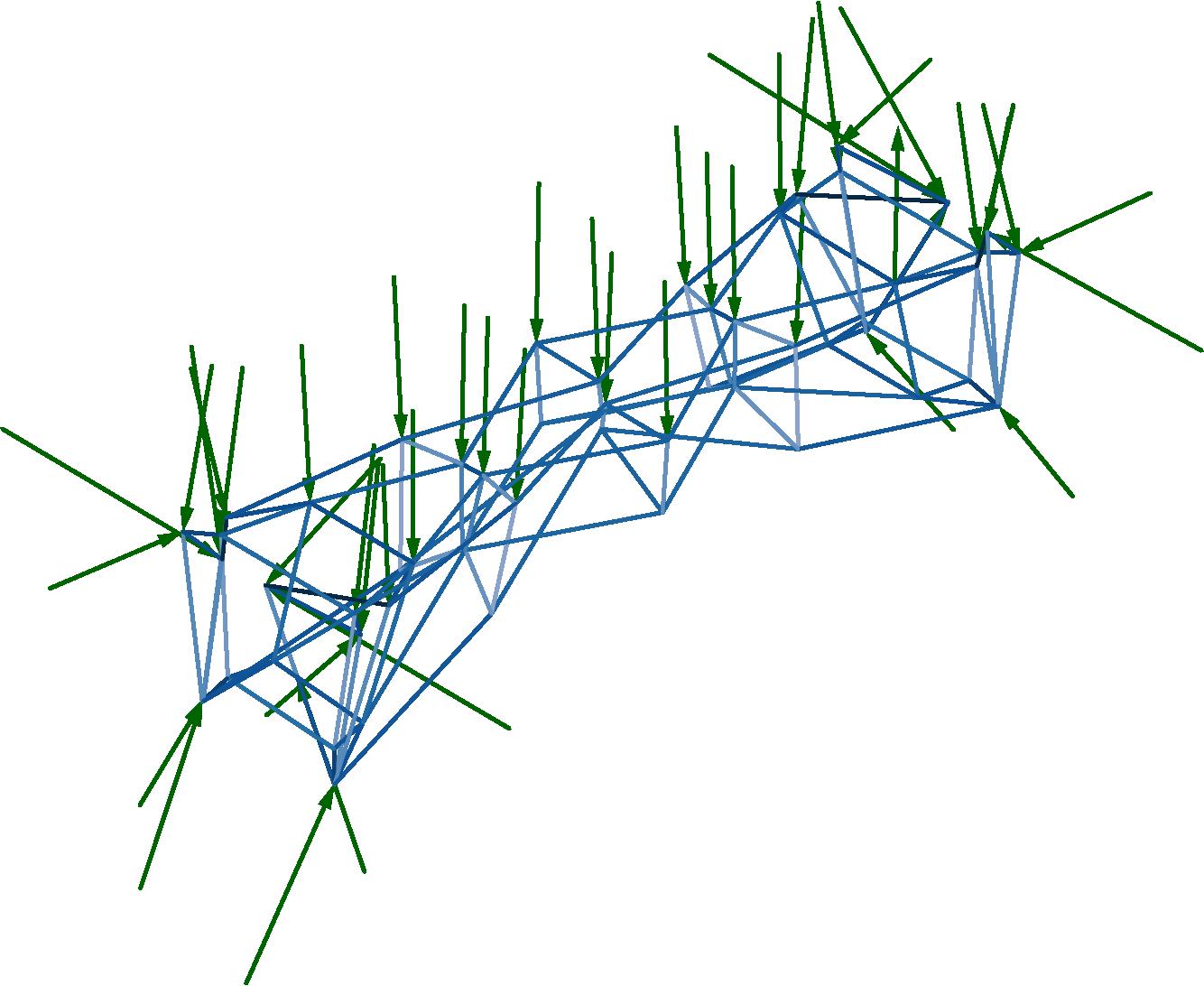
Force Diagram
Feedback
It is not compress-only, you have convex cells. For some reason, you have complex cells when you should have self-intersecting cells, that means that your system is not compression-only. Also when you combine compress and tension, it does not work well. Pull to the point.
BRIDGE DESIGN
Plan the view in your bridge; self-interesting cell mixed forces (compress & tension).
Design Process
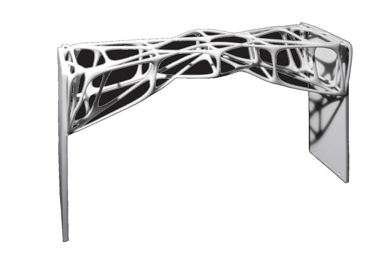
UNACCOMPANY
Bowen Li
Zhangxizhi Wang
Zhengqian
Peng
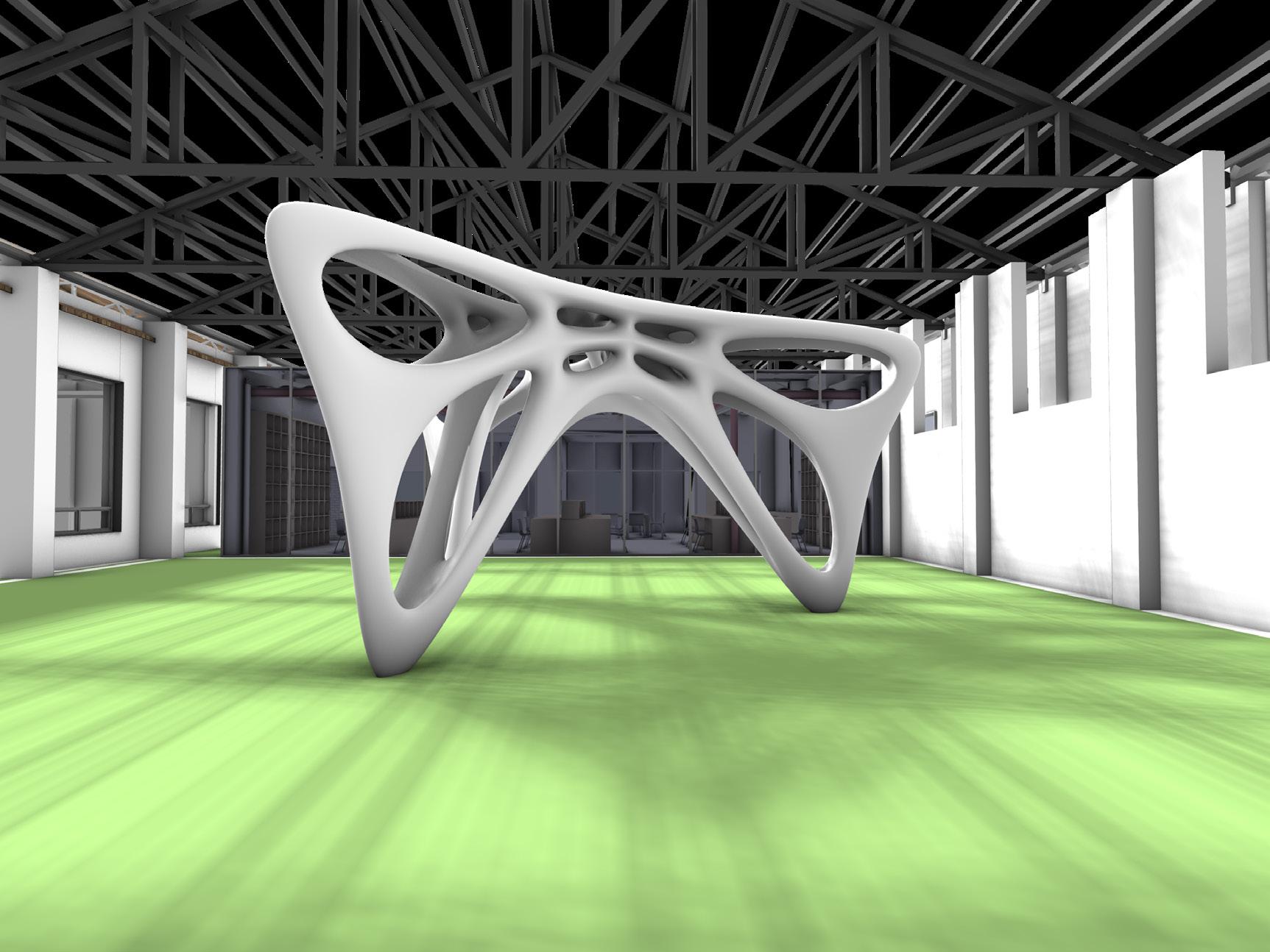
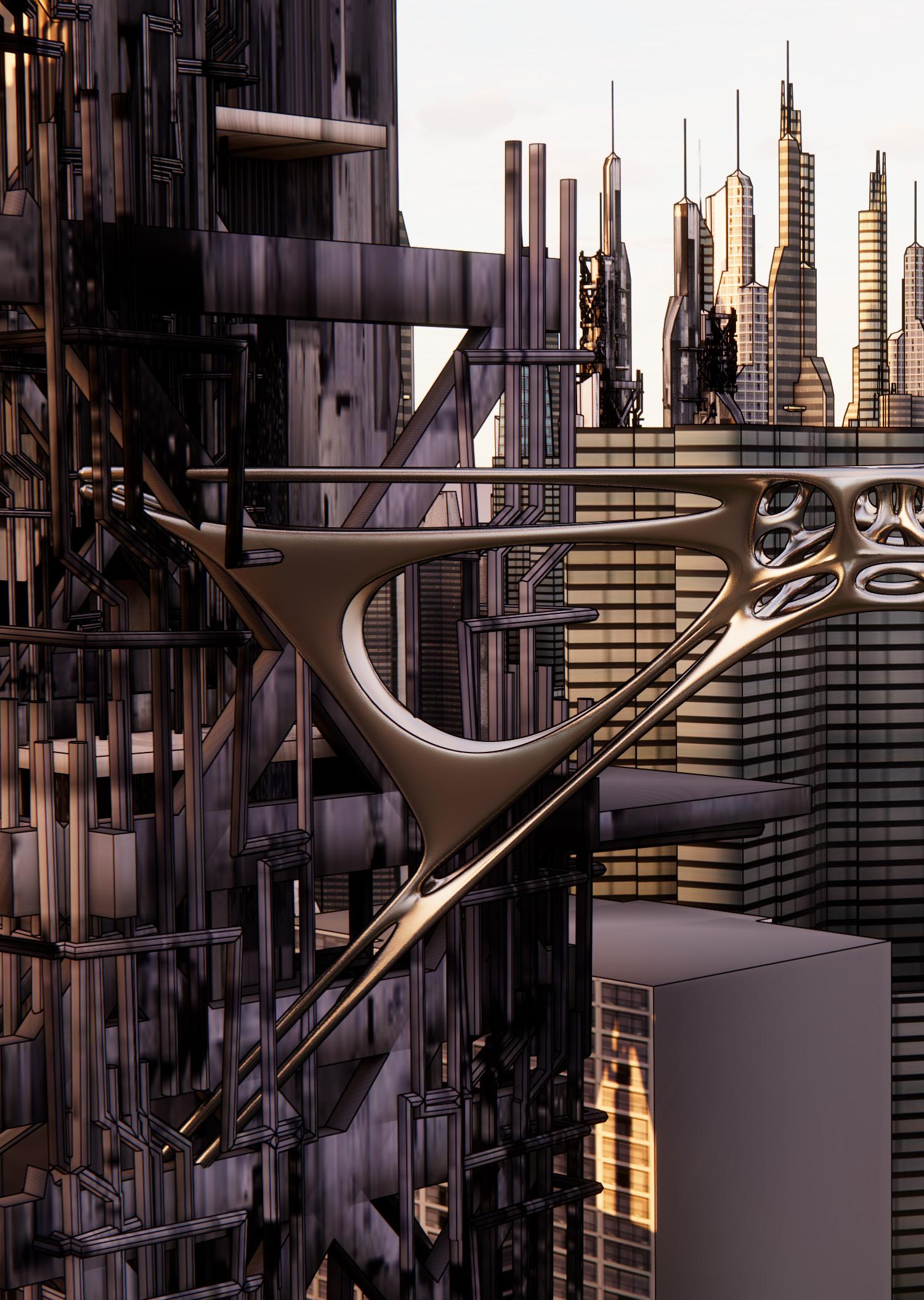
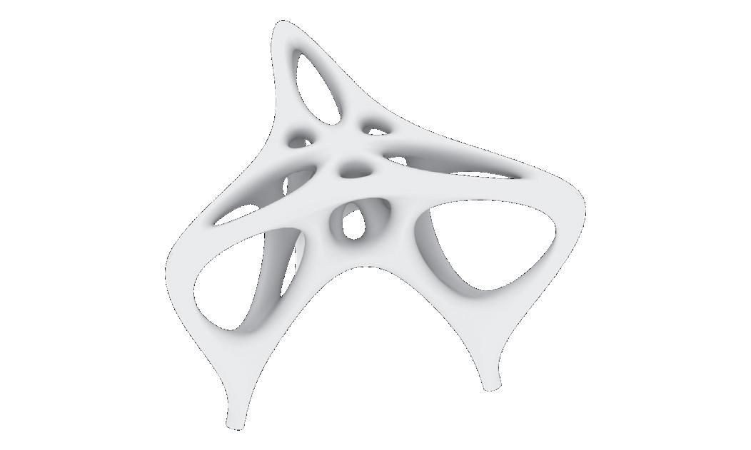
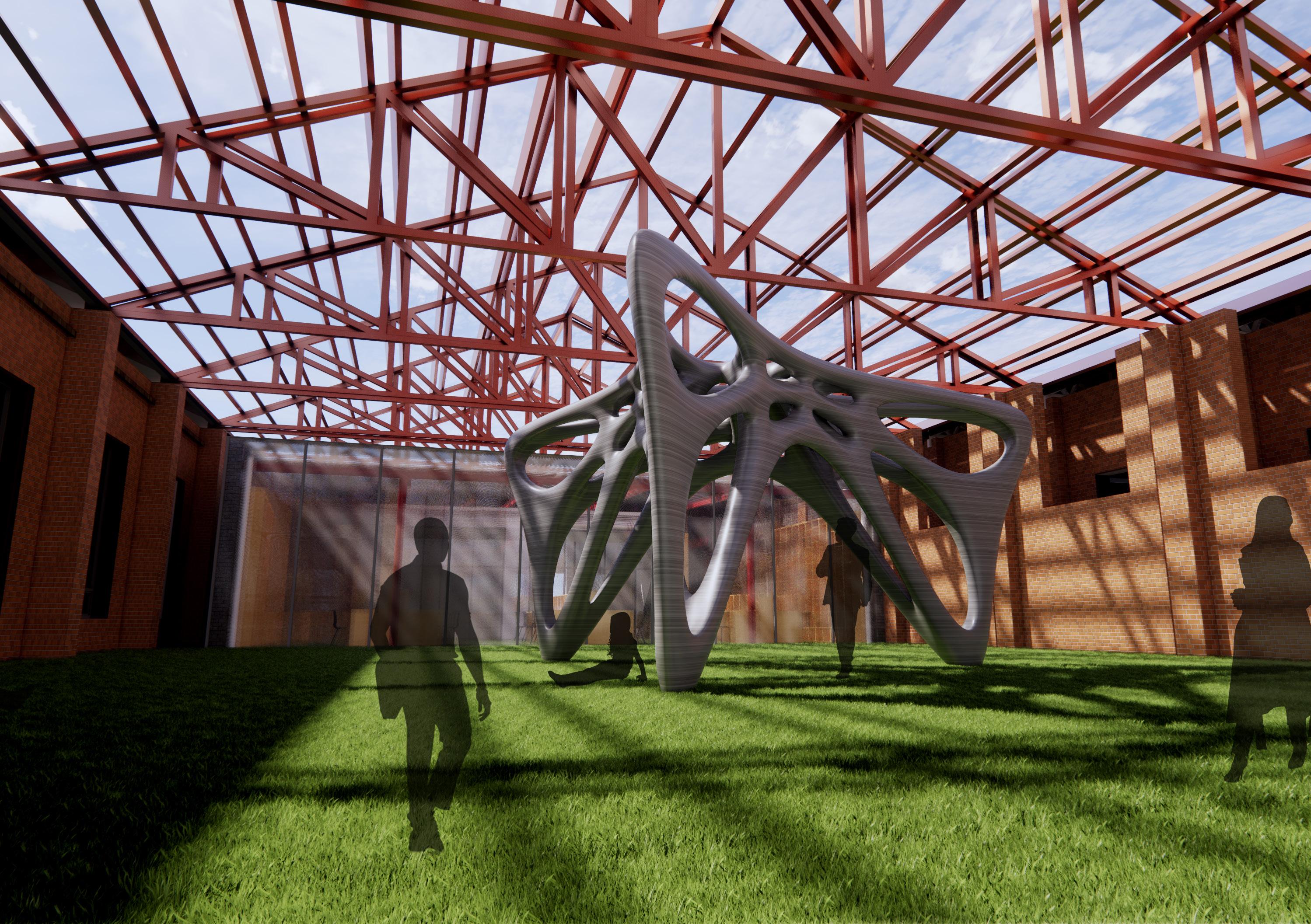
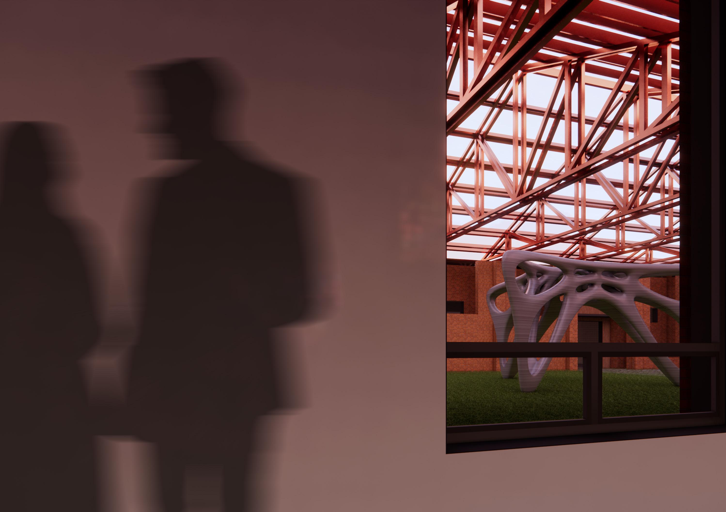
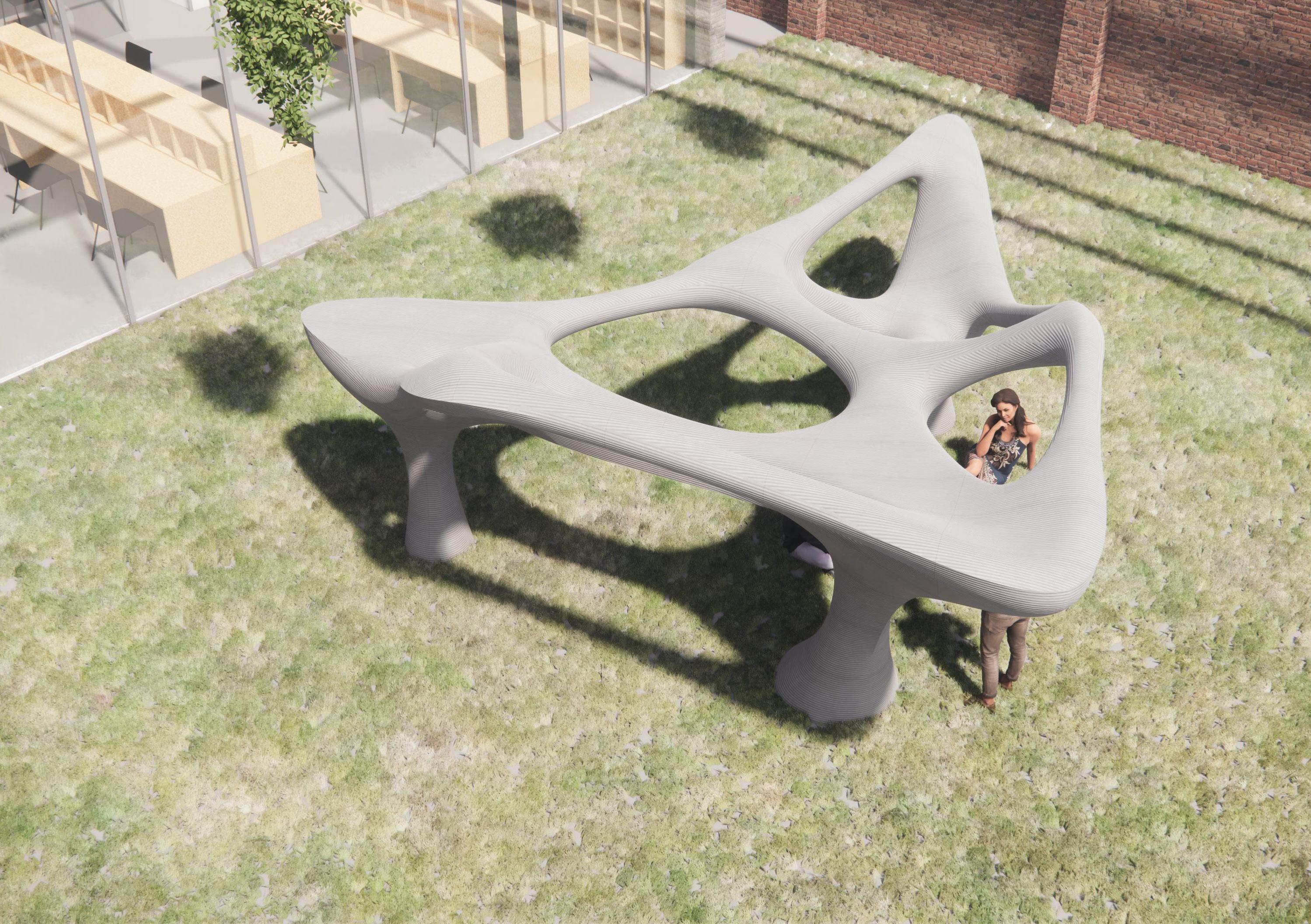
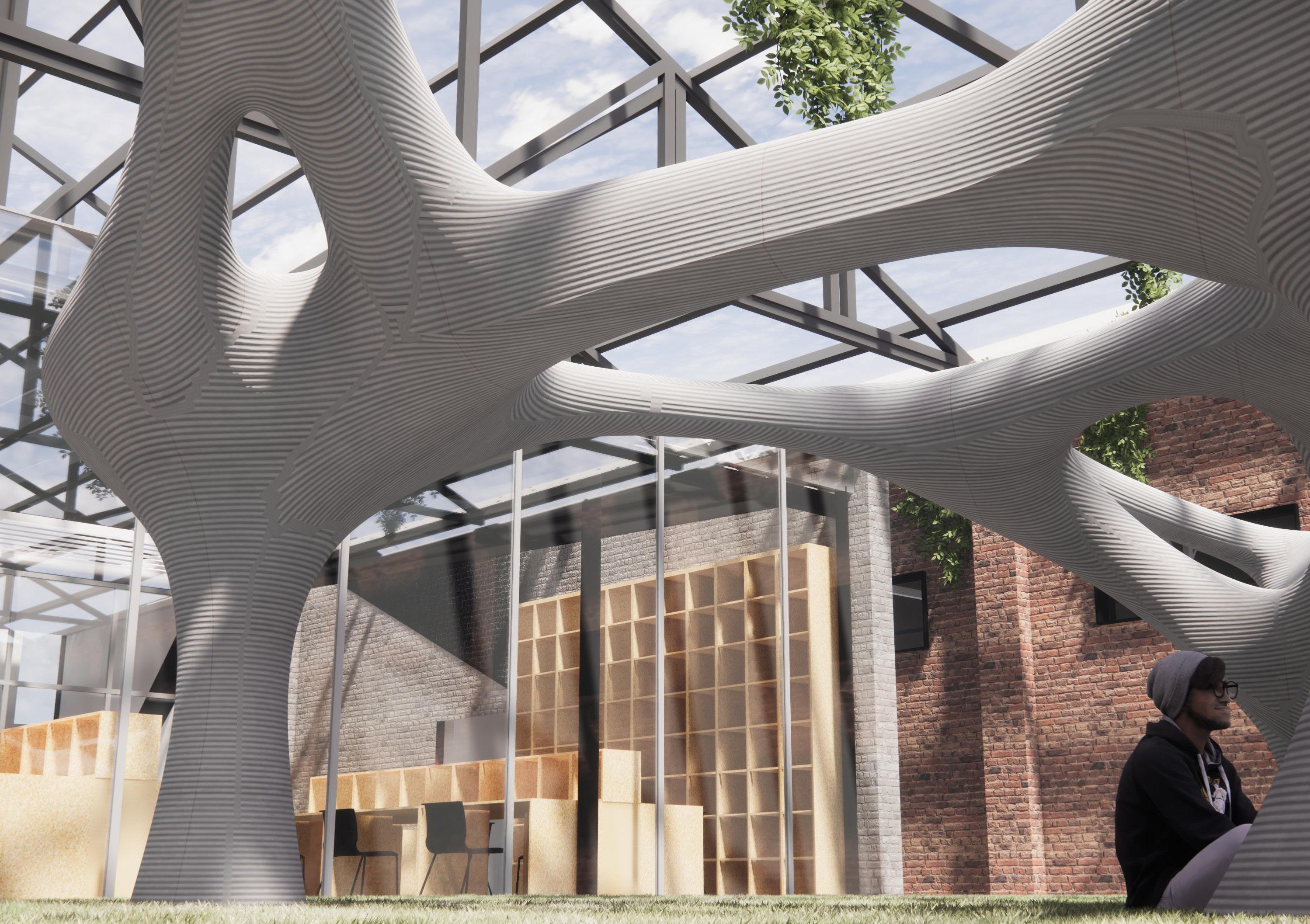
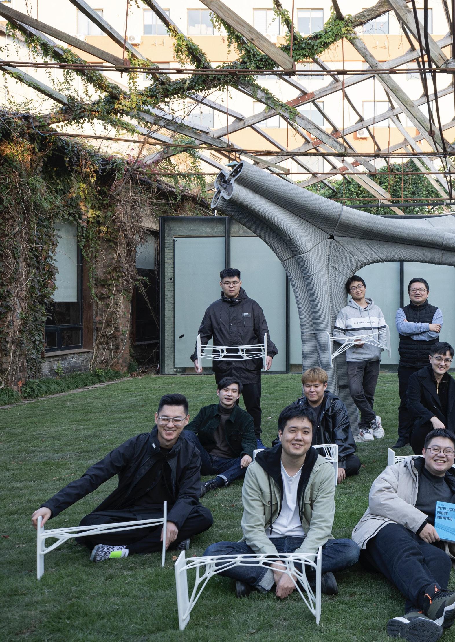
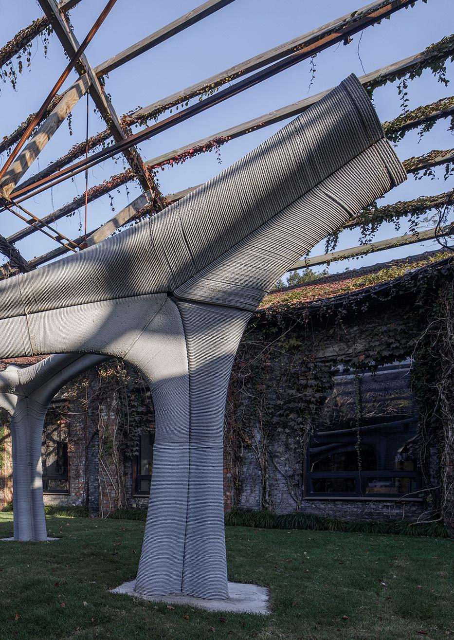
Crafted with precision, UNACCOMPANY stands as a centerpiece within a space of industrial symmetry, its sweeping curves and bold apertures a stark contrast to the orthogonal lines of its surroundings. This piece is not merely a static installation but a dynamic entity that reshapes the essence of the space it inhabits.
ORO Editions
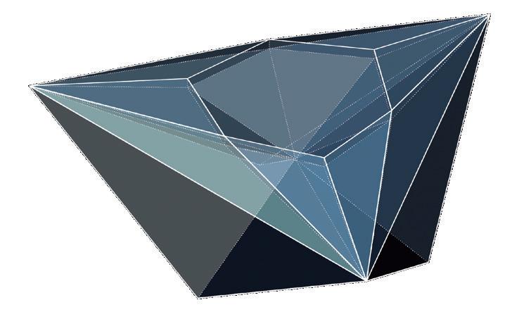
Force Diagram
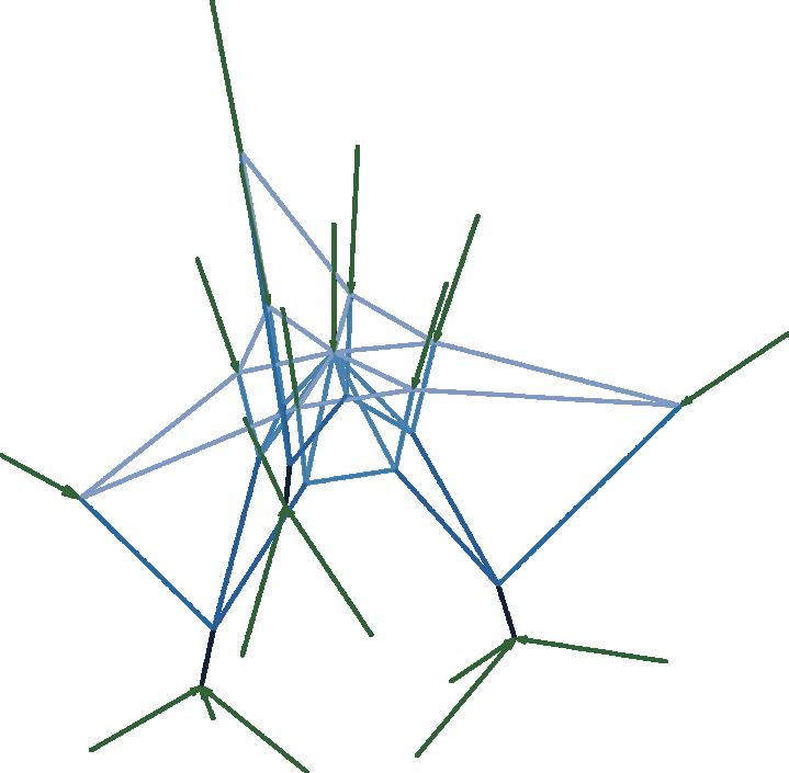
Form Diagram

ORO Editions
Reinforcement
Stage 3
Stage 4
Ring Beam
ORO Editions
ORO Editions


ORO Editions
ORO Editions
