
Determination of Tension Strength of Equipment Pressure Spring Measuring Developing Depth
Abduvahobov D.A., Khaydarov K. S., Gofurjanov I. I NamMQIANNOTATION
The article notes the development of a device for measuring the working depth of tillage machines and the results of research to determine the tensile strength of the pressure spring. According to the results of the study, the required tension force of its pressure spring should be 270 N in order to ensure that the support wheel of the device for measuring the working depth of tillage machines is constantly pressed on the field surface and copies the irregularities in it.
KEYWORDS: tillage depth, tillage depth determining device, parallelogram mechanism, base wheel, electronic block, data transmission and reception devices.
At present, the working depth of tillage machines is determined using labor intensive and low precision methods (obtaining cross-sectional and longitudinal profiles with the participation of at least 2 3 people, dipping a ruler into the treated layer, measuring the height of the furrow wall with a rake, etc.) [1 , 2] .Then the data are first obtained, then their statistical characteristics are determined. This takes a lot of time and does not allow you to get feedback and constantly monitor the operation of the unit.
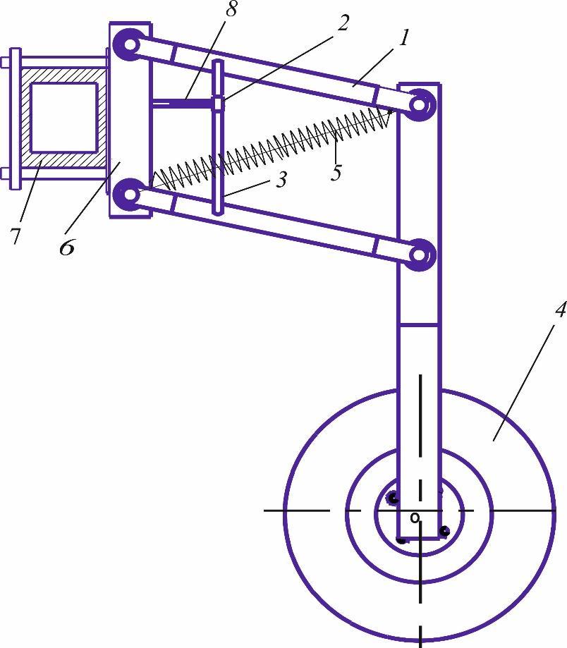
Based on the above, on the basis of the analysis of the devices for determining the depth of tillage [3 5], a device for measuring the working depth of tillage machines in a mechanized way was developed. It consists of an electronic module consisting of a parallelogram mechanism 1 (Fig. 1), an electronic block 2 and a rod 3, which is fastened to the machine frame 7 by means of a lock 6. The rod of the electronic module is hinged to the pulls of the parallelogram mechanism, while the electronic block 2 is fixed to the lock 6 by means of a handle 8 which can change its length. The device is based on measuring the depth of immersion of the working bodies and works in the following order: when the working bodies of the machine sink to a certain depth, the base wheel 4 of the device rises to a height equal to the initial position, ie the depth of immersion of the working bodies. and transmits it to the data transmission device (this device is not shown in Figure 1). The transmitted data is received by the data receiver, displayed on a laptop screen in the form of a graph or number, and their statistical characteristics are determined.
For the device to work reliably, its support wheel must work without interruption from the field surface and copy the irregularities in it. To do this, the base wheel of the device must be constantly immersed in the field surface with a certain force. This is achieved when the following condition is met [6]
There ZQ is the vertical pressure on the field surface of the device support wheel power, N; m ZQ ZQ the optimal value of the force that ensures uninterrupted operation of the base wheel on the field surface and the copying of irregularities in it, N. (1)
Middle European Scientific
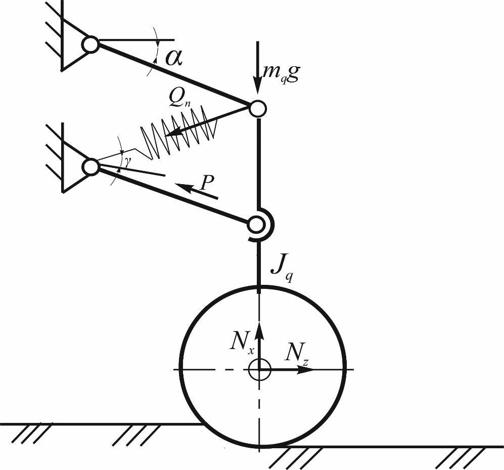
2 shows the forces acting on the device during operation. Using it, we determine the pressure force on the field surface of the base wheel of the device:
and
given that
In this , ZXNN the vertical and horizontal components of the reaction force acting on the base wheel of the device by the ground, respectively, N; device rolling resistance of the base wheel coefficients; from the horizon of the parallelogram mechanism traction deflection angle, °; q m the mass of the device, kg; g free fall acceleration, m/s2 ; nQ the tensile strength of the device pressure spring, N; the tensile strength of the device pressure spring angle of inclination relative to the horizon, °; q J the force of inertia generated by the support wheel of the device copying the irregularities on the field surface, N.
Figure 1. Schematic of the device Figure 2. Schematic of the forces acting on the device during operation
Middle European Scientific Bulletin,
(3) Analysis of the expression shows that the condition (1) for a given operating condition and therefore the reliable operation of the device is mainly ensured by the correct adjustment of the tension force of the spring.
(3) From expression (1) we obtain the following expression to determine the tensile force required for a given operating condition of the device pressure spring
In this
the required tension of the device pressure spring power, n.
on the field surface in the direction of movement
is the ordinate of the irregularities, m; Z0 is half the height of the roughness, m; V speed of movement, m / s; t time, s;
assuming that the length of the irregularity, m) varies according to the harmonic law, the force of inertia resulting from the copying of these irregularities by the support wheel of the device is determined by the following expression
this Z the acceleration of the base wheel of the device along the ordinate axis, m/s2 Given the maximum value of the inertial force, expression (4) has the following form
The analysis of this expression shows the value of the tensile force required for a given operating condition of the device pressure spring, the value of the vertical pressure force of the base wheel on the ground to ensure its continuous operation on the field surface and the copying of irregularities, the coefficient of rolling resistance, parallelogram mechanism tensioners mass, depending on the size (height and length) of the unevenness of the field surface and the speed of movement of the aggregate.
ZQ = 500 N, = 0,2, = 10°, q m = 50 kg, 0Z = 0,1 m, l = 10 m, V = 3,0 m/s, = 45° = 500 N, = 0.2, = 10 °, = 50 kg, = 0.1 m, = 10 m, = 3.0 m / s, = 45 ° the required tension force of its pressure spring must be 270 N in order for the wheel to be constantly pressed against the field surface and to copy the irregularities in it and therefore to ensure reliable operation of the device.
EUROPEAN SCIENTIFIC BULLETIN
Conclusion: Our research shows that the required tension force of its pressure spring must be 270 N in order for the support wheel of the device for measuring the working depth of tillage machines to be constantly pressed on the field surface and copy the irregularities in it and therefore ensure reliable operation of the device.
REFERENCES
1. Abduvahidovich A. D., Jobirhon M., Hakimovich U. A. Layout diagram of the hinged oscillatory spike tooth harrow and determination of its row spacing width // European science review. 2016. №. 5 6.
2. Abduvaxobov D. A., Madraximova M. B., Krygin S. E.. Ravnomernost xoda pochvoobrabatыvayushix mashin po glubine obrabotki i ix ustoychivost // Vklad universitetskoy agrarnoy nauki v innovatsionnoe razvitie agropromyshlennogo kompleksa. 2019. С. 8 11.
3. Abduvakhobov D.A., Xaydarov K.S., Imomov M.X., Mamadaliyev I. Justification of parameters tooth harrow copying field relief // International Journal of Advanced Research in Science, Engineering and Technology. - India, 2020.-№7, Issue 12 pp. 14049-14053.
4. D.A. Abduvahobov, K.S.Khaydarov, & M.B.Madraximova. (2021). Method Of Determining The Sustainability Of Working Depth Of Earthquaking Machines With Digital Device. The American Journal of Engineering and Technology, 3 (05), 156 159.
5. Abduvahobov D., Khaydarov K., Madraximova M. Device for measuring the depth of cultivation and its stability in an automated way // International scientific conference "The role of international farmers in the introduction of innovative technologies in the integration of production, science and education in agriculture. " Namangan, 2020. P. 287 291.
6. Burchenko P.N. Mechanical technological bases pochvoobrabatыvayushchix mashin novogo pokoleniya. Moscow, VIM, 2002. 212 p.
7. Tuxtakuziyev A., Abduvahobov D.A., Komilov N.M., Khaydarov K.S. Development of software for automatic control of tillage depth of tillage machines // UzR. IMA Certificate for Exposure Program. № BGU 00564 17.03.2022