
ARC382_ArchitecturalDetailing_FinalBinder

Page 1

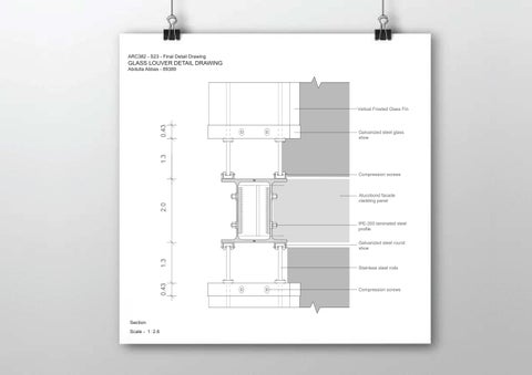
ARC382 - S23 - Final Detail Drawing

GLASS LOUVER DETAIL DRAWING

Abdulla Abbas - 89389

Vetical Frosted Glass Fin

Galvanized steel glass shoe

Compression screws

Alucobond facade cladding panel

IPE-200 laminated steel profile

Galvanized steel round shoe

Stainless steel rods

Compression screws

Section Scale - 1: 2.6

2.0
1.3 0.43 1.3 0.43
MURABA LOUVER RESEARCH -------------------------- 01 INTRODUCTION MATERIAL LIBRARY SKETCHES MURABA LOUVER DESIGN PROPOSAL -------------- 01 TECHNICAL DRAWINGS RENDERS JAPANESE JOINT DETAILS -------------------------------- 01 TECHNICAL DRAWINGS RENDERS TABLE
CONTENTS S--------------------------------------------- 01 S----------------------------------------- 01 S--------------------------------------------------- 01 S------------------------------------ 01 S--------------------------------------------------- 01 S------------------------------------ 01 S--------------------------------------------------- 01
OF

Research

RCR Architects

About

The trio consisting of Rafael, Carme, and Ramon, are architects who graduated from the Escuela Técnica Superior de Arquitectura del Vallès (ETSAV-UPC) in 1987. They have been working together under the name RCR Arquitectes with their team and were established in 1988. Additionally, they each earned a Master’s Degree in Landscape Architecture. They have taught Architectural Projects in Vallès and Barcelona, as well as Urban Planning and Landscape Architecture in the Vallès. h

Ideology

RCR Architects has long been recognized for its design approach that emphasizes the use of unique materials, their consideration of the site and surroundings, and creation experiences that engage the senses. The firm values the relationship between architecture and nature and frequently incorporates natural elements and materials into their designs. The aim of their work is to evoke emotions and foster a connection between people and their surroundings. The projects they create are distinguished by their sophistication, elegance, and incorporation of traditional building methods and materials in a creative, contemporary manner. j

Achievements

The firm throughout the years has won several awards, competitions and other accomplishments. These achievements act as a symbol of their influence and contribution on the world of archietcture; some of them are the following: g

The Pritzker Prize (2017), RIBA European Award (2010), Venice Biennale Golden Lion for Lifetime Achievement (2016), UIA Gold Medal (2015), National Architecture Prize of Spain (2005), FAD Architecture Prize (1999) n

Past Projects

De Krook City Library, Ghent, Belgium Theatre La Lira, Ripoll, Spain Sant Antoni - Joan Oliver Library, Barcelona, Spain

What are the Muraba Apartments? h

Muraba Residences is the first large-scale residential development completed by RCR Arquitectes, it is architectural magnificence set on the eastern crescent of the Palm Jumeirah, Dubai. “Muraba Residences Palm Jumeirah is set to be exactly as per the design promise; an exceptional living space on the East crescent of Palm Jumeirah with a focus on style and design,” said Ibrahim Al Ghurair, the founder of pioneering real estate developer Muraba. j

The term ‘muraba’ is derived from the Arabic word for watchtower, which is what heavily inspired the building’s form starting from the balconies and floor-to-ceiling glazing frame the sea, the sky and trajectory of the sun. Like its name suggests, Muraba is a secure and intimate living space that embodies an ideal of essential beauty infused with serene elegance. k

The Muraba Residences seek to optimise the changing effects of daylight throughout the day, all while providing the privacy required by the occupants and those who call the apartments home. Muraba Residences have been dessigned ‘from the inside out’, with the resident in mind. j

Designing the Muraba Apartments

Adhearing to RCR’s designing ideologies, the building’s design responds directly to its context, with its orientation determined by the trajectory of the sun and the windows and balconies pointed towards the views. The building facades are oriented in a manner to make the most of the uninterrupted views accross the water alongside the skyline of the whole of Dubai. The building is aligned not only in its physical location, with the rising and the setting of the sun, but also with a specific sort of mindset that it applies to the spaces; a mindset that would be appreciative of more sophisticated architecture, as well as keen attention to detail. Creating spaces that are private, minimal and peaceful. h

The Muraba Residences consisted of over three thousand cast, tempered and laminated glass fins, mounted infront of the windows. The vertical fins over 3 metres long, and 27 mm thick. provide privacy from adjacent buildings, while affording a view over the sea in the other direction. Being located on the palm islands by the water, the wrinkled glass effect mimics the serenity of the surrounding waves in the site. j

Materials Library

1. Precast GRC Panels - Variable LengthDepth 9cm 6. Bottom Galvanized Steel Bracket for vertical panel with tridimensional adjustment -High Resistance (screws, nuts, bolts) 11.Steel Reinforced Concrete Slab 12.Galvanized Steel Plate embedded in concrete slab for IPE200 - steel profile fixing 13. HALFEEN built-in galvanized steel channel for panel fixing adjustment - Length 20cm 14.High Resistance Steel Fixing Screw 15.20mm Insulation Block-Work at Site 7. Top Galvanized Steel Bracket for horizontal stabilization and fixing with tridimensional adjustment -High Resistance hardware (screws, nuts, bolts) 8. Clay Hollow Block Wall (width 10 cm) for facade envelope enclosure, with access points for adjustment of panel fixing 9. Thermal Insulation Embedded within GRC Panels ribs 10. Gpysum Board False Ceiling 2. Joint Sealing between GRC panels and profiles (Silicon Cornering 813C - same color as panel) 3. IPE200 - Laminated Steel Profile (2 layers of antioxidant primer coating, highly resitant to marine enviroment - same color as natural aluminium in window frames) 4. Interior dry wall (composed of 45mm galvanized steel profile, inner thermal insulation (rockwool), 2 gypsum boards of 13mm) 5. Travertine Stone Paving - Variable width 22/14/10 cm - Variable Length 70/60/50/40/30/20 cm - Depth 2cm - Laid on 6cm leveling cement mortar screed 16. Panel preinstalled screw for bracket fixing 21. ALUCOBOND facade cladding panel - Side enclosure panel (same color as natural aluminum in window frames) 26. Profile steel “U” to support the glass balustrade, mechanically attached to the structural slab 27. Galvanized steel plate fixed to the slab with high-strength bolts 28. Frame steel plates to support main glass railing. Finished with two coats of primer and two coats of finish paint 29. Auxilary structure of tubular galvanized steel to hold the plates, anchored to the structural slab 30. Vertical wrinkled glass - 2 layers of laminated glass - Variable depth - Horizontal wrinkled glass transition 22. Facade thermal insulation 23. Fixed window hidden profiles with insulating glass 24. Painted steel facade cladding panel (same color as natural aluminum in window frames) 25. Laminated glass railing recessed bottom steel profile 17. Vertical wrinkled glass fin, 3 layers of laminated glass 18. Galvanized steel element for support fixing of glass fins, fixed to steel plate with compression screws 19. Structural steel plate factory pre-welded to IPE-200 profile - 2 layers of antioxidant primer coating - 2 layers of paint coating. Highly resistant to marine enviroment (same color as natural aluminum in window frames) 20. ALUCOBOND facade cladding panel (same color as natural aluminum in window frames) Detail sketch of GRC panels
01 15 03 09 12 07 16
Zoomed in section
Section 09 03 16 01 05 11 12 07
Detail sketch of GRC panels
Detail sketch of glass louver Section 17 03 18 20
Detail sketch of glass louvers Axonometric 03 18 17 20 11
Plan 22 17 18 21 15
Detail sketch of glass louvers
Zoomed in plan 20 21 17 18 03
Detail sketch of glass louvers Detail sketch of glass shoe Axonometric

Detail sketches of glass fins

Perspective + Axonometric

MURABA LOUVER DESIGN PROPOSAL
Vertical frosted glass fin- 2 layers of translucent glass Transparent film between layers of glass Galvanized steel glass shoe Galvanized steel round shoe holding steel rods Stainless steel rods Compression screws 16 15 15 09 10 16 04 08 11 02 2.8 2.06 25.7 27.6 4.4 4.8 13 07 03 14 06 11 17 06 06 06 18 18 2.8 2.8 2.8 2.8 2.8 2.8 2.8 2.8 2.8 2.8 2.8 2.8 2.8 Facade details Plan, Section, Elevation
Vertical frosted glass fin- 2 layers of translucent glass Transparent film between layers of glass Galvanized steel glass shoe Galvanized steel round shoe holding steel rods Stainless steel rods Compression screws Zoomed in section detail drawing Detail A2 2.0 16 02 18 18 15 17 06 08 09 1.3 0.43 1.3 0.43
Vertical frosted glass fin- 2 layers of translucent glass Transparent film between layers of glass Galvanized steel glass shoe Galvanized steel round shoe holding steel rods Stainless steel rods Compression screws Zoomed in plan detail drawing 2.8 4.8 06 17 14 15 1.0 0.27 2.8 2.8 Detail A1 2.8 2.8 2.8
Vertical frosted glass fin- 2 layers of translucent glass Transparent film between layers of glass Galvanized steel glass shoe Galvanized steel round shoe holding steel rods Stainless steel rods Compression screws Zoomed in individual louver detail drawing 2.8 1.0 0.27 15 14 16 17 06 0.27
Vertical frosted glass fin- 2 layers of translucent glass Transparent film between layers of glass Galvanized steel glass shoe Galvanized steel round shoe holding steel rods Stainless steel rods Compression screws
Axonometric A Drawing of steel rod shoe
Zoomed in axonometric detail drawings
Axonometric B Drawing of glass shoe
Vertical frosted glass fin- 2 layers of translucent glass Transparent film between layers of glass Galvanized steel glass shoe Galvanized steel round shoe holding steel rods Stainless steel rods Compression screws Exploded axonometric louvers detail
C
Axonometric
Drawing of glass louver
Exterior Building Render Exterior Building Render- Zoomed in
Closeup Exterior Render
Closeup Interior Render
Interior Perspective Render Exterior Facade Render
JAPANESE JOINT DETAILS

Chidori Joint History

The Chidori Joint was developed by Kengo Kuma in the 1990s, as part of his exploration of traditional Japanese architecture and techniques. Kuma was particularly interested in the joinery systems used in traditional Japanese timber construction, which he saw as a way of creating strong, resilient structures that were also aesthetically pleasing

Kuma’s goal was to create a joint system that was both strong and flexible, allowing for natural movements in the building while also maintaining its structural integrity. The Chidori Joint is designed to accomplish this by using a series of angled cuts and overlapping pieces that interlock to create a secure connection

Chidori is a Japanese word that refers to a type of bird called a plover. In traditional Japanese culture, the plover is associated with various meanings, such as the arrival of spring or good luck. In the context of the Chidori Joint, the name was chosen because the shape of the joint resembles the beak of a plover

The joint was also initially inspired buy a popular japanese kids toy that also was called Chidori

Contemporary Design

In modern times, Kengo Kuma has continued to use the Chidori Joint in many of his architectural designs, both in Japan and around the world. One notable example is the Asakusa Culture and Tourism Center in Tokyo, which features a striking façade made up of interlocking wooden slats held together by Chidori Joints. The joint’s unique design allowed Kuma to create a building that appears to be a natural extension of its surroundings, with a visually striking façade that references traditional Japanese architecture

Kuma has also used the Chidori Joint in other projects, such as the SunnyHills at Minami-Aoyama in Tokyo, which is a flagship store for a Japanese confectionery company. The building’s façade is made up of wooden slats held together with Chidori Joints, creating a lattice-like effect that allows natural light to filter into the interior

Kengo Kuma’s incorporation of the Chidori Joint even in his modern designs highlights its continued relevance as a construction technique that blends traditional Japanese craftsmanship with contemporary design principles

Axonometric + Elevations Module A
Igor Peraza Japanese Joints Chidori Joint Igor Peraza
Module B Module C Module A Module A Module B Module C
Axonometric + Elevations Module A 50 150 150 50 50 50 50 50 150 150 50 50 50 50 50 50 50 50 150 150 50 350 50 50 50 350 50 50 350 50 150 150 350 Igor Peraza Japanese Joints Chidori Joint Igor Peraza Module A Axo Front Elevation Right Elevation Left Elevation Back Elevation Bottom Elevation Top Elevation
Axonometric + Elevations Module C 50 150 150 50 50 50 50 50 150 150 50 50 50 50 50 50 150 150 50 50 50 50 50 25 350 50 50 50 150 150 350 25 150 150 25 150 175 25 Igor Peraza Japanese Joints Chidori Joint Igor Peraza
A
Front Elevation Right Elevation Left Elevation Back Elevation Bottom Elevation Top Elevation
Module
Axo
Axonometric + Elevations Module B Igor Peraza Japanese Joints Chidori Joint Igor Peraza 350 350 50 50 50 50 50 50 50 50 50 50 50 50 25 25 150 175 150 150 25 20 25 20 150 150 25 5 20 5 5 50 50 50 50 150 150 50 350 Module A Axo Front Elevation Right Elevation Left Elevation Back Elevation Bottom Elevation Top Elevation
Axonometrics + Sections 25 25 25 25 25 50 50 Igor Peraza Japanese Joints Chidori Joint Igor Peraza Sections AA,BB
Section AA Axonometric Section BB Axonometric Section AA Section BB
50 50 50 50 50 50 50 50 25 25 25 50 Igor Peraza Japanese Joints Chidori Joint Igor Peraza Axonometrics + Sections Sections CC,DD
Section CC Axonometric Section DD Axonometric Section CC Section DD Exterior

Art Exhibition Pavillion

The design of the pavillion is in the form of an art gallery exhibition. The Chidori Joint’s unique characteristics make it an excellent choice for timber construction in general, and specifically for creating an art gallery pavilion. The joint’s strength and flexibility are crucial in a pavilion’s construction, as it needs to withstand external forces while also accommodating natural movements caused by wind, earthquakes, and other factors. Additionally, the joint’s aesthetic appeal adds a unique and recognizable character to the pavilion, enhancing its overall design. Art is highly regarded in Japan and plays an essential role in the country’s cultural identity. The appreciation of art in Japan dates back centuries and is evident in the many museums, galleries, and cultural institutions dedicated to preserving and promoting the country’s artistic heritage. By creating an art gallery pavilion, you contribute to this legacy and provide a space for artists to showcase their work and for visitors to experience and appreciate the beauty and power of art

Exterior Building Render
Pavillion Entrance View
Interior View 1
Interior View 2
Interior View 3
Interior View 4
Interior View 5
2.8 4.8 06 17 14 15 1.0 0.27 2.8 06 05 09 Vertical frosted glass fin- 2 layers of translucent glass Transparent film between layers of glass Galvanized steel glass shoe Galvanized steel round shoe holding steel rods Stainless steel rods Compression screws Vertical frosted glass fin- 2 layers of translucent glass Transparent film between layers of glass LEGEND 14 06 Galvanized
Stainless steel rods 17 15 ALUCOBOND facade cladding panel - Side enclosure panel 09 20mm insulation on block-work at site 05 Zoomed in plan detail drawing Detail A1 Axonometric A Axonometric B
steel glass shoe

Turn static files into dynamic content formats.

Create a flipbook
ARC382_ArchitecturalDetailing_FinalBinder by abdullaabbas - Issuu