ARCHITECTURE PORTFOLIO


NEVERLAND
Rethink Paediatric Hospital Design by
Combining with Fairgrounds
Thesis Studio Design
2016, Semester 1
The University of Melbourne
Tutors: Alan Pert & Rebecca McLaughlan
Individual Work
Contemporary approaches to paediatric hospital design are aiming at mitigating the emotion of fear through distraction. This project is trying to produce a different approach to this problem by exploring the possibility of combining a paediatric hospital with fairgrounds.
Project also provokes architects to consider a more engaging process of arrival and waiting within the paediatric hospital. But it also considers a more serious question of whether we can redress the social isolation of children during a period of illness by bringing healthy children into the hospital via a shared interest in the environment itself.
Instead of beginning with a hospital and inserting distractions, such as playgrounds, movie theatres or fish tanks, Neverland draws on the infrastructure of fairground to reimagine the functions of hospital.
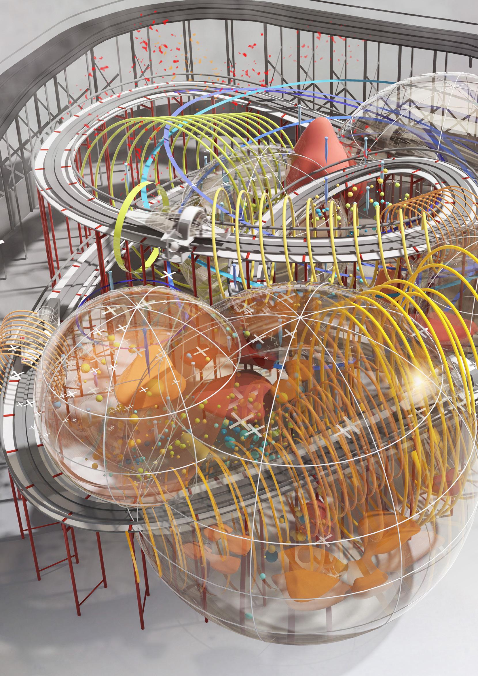
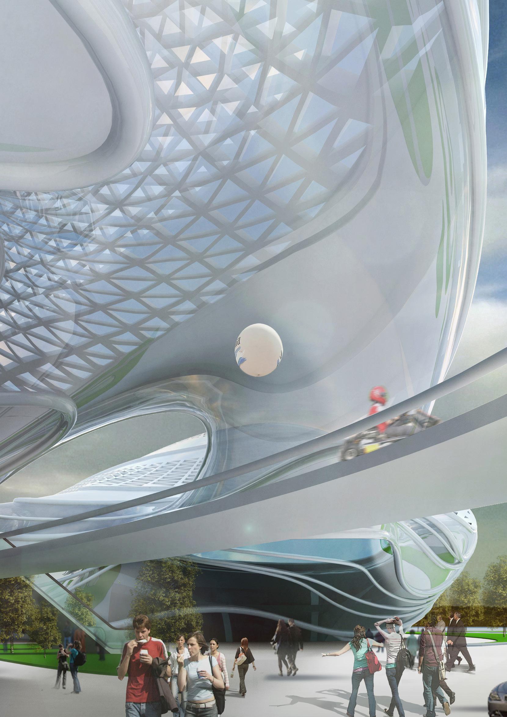
There are four key hospital spaces being regenerated: Carousel (Entrance & Waiting Area), Ferris Wheel (Consultation Rooms), Tunnel World (Corridors) and Spaceship (Diagnostic Imaging Space).

19%

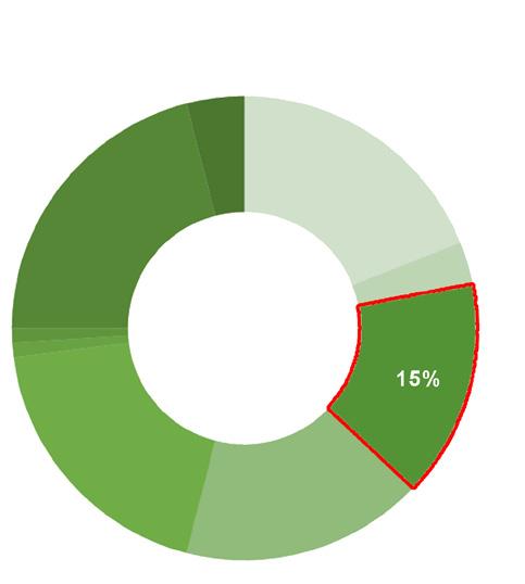
of total population aged under 15 years in Australia in June 2006.
5.2Million
children are predicted to increase to by 2038. The number of children has increased over the past four decades.
24% of Australian children lived in Victoria in 2011.
261,930
times in 2013 of children aged between 5 -14 around Australia were admitted to hospital.
466,379 days for all the children spent in hospital totally.
18%
of children had visited a doctor in the two weeks prior to interview, compared with 25% of the adult population.
41%
of children aged under 15 had a long-term health condition in 2004.
Asthma
is the most commonly reported medical condition, which affects 16% of all children.
0.53%
of infant mortality shown a continuing and appreciable decline during this century.
HIGHEST
RCH received existing system
36,000 children and about
147Billion dollars spent on health care, which takes up 10% of Australia’s GDP in 2012.
52%
of children had used medication during this period, compared to 75% of adults.
1106 children aged 1-17 died, with half attributable to accidents, poisoning and violence.
Some researches have been undertaken in relation to the current health condition of children in Melbourne and the whole Australia. The research shows “this generation of people should be the healthiest ever” and “Australian children are the healthiest group in the population overall”.
Royal Children Hospital (RCH) as a hospital design exemplar is one of the best paediatric hospitals in Australia in terms of its high level of medical facilities, hospital environment, patient experience etc. It’s been doing so well but we do want to find out where it can be improved further. Therefore, the attention shifts from “what makes patients happy” to “what makes patients not happy”. According to the research:
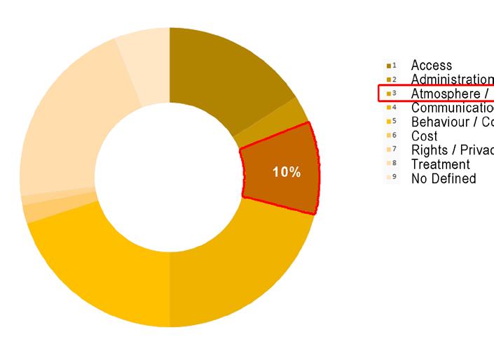
479 complaints
Received in 2013, which arrange from access and administration to hospital environment and atmosphere.
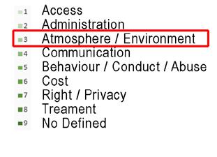
Complaints Received July 2012-June 2013
240,000 of children of the RCH
Complaints Received July 2013-June 2014
HIGHEST level
received the highest awards under the system according to the Healthcare Standards accreditation.
CONCEPT DEVELOPMENT
Current research suggests that the fear of procedures ranks most highly among the concerns of children in hospital. Therefore mitigating the emotion of fear or shifting children’s attentions is becoming a primary solution for the hospital designers and administrators.
Normally in hospital design...
Insert Distractions
36,000 stayed at the hospital overnight, about 200 received care in RCH in 2012.
240,000 children attended appointments at Specialist Clinics 2013.
83% RCH satisfaction rating in the 20122013 period.
Designers would just simply insert kinds of distractions into hospital space to make it “look more interesting”.
But Is there any possibility to do it differently? How about a little twist on this traditional manner?
How about to do it...CONVERSELY!
Insert Hospital Functions
Complaints Received
July 2011-June 2012
Let’s insert hospital functions into a real theme park, and turn that theme park into a real Paediatric Hospital!
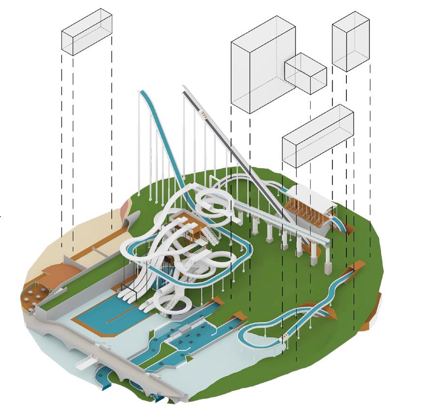
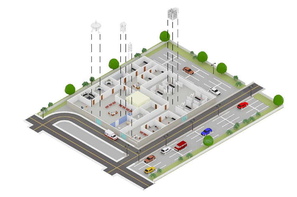
Insert Hospital Functions
Insert Distractions
TransportationGearng
CableCars
CableCars
VerticalTransportation
Carousels(TypeA)

BubbleBalls
Carousels(TypeB)
Atrium

StructuralColumns
BubbleBalls
WHY CAROUSEL?
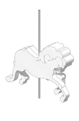
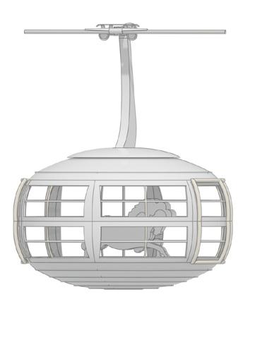
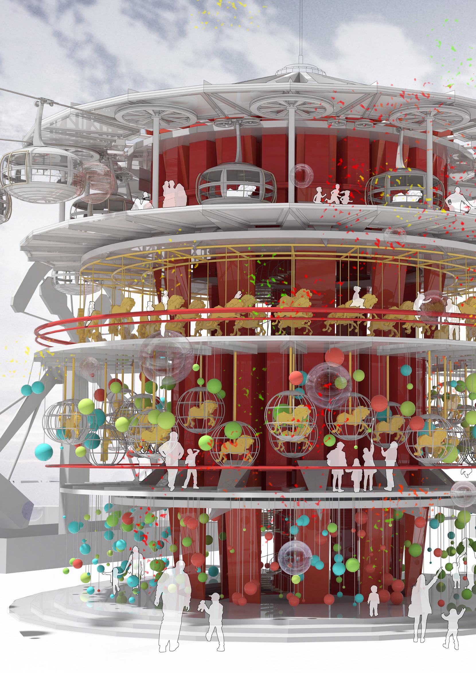
In this project, Carousel contains the Entrance of the Neverland Paediatric Hospital, which allows all kids who are both unwell or healthy to get in and have fun. Here, patients will not have a feeling of fear, being treated discriminatory or socially isolated as the feelings for kids would just be the same as that in a normal theme park without any differences.
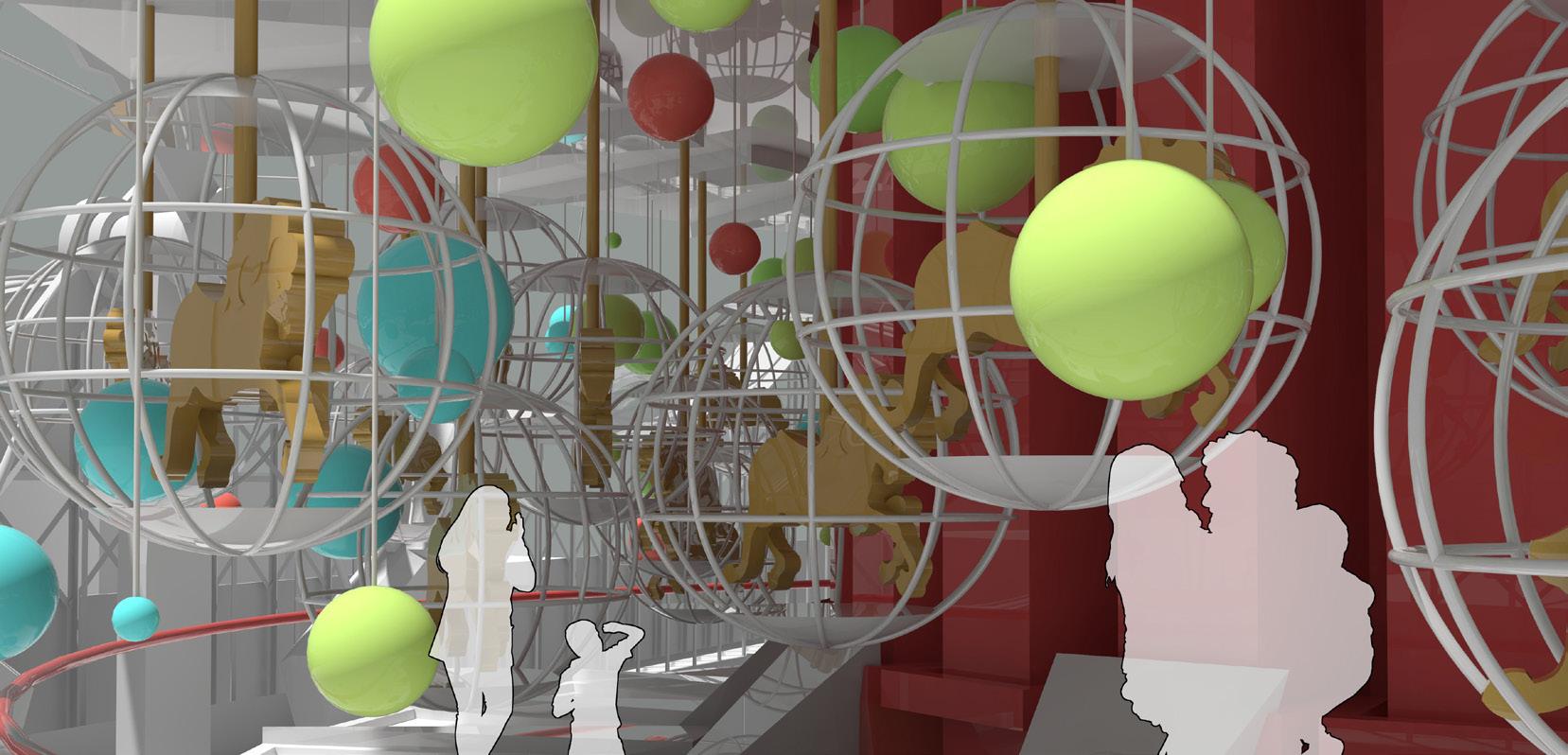

In the Carousel there are four stories. The first three stories are normal Theme Park Carousels that everyone is welcomed to play at. The fourth floor is actually Cable-car Stations, in which patients can take their own “gondola” to other hospital facilities to receive diagnosis and checks. Each cable-car is like a small Waiting Room with one distinguished carousel that will bring sick kids to their destinations.
From the very beginning of their journey in the Neverland Hospital, children will have a totally evolutionary, fearless and interesting medical experience.
Carousels are placed in cable-car carriagesCAROUSEL DECONSTRUCTION
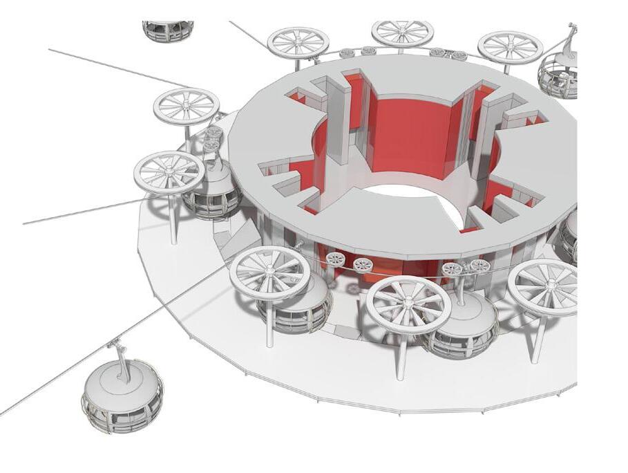


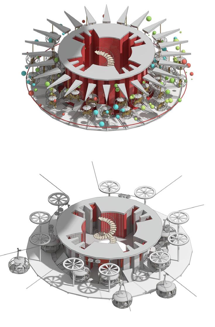
Unwell kids are sent to their destinations in cable-cars
The Fourth Floor of the Carousel plays like a Central Station of the Hospital that is linking to other hospital departments at different locations in the Neverland,
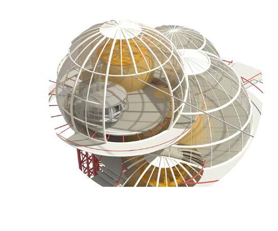
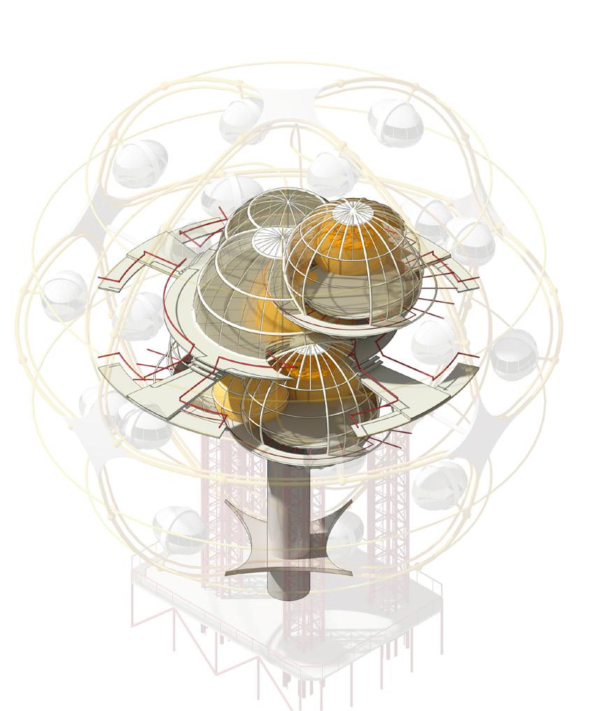
SKY-DREAM FERRIS WHEEL Consultation Rooms
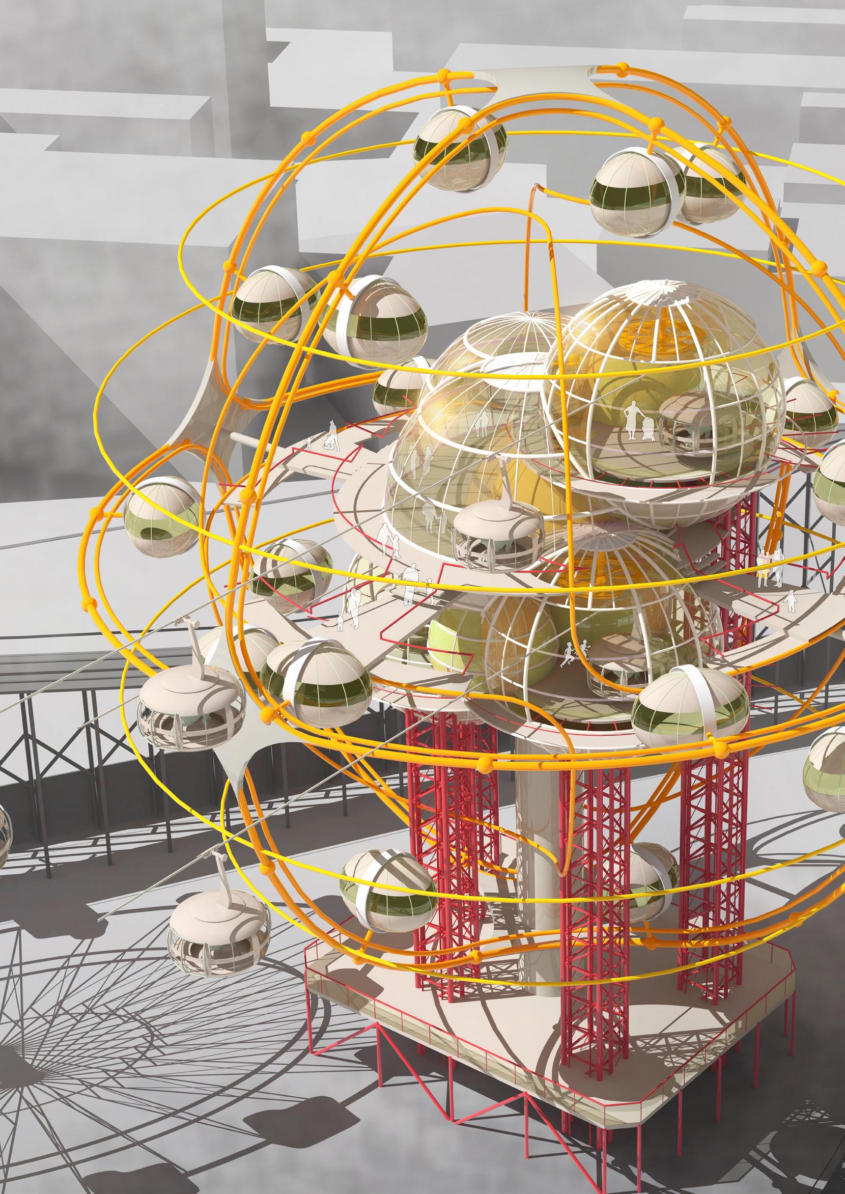
FerrisWheelStructure
FerrisWheelStructure
StationPlatforms
GlazingDomes

CentralAtrium
FerrisWheelStructure

CableCars
CableCarStation
VerticalTransportation
StructuralColumns
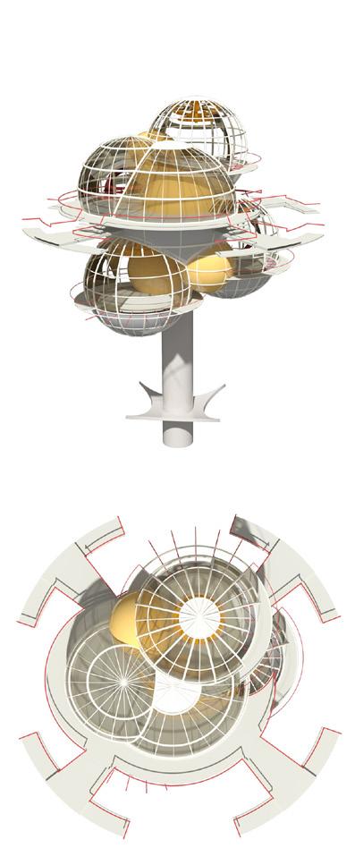
WHY FERRIS WHEEL?
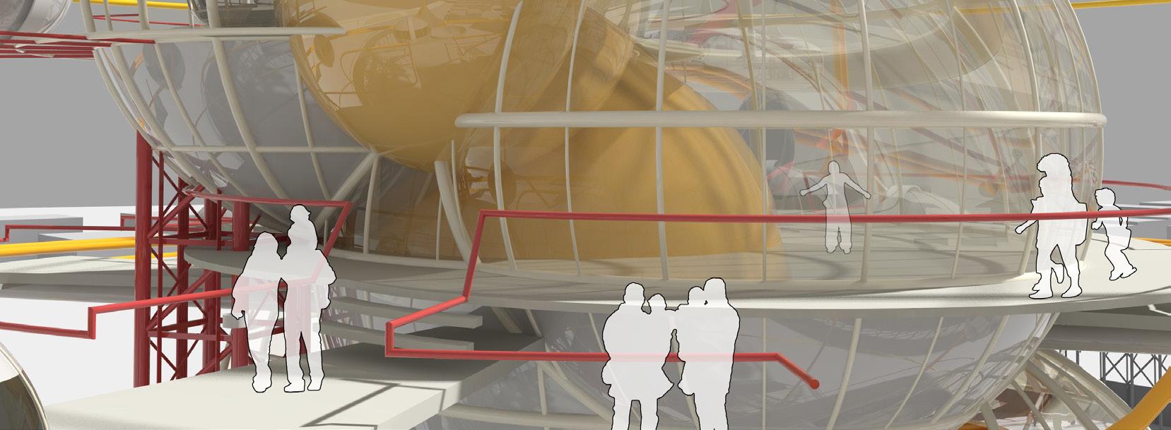
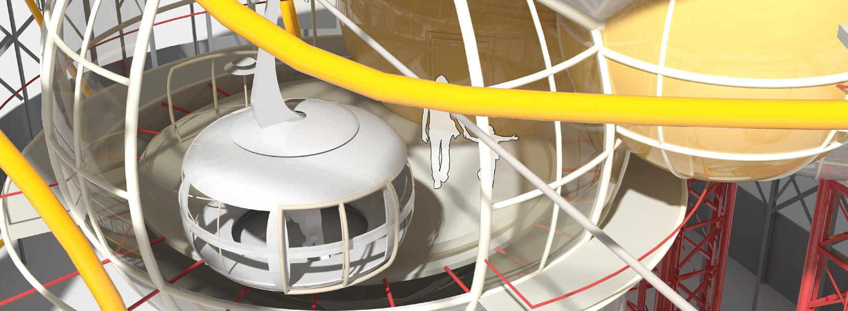
Normally, carriages of Ferris Wheel locate high in the sky that makes them relatively separated from the rest of rides. This feature provides a potentially silent environment which can also avoid cross-infections between patients and healthy children. Moreover, children will have a very good view to surroundings upon the Ferris Wheel so that children’s panic will be significantly relieved.

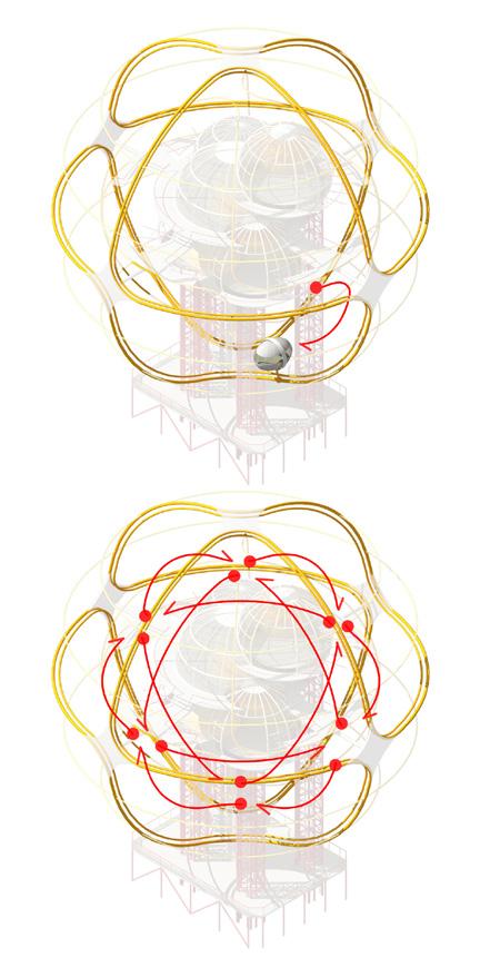
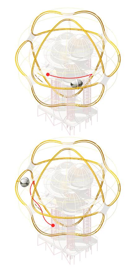
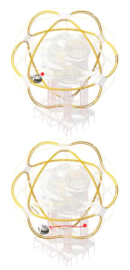
3-DIMENSIONAL CARRIAGE TRACK
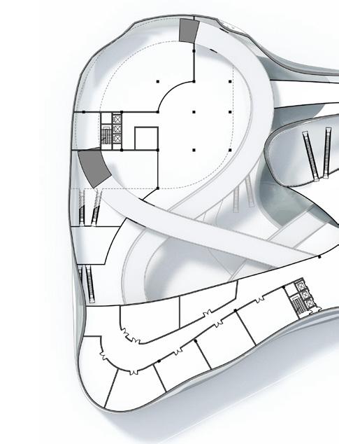
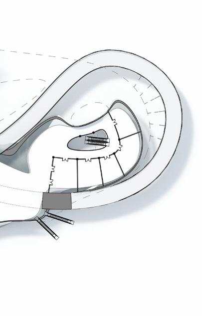
Central Atrium & Reception Staff Office & Storage
Ferris Wheel Platform 4
Ferris Wheel Platform 1
Cable-car Station
Ferris Wheel Platform 3
Access from Ground Level
Ferris Wheel Platform 2
Vertical Transportation
Ferris Wheel Platform 5
Cable-car Station
Access via Cable-car Station
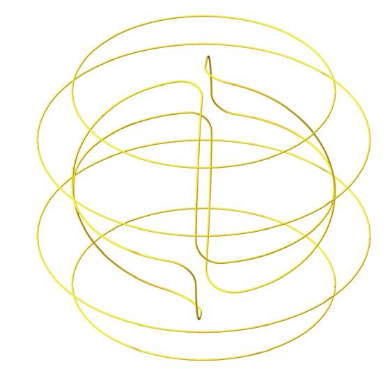
Different from other traditional ones, this Ferris Wheel equips a 3-dimensional track along which 24 carriages are able to run continuously all the way around. One of the hardest parts of combing a traditional Ferris Wheel with Consultation Rooms is that the time for carriages spinning around Ferris Wheels is fixed and inflexible, but a doctor consultation time is quite flexible which mostly lasts from about 5mins to 15mins.
To resolve this issue, a 3-dimensional track is designed along which carriages are able to go pass one of the five platforms in every 5mins and it decreases interval time and increases consultation efficiency significantly
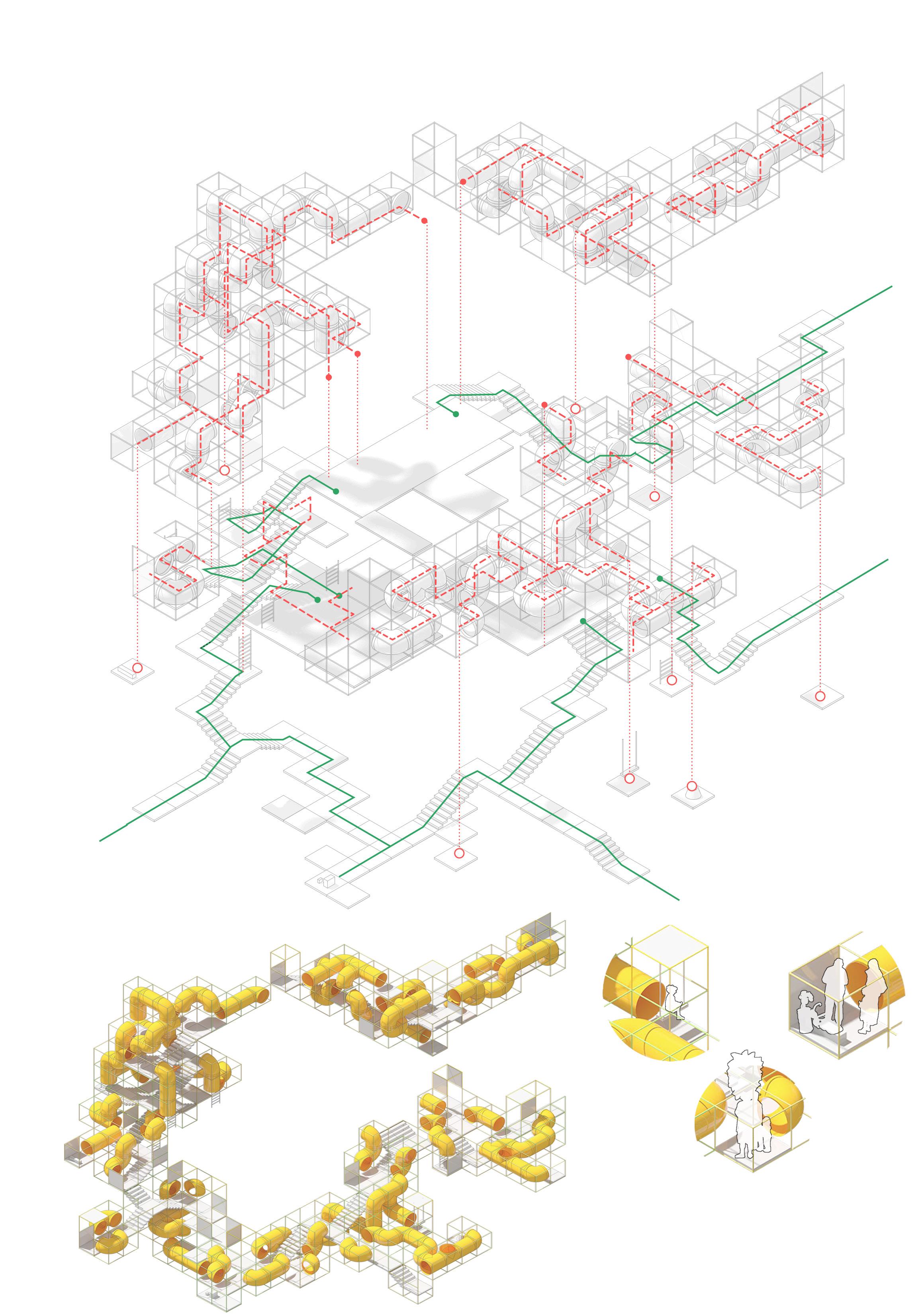
TUNNEL WORLD Corridors
TunnelPathways
Walkways
TunnelStructure
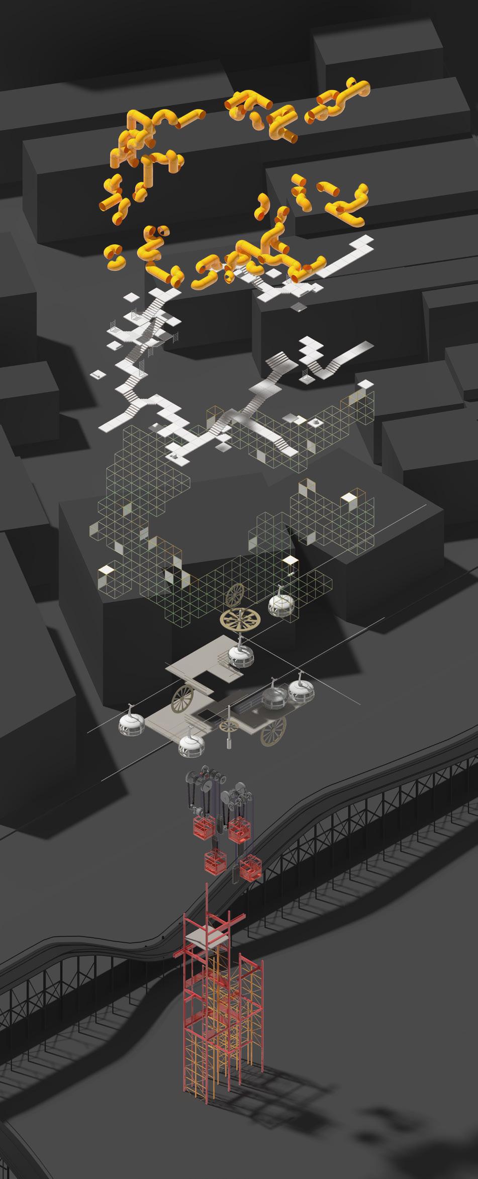
Cable-car
TransportationGearing

Cable-carStation
VerticalTranspiration
Structure
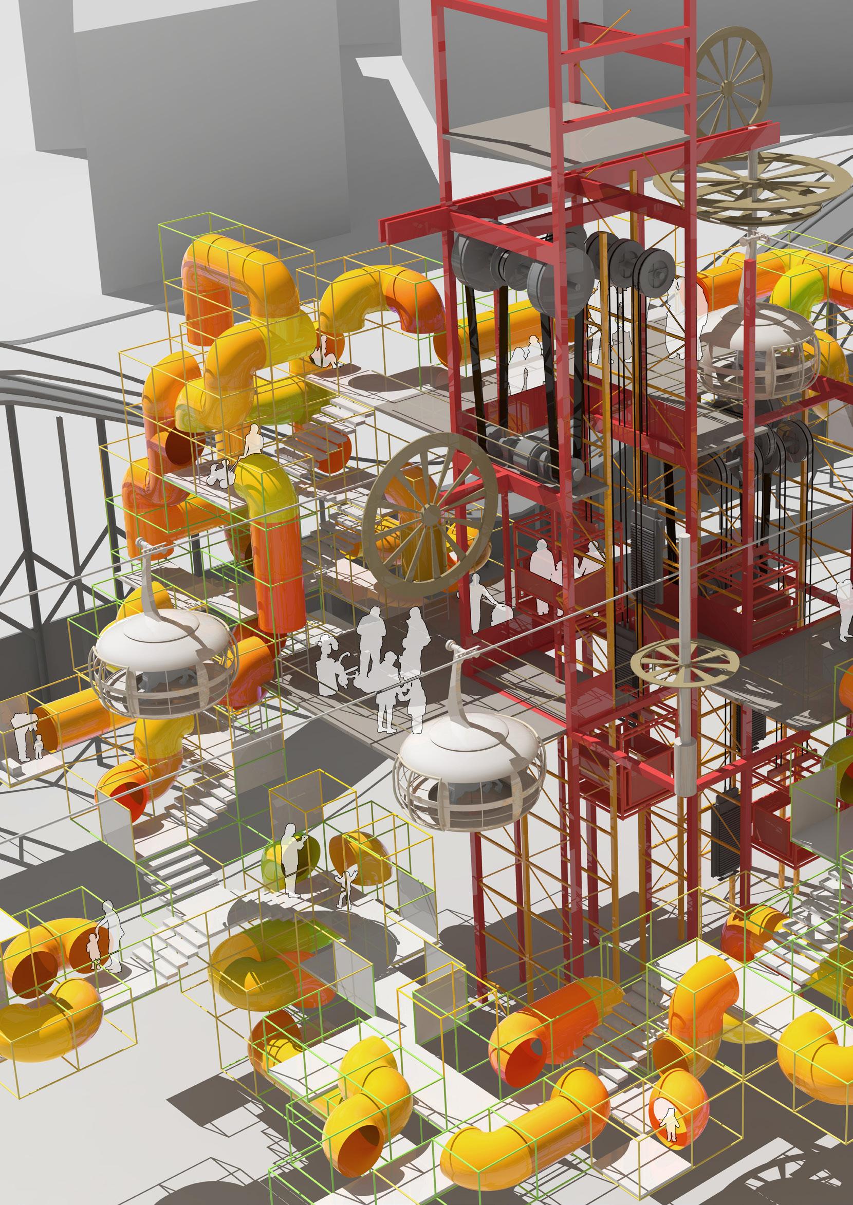
WHY TUNNELS?
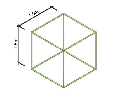
1.5 meters is a magic scale. The Tunnel Corridors apply 1.5 meters as a typical length to create tunnels and the structural cube frames since it is just a proper scale for children. Kids are able to jump in and out of 1.5 meter high tunnels easily, while adults may have to bend down a little to get in. Curiosity is the nature of children. These tunnel pathways are like special corridors specifically designed for kids in which they can play and explore around just like taking adventures.

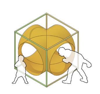
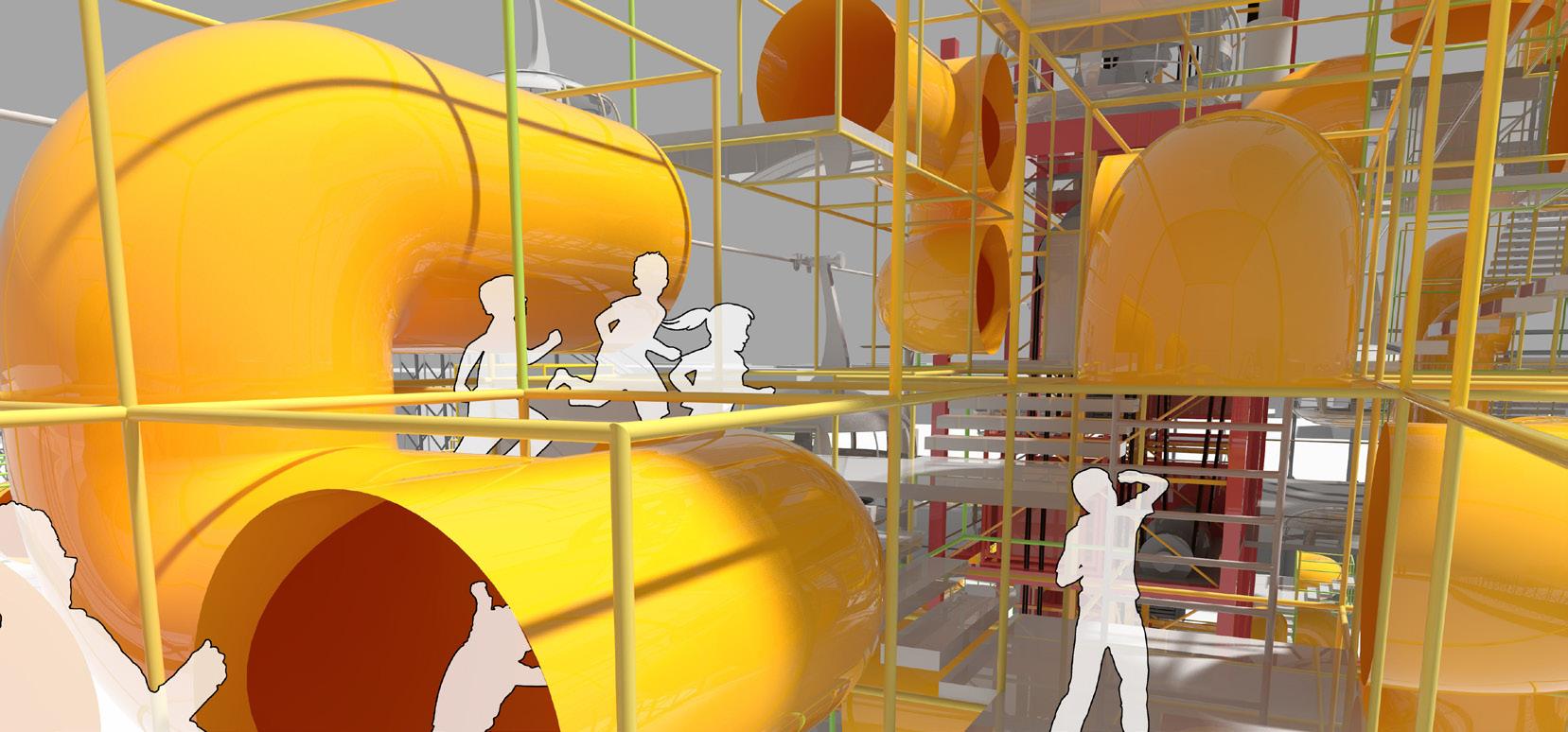
In the Tunnels there are some Secret Spots. When kids are exploring the Tunnel World, they will have some unexpected experiences, for example, they could find a cartoon sculpture, a swing, or even get free candies and balloons from hospital staff who are dressed in costumes.
SPACE FORCE
Diagnostic Imaging Space
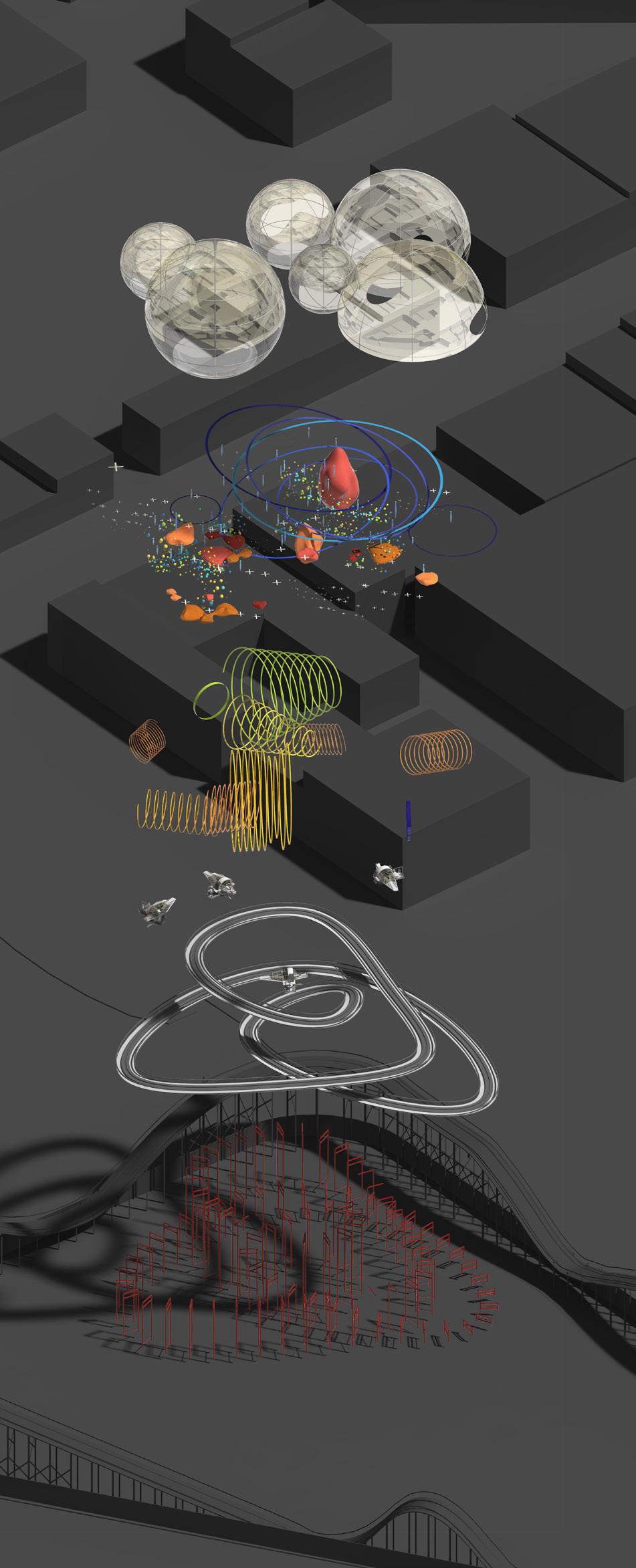
GlazingDomes

SpaceForceType1
AdventureSetup
SpaceForceType2
RollerCoasterTrack
Structure
WHY SPACESHIP?
The idea is to move X-Ray inspection machines and MRI scan machines out of their traditional “Diagnostic Imaging Rooms” and place them on an unexpected location - a low-speed Roller Coaster which brings kids a brand new experience.

There are two types of spaceships in the ride. The Space Force ship type 1 are combined with X-Ray machines, while the Space Force ship type 2 are combined with MRI machines. On each space ship, it also contains a Doctor Control Centre where doctors can sit and control the scan work. This way, getting imaging tests is no longer a scary process for kids but becomes a brand new journey.
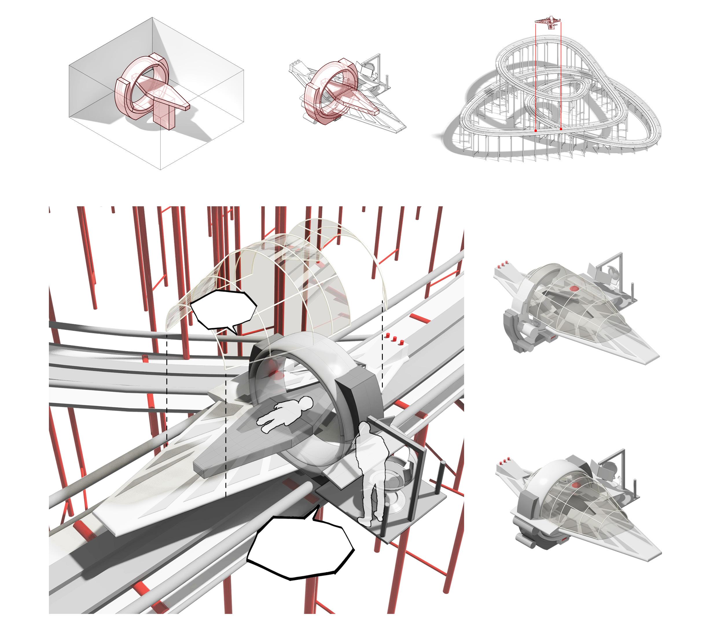
Low-speed
Are you ready to take a big adventure with me?
Space Force - Type 1
Space Force - Type 2
Combined with X-Ray Inspection Machine Spaceship Diagnostic Imaging Scanner Roller Coaster Combined with MRI Scan Machine AyeAye, Captain!WHY SPACESHIP?

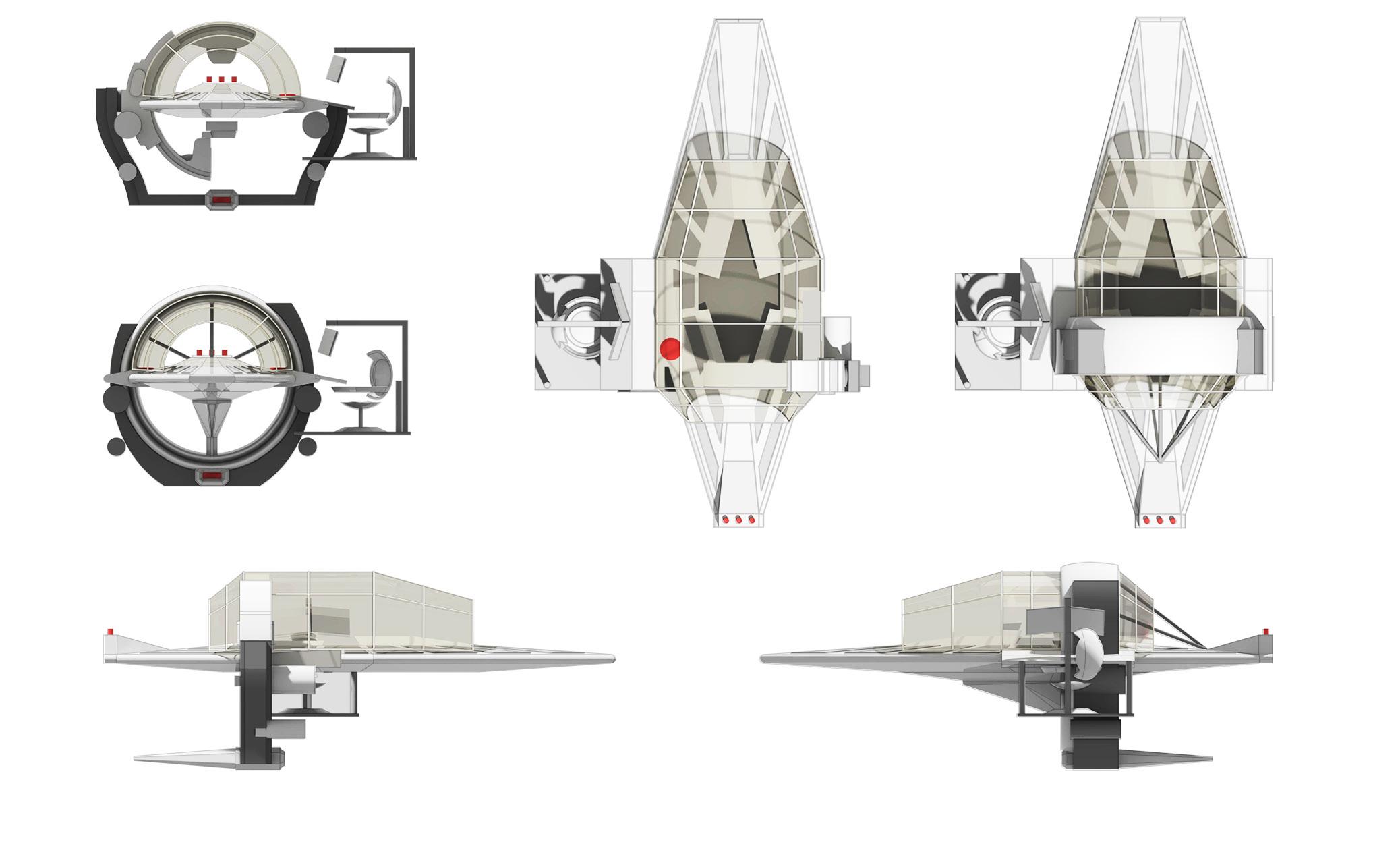
 Space Force - Type 1 Front Elevation
Space Force - Type 2 Front Elevation
Space Force - Type 1 Front Elevation
Space Force - Type 1 Front Elevation
Space Force - Type 1 Front Elevation
Space Force - Type 2 Front Elevation
X-Ray Inspection Machine
X-Ray Inspection Machine
Glass Shelter Glass Shelter Doctor Control Centre
Doctor Control Centre
Patient Bed
Patient Bed
Spaceship Base
Spaceship Base
Space Force - Type 2
Space Force - Type 2
Space Force - Type 1 Front Elevation
Space Force - Type 2 Front Elevation
Space Force - Type 1 Front Elevation
Space Force - Type 1 Front Elevation
Space Force - Type 1 Front Elevation
Space Force - Type 2 Front Elevation
X-Ray Inspection Machine
X-Ray Inspection Machine
Glass Shelter Glass Shelter Doctor Control Centre
Doctor Control Centre
Patient Bed
Patient Bed
Spaceship Base
Spaceship Base
Space Force - Type 2
Space Force - Type 2
The site is currently a Carpark in the west-north of Melbourne City, bordering the famous and historical city attractions Queen Victoria Market to the north-east and Flagstaff Garden to the south-west.
The local council wants to make a better use of existing Carpark by constructing a new iconic landmark on site that will as a result stimulate the local economy and also satisfy the increasing requirements of local residents and tourists.
According to the course requirements, besides the essential functions that need to be provided, e.g. Retails and Restaurants, proposed design should also include some unexpected new functions, such as an Indoor Swimming Pool, Bicycle-running Loop, Rock-climbing Walls, etc.

TORIA
Urban Complex Design
Studio Design Work
2015, Semester 2
The University of Melbourne
Site: Melbourne, Victoria, Australia
Tutor: Dominik Holzer
Individual Work
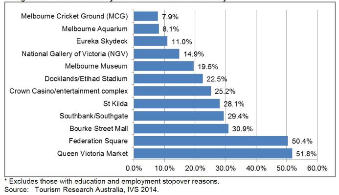
Places Visited by International Visitors to Melbourne
Mode of Travel Used to Get Around the City of Melbourne
Places Visited by Interstate Visitors to Melbourne
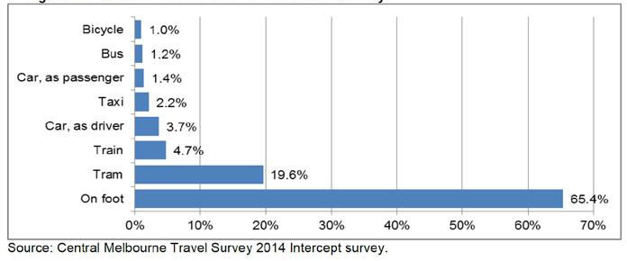
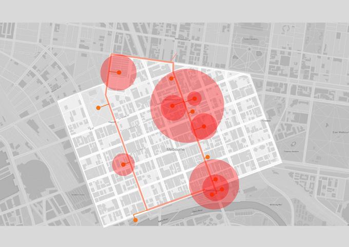
Research shows that walking is the most preferred mode of travel to get around the city. About two third of people would prefer to travel around the city on foot.
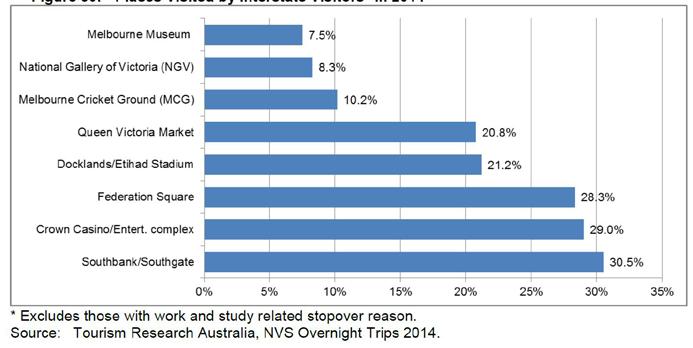
According to the Surveys by City Council in 2014, Queen Victoria Market which is right adjacent to the site is one of the most favourite attractions in the City of Melbourne.
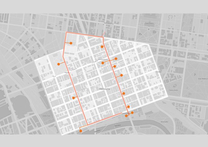
The orange path shows a typical day-tour routine of the Melbourne City. Following the route visitors are able to go through and visit most of the city icons. This path also goes past the project site.
The iconic QV Market is right next to the project site. Constructing a new city landmark there will also help increase the influence and attraction of QV Market.
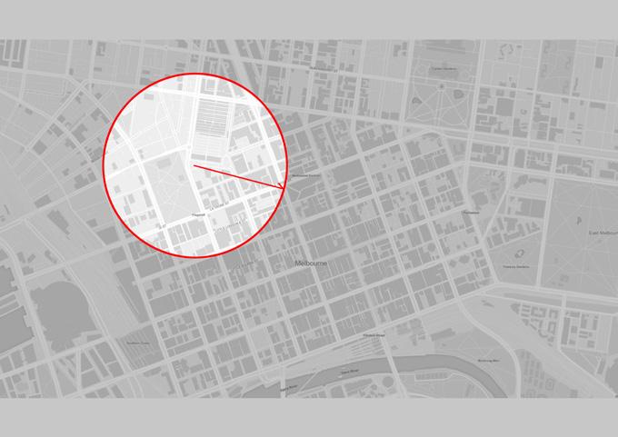
Since walking is the most preferred mode for people in the City, drawing a 500m radius circle that indicates a walking accessible scope within which people are able to approach to on foot in 10 minutes.
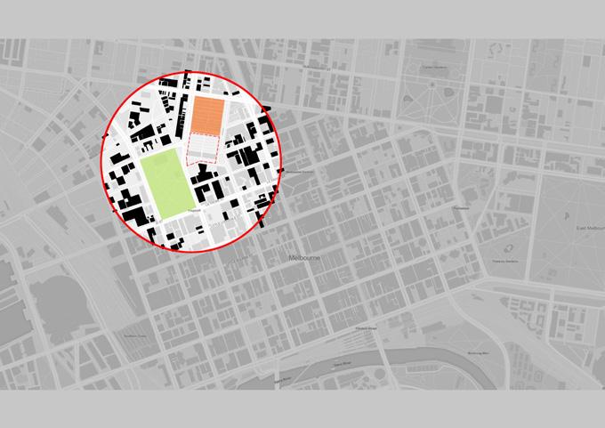
Within this circle, the black blocks represent residential buildings. The site is located in-between QV Market and Flagstaff Garden, the most historical market and garden in Victoria.

Together with the nearby Flagstaff Garden and QV Market, a new commercial complex that is set up on site will significantly enhance the influence and attraction of this area and even of the whole city
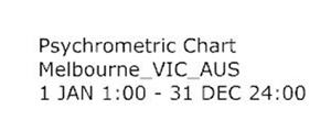
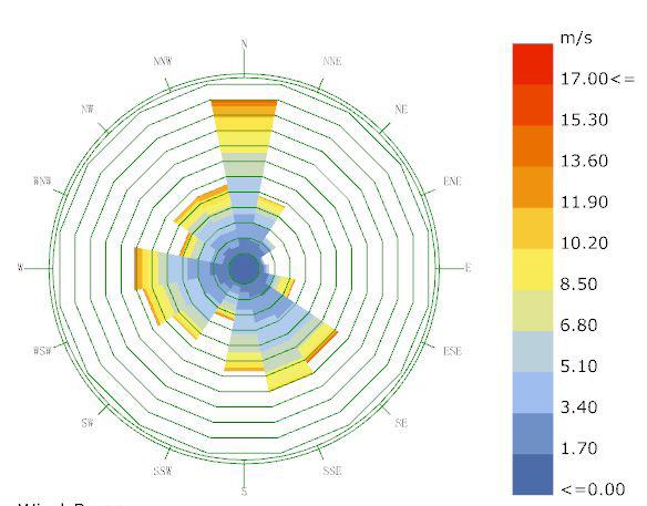
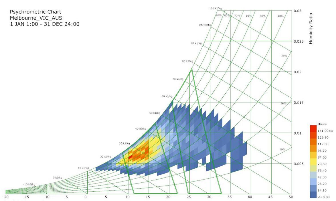
CLIMATE ANALYSIS
There are mainly north winds and some south-eastern winds all year round, although humidity is overall mild. The temperature between day and night changes dramatically. Especially at noon time of Summer, when sunshine is very strong, it would be over 30 °C on average and good to have some sunshades for for those who are staying outdoor on site.
Dry Bulb Temperature (C) - Hourly
Dry Bulb Temperature (C) - Hourly
Dry Bulb Temperature (C) - Hourly


Wing-Rose
Hourly Data: Wind Speed (m/s)
Dry Bulb Temperature
Total Radiation(kWh/m2)


Diffuse Radiation(kWh/m2)
Direct Radiation(kWh/m2)
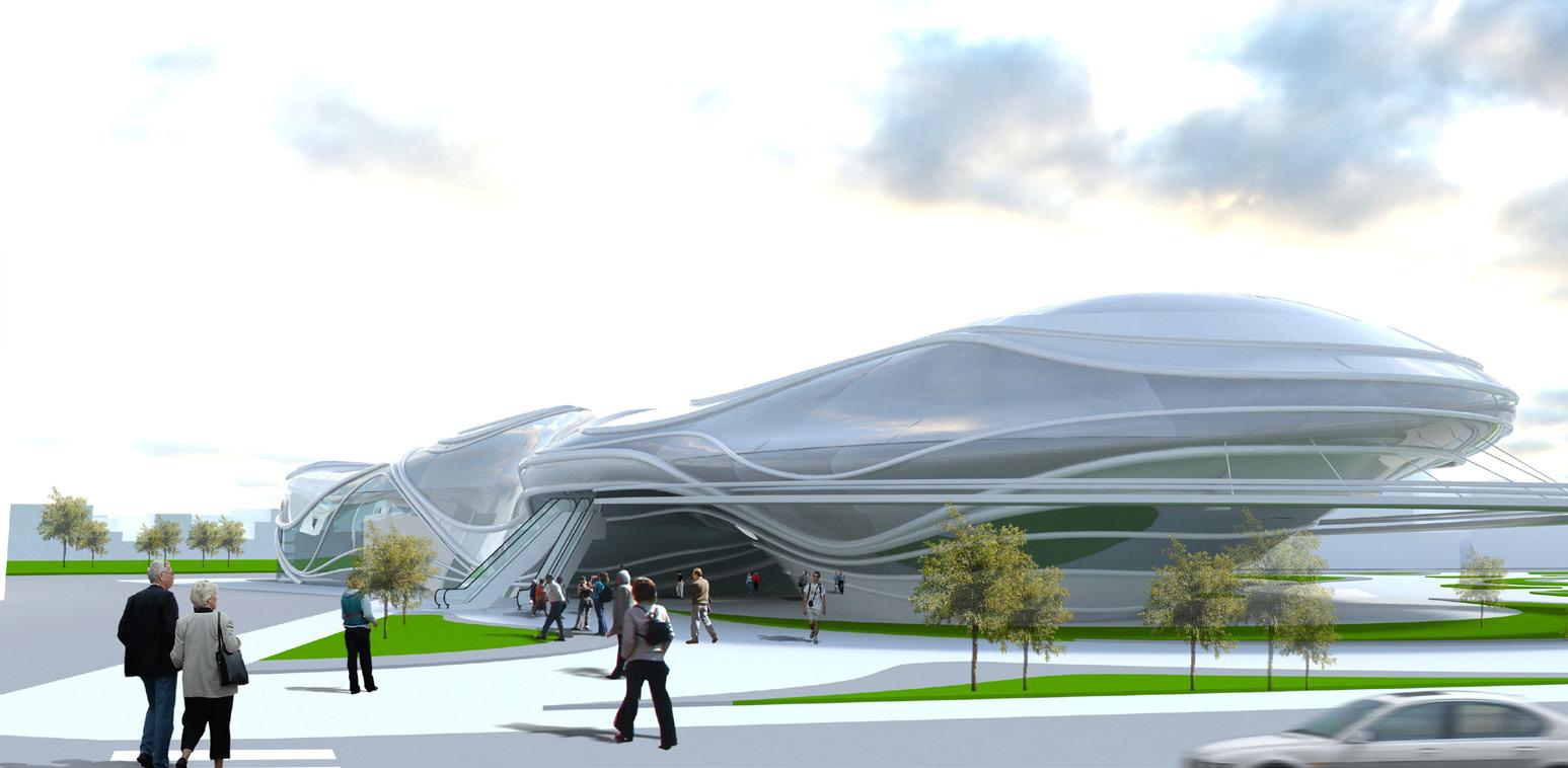
The project aims to, not only create a new landmark building in-between the QV Market and Flagstaff Garden, but also play as an important connection linking these two iconic places so that all three icons can be joined together as one producing a more significant influence on the area.
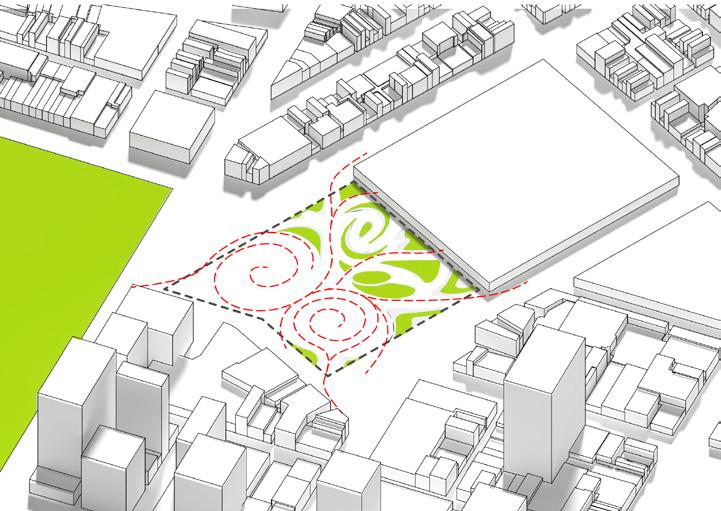
The proposed building is like powerful vortexes to which more customer flows are attracted and swarming into. As people flows join together or vary orientations on site that divides the site into different sections, that becomes the initial shape of the site landscape.
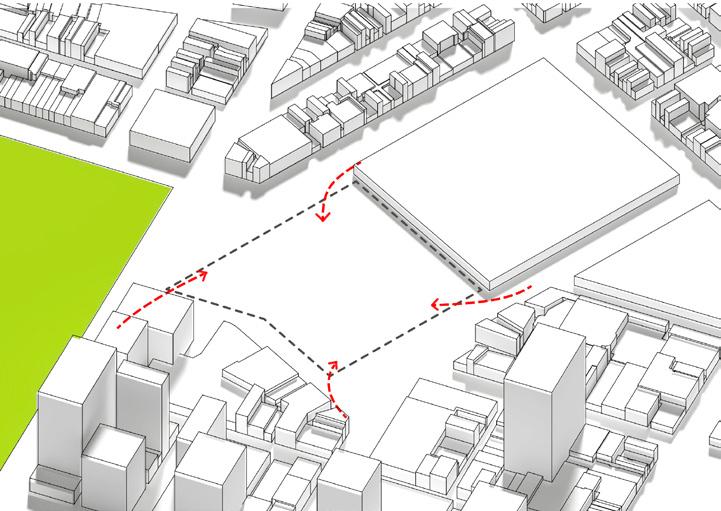

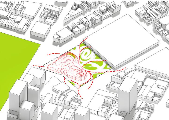

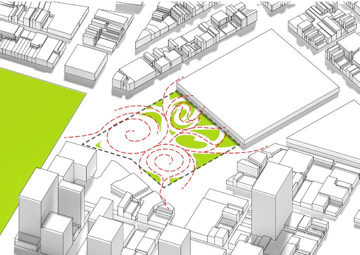
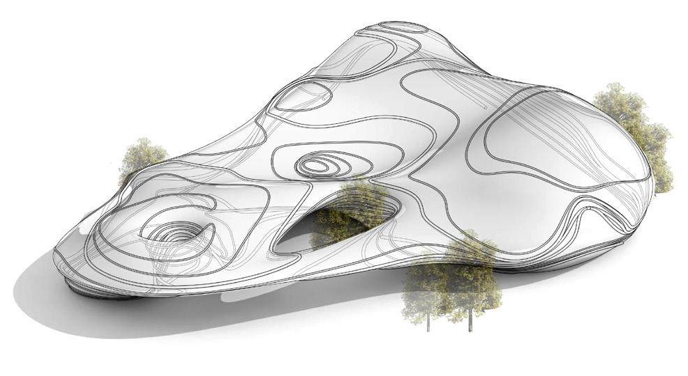
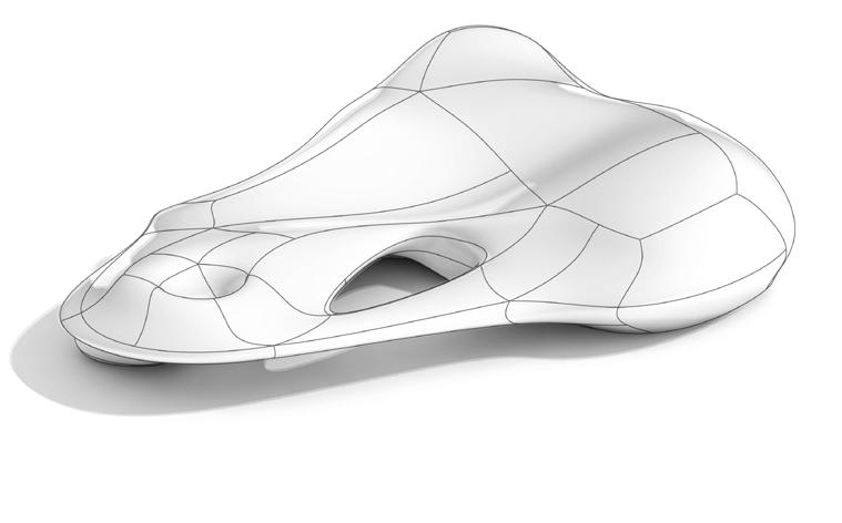
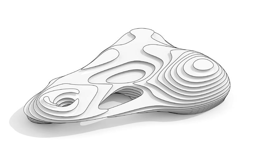
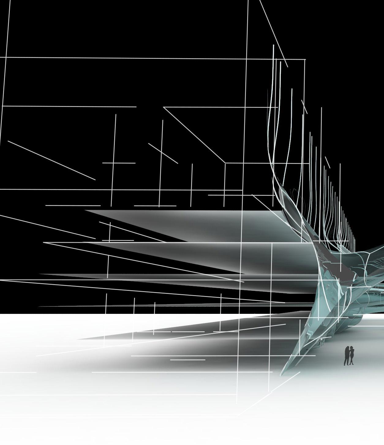
Lift the vortex contours up. Under those ascended contours some new spaces are generated. Adjust and Loft those ascended contours then a preliminary form of the building emerges.
FORM & FACADE OPTIMISATION
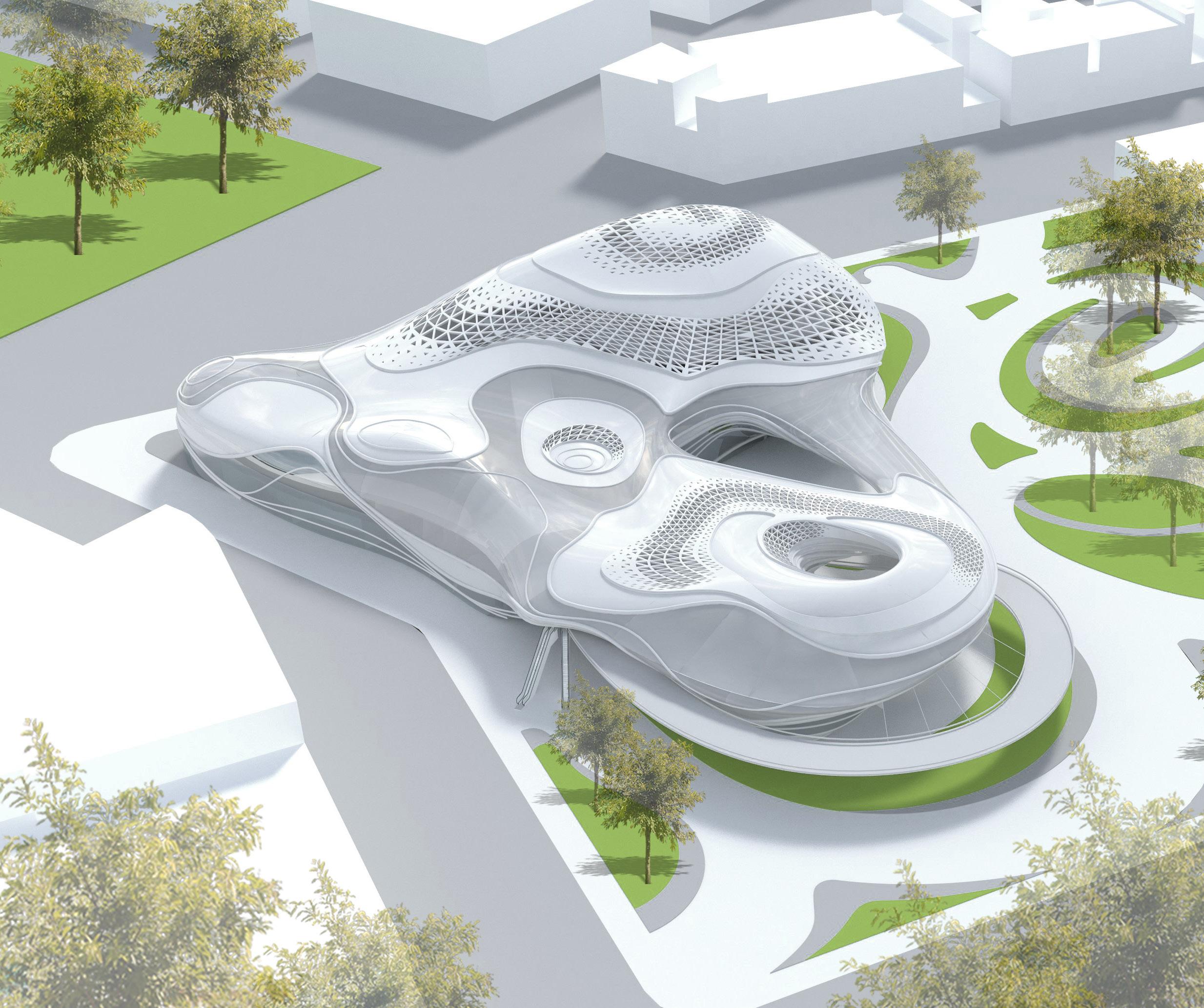
Apply parametric tools to create a more dynamic form which is also able to fulfil functional requirements of the building screens and internal spaces.
Vertical Transportation
Vertical Transportations
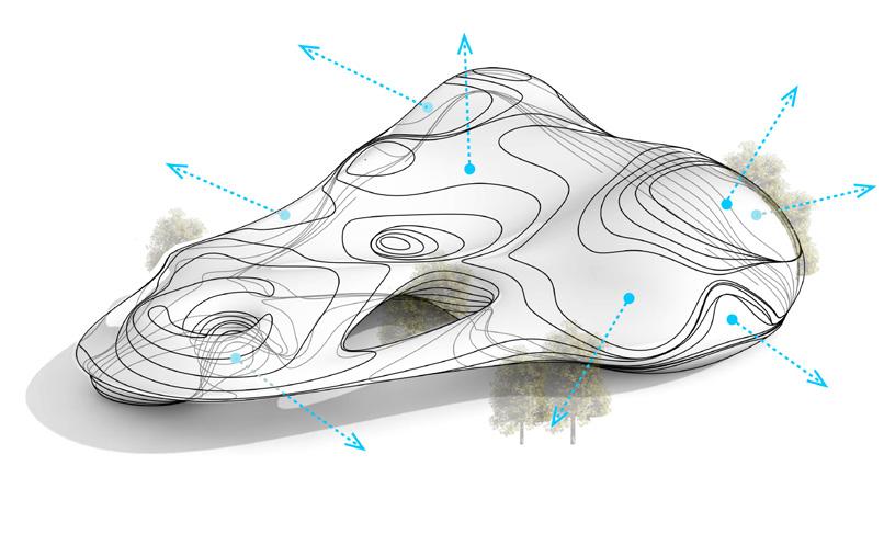
According to the different requirements of internal functions, twist the ascended contour lines to have them become looser or denser. For those which need better sunlight conditions, apply looser contour lines , which will introduce more natural light and also create better views for the users inside.


ROOF DECOMPOSITION
Perforated Aluminium Panels

ROOF DECOMPOSITION
East Elevation
Coated Glazing
Steel Truss


Structure
Ceiling Roof Surface

DudleyStreet
WilliamStreet
Franklin Street
North Elevation
South Elevation
Peel Street
3D PERSPECTIVE SECTIONS
According to course requirements, the proposed urban complex project should include some main functions of Retails, Restaurants, Exhibition Space, Spa Centre, Multi-function Rooms alone with other functions like Rockclimbing Walls, Bicycle Track and Indoor Swimming Pools.
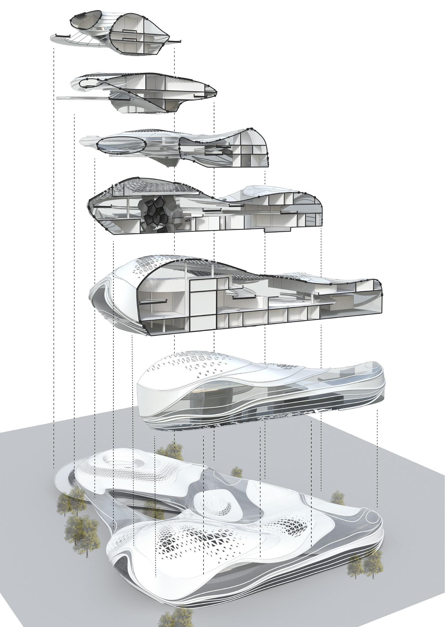
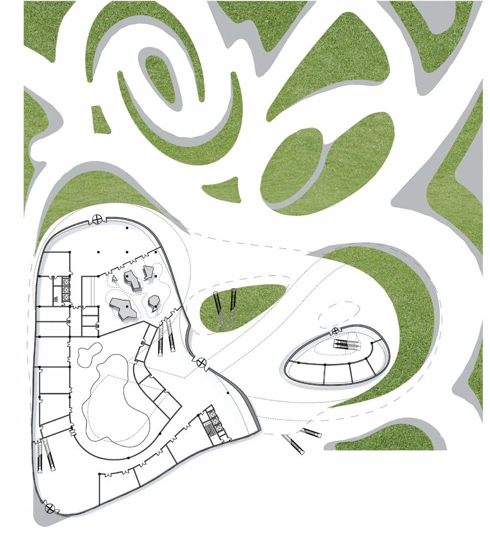
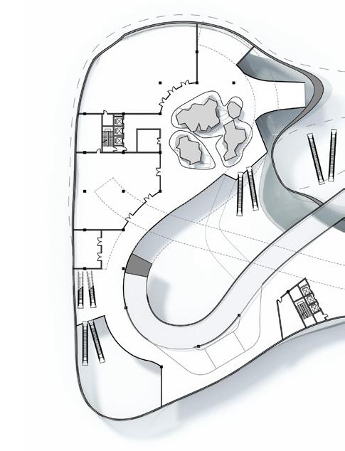

Aluminium Panels with Perforated Triangular Patterns
Facade and Structure
Coated Glazings
Bicycle Track
3rd Floor
2nd Floor
Rock-Climbing Blocks
1st Floor
Ground Floor

Structural Columns


Outdoor Landscape

Pudding City
Computer-aided-design Simulated City
Studio Design Work
2015, Semester 1
The University of Melbourne
Site: Melbourne City, Victoria, Australia
Tutor: Justyna Karakiewicz
Group Work (Partner: Ye Yang)
According to the course requirements, we firstly are asked to generate a bigger thinking idea of how the future city dwelling will be like especially as an important part of the urban ecological system. In addition to that, we need to select a specific location in the city to produce our dwelling concept, and develop it further to an architectural design idea.
Different to the traditional way that architects normally lead the design direction and decide what cites and buildings should look like, in this project we build a little computer program first instead, have it “informing” us how an ideal city should be developed into. Based on the generated results of the computer program, we then develop it to a proper architectural design.
THE “PUDDING CITY” CONCEPT

Would you prefer a “Salad City” or a “Pudding City”?
Before answering this question, you might be confused as to what a “Pudding City” is? What is a “Salad City”? What is the difference between them then? So, a major difference between salad and pudding is: in a salad, we can always tell every raw ingredient of it, like corns, eggs, tomatoes, etc. even though it has been thoroughly stirred; however, in a pudding, when it’s been cooked properly, with some “chemical reactions” happening inside, all the ingredients lose their original appearances and are merged together and form the shape of a pudding.
When we are proposing an urban design idea, same choice is placed in front of us: in order to satisfy the increasing requirements of city’s development, do we just simply put all necessary functions into the city without enough considerations like making a salad? Or should we draw attention to the compatibility of different functions so that we can make sure those functions can work together well with some “chemical reactions” like making a pudding?
So the concept of this project is to create a “Pudding City”.

We take the City of Melbourne as our scope of research. The Melbourne City consists of different grids of communities and blocks, and it is filled with various types of buildings, such as offices, restaurants, retails, apartments, etc., satisfying the needs of different people from different background.
To some extent, living in city is like having meals by a huge table with all kinds of dishes, people can grab the food they need from this ‘urban feast’. The chefs are urban designers and architects: although we always try to produce best gourmet ‘dishes’ for people, as time goes on, some dishes don’t seem appropriate any more as they cannot fulfil the latest flavour. When one ‘dish’ has turned out to be not attractive any more, chefs sometimes would just replace it with a new one, similar to when urban architects sometimes having to decide to demolish old buildings and set up new ones.
However, facing those old dishes, instead of discarding them, what we are trying to do here is to add some additional ingredients to the current ‘dish’ making it yummy again.
Agent Wandering
PROGRAM CODES OF PUDDING CITY

(Definitions of all the codes will be explained in the next pages)
Agent Home Setting
Destination Setting
Obstacle Avoidance
Agent Value Recovering
Agent Route Finding
Death of Agent
New Cube Generation
Data-output
Simulative City
CHARACTERISTICS OF AGENTS
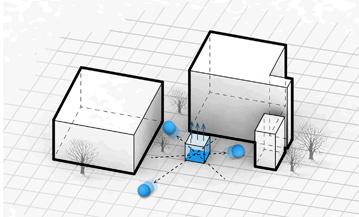
In the early stage, a coding platform called NetLogo is chosen to produce our program. About 5000 intelligent agents are created and put into the simulated city. We hope these agents can act like humans that can feel “hungry” and “tired” and also be able to wander in the “city” finding out proper spots satisfying their basic desires.
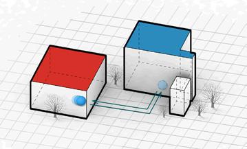
The site we selected is a section of Melbourne City grids and the site to insert new buildings is the gaps between city blocks, which is the space above
Then we decide to set up some new rules into the program so some new additional function cubes will be inserted into the current city to satisfy agents’ urgent requirements that the current city cannot provide. These new cubes will only emerge above the city street areas and not change the current buildings’ layouts and their functions, so that the inserted functional cubes will act like ingredients to optimize our current city.
In the program, we endow some unique characteristics to each agent to make them ‘alive’ like a real person in a real city. Some key indices that we have set up for the agents are as below:
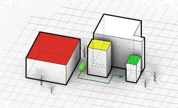
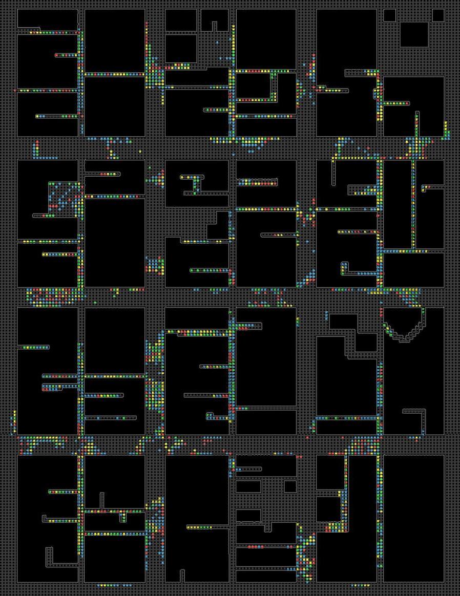
• Pixel colours: different colours represent different functional spaces in the simulative city: red, yellow, blue and green pixels indicate areas for rest, entertainment, work and dining respectively.
• Agent ID: every agent has its unique agent ID.
• Agent Coordinate: in the simulative city, wherever an agent goes, there will be a corresponding coordinate that indicates the location of that agent.
• Rest / Entertainment / Work / Dining: standard indices indicate agents’ degree of desires for having rest, getting entertained, going to work and taking food. All indices will go low with the time flow. When agents stay in coloured areas, the corresponding index will be gradually recovered to up to 100;
• Energy: It is a special index that whatever an agent is doing will consume this number. When the index goes below 20, agents need to go back to their own homes to sleep.
• Agent’s displayed colour: it indicates the lowest index out of all four standard indices of an agent.
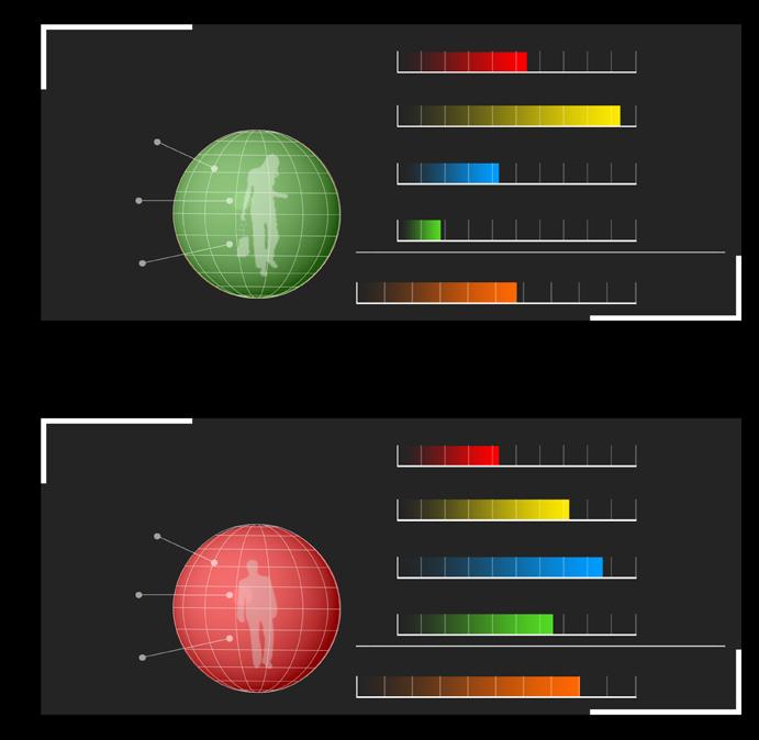
• Desires: when any one of the indices goes below 20, it becomes that agent’s greatest desire, which will make it stop whatever it’s doing and try to go to the closest relevant functional area to have that index recovered.
FOUR RULES TO MAKE AGENTS “SMART” AND ‘INNOVATIVE”
In the Pudding City, in instead of making design decision by ourselves, we use coding to create a simulative city and 5000 intelligent agents, then we set up four rules for them. The agents are therefore able to “live” in the simulative city and “tell” us what they really need:
1. Distance Estimate:
Agents are able to look for their most desirable destinations automatically by identifying the shortest distance.
3. Accommodation & Office:
For every agent we allocate it with a specific home and work place in the city randomly when the program starts.
2. Route Finding:
When moving towards their own desirable destinations, agents are able to intelligently avoid obstacles on their way.
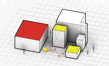
4. Power to Create:
When any five agents walk across the same pixel with a same desire, one new functional cube will be generated on that pixel accordingly.
CONTEXT SET UP AND RUNNING RESULT RECORD
10 (50m)pixels
10 (50m)pixels
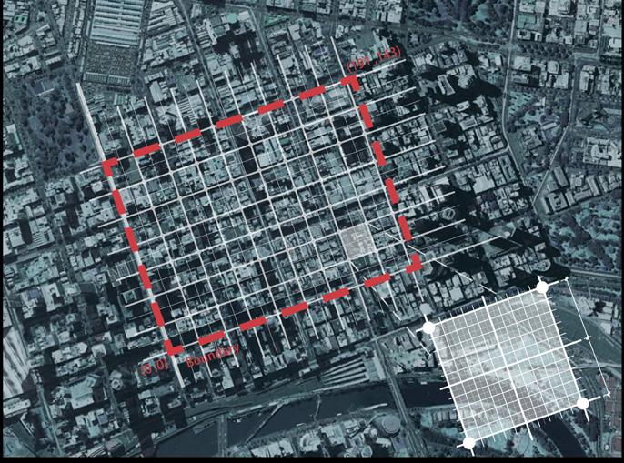
Selecting part of Melbourne City area as the scope to generate the Simulative City. Dividing this area by 200*150 meshes, and each mesh is regarded as one pixel, the size of each pixel is then about 5m*5m.

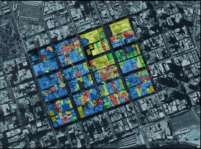
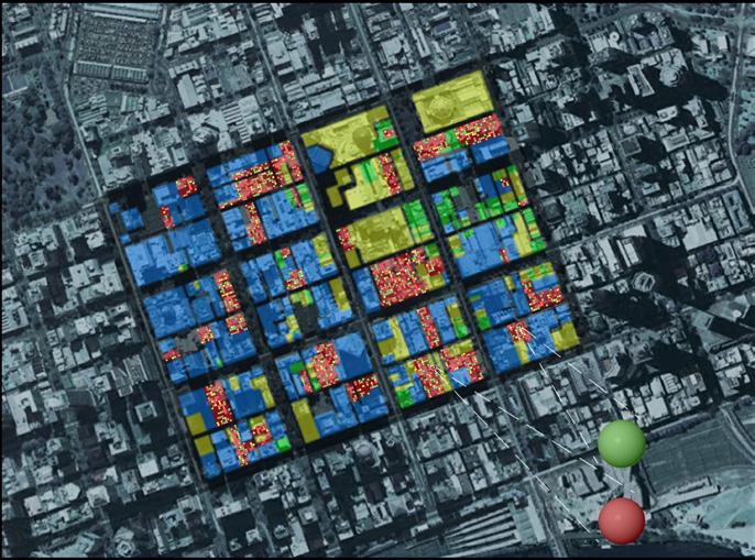

Abstracting all existing buildings in the selected area and categorising them into four main functional areas: rest, entertainment, working and dining.
Agent
Agent
By calculation, there are 3600 pixels in colour ‘red‘ that represents the area of ‘homes’. Allocating those homes to 1800 agents so that every single agent has its own two pixels home.
Running the program and all agents start “living” in the simulative city.
Stop the system and record the final result.
In the results, some new functions have emerged amongst the existing buildings, which are generated based on agents’ living requirements.
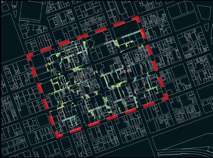
SYSTEM RUNNING RESULT
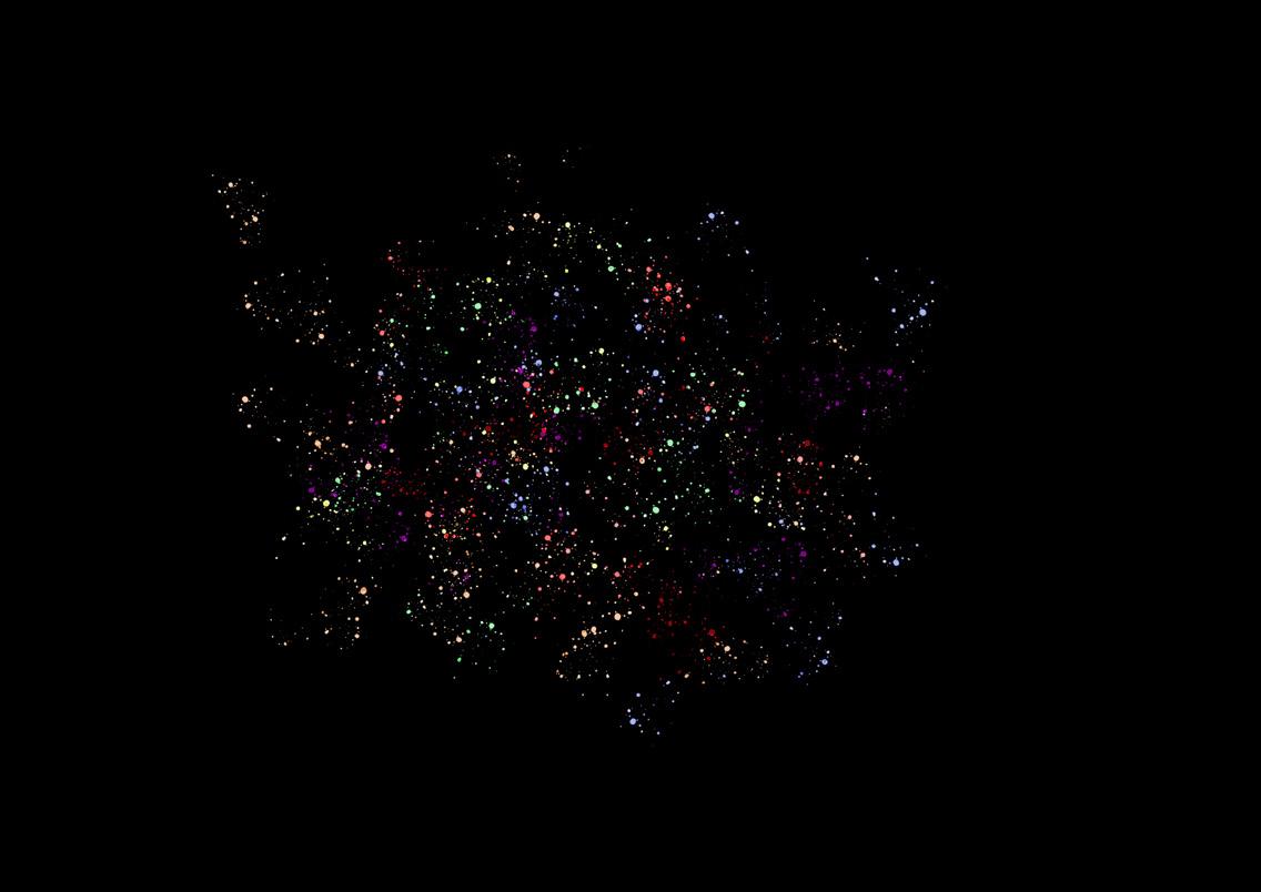
Now in the simulative city, new colour pixels are generated amongst the existing buildings. All of those are new functional areas proposed by the agents who are actually living in the city.
(0,150) (0,0)
(200,0) X
(200,150)
analyseSelectfourconnectedblockareasto theirfunctionalcomposition
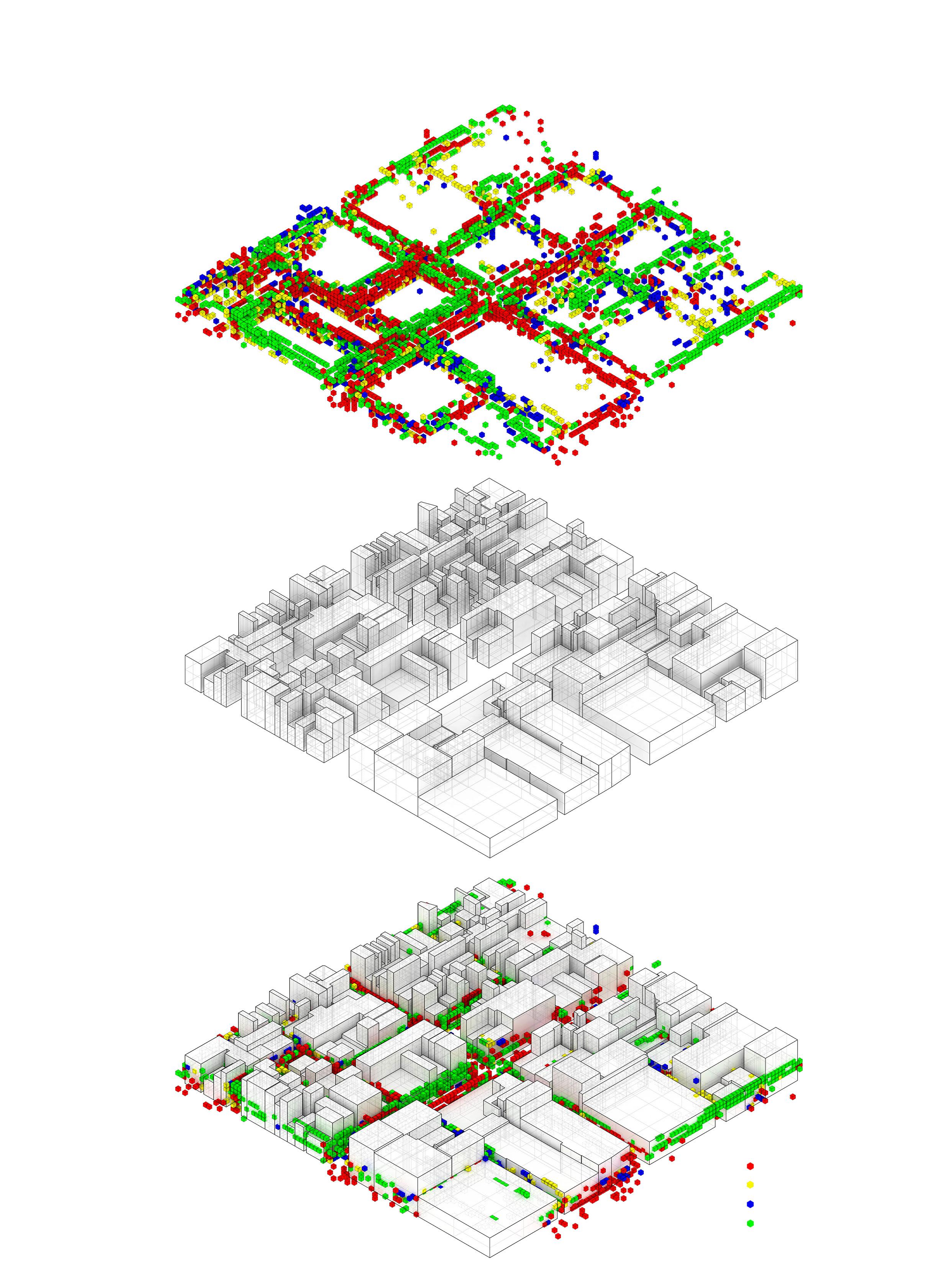
Computer-generatedFunctionalCubes
Existingbuildingsblocks
selectasectionofonestreetto producefurtherdesigndevelopment
Entertainment Space
Rest Space
Work Space
Dining Space
Since the first stage, computer program has helped us generate a series of coloured cubes which indicate different functional spaces.
However, at that stage all required functional cubes are still separated and don’t have any relationship with each other. That’s similar to a dish of mixed salad but not what we want - a pudding city. We therefore undertake a second stage of design.
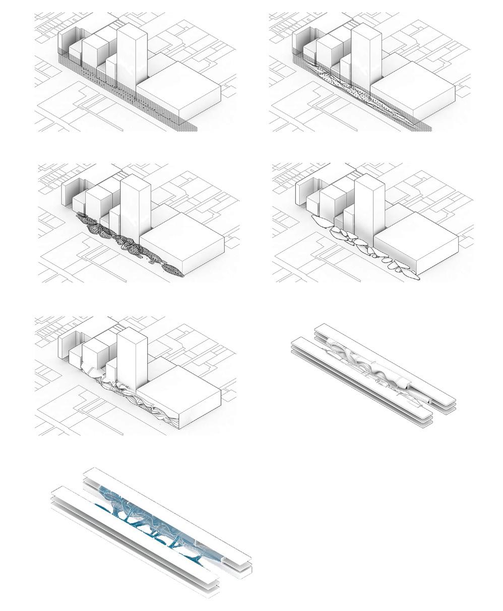
In design stage two, a specific street of the simulative city has been selected to receive some further teases and in the end a more integrated and dynamic building connecting to the existing buildings is created. The diagrams above show different steps of the form development process. Parametric techniques are applied to generate a series of connected spaces.

We believe this additional new building is like a bit of ‘ingredients’ grated on the original city, which picks up the imperfections of the current city without demolishing any existing buildings. Having these ‘ingredients’, the dish of the city becomes “tempting” and “yummy” again as a real Pudding City.

POBBLEBONK HOUSE
Eco-friendly Frog Habitat Design
Landscape Architecture Elective Work
2016, Semester 2
The University of Melbourne
Site: Melbourne, Victoria, Australia
Tutor: Mark Gillingham
Group Work (Partners: Chenyi Zhao, Wenxing Li)
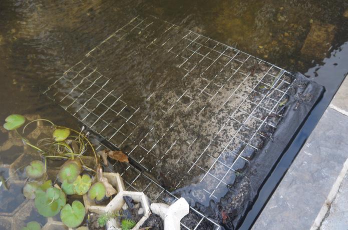
This is the final assignment of the course Landscape Materialities in the University of Melbourne. The assignment demands us to design and manufacture an additional installation in the Redmond Barry Courtyard Pond in the University of Melbourne to improve the micro-environment there so it becomes more eco-friendly and liveable for creatures in the pond.
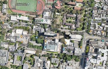
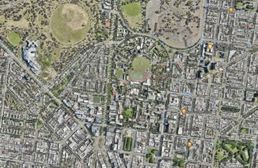
For university students passing here everyday, it just as normal as a small landscape pond that does not have any specialties, however, for the creatures living there, the pond is the whole world they are living in. So no matter what to be inserted here will actually change their living mode.
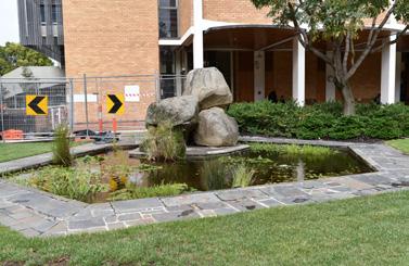
In this case, we aim to do more than just propose an installation design for a school pond, it is more like conceiving and optimising ‘a new world’ for them. As architects to be, our clients for this time are not human beings. I pretend that we are designing ‘houses’ for the ‘residents’ who are living in the pond.
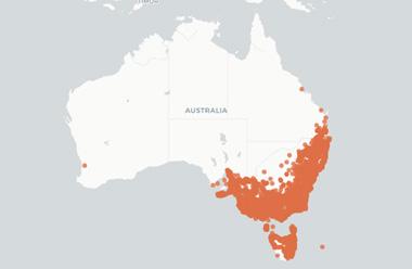
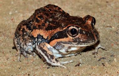
Therefore, before conduct our design, we need to understand who are the residents living there? According to the research, there is a special type of residents living in this pond. They are Eastern Banjo Frogs, which are also known as the Pobblebonks, mainly and only living in the South of Australia.
Pobblebonks are an important link in the food chain of ecosystems: they can help control insect pests from excessive multiplication; their tadpoles act as natural nutrient filters and can help control levels of algae in the pond; they can act as indicators of overall health of both aquatic and terrestrial environments.
Understanding the large number of their benefits for the environment, we decide to design a new ‘house’ for these small local residents - a Pobblebonks House.
POBBLEBONKS’ HABITAT
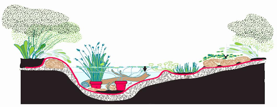
Pobblebonks mostly inhabit woodlands, wet and dry forests, heathland, farmland and grasslands. They are commonly seen after rain near dams, ditches and other bodies of still or slow-moving water. An ideal frog pond should contain deep water zone, shallow water bog zone and damp zone.
Deep Water Zone Damp Zone Shallow Water Bog Zone
Rocks and logs for shelter Summer low water level Winter deep water level
Pond Liner
INITIAL CONCEPT
Sands
Pobblebonks’ main habitats
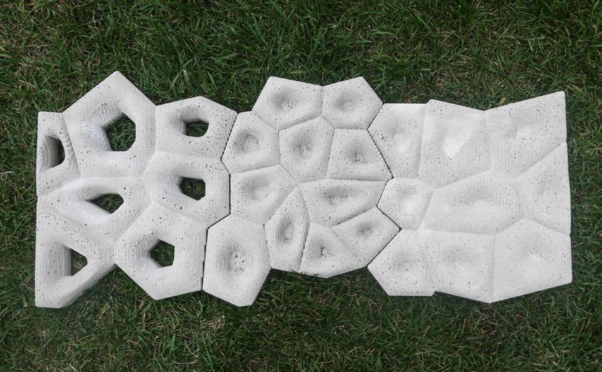
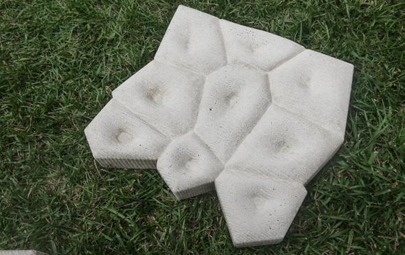
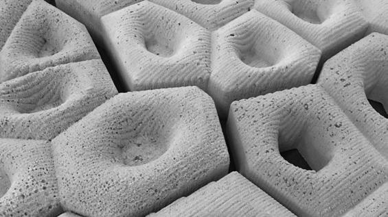
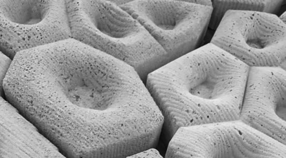
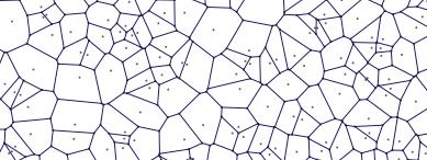
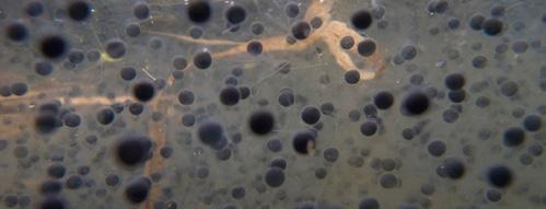
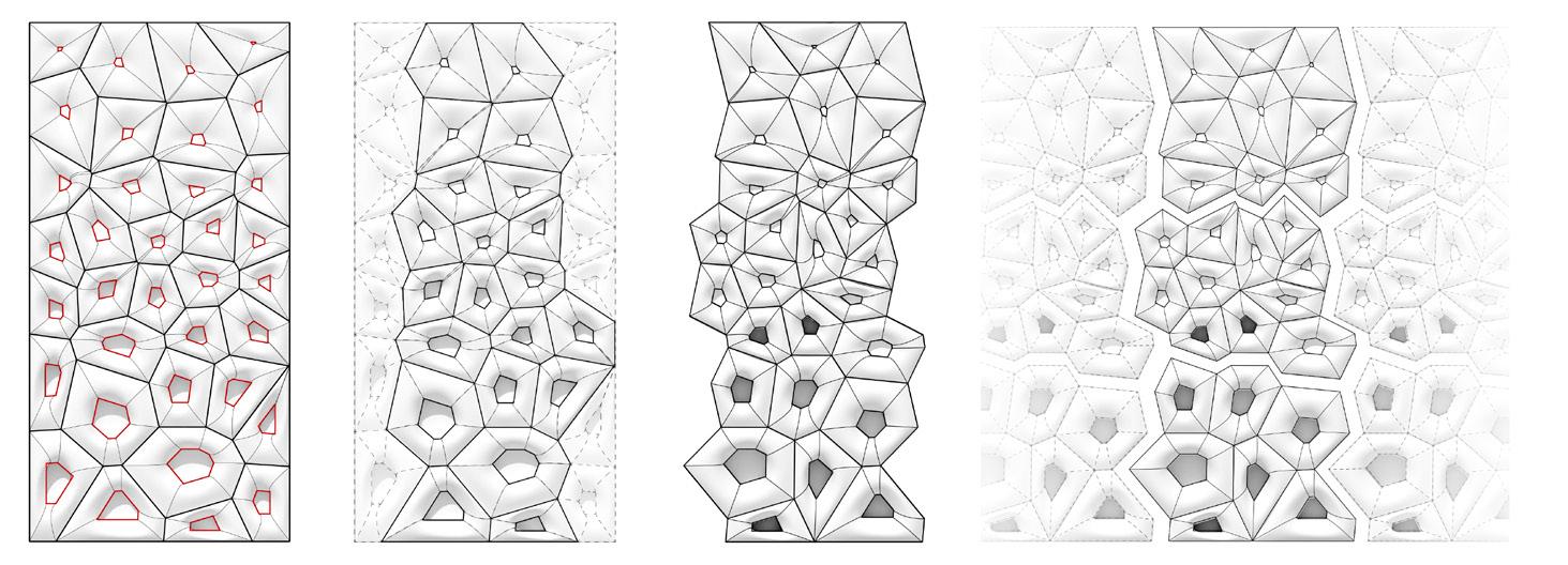
The design aims to produce an unique but friendly habitat for Pobblebonks. The idea of this project comes from the feature of spawns of Pobblebonks, When hundreds of thousands of Pobblebonk spawns heaping together, it looks like the classic pattern of Voronoi, which is a partitioning of a plane into regions based on distance to points in a specific subset of the plane.
3D PATTERN GENERATION
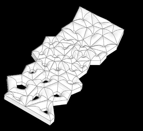
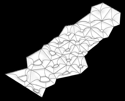
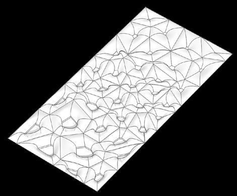
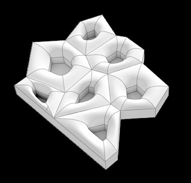


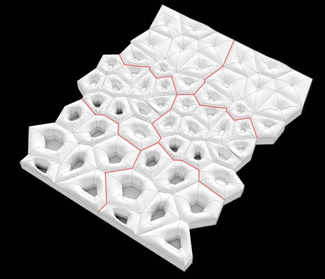
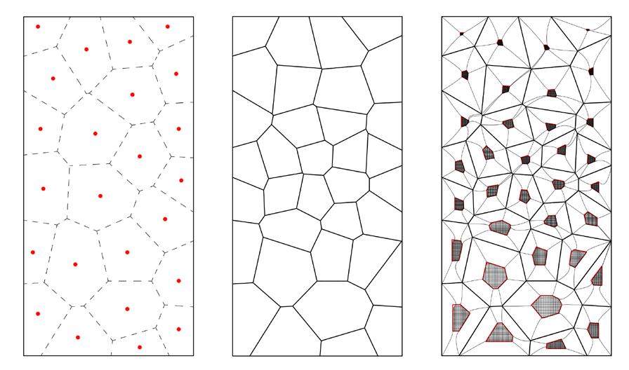
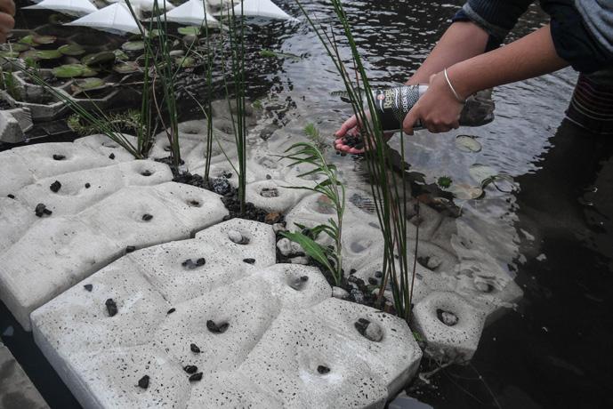
The idea is to create a consistent but varied patten for Pobblebonks in which includes deep water, shallow water and damp zones that satisfied the requirements that an ideal Pobblebonks habitat demands
Smallest and shallowest holes for rocks and logs, imitates damp environment
Shallower but denser holes for sands and small stones, imitates shallow water environment
Deep and large holes for algal growth, imitates deep water environment
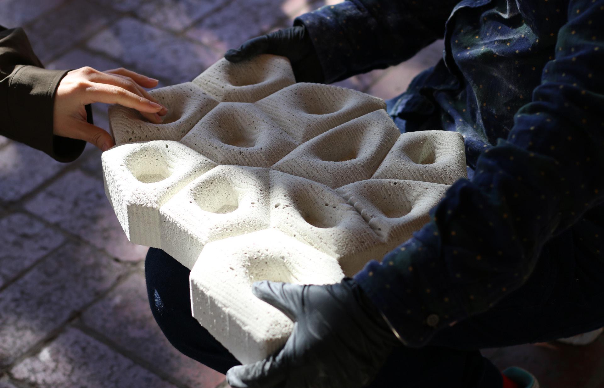
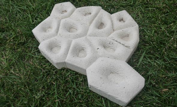
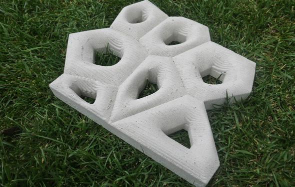
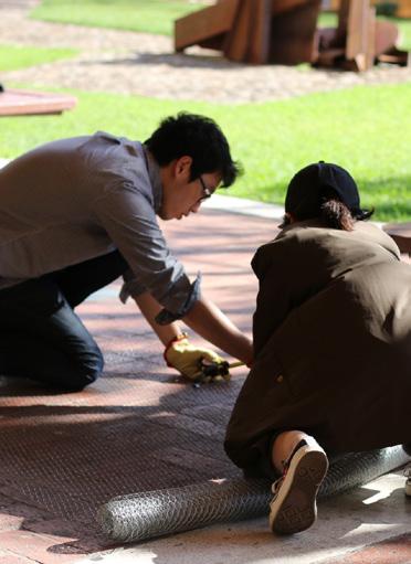
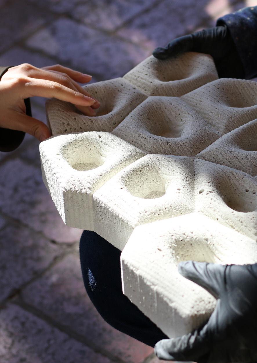
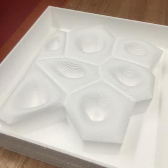
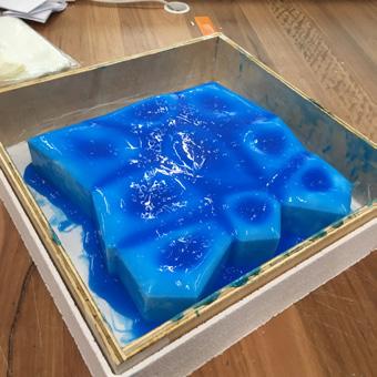
CONCRETE COMPONENT FABRICATIONS
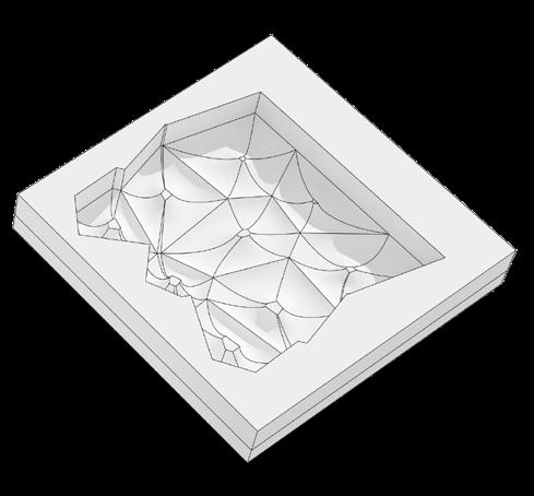

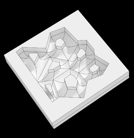
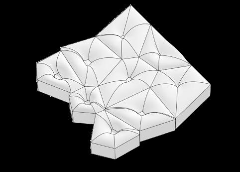
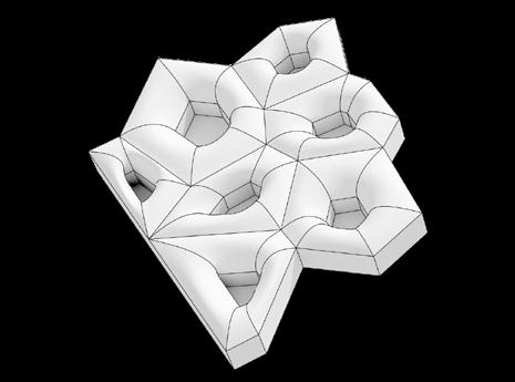
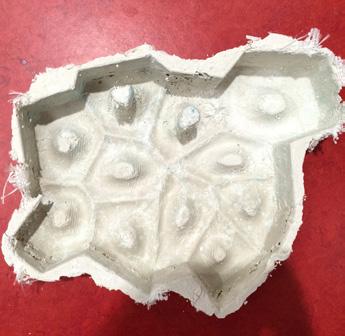
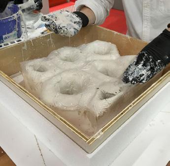
After several trys, the best fabrication solution has been work out:
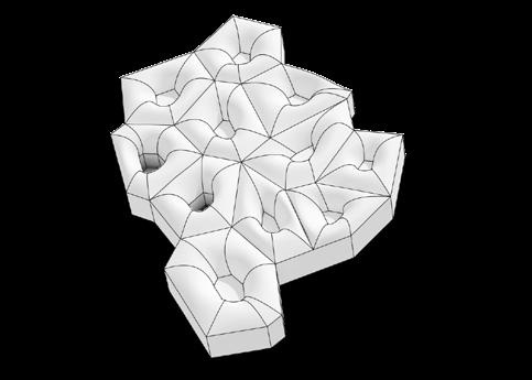
CONCRETE PATTERN COMPOSITION

