
Service Repair Manual
Models 428C BACKHOE LOADER
i02108297
Configuration: 428C Backhoe Loader Side Shift, Parallel Lift 2CR00001-16211 (MACHINE) POWERED BY 3054 Engine
NOTICE
Model: 428C BACKHOE LOADER 2CR
Start By:
Shutdown SIS
a. Remove the fuel injection lines. Refer to Disassembly and Assembly, "Fuel Injection Lines - Remove and Install".
Fuel Injection Nozzles - Remove
3054 Engine for Caterpillar Built Machines
Keep all parts clean from contaminants. Contaminants may cause rapid wear and shortened component life.
Refer to Special Publication, NENG2500, "Caterpillar Dealer Service Tool Catalog" for tools and supplies suitable to collect and contain fluids on Caterpillar products.

Media Number -SENR6241-13 Publication Date -01/08/2008 Date Updated -04/08/2008
Disassembly and Assembly
Previous Screen
NOTICE
Dispose of all fluids according to local regulations and mandates.
Product: BACKHOE LOADER
Care must be taken to ensure that fluids are contained during performance of inspection, maintenance, testing, adjusting and repair of the product. Be prepared to collect the fluid with suitable containers before opening any compartment or disassembling any component containing fluids.
SMCS - 1254-011
Removal Procedure
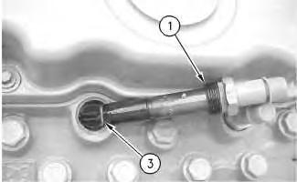
g00902564
Illustration 1
3. Remove seat washer (3).
Illustration 2
Copyright 1993 - 2019 Caterpillar Inc. All Rights Reserved. Private Network For SIS Licensees. Oct 15 17:30:18 UTC+0800
Tue
2019
g00902563
Note: If the original seat washer is not removed, the projection of the fuel injection nozzle will be incorrect when a new seat washer is installed.
1. Loosen threaded nut (1) on the fuel injection nozzle.
2. Remove fuel injection nozzle (2) from the cylinder block.


NOTICE
clean
head. 2. Install a new seat
into
Installation Procedure
all parts clean from contaminants. Contaminants may cause
Shutdown SIS Previous Screen Product: BACKHOE LOADER Model: 428C BACKHOE LOADER 2CR Configuration: 428C Backhoe Loader Side Shift, Parallel Lift 2CR00001-16211 (MACHINE) POWERED BY 3054 Engine Disassembly and Assembly 3054 Engine for Caterpillar Built Machines Media Number -SENR6241-13 Publication Date -01/08/2008 Date Updated -04/08/2008 i01760208
SMCS - 1254-012
and
life. Illustration 1 g00903765
threads on
and
1. Thoroughly the threaded nut (1) the cylinder washer (3) the recess in the cylinder head.
Fuel Injection Nozzles - Install
Keep rapid wear shortened component
4. Put fuel injection nozzle (2) into position in the cylinder head. Make sure that the detent ball in the fuel injection nozzle (2) is aligned correctly with ball Detent (X) in the cylinder head.


Illustration 2 g00903762
Note: If the original seat washer is reused, the projection of the fuel injection nozzle will be incorrect.
Illustration 4 g00902563
3. Put a 2.0 mm (0.08 inch) bead of 4C-5591 Anti-Seize Compound on the first two threads of threaded nut (1).
Illustration 3 g00903704
a. Install the fuel injection lines. Refer to Disassembly and Assembly, "Fuel Injection LinesRemove and Install".
Note: Do not rotate the fuel injection nozzle after installation. The seal which is made by the anti-seize compound may break. A broken seal may allow leakage past the seat of the fuel injection nozzle.
End By:
Copyright 1993 - 2019 Caterpillar Inc. All Rights Reserved. Private Network For SIS Licensees.
Tue Oct 15 17:31:15 UTC+0800 2019
5. Carefully tighten threaded nut (1) to a torque of 30 N·m (22 lb ft). Remove any excess AntiSeize Compound from fuel injection nozzle.
Product: BACKHOE LOADER
NOTICE
i01080672
3054 Engine for Caterpillar Built Machines
Contaminants may cause rapid wear and shortened component life.
Refer to Special Publication, NENG2500, "Caterpillar Tools and Shop Products Guide" for tools and supplies suitable to collect and contain fluids on Caterpillar products.
Disassembly and Assembly
Model: 428C BACKHOE LOADER 2CR
Configuration: 428C Backhoe Loader Side Shift, Parallel Lift 2CR00001-16211 (MACHINE) POWERED BY 3054 Engine
Dispose of all fluids according to local regulations and mandates.
Shutdown SIS
Keep all parts clean from contaminants.
Note: For a complete description of Type 1 and Type 2 Engines, refer to the Disassembly and Assembly, "Engine Design" topic.
Care must be taken to ensure that fluids are contained during performance of inspection, maintenance, testing, adjusting and repair of the product. Be prepared to collect the fluid with suitable containers before opening any compartment or disassembling any component containing fluids.
Media Number -SENR6241-13 Publication Date -01/08/2008 Date Updated -04/08/2008
Installation Procedure
SMCS - 1254-012
Previous Screen
NOTICE
Fuel Injection Nozzles - Install - Type 1 Engines and 9RM Engines
2019
2. Install the seat washer on the end of fuel injection nozzle (3) .

1. Install dust seal (5) and spacer (4) .
3. Install fuel injection nozzle (3) into the cylinder head.
g00545199
End By: Install the fuel injection lines. Refer to Disassembly and Assembly, "Fuel Injection Lines - Remove and Install".
Tue
g00545200
Illustration 2
Copyright 1993 - 2019 Caterpillar Inc. All Rights Reserved. Private Network For SIS Licensees. Oct 15 17:32:12 UTC+0800
4. Install clamp (2) and bolts (1). Tighten bolts (1) to a torque of 12 N·m (9 lb ft).
Illustration 1

Shutdown SIS Previous Screen Product: BACKHOE LOADER Model: 428C BACKHOE LOADER 2CR Configuration: 428C Backhoe Loader Side Shift, Parallel Lift 2CR00001-16211 (MACHINE) POWERED BY 3054 Engine Disassembly and Assembly 3054 Engine for Caterpillar Built Machines Media Number -SENR6241-13 Publication Date -01/08/2008 Date Updated -04/08/2008 i02105278 Fuel Injection Pump - Remove - Type 2 Engines and 7BJ Engines SMCS - 1251-011 Removal Procedure Table 1 Required Tools Tool Part Number Part Description Qty A 150-3992 Timing Pin (1) 1 150-3993 Timing Pin (2) 1 B 173-9774171-1085or Tamper Resistant Tool Gp 1 ( 1 ) Tool (A) is required in order to remove Bosch fuel injection pumps. ( 2 ) Tool (A) is required in order to remove Delphi (Lucas) and Stanadyne fuel injection pumps. Start By:
A.
Remove the water pump. Refer to Disassembly and Assembly, "Water Pump - Remove". B. Remove the fuel injection lines. Refer to Disassembly and Assembly, "Fuel Injection Lines - Remove and Install". NOTICE Keep all parts clean from contaminants. Contaminants may cause rapid wear and shortened component life.
2. Loosen locking screw (2) (if equipped) until locking spacer (1) moves freely. Move locking spacer (1) into position (B). Tighten locking screw (2) to a torque of 10 N·m (7 lb ft).
1. Ensure that the No. 1 cylinder is at the top center position on the compression stroke. Refer to the Testing and Adjusting, "Fuel System" topic for additional information.

Illustration 1
g00808245
Dispose of all fluids according to local regulations and mandates.
Refer to Special Publication, NENG2500, "Caterpillar Tools and Shop Products Guide" for tools and supplies suitable to collect and contain fluids on Caterpillar products.
Care must be taken to ensure that fluids are contained during performance of inspection, maintenance, testing, adjusting and repair of the product. Be prepared to collect the fluid with suitable containers before opening any compartment or disassembling any component containing fluids.
NOTICE
Note: Do not remove hub nut (4) from the shaft of the fuel injection pump. The hub of the fuel injection pump is installed in the correct position from the factory in order to ensure proper timing. If hub nut (4) is removed and the hub is removed, the hub will need to be accurately installed on the shaft of the fuel injection pump by the use of special equipment. Refer to your Caterpillar Dealer for more information.
Note: Do not release Torx screws (5) (if equipped). If the Torx screws are released and the timing plate is moved, the timing position that is set at the factory will be lost. If the Torx screws are released, the No. 1 cylinder must be set to the top center position on the compression stroke before the Torx screws are tightened.
Note: The location of Tool (A) for Bosch fuel injection pumps will be located toward the top of the fuel injection pump. The location of Tool (A) for Delphi (Lucas) and Stanadyne fuel injection pumps will be located toward the bottom of the fuel injection pump.
Illustration 2 g00808370
Typical example
3. Slowly rotate the crankshaft until hole (6) in the timing gear and hole (7) in the hub are in alignment with hole (8) in the fuel injection pump body.
4. Install Tool (A) through hole (6) in the timing gear and hole (7) in the hub. Push Tool (A) into position in hole (8) in the fuel injection pump body. If Tool (A) can be fully seated, the fuel injection pump timing is correct. No resistance should be felt when the timing pin is inserted into hole (8) of the fuel injection pump body.

6. Remove three flange nuts (10) and fuel injection pump (11) from the engine.

7. Remove O-ring seal (12) from fuel injection pump (11) .
Illustration 3 g00808376
5. Remove four bolts (3) that fasten the fuel injection pump gear to the fuel injection pump. Timing gear (9) should be free from the fuel injection pump shaft.

Illustration 4 g01059878
Typical example
Note: Some fuel injection pumps are installed with tamper proof bolts. Tool (B) may be necessary in order to remove the tamper proof bolts.
Typical example
Private Network For SIS Licensees.
Tue Oct 15 17:33:08 UTC+0800 2019
Copyright 1993 - 2019 Caterpillar Inc. All Rights Reserved.
Shutdown SIS Previous Screen Product: BACKHOE LOADER Model: 428C BACKHOE LOADER 2CR Configuration: 428C Backhoe Loader Side Shift, Parallel Lift 2CR00001-16211 (MACHINE) POWERED BY 3054 Engine Disassembly and Assembly 3054 Engine for Caterpillar Built Machines Media Number -SENR6241-13 Publication Date -01/08/2008 Date Updated -04/08/2008 i01083652 Fuel Injection Pump - Remove - Type 1 Engines and 9RM Engines SMCS - 1251-011 Removal Procedure Table 1 Required Tools Tool Part Number Part Description Qty A 173-9774 Bolt Remover (1) 1 B 9U-6198 Crankshaft Turning Tool 1 C 8S-2264 Puller Group 1 8S-4712 Bolt 2 ( 1 ) The bolt remover is required in order to remove the tamper proof bolts on the access cover for the fuel injection pump. Start By: A. Remove the water pump. Refer to Disassembly and Assembly, "Water Pump - Remove". B. Remove the fuel injection lines. Refer to Disassembly and Assembly, "Fuel Injection Lines - Remove and Install". Note: For a complete description of Type 1 and Type 2 engines, refer to the Disassembly and Assembly, "Engine Design" topic. NOTICE Keep all parts clean from contaminants.
NOTICE
1. Remove four bolts (1) .
2. Remove cover (2) .
Dispose of all fluids according to local regulations and mandates.
g00545256
Illustration 1
Note: Some engines may have four tamper proof bolts (1). Use Tool (A) in order to remove the tamper proof bolts bolts.

Refer to Special Publication, NENG2500, "Caterpillar Tools and Shop Products Guide" for tools and supplies suitable to collect and contain fluids on Caterpillar products.
Care must be taken to ensure that fluids are contained during performance of inspection, maintenance, testing, adjusting and repair of the product. Be prepared to collect the fluid with suitable containers before opening any compartment or disassembling any component containing fluids.
Contaminants may cause rapid wear and shortened component life.
4 g00571373
Illustration
Illustration
4. Use Tool (B) to rotate the crankshaft until keyway (X) is at 30 degrees from the vertical centerline.


and
g00571370
Illustration 3
2 g00545258
3. Remove nut (3) the lockwasher.
6. Disengage the gear from the fuel injection pump.

8. Remove three nuts (6) that hold fuel injection pump (5) in position.
5. Install Tool (C)
7. Disconnect hose (7) from the fuel injection pump.
9. Remove fuel injection pump (5) and the gasket.
Note: Ensure that you do not lose the key when the fuel injection pump is removed. Also notice the position of marks (4) in order to ensure proper alignment of fuel injection pump (5) during installation.
.
Illustration 5 g00545262
Tue Oct 15 17:34:05 UTC+0800 2019
Copyright 1993 - 2019 Caterpillar Inc. All Rights Reserved. Private Network For SIS Licensees.
Shutdown SIS Previous Screen Product: BACKHOE LOADER Model: 428C BACKHOE LOADER 2CR Configuration: 428C Backhoe Loader Side Shift, Parallel Lift 2CR00001-16211 (MACHINE) POWERED BY 3054 Engine Disassembly and Assembly 3054 Engine for Caterpillar Built Machines Media Number -SENR6241-13 Publication Date -01/08/2008 Date Updated -04/08/2008 i02046409 Fuel Injection Pump - Install - Type 2 Engines and 7BJ Engines SMCS - 1251-012 Installation Procedure Table 1 Required Tools Tool Part Number Part Description Qty A 150-3992 Timing Pin (1) 1 150-3993 Timing Pin (2) 1 B 173-9774171-1085or Tamper Resistant Tool Gp 1 ( 1 ) Tooling (A) is required in order to install Bosch fuel injection pumps. ( 2 ) Tooling (A) is required in order to install Dephi (Lucas) and Stanadyne fuel injection pumps. NOTICE Keep all parts clean from contaminants. Contaminants may cause rapid wear and shortened component life.
Typical example
Typical example
1. Check the condition of O-ring seal (13) on fuel injection pump (12). If the seal is worn or damaged, replace the seal.
Illustration 1
NOTICE
2. Lightly lubricate O-ring seal (13) with clean engine oil. Install O-ring seal (13) on fuel injection pump (12) .
The No. 1 cylinder must be at the top center position on the compression stroke before the fuel injection pump is installed. If the crankshaft needs to be rotated, the fuel injection pump must be mounted temporarily or the loose gear could cause damage to the front housing.
Illustration 2
g00808376
g01059878
Thank you very much for your reading. Please Click Here. Then Get COMPLETE IfNOTE:MANUAL.NOWAITINGthereisnoresponse to click on the link above, please download the PDF document first and then clickonit.

4. Position gear (9) on the shaft of the fuel injection pump.
Illustration 3 g00808370
Note: Some fuel injection pumps are installed with tamper proof bolts. Tooling (B) may be necessary in order to install the tamper proof bolts.
Typical example
3. Put fuel injection pump (12) in position on the engine. Ensure that the timing gear is aligned with the hub of fuel injection pump (12). Install three flange nuts (11) and tighten the flange nuts to a torque of 28 N·m (21 lb ft).
5. Put the timing gear plate in position and install four bolts (3). Tighten the four bolts finger tight.
Note: The fuel injection pump gear will only fit in one position. Install the gear with the letters "C" and "M" facing away from the engine.
7. Install Tooling (A) through hole (6) in the timing gear and hole (7) in the hub. Push Tooling (A) into position in hole (8) in the fuel injection pump body. If Tooling (A) can be fully seated, the fuel injection pump timing is correct. No resistance should be felt when the timing pin is inserted into hole (8) of the fuel injection pump body.
Note: The location of Tooling (A) for Bosch fuel injection pumps will be located toward the top of the fuel injection pump. The location of Tooling (A) for Dephi (Lucas) and Stanadyne fuel injection pumps will be located toward the bottom of the fuel injection pump.
NOTICE
Illustration 4 g00808245
9. Remove Tooling (A) from the fuel injection pump gear.
8. When the timing plate is installed, rotate gear (9) by hand in a counterclockwise direction in order to remove the backlash between gear (9) and the idler gear. Do not rotate the crankshaft or the fuel injection pump shaft. Tighten bolts (3) to a torque of 28 N·m (21 lb ft).
The fuel injection pump may be supplied with the fuel injection pump shaft in the locked position. The drive shaft of the fuel injection pump must not be rotated without the spacer in position under the locking screw. Damage to the drive shaft of the fuel injection pump will result.
6. Loosen locking screw (2) (if equipped) until locking spacer (1) moves freely. Move locking spacer (1) into position (A). Tighten locking screw (2) to a torque of 10 N·m (7 lb ft).
Typical example
End By:
Copyright 1993 - 2019 Caterpillar Inc. All Rights Reserved. Private Network For SIS Licensees.
a. Install the fuel injection lines. Refer to Disassembly and Assembly, "Fuel Injection LinesRemove and Install".
b. Install the water pump. Refer to Disassembly and Assembly, "Water Pump - Install".
Tue Oct 15 17:35:02 UTC+0800 2019
Shutdown SIS Previous Screen Product: BACKHOE LOADER Model: 428C BACKHOE LOADER 2CR Configuration: 428C Backhoe Loader Side Shift, Parallel Lift 2CR00001-16211 (MACHINE) POWERED BY 3054 Engine Disassembly and Assembly 3054 Engine for Caterpillar Built Machines Media Number -SENR6241-13 Publication Date -01/08/2008 Date Updated -04/08/2008 i01083913
Inspect the condition of the gasket for the fuel injection pump. Replace the gasket, if necessary.
Fuel Injection Pump - Install - Type 1 Engines and 9RM Engines Type
1.
2 Engines, refer to the Disassembly and Assembly, "Engine Design" topic. NOTICE Keep all parts clean from contaminants. Contaminants may cause rapid wear and shortened component life.
SMCS - 1251-012 Installation Procedure Table 1 Required Tools Tool Part Number Part Description Qty A 173-9774 Bolt Remover (1) 1 ( 1 ) The bolt remover is required in order to install the tamper proof bolts on the access cover for the fuel injection pump. Note: For a complete description of Type 1 and
5. Connect hose (7) to fuel injection pump (5) .
Note: Align marks (4) that are on fuel injection pump (5) and the timing gear cover.
Illustration 1 g00545262
6. Engage the gear with the fuel injection pump.
3. Install the key.
Illustration 2 g00545258
7. Install the lockwasher and nut (3) .
2. Install the gasket and fuel injection pump (5) .
4. Install three nuts (6) that hold fuel injection pump (5) in position.