INTRODUCTION
Engine . . . . . . . . . . . . . . . . . . . . . . . . . . . . . . . . . . . . . . . . . . . . . . . . . . . . . . . . . . . . . . . . . . . . . . . . . . . . . . . . . . . . . . .
[10.001] Engine and crankcase . . . . . . . . . . . . . . . . . . . . . . . . . . . . . . . . . . . . . . . . . . . . . . . . . . . . . . . . . . . . . 10.1
[10.202] Air cleaners and lines . . . . . . . . . . . . . . . . . . . . . . . . . . . . . . . . . . . . . . . . . . . . . . . . . . . . . . . . . . . . . . 10.2
[10.206] Fuel filters . . . . . . . . . . . . . . . . . . . . . . . . . . . . . . . . . . . . . . . . . . . . . . . . . . . . . . . . . . . . . . . . . . . . . . . . . . 10.3 [10.304]
. . . . . . . . . . . . . . . . . . . . . . . . . . . . . . . . . . . . . . . . . . . . . . . . . . . . . . . . . . 10.4 [10.400]
Contents
Engine
[10.501] Exhaust Gas Recirculation (EGR) exhaust treatment .
Clutch . . . . . . . . . . . . . . . . . . . . . . . . . . . . . . . . . . . . . . . . . . .
.
. .
. . . . . . . . . . . . . . . . . . . . . . . . . . . . . . . . . . Clutch mechanical release control [18.1 10] Clutch and components . . . . . . . . . . . . . . . . . . . . . . . . . . . . . . . . . . . . . . . . . . . . . . . . . . . . . . . . . . . . 18.2 [18.1 12] Slip clutch flywheel damper . . . . . . . . . . . . . . . . . . . . . . . . . . . . . . . . . . . . . . . . . . . . . . . . . . . . . 18.3 T ransmission . . . . . . . . . . . . . . . . . . . . . . . . . . . . . . . . . . . . . . . . . . . . . . . . . . . . . . . . . . . . . . . . . . . . . . . . . . . . . . 14] Mechanical transmission Mechanical transmission external controls [21.140] Mechanical transmission internal components . . . . . . . . . . . . . . . . . . . . . . . . . . . . . . . . . . . . . 21.3 Front axle system . . . . . . . . . . . . . . . . . . . . . . . . . . . . . . . . . . . . . . . . . . . . . . . . . . . . . . . . . . . . . . . . . . . . . . . Powered front axle Front bevel gear set and dif ferential Final drives Rear axle system . . . . . . . . . . . . . . . . . . . . . . . . . . . . . . . . . . . . . . . . . . . . . . . . . . . . . . . . . . . . . . . . . . . . . . . . [27.106] Rear bevel gear set and dif ferential . . . . . . . . . . . . . . . . . . . . . . . . . . . . . . . . . . . . . . . . . . . . . . . . 27.1 [27.120] Planetary and final drives . . . . . . . . . . . . . . . . . . . . . . . . . . . . . . . . . . . . . . . . . . . . . . . . . . . . . . . . . . 27.2 Hydrostatic drive . . . . . . . . . . . . . . . . . . . . . . . . . . . . . . . . . . . . . . . . . . . . . . . . . . . . . . . . . . . . . . . . . . . . . . . . . T ransmission and steering hydrostatic control Hydrostatic transmission 47941899 16/03/2016
Engine lubrication system
cooling system . . . . . . . . . . . . . . . . . . . . . . . . . . . . . . . . . . . . . . . . . . . . . . . . . . . . . . . . . . . . . 10.5
. . . . . . . . . . . . . . . . . . . . . . . . . . . . . 10.6
.
.
. . . . .
Pump and motor components Power T f (PT . . . . . . . . . . . . . . . . . . . . . . . . . . . . . . . . . . . . . . . . . . . . . . . . . . . . . . . . . . . . . . . . . Rear mechanical control Rear control 10] rear Power T f (PT [31.120] Central Power T f (PT . . . . . . . . . . . . . . . . . . . . . . . . . . . . . . . . . . . . . . . . . . . . . . . . . . . . . 31.4 Brakes and controls . . . . . . . . . . . . . . . . . . . . . . . . . . . . . . . . . . . . . . . . . . . . . . . . . . . . . . . . . . . . . . . . . . . . 10] Parking brake parking lock Mechanical service brakes Hydraulic systems Hydraulic systems Fixed displacement pump 14] hitch control valve 16] hitch cylinder Remote control valves Reservoir , cooler , and filters Safety and main relief valves Hydraulic hand control Hitches, drawbars, and implement couplings . . . . . . . . . . . . . . . . . . . . . . . . . . . . . . . . . . [37.108] Rear three-point hitch external controls . . . . . . . . . . . . . . . . . . . . . . . . . . . . . . . . . . . . . . . . . . . . 37.1 [37.1 10] Rear hitch . . . . . . . . . . . . . . . . . . . . . . . . . . . . . . . . . . . . . . . . . . . . . . . . . . . . . . . . . . . . . . 37.2 Rear hitch linkage Steering . . . . . . . . . . . . . . . . . . . . . . . . . . . . . . . . . . . . . . . . . . . . . . . . . . . . . . . . . . . . . . . . . . . . . . . . . . . . . . . . . . . . . Steering control T rods [41.200] Hydraulic control components . . . . . . . . . . . . . . . . . . . . . . . . . . . . . . . . . . . . . . . . . . . . . . . . . . . . . . 41.3 Cylinders Wheels 47941899 16/03/2016
Front wheels Rear wheels Cab climate control [50.100] Heating . . . . . . . . . . . . . . . . . . . . . . . . . . . . . . . . . . . . . . . . . . . . . . . . . . . . . . . . . . . . . . . . . . . . . . . . . . . . . 50.1 [50.104] V entilation . . . . . . . . . . . . . . . . . . . . . . . . . . . . . . . . . . . . . . . . . . . . . . . . . . . . . . . . . . . . . . . . . . . . . . . . . . 50.2 [50.200] Air conditioning . . . . . . . . . . . . . . . . . . . . . . . . . . . . . . . . . . . . . . . . . . . . . . . . . . . . . . . . . . . . . . . . . . . . . 50.3 Electrical systems . . . . . . . . . . . . . . . . . . . . . . . . . . . . . . . . . . . . . . . . . . . . . . . . . . . . . . . . . . . . . . . . . . . . . . . Electrical system Fuel tank system Parking brake electrical system Rear Power T f (PT control system Harnesses and connectors Engine starting system Cold start aid Battery External lighting External lighting switches and relays W arning and instruments 1 Cab transmission controls Wiper and washer system Cab engine controls Ground speed control Electronic modules Exhaust Gas Recirculation (EGR) electrical system F AUL T CODES Platform, cab, bodywork, and decals . . . . . . . . . . . . . . . . . . . . . . . . . . . . . . . . . . . . . . . . . . . . . [90.100] Engine hood and panels . . . . . . . . . . . . . . . . . . . . . . . . . . . . . . . . . . . . . . . . . . . . . . . . . . . . . . . . . . . 90.1 [90.1 14] Operator protections . . . . . . . . . . . . . . . . . . . . . . . . . . . . . . . . . . . . . . . . . . . . . . . . . . . . . . . . . . . . . . . 90.2 47941899 16/03/2016
operator seat
Cab
Cab interior
Cab doors and hatches
Cab glazing
16] Fenders and guards
47941899 16/03/2016

47941899 16/03/2016 1
INTRODUCTION
This repair manual provides the technical information needed properly service the NEW HOLLAND models Boomer and Use this manual conjunction with the manual for complete and maintenance information
NEW HOLLAND left and right are determined standing behind the looking the direction
NOTICE: Emissions sensors the exhaust system and the vehicle may damaged vibrations from use impact wrenches hammers during service A void using these tools when servicing components close the sensors. Remove the sensors with care use these tools cannot avoided.
INTRODUCTION
Boomer™ Boomer™
Foreword
47941899 16/03/2016 3
Safety rules
Personal safety
This the safety alert used alert you potential personal injury Obey all safety messages that follow this symbol avoid possible death injury .

Throughout this manual you will find the signal words DANGER, W ARNING, and CAUTION followed special These precautions are intended for the personal safety you and those working with Read and understand all the safety messages this manual before you operate service the machine. DANGER indicates a hazardous situation not will result death serious injury W ARNING indicates a hazardous situation not could result death serious injury CAUTION indicates a hazardous situation that, not avoided, could result minor moderate injury .
F AILURE T O FOLLOW
MESSAGES COULD RESUL T DEA SERIOUS INJUR Y
Machine safety
DANGER, W ARNING, AND CAUTION
.
NOTICE: Notice indicates a situation not could result machine property
Throughout this manual you will find the signal word Notice followed special instructions prevent machine property The word Notice used address practices not related personal safety
Information
NOTE: Note indicates additional information that clarifies other information this
Throughout this manual you will find the word Note followed additional information about a other information the The word Note not intended address personal safety property
INTRODUCTION
Boomer™ Boomer™
47941899 16/03/2016 4
SER VICE MANUAL Engine Boomer™ Boomer™ TIER (FINAL), Cab Boomer™ TIER (FINAL), ROPS 47941899 16/03/2016

Engine Engine and crankcase
47941899 16/03/2016 10.1 [10.001] / 3
Engine and crankcase - Exploded view – Air cleaner NHIL14CT00166F A 1 (1) x Hex bolt (5) Air intake adapter hose (2) Air intake pipe (6) Safety filter (3) ° Air intake hose (7) Primary element (4) Hose clamps (8) 6 Air cleaner housing
Chock all four wheels that the tractor cannot Disconnect the negative ( battery cable (1)
93102237 1
Disconnect the headlight wire harness. Remove the (See Hood - Remove (90.100) Hood Remove
Disconnect the main and engine wire harnesses.
T urn f fuel supply the filter (1) , and then disconnect fuel 93102239 2
Position a drain pan collect drain oil and unfasten clamps (1)

Disassemble the suction tube assembly (2) 93102240 3

Engine Engine and crankcase
Boomer™ Boomer™
Engine - Remove
TIER ROPS
47941899 16/03/2016 10.1 [10.001] / 4
Unfasten the knobs (2) both rear cover halves (1) and 93102241 4
10. Remove mat (1) .
1 Unscrew the nuts and bolts and remove cover (2) 93102242 5
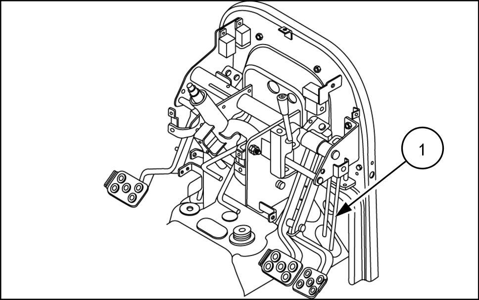
Unfasten bolts (2) and remove pedals (1) 93102243 6


Unfasten seven and one M24 bolts (3)
Remove the right hand step (1) and left hand step (2) 93102244 7
Engine Engine and crankcase
47941899 16/03/2016 10.1 [10.001] / 5
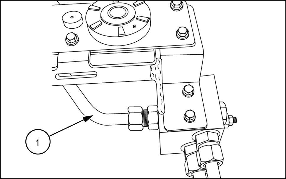
15. Disconnect the front high pressure tube (1) . 93102245 8
16. Disconnect the steering hoses (1) and tubes (2) . 93102246 9


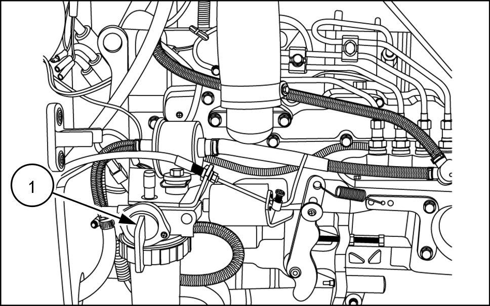
Disconnect the brake rod (1) ; Hydrostatic gear 93102247
Disconnect the brake rod (1) the right hand side and clutch rod the left - hand side; gear transmission only .
Engine Engine and crankcase
47941899 16/03/2016 10.1 [10.001] / 6
93102248 1 1
19. Unfasten bolts (2) securing the frame (1) the
Remove the frame (2) 93102251
21. Use a hoist carefully remove the firewall (1) . 93102252
Disconnect and remove the oil cooler (1) and related shown figure 93102253


Attach a chain sling (2) the two hoist eyes the
NOTE: One located the left hand side above the haust manifold, the other the right hand side the rear the injector
Attach a suitable hoist the chain sling and secure the tractor for separation.
25. Roll a floor jack (1) under the tractor from the rear the tractor , and place under the clutch Raise the jack enough support the drive

Engine Engine and crankcase
47941899 16/03/2016 10.1 [10.001] / 7
93105782
26. Unfasten eight M12 bolts (1) holding the engine (3) and transmission (2) , while checking front wheel drive shaft for separation from the
NOTE: The hoist and / the floor jack may need raised lowered allow the separation the engine from the clutch

Use the floor jack for support and carefully roll the drive train away from the 93102254 93105783

Engine Engine and crankcase
47941899 16/03/2016 10.1 [10.001] / 8
Engine - Remove
TIER Cab
Chock all four wheels that the tractor cannot Disconnect the negative ( battery cable (1) . 93102237 1 Disconnect the headlight wire harness. 93102238 2
Remove the hood. (See Hood Remove (90.100) Hood - Remove
Disassemble pin (3) hood strut and wire harness nector Remove the hinge cover and M8x16 bolt (2) . Carefully remove the hood (1) . Disconnect the main and engine wire harnesses. T urn f fuel supply the filter (1) , and then disconnect fuel 93102239 3

Engine Engine and crankcase
47941899 16/03/2016 10.1 [10.001] / 9
10. Position a drain pan collect drain oil and unfasten clamps (1)

1 Disassemble the suction tube assembly (2)
NHIL14CT00485F A 4
Remove the four knobs (2) both rear cover halves (1) and

Remove the four screws (3) , and remove the lower panel (4) .
Remove mat (1)
NHIL16CT00122AA 5
Unscrew the nuts and bolts and remove cover (2) 93102242 6
Unfasten bolts (2) and remove pedals (1)
Engine Engine and crankcase
47941899 16/03/2016 10.1 [10.001] /
93102243 7
17. Unfasten seven and one M24 bolts (3) .
Remove the right hand step (1) and left hand step (2) 93102244 8
19. Disconnect the front high pressure tube (1) . 93102245 9
Disconnect the steering hoses (1) and tubes (2) 93102246
Disconnect the brake rod (1) ; Hydrostatic gear 93102247
Engine Engine and crankcase
47941899 16/03/2016 10.1 [10.001] / 1 1
1 1
22. Disconnect the brake rod (1) the right hand side and clutch rod the left hand side; gear transmission only 93102248
23. Unfasten bolts (2) securing the frame (1) the Remove the frame (2) 93102251
Use a hoist carefully remove the firewall (1) 93102252
Disconnect and remove the oil cooler (1) and related shown figure 93102253
Engine Engine and crankcase
47941899 16/03/2016 10.1 [10.001] /
27. Attach a chain sling (2) the two hoist eyes the
NOTE: One located the left - hand side above the exhaust manifold, the other the right hand side the rear the injector
Attach a suitable hoist the chain sling and secure the tractor for
29. Roll a floor jack (1) under the tractor from the rear the tractor , and place under the clutch Raise the jack enough support the drive

30. Unfasten eight M12 bolts (1) holding the engine (3) and transmission (2) , while checking front wheel drive shaft for separation from the
NOTE: The hoist and / the floor jack may need raised lowered allow the separation the engine from the clutch
Use the floor jack for support and carefully roll the drive train away from the
Engine Engine and crankcase
93105782
47941899 16/03/2016 10.1 [10.001] /
93102254 93105783
Engine - Install
Roll a floor jack (1) under the tractor from the rear the tractor , and place under the clutch Raise the jack enough support the drive
Attach a chain sling (2) the two hoist eyes the gine, and position the engine into place the tractor .
NOTE: The hoist and / the floor jack may need raised lowered allow the engine and clutch housing mate. 93105782 1
Install eight M12 bolts (1) secure the engine (3) the transmission (2) 93102254 2 93105783 3
Install and connect the oil cooler (1) and related
Engine Engine and crankcase
Boomer™ Boomer™
TIER ROPS
93102253
47941899 16/03/2016 10.1 [10.001] /
4
Use a hoist carefully install the firewall (1) . 93102252 5
Position the frame (2) into place.
Install the bolts (2) secure the frame (1) the 93102251 6
Connect the brake rod (1) the right hand and clutch rod the left - hand
NOTE: Gear transmission only 93102248 7
Connect the brake rod (1) 93102247 8
Engine Engine and crankcase
47941899 16/03/2016 10.1 [10.001] /

Thank you very much for your reading. Please Click Here. Then Get COMPLETE MANUAL.NOWAITING NOTE: If there is no response to click on the link above, please download the PDF document first and then clickonit.
10.
Connect the steering hoses (1) and tubes (2) . 93102246 9
1 Connect the front high pressure tube (1) . 93102245
Position the right hand step (1) and left hand step (2) into
Install seven bolts and one M24 bolt (3) secure the steps. 93102244 1 1
Install the pedals (1) and secure with bolts (2) 93102243
Engine Engine and crankcase
47941899 16/03/2016 10.1 [10.001] /
15. Install the cover (2) and secure with the nuts and
Install the mat (1) 93102242
17. Install the rear cover halves (1) and secure with the knobs (2) 93102241
Assemble the suction tube assembly (2) and secure with the clamps (1) 93102240
Connect the fuel and then turn the fuel supply the filter (1)
Connect the main and engine wire 93102239
Install the (See Hood - Install HoodInstall (90.100)
Connect the headlight wire
Engine Engine and crankcase
47941899 16/03/2016 10.1 [10.001] /
