20 25 PEI-HSUAN HSU
Architectural Portfolio

Architectural Portfolio
hsupei1229@gmail.com
https://www.linkedin.com/in/hsuph
Regarding my background in architecture, I had 3.5 years of Architectural Designer and 8 months of on-site BIM/Construction Engineer experience prior to my master’s degree. I developed the design layout and strategies throughout the 3D modelling for the concept design, diagram and building permits, familiarity with Adobe Creative Suite, AutoCAD and Revit. I also modelled the custom Revit families and templates for the project as needed. To enhance my industry experience, I decided to work on the construction site as the BIM/Construction Engineer for a residential project. I conducted construction drawings and led the weekly clash review meeting with the architect and client. Additionally, I coordinated with BIM consultants to run the clashes detected and assisted the company to transform to the BIM working system by building up the working progress, family library, and templates. I am willing and confident in self-learning for software skills and seeking to improve the efficiency throughout the digital project delivery.
During my placement with the Façade Engineering Team at Mott MacDonald, I conducted the façade detail drawings and coordinated with multidisciplinary teams for the façade specifications and risk assessment for the RIBA stage 3 package of a the Stansted Airport Expansion. Additionally, I was involved in site inspection and a roof leak investigation and conducted the report, which further solidified my technical and analytical skills. I understood the importance of keeping my knowledge up-to-date, especially after the Building Safety Act and Gateways process, and I am committed to continuously learning and training to deliver tasks and make a difference in safety, sustainability and innovation. To further enhance knowledge in sustainable design, I took the Passive House training course and successfully certificated as a Passive Designer. My dissertation, Evaluation of façade refurbishment with respect to carbon and cost impact, further solidified my understanding not only in sustainability but also in the life-cycle carbon impact of façade systems.
Experience
Placement Student with Façade Engineering Team
Mott MacDonald, United Kingdom
BIM Engineer / Construction Engineer
TOP Construction Co, Ltd., Taiwan
Architectural Designer
XRANGE Architects, Taiwan
Education
Master of Science in Modern Building Design
University of Bath, United Kingdom
Bachelor of Architecture in Architecture
Feng Chia University, Taiwan
July 2024 - Dec 2024
Jan 2023 - Aug 2023
Jan 2019 - May 2022
Sept 2023 - Jan 2025
Sept 2013 - Jun 2018

London, United Kingdom
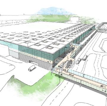
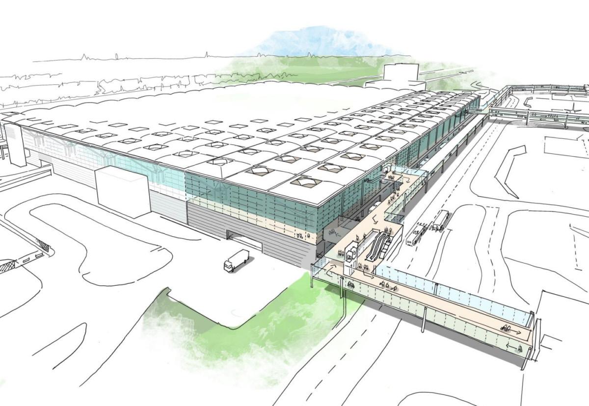
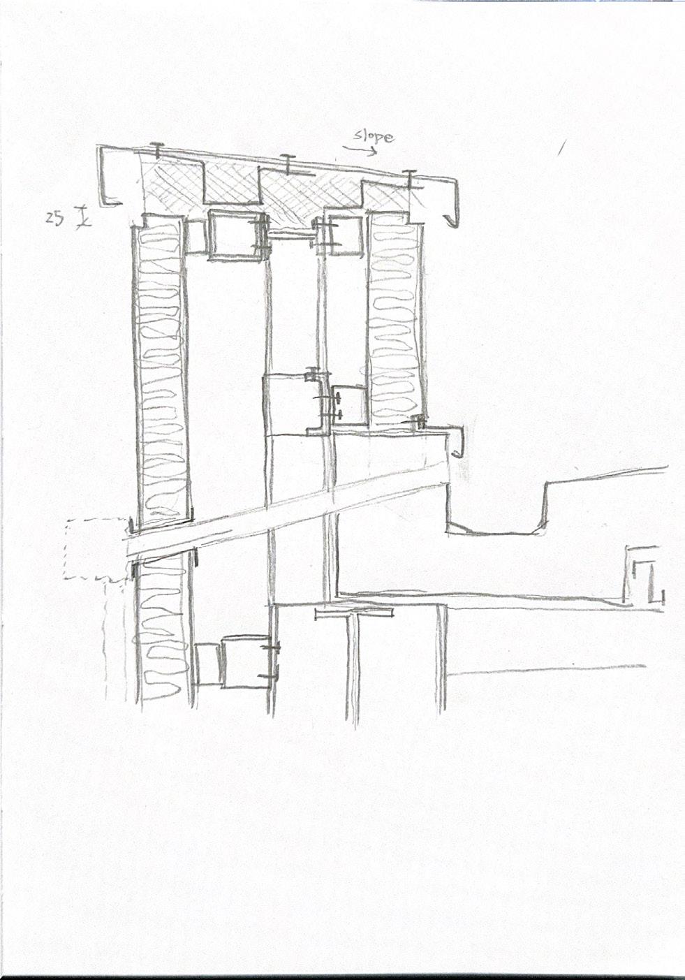
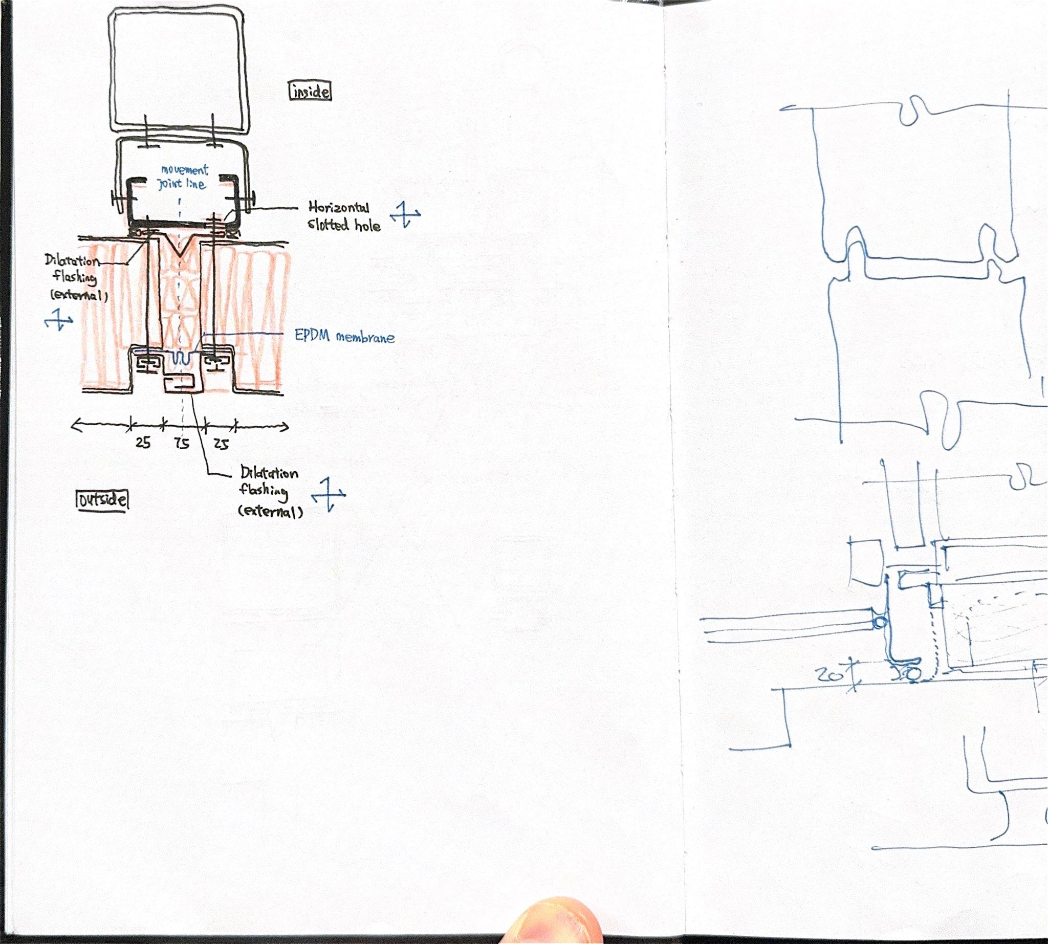
The airport expansion, as Façade Engineering Team, is focused on the build-up of the design details and specification for the new façade while remain the original design language, including the curtain wall, glass specification and roof.
I was involved in the façade detail drawings and specifications with coordination with the Structure Team, Fire Engineering Team, and Building Physics Team internally, aiming to provide a RIBA stage 3 deliverable package to the client and continuously provide consultation advices for the project progress.
TYPE
CLIENT
DESIGN TEAM
ROLE
CONTRIBUTION
CREDIT
July 2024 - Dec. 2024
Aviation Project
Manchester Airports Group (MAG)
Mott MacDonald and Pascall+Watson
Placement Student at Façade Engineering
· Produced façade detail drawings for the RIBA stage 3 deliverable
· Assisted with the façade specification and glass risk assessment
· Involved in site inspection and produced the inspection report
· Investigated the roof leak
· Assisted with consultation on façade system for the new-built project in Saudi Arabia
Mott MacDonald (Confidential)
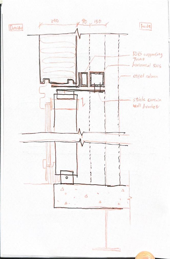
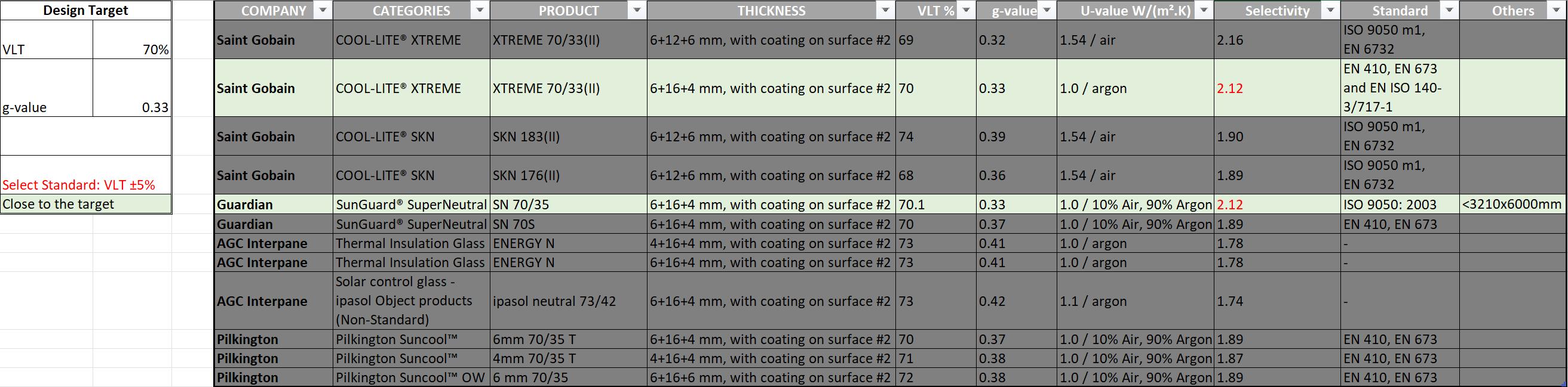
The expansion is focused on the build-up of the design details and specification for the new façade while remain the original design language, including the curtain wall, glass specification and roof. Therefore, it is important to find out the glass in the current market to match the original not only the Visible Light Transmittance (VLT) but also compliance with the current Building Regulations.
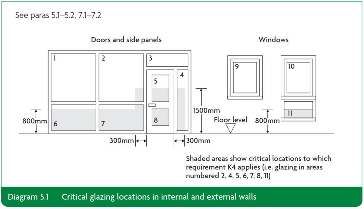
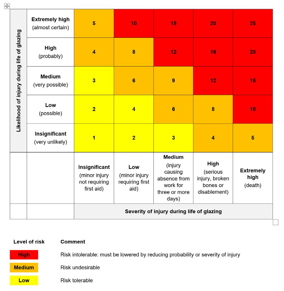
On the other hand, the purpose of the risk assessment is to consider each of the proposed glazing configurations and evaluate the level of risk associated with those configurations in their given location and under the circumstances in which the building will be used. CIRIA’s Guidance on Glazing at Height document was published in 2005 to provide authoritative guidance on the use of glazing at height. Approved Document K also outlines determines the critical locations within a building where glass is required to ‘break safely’ (if it breaks at all) under impact. These risk assessments consider the risks associated with the glass selection for the Extension project and be placed in the Health & Safety File.
TYPE
CLIENT
DESIGN TEAM
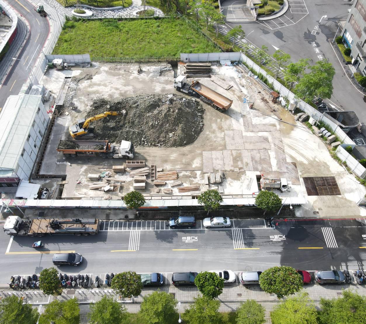
The project is carefully designed for elderly to enjoy retirement life which provide life care services, smart medical care and diversity activities. As Construction Team, we delivered the construction process.
My main duties is to produce the construction drawings and lead the weekly clash review meeting with the architect and client. Due to the first attempt using the Autodesk Revit by the company itself, I assisted the developement of the working process, template and family library to transform to the BIM working system. I also Involved in site inspection for other site and coordinated with BIM consultants to run the clashes detection.
ROLE
CONTRIBUTION
CREDIT
Jan. 2023 - Aug. 2023
Residential Project Sampo Group
C.Y. Lee & Partners Architects / Planners
Construction Engineer / BIM Engineer
· Analysed the architectural drawings
· Led the weekly clash review meeting with MEP engineer, architect and client
· Assisted with construction management and quality control
· Developed the construction drawings
TOP Construction Co, Ltd. (Confidential)
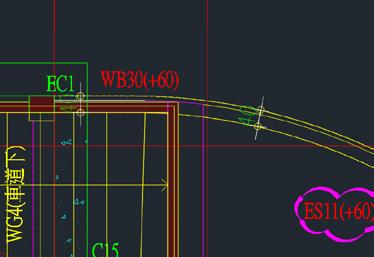
筏式基礎(見下)放樣施工平面圖
1.本圖面以絕對高程GL-1640為相對高程±0。
2.本圖面單位:cm
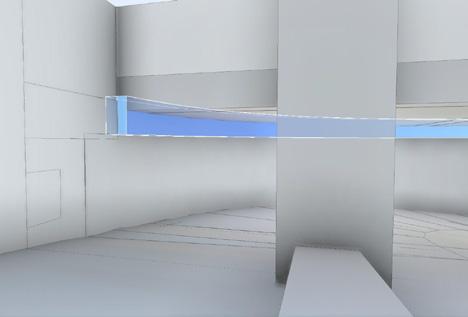
During the weekly clash review meeting, I brought out the results for the clash detections, based on the 3D modelling (Autodesk Revit). It contained the issues such as stucture, route of pipe, clear height for the regulation compliance...,etc. The relavant party have to response for clarification or adjustment, signed by the architects and clients, to proceed the construction drawings.
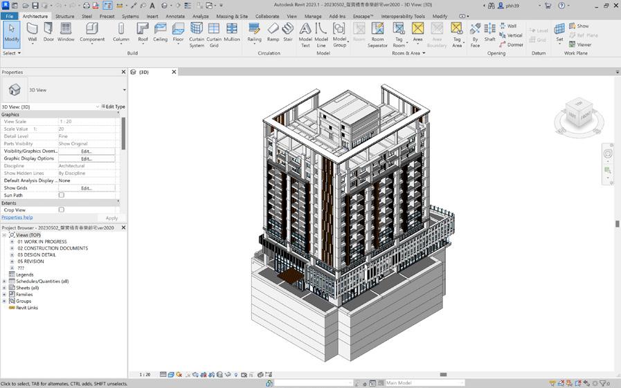
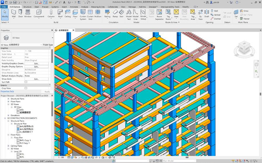
Following the design drawings from the architects, I integrated the information from M&E, structure, and landscape design together to define the Structural Slab Level (SSL) and Finished Floor Level (FFL), and the clash detections. For those details required the awareness, I produced the section cut to show the dimensions for the worker.

Due to the first attempt using the Autodesk Revit by the company itself, I assisted the developement of the working process, template and family library to transform to the BIM working system. This is the experiment project for the company, therefore it ran both way of traditional AutoCAD progress and BIM progrss at the same time to learn from the practical. Following the experience of coordinating with the BIM consultant, I created the concept of Task Information Delivery Plan (TIDP) to manage the information deliverable, and tracking the RFI for the information modelling. CONSTRUCTION DRAWING
TYPE
CLIENT
DESIGN TEAM
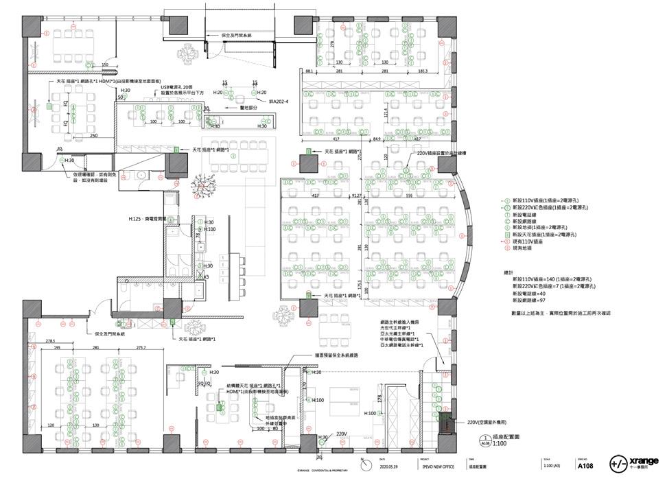
This is the first project that I primary managed for the whole design progress. I first had a meeting with the client to understand the project requirement and brief, defined if there is any material that could be reused from the original office. I was later responsible for the design drawings and construction drawings. To make sure the design went as expected, I utilised the 3D modelling to simulate the results and lighting effect for the decision-making.
When it comes to the construction stage, I collaborated with the contractor and went to the site regularly. I not only gained the experience from the practical project but also built up the connection with professional workers, such as painters, plumbers, and electricians, who were teaching me patiently during the process.
ROLE
CONTRIBUTION
CREDIT
Interior Design Project
IPEVO
XRANGE Architects
Designer
· Developed the design layout and analysed the design strategy
· Conducted site survey and understanding the requirement from the client
· Responsible for design drawings and simulations
· Responsible for the construction site management
· Collaborated with contractor to deliver the design to the client
XRANGE Architects (confidential)
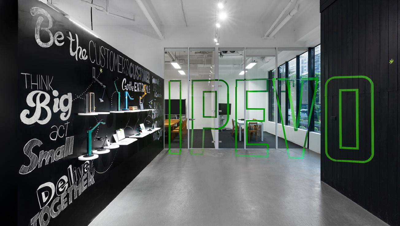
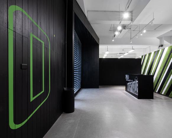
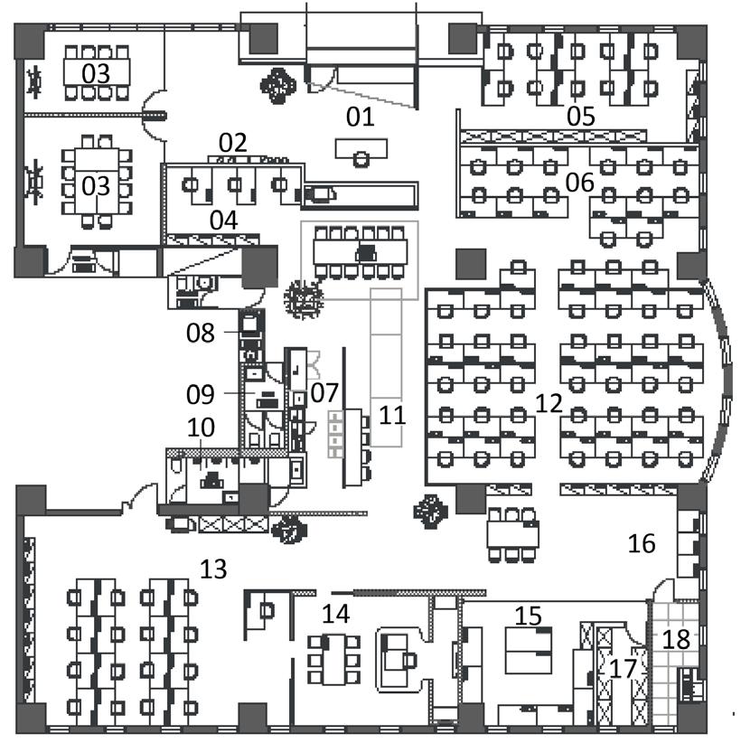
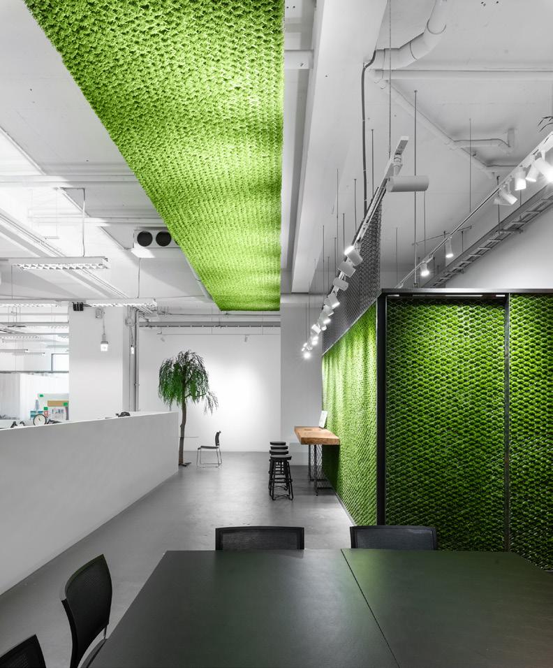
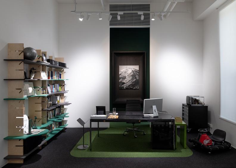
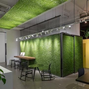
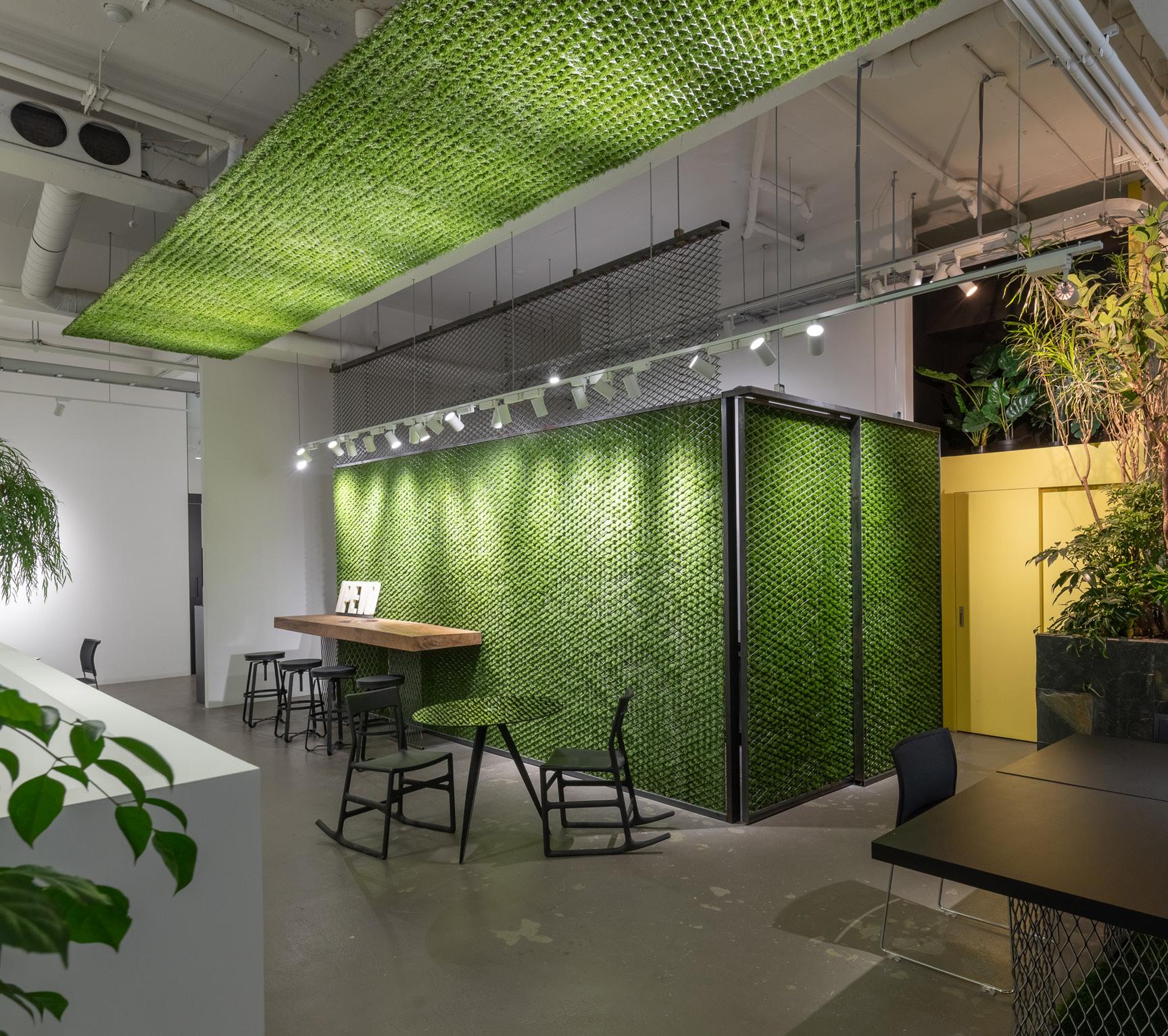
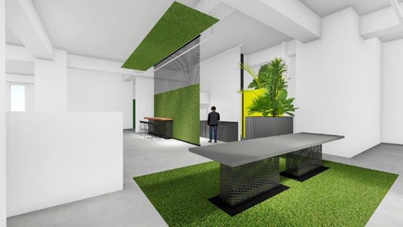
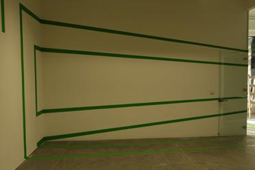
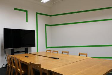
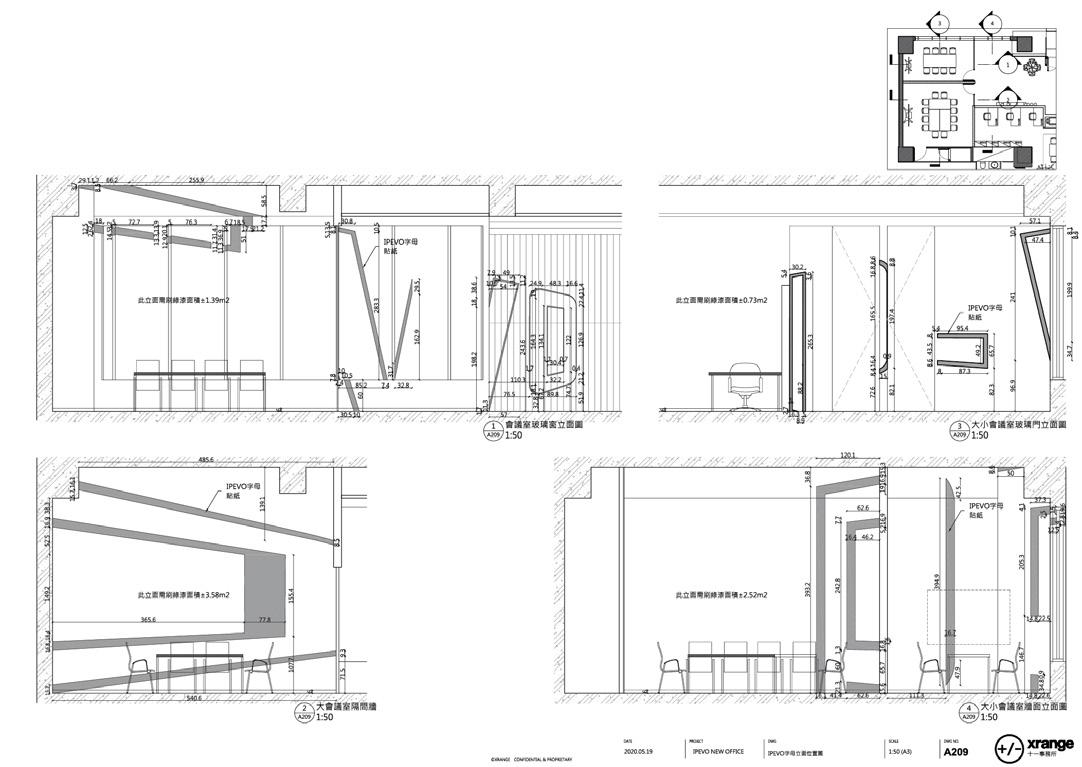
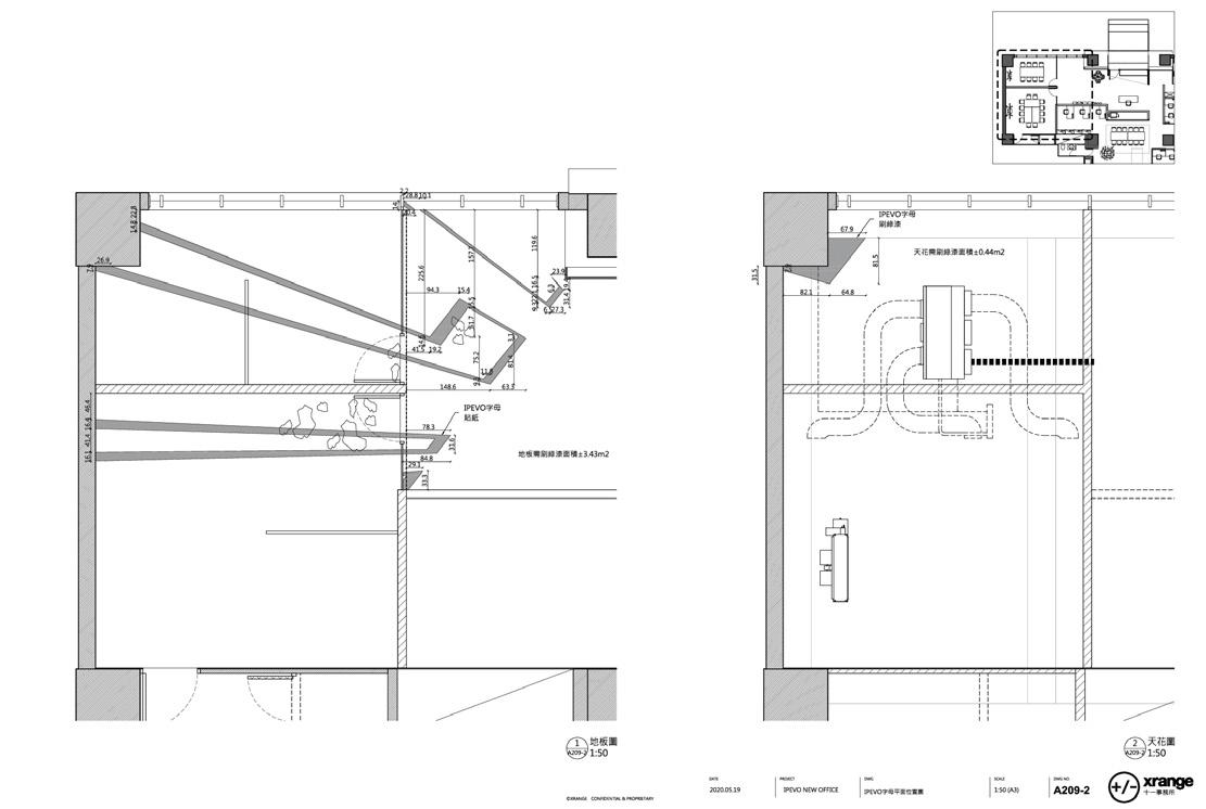
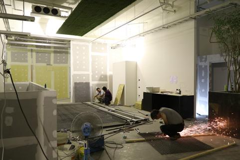
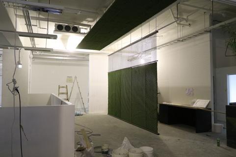
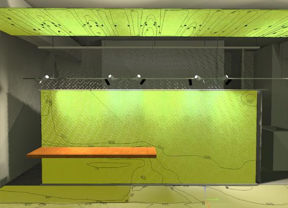
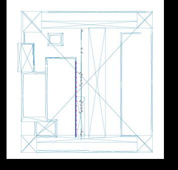
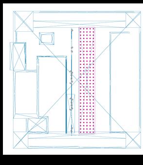
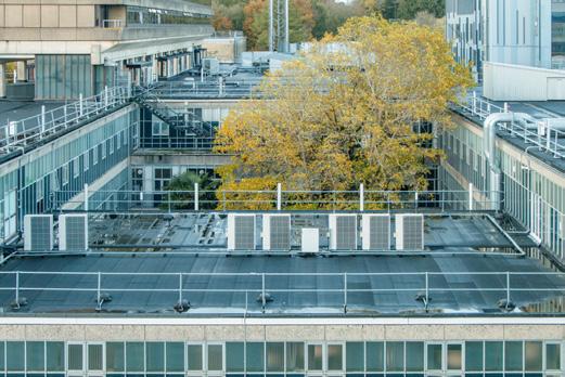
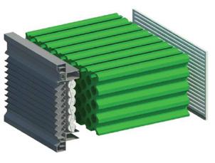
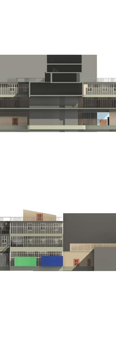
For the new corporate headquarters of IPEVO Inc, the industry leader in education technology, we designed a vibrant, high contrast color blocking interior in green, white and black with multiple plays on visual perceptions in homage to the company’s document cameras for teaching or demos and their concept driven by the phrase “see what I see.” In the space, expanses of turf hovers in expanded metal and a logo fragmented into space, alongside elements that reverse weight and depth expectations.
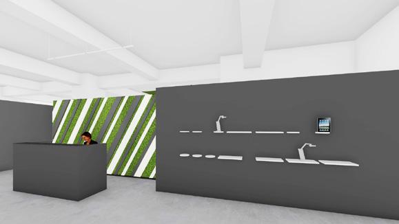
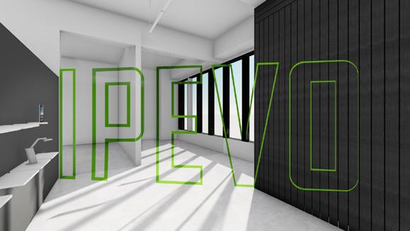
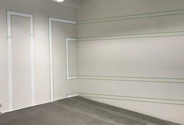
Combined with three different materials, paints, carpets and cutting sheets, the corporate logo is fragmented and dispersed onto windows, doors and walls of conference rooms at the far end of the space, its entirety only visible from one specific spot at the reception desk. I made a 3D model layout for the test and for the contractor, While it is diffecult to guarantee the accuracy. In the end, we spent a whole day laid out ourselves with tapes by projecting the logo onto the surface, and made sure the right coordination between three different contractors.
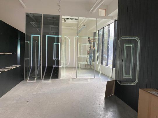
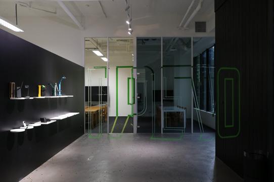
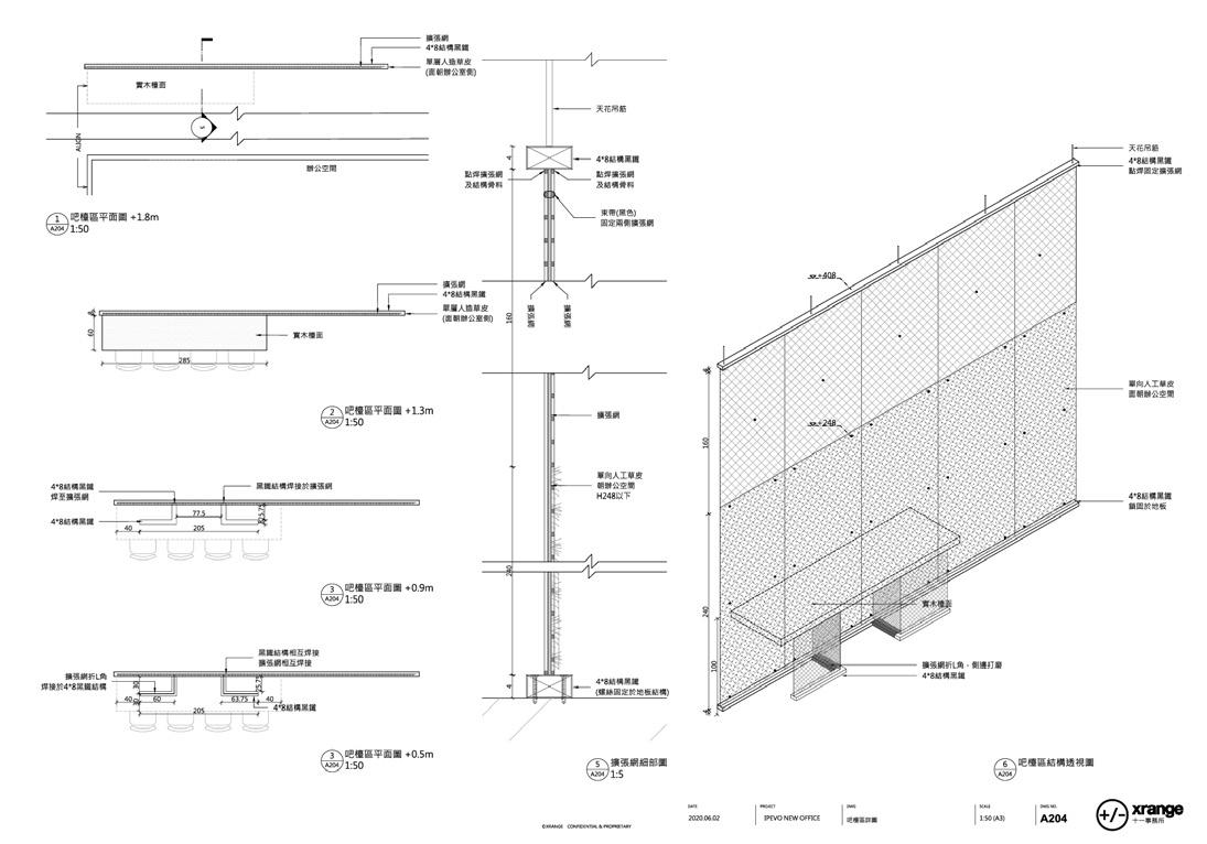
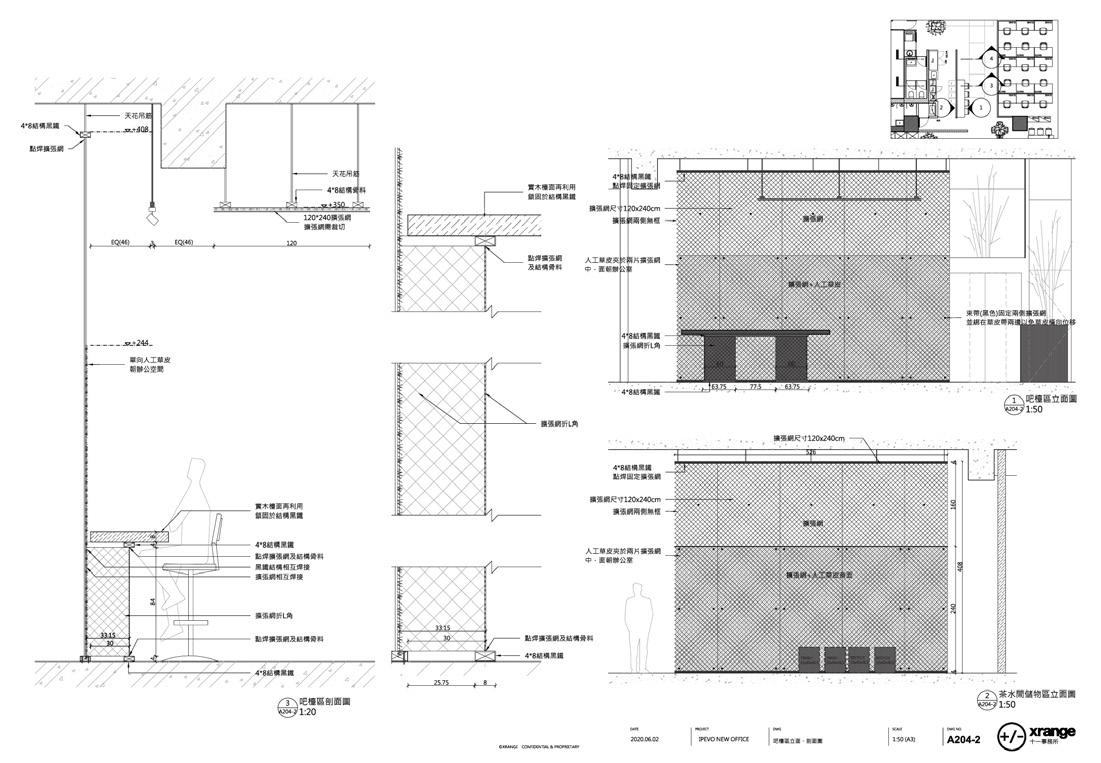
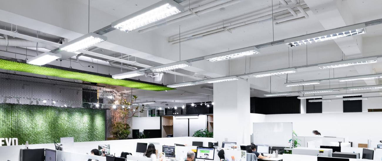
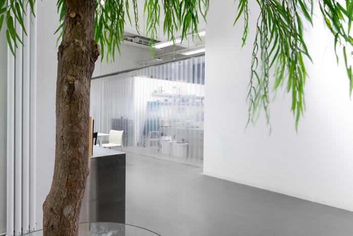
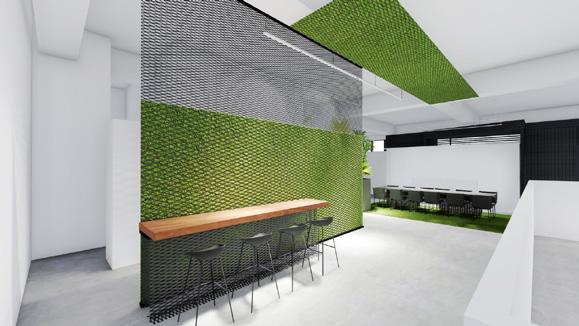
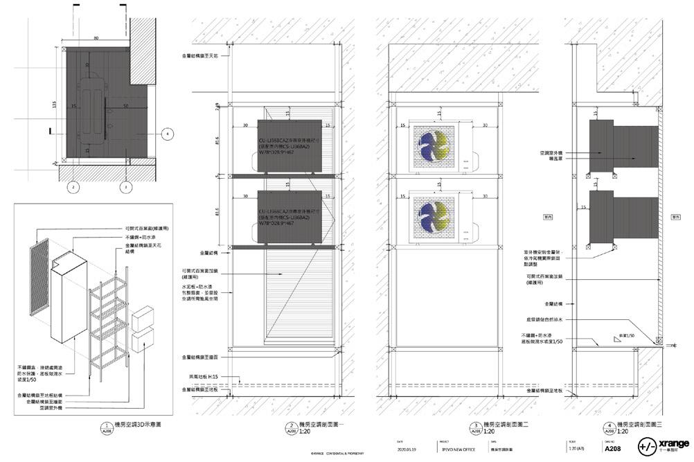
Continued the same language in the previous office of client, we created a central green box enclosing the staff kitchen and service areas to mark the communal core. The green enclosure is created by sandwiching turf between expanded metal sheets which are used as both structure and “frame” for the turf; a paper thin effect that loats the turf aloft. The loating turf, a large built-in planter box for real trees, clerestory shelves for artificial foliage and glass tables supported by real tree trunks together created a mixture of real and perceived green aura that surrounds this central space.

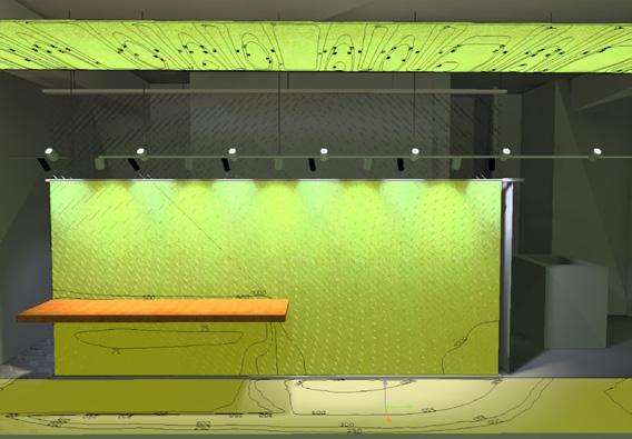
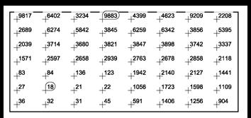
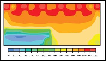
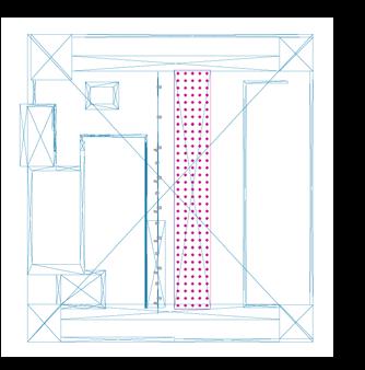
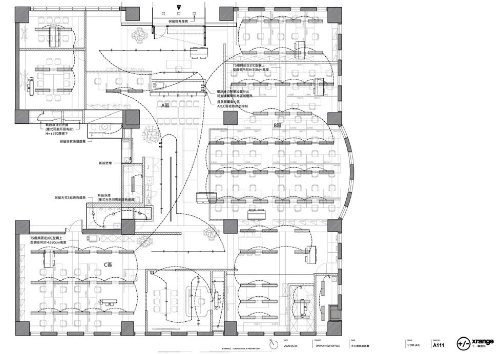
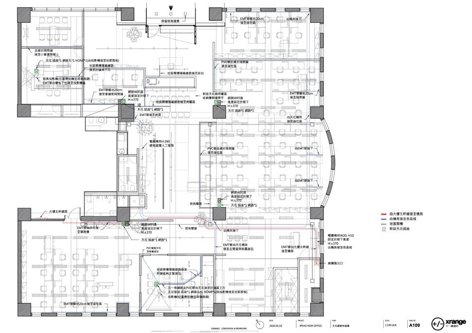
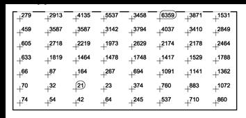
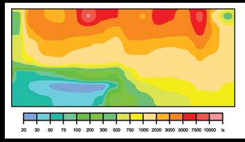
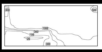
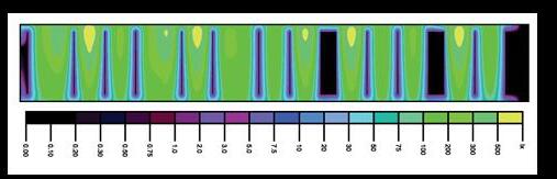
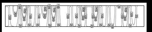
ILLUMINATION ANALYSIS by DIALux
To standardise the lighting we use in this project and reused some light the client used to have, we chose the track light for all public area. When I tested the lighting effect on site at first, it was not efficiency and did not achieve what we expected. Therefore, I started to do the simulation by DIALux to balance the light on the expanded metal and grass. I tried to craeate more contrast for both on the wall and ceiling part. It helped me for not only on the result but also the basic knowledge about lighting and the software I can use.
After a few testing on different schemes, I adjusted the lights by myself following the simulation result, and the architect approved the final result in the end.
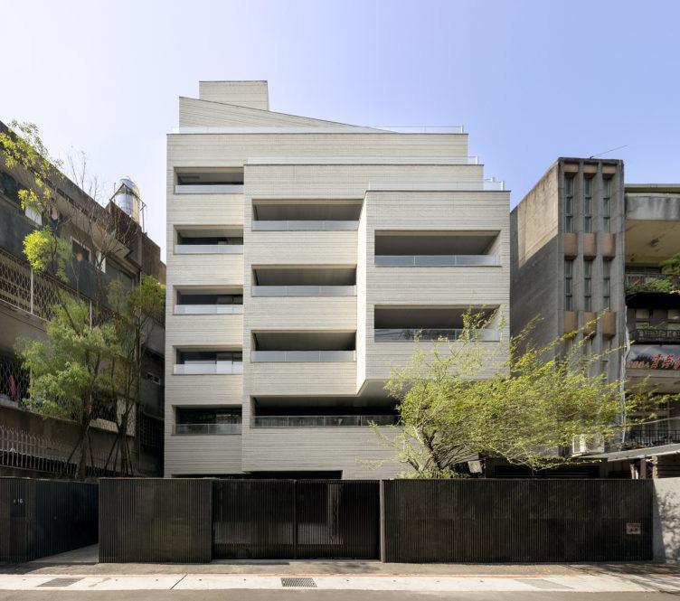
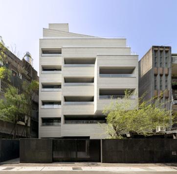
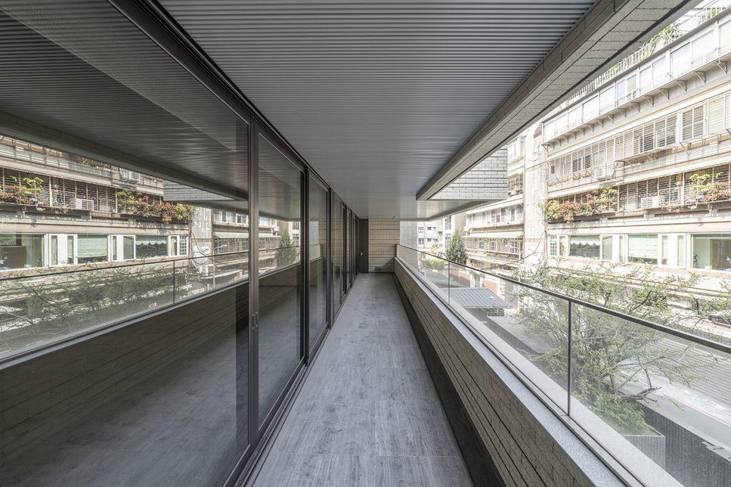
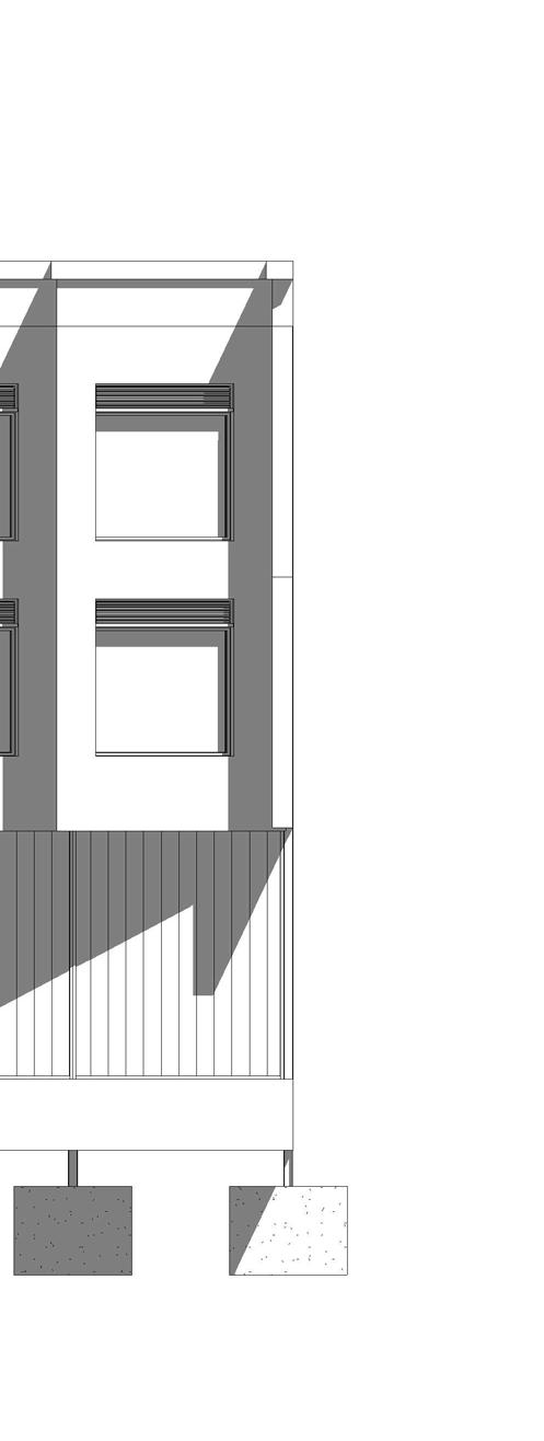
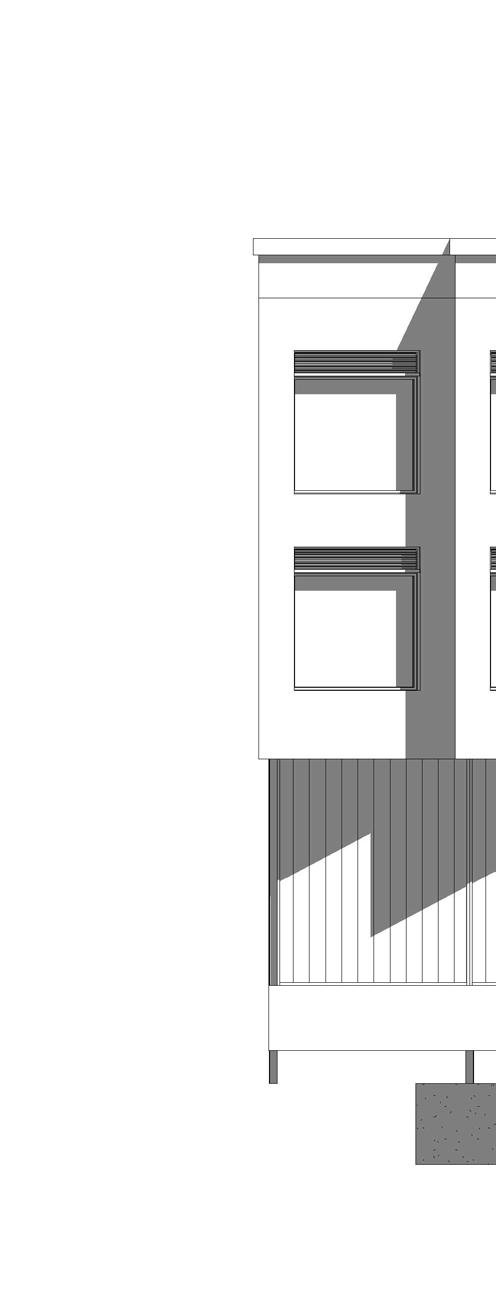
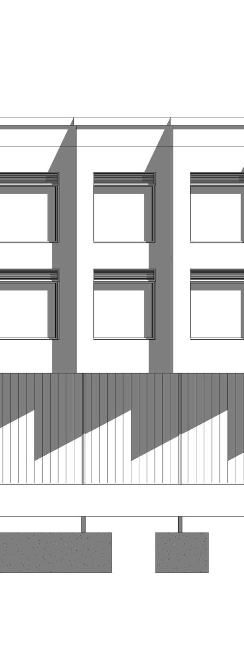
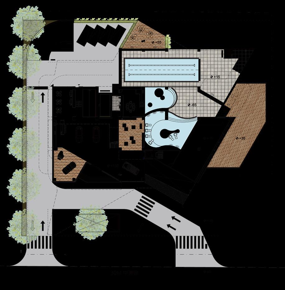
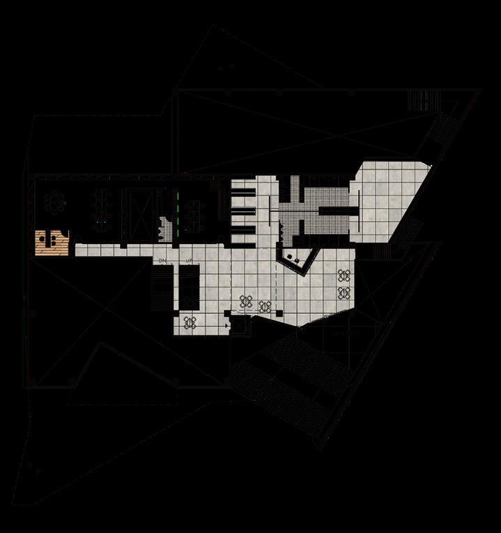
The design is to upend the ubiquitous convention for housing in Taiwan, which has given rise to the prevalent practice of exposing the concrete structural frames on the outside envelopes of residential buildings. A hybrid structural system is developed, which creates a large column-free residential unit interior of 12 m x 11 m. The units’ service areas are furthermore integrated into the core, giving the units a squarish column-free open plan and a north-south transparency best for lighting and natural ventilation.
TYPE
CLIENT
DESIGN TEAM
ROLE
CONTRIBUTION
CREDIT
Jan. 2019 - Mar. 2021
Residential Project
Shihlin Development Company Limited
XRANGE Architects
Designer
· Assisted with the detail design and shop drawings
· Involved in the site inspection to discuss the interface between different materials
· Assisted with the material decision and tiles layout by utilising 3D simulation
XRANGE Architects (Confidential)
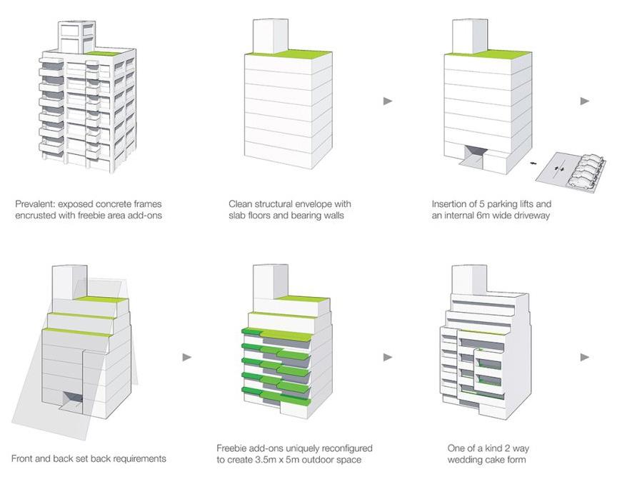
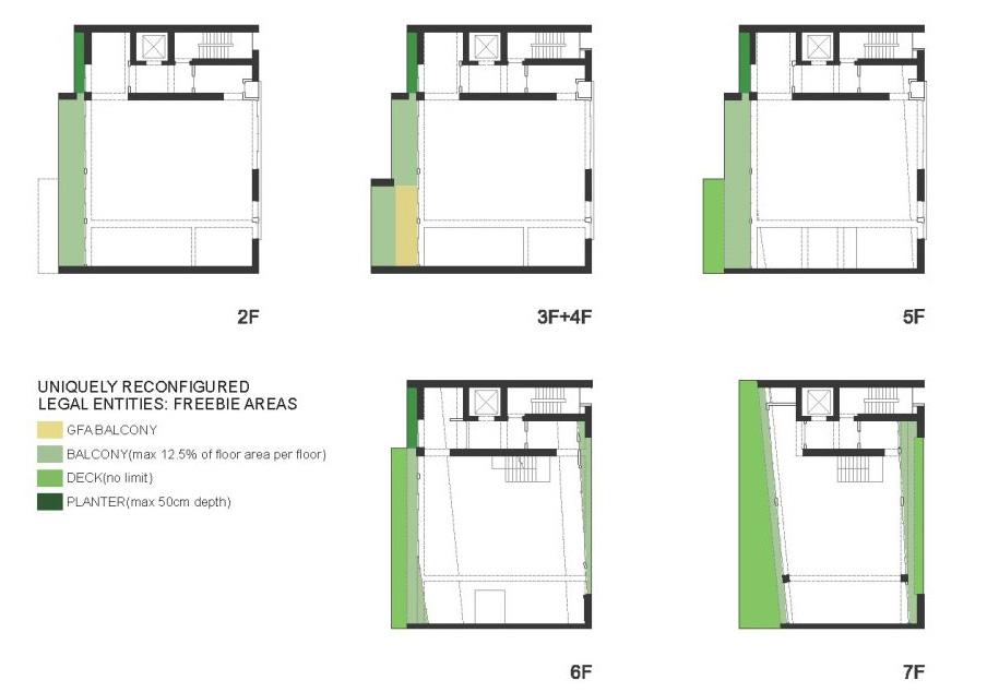
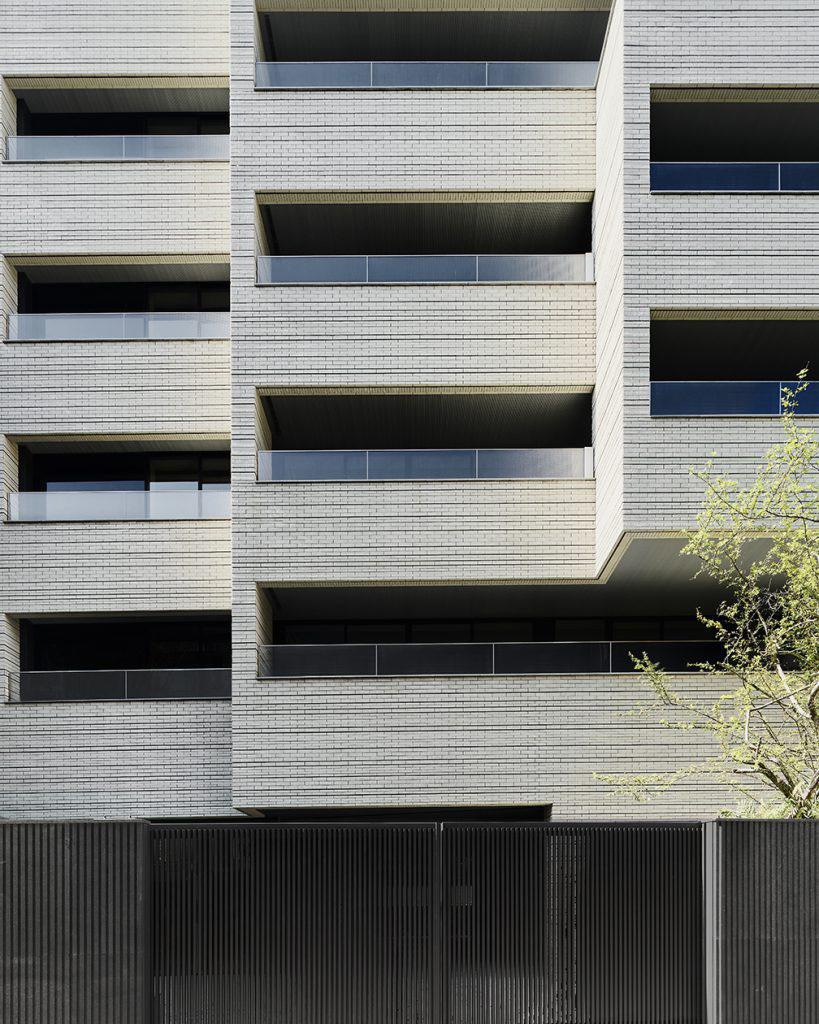
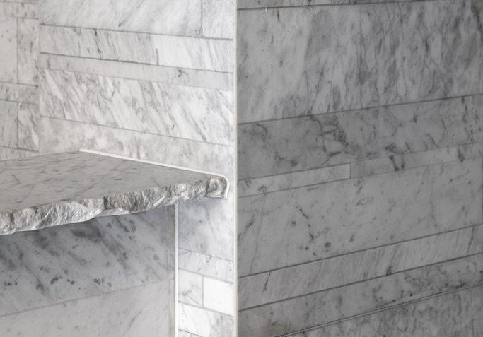
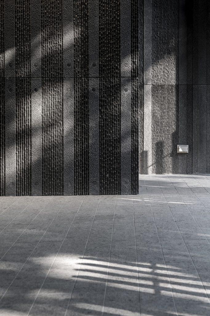
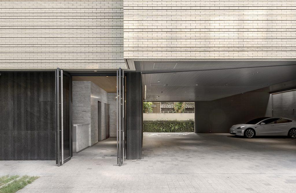
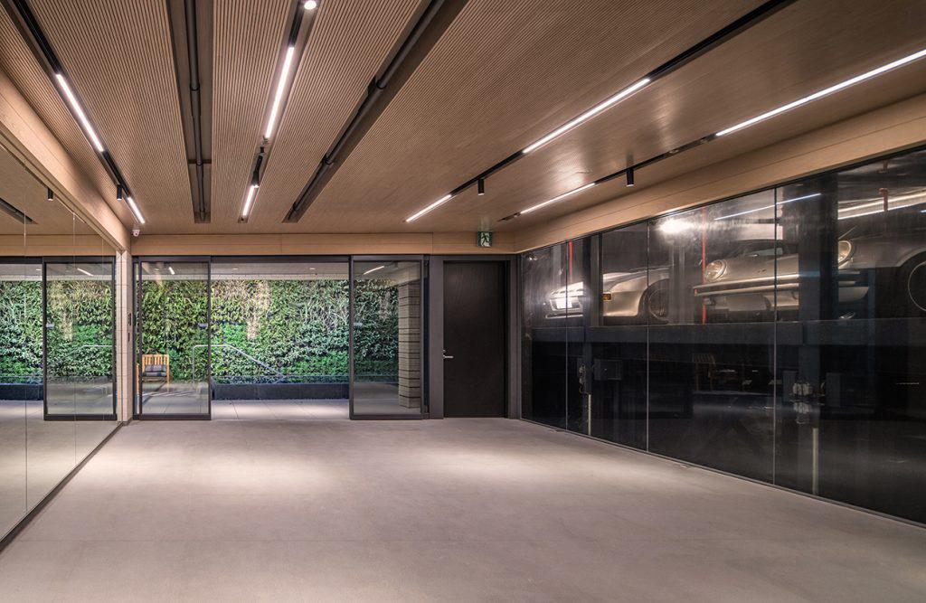
The 60cm deep flower bed, 200cm deep balcony and 350cm deep terrace are merged into a stepped form in plan that stretches over the entire 17m wide street front of the building. The reconfiguration made possible a 3.5m x 5m outdoor living space, creating a new housing layout previously unseen for dense urban living. The units’ service areas are furthermore integrated into the core, giving the units a squarish column-free open plan and a north south transparency best for lighting and natural ventilation.

The creative solution of this urban housing project came from direct design responses to existing urban phenomena and rethinking legal constraints. Through the use of an ad hoc structural hybrid paired with concise geometric strategies, the unique stepped architecture form of the housing project achieves a striking purity, and created unparalleled benefits for both developer and housing occupants.
I assisted the development of the material interface of the stone cladding, automatic door system, tiles and the lift on the ground floor. To keep a clean appearance, we make sure the mechanical devices position properly, combined with the metal panel, for the maintenance. I also coordinated with the supplier, developed the details drawings of the support brackets and stone tiles, and made sure the size of the tiles and structure support correctly, and the gap between cladding panels away from the human eye level.

Bath, United Kingdom
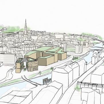
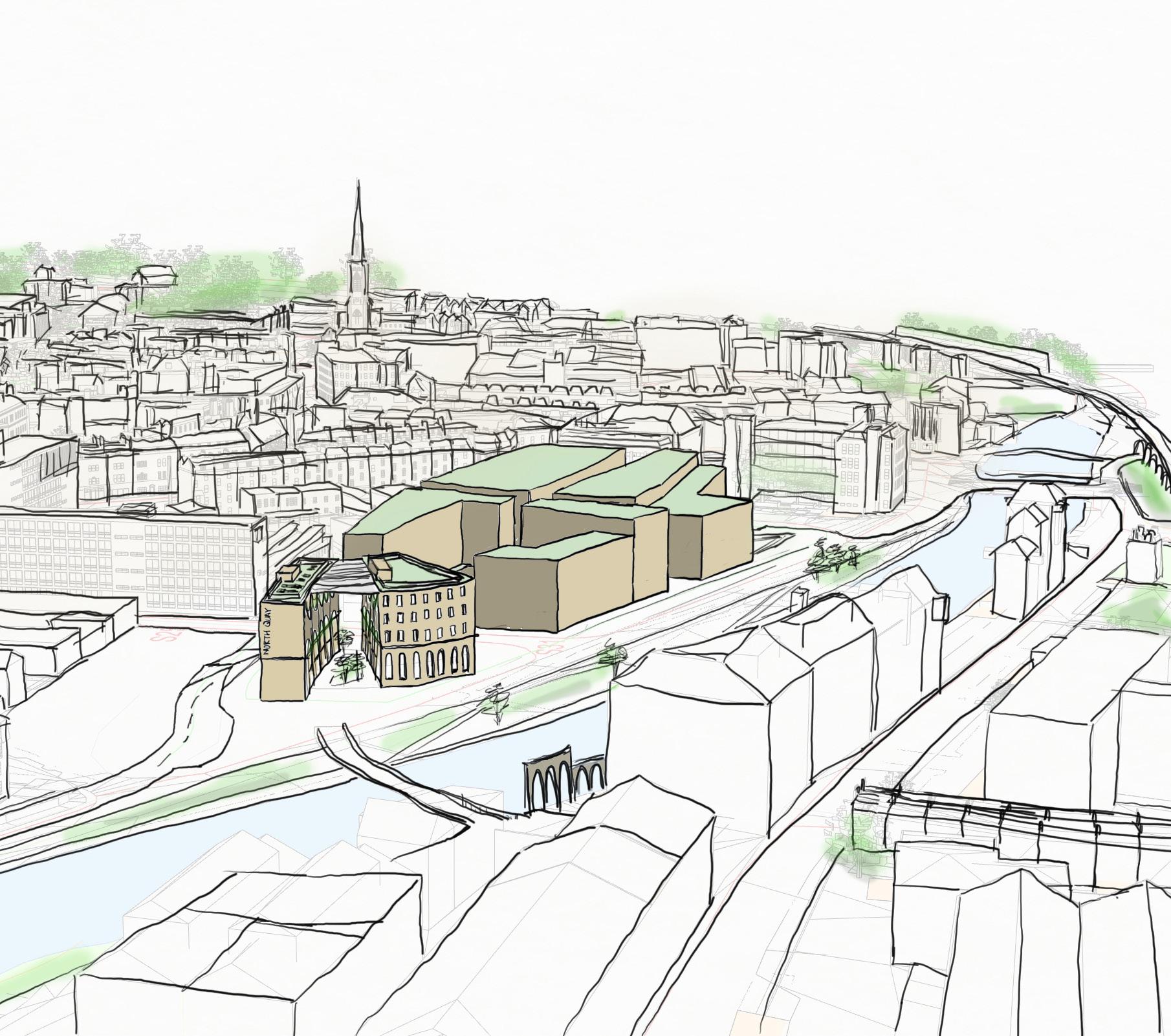
The Bath and North-East Somerset (BANES) Council recently acknowledged that there is a climate emergency and is seeking to make the county carbon neutral by 2030. The BANES regeneration strategy establishes redevelopment zones, one of which is the Bath City Riverside Enterprise Zone, where the Bath Quays Project site is situated. The scheme should achieve the following requirements:
1. Office and retail
2. A choice of low and/or high-budget hotel facilities for tourists.
3. Residential accommodation of different sizes to address specific social and climate justice needs, with at least 25% of the housing units for ex-prisoners, and 25% should be affordable for the social justice.
TYPE SUPERVISOR
ROLE
CONTRIBUTION
MSc Design Project (Group)
Dr Kemi Adeyeye
Dr Ricardo Codinhoto
Sarah Gibson Architect
Lead Designer
· Coordinate with student from:
MSc Environmental Design
MSc Conservation of Historical Building
MSc Innovative Structural
MaterialsArchitectural design and sketching, Floor planning, Technical architecture and facade analysis, Detailing spaces and materiality, Interface analysis, Portfolio layouts, Regulations compliance


The flood map reveals that the site is in flood zones 2 and 3, indicating a high probability of flooding. Therefore, it is necessary to conduct a flood risk assessment for the site before any development takes place, and appropriate flood mitigation measures must be put in place. Traffic congestion is the major noise source observed and this pollution on site is through the Corn Street road and the junction from railway route. The noise map shows 65 to 70 dB at the junction and upto 55 to 60 dB near Corn Street road. According to the BREEAM, the maximum noise level for mixed use buildings should be between 40 to 50 dB depending on the functionality of the space.
For the proposed site, Corn Street is transformed into underground underpass which helps to mitigate the noise levels as the vehicular noise is diverted.


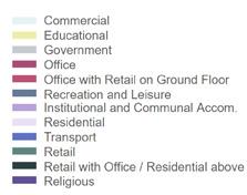


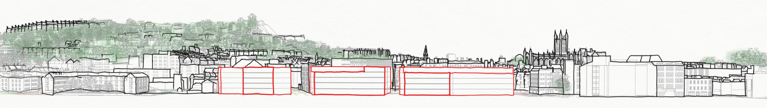


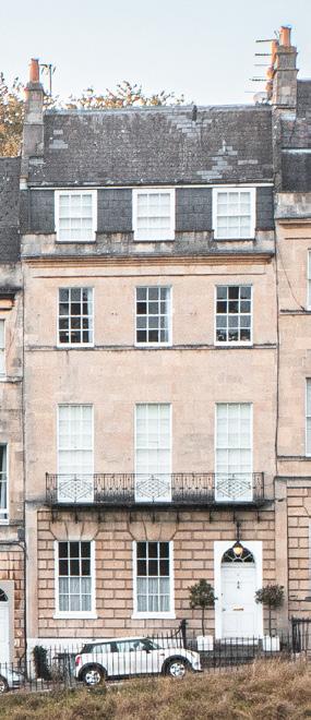
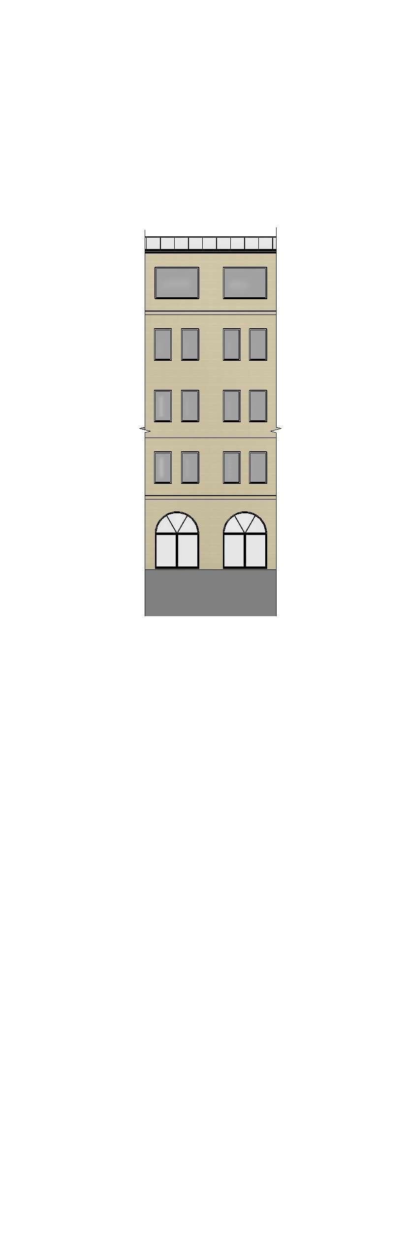
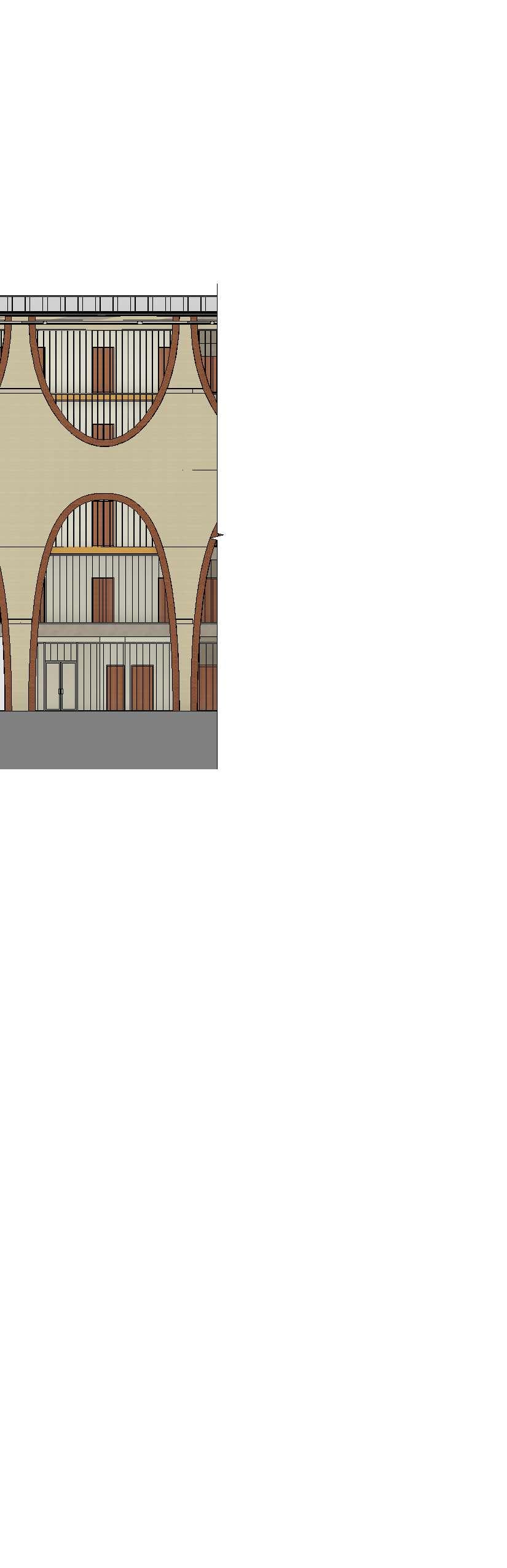
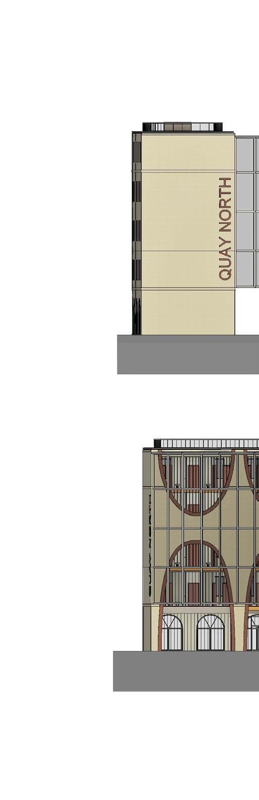
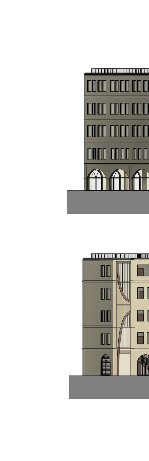
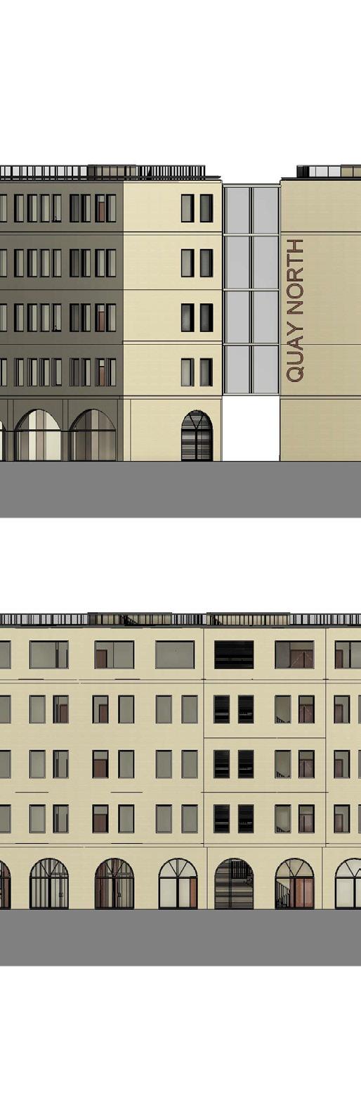
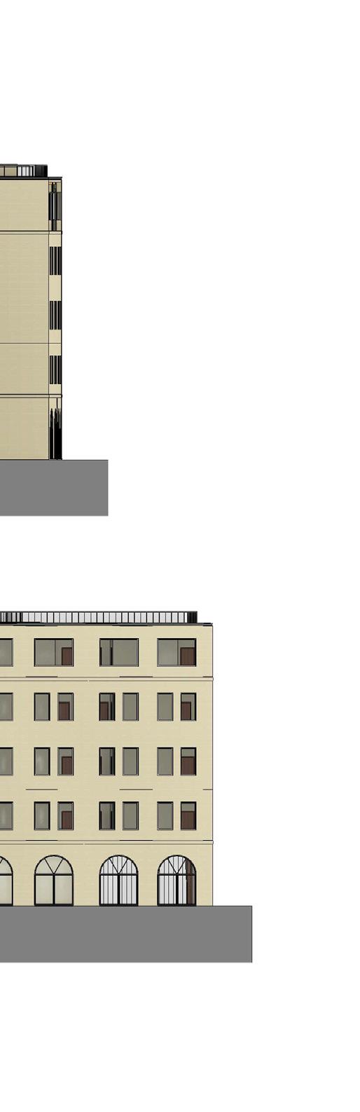
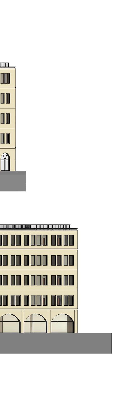
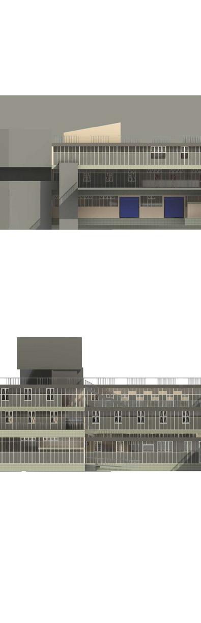
In summary of design specifications, the facade facing the city will be clad in warm, honey-colored Bath stone. The architectural propotion and scale will be divided into three parts, ground floor, middle part of building, and the top follow by the Ancient Greek temples. The building height follows the recommends from BANES Character Area appraisal for 19 meter and five storeys.

For the internal facade in between atrium, the industrial arch and red brick masonry represent the site’s working class history. The climbing plant and privacy screen could also ensure the privacy for residents and improve air quality.


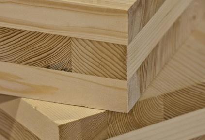
• Less carbon emission 37% less carbon than a concrete structure of the same size.
• Provides fire protection CLT panel is a large, compressed, and solid mass of wood, it does not ignite easily. When exposed to fire, the outside layer of the material may char, but it can receive further protection by applying fire-rated paint specifically designed for wood.
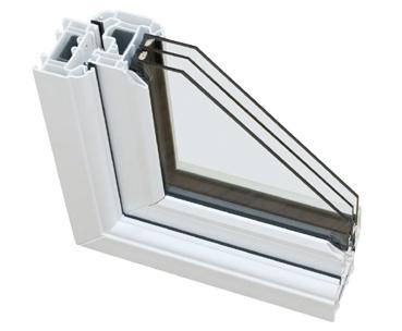
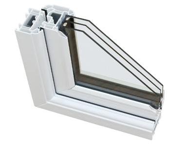
• Reduced heat loss and cold drafts
There is air space between each panel of glass that help reduce thermal transfer, and keep the space more comfortable and efficient year-round.
• Reduced noise and sound transmission Triple pane windows has enhanced soundproofing capabilities as a result of the additional layer of glass. . The air in between also contributes to the attenuation of external noise.

• Reflect the fundamental material in Bath’s classical architecture
• Long term energy savings PV Glass generates free and clean electricity thanks to the sun, turning buildings into vertical power generators. Plus, it is no different from installing conventional glass.
• Natural illumination and selective filter
PV Glass lets natural light go through. It offers different visible light transmittance levels, up to 30%.

Treated floor area (TFA)
Thermal envelope area
Form factor (envelope area / tfa)
Average U-Value
Space
Space
m² Includes external walls, windows, roof and ground floor
A low energy house would typically aim for a value ≤3
Carbon footprint
Embodied carbon 700 kgCO²e/m² Requirements = 500
Operational carbon 400 kgCO²e/m²
Accounts for the lifetime of the building (100 years)
This final result is based on the use of natural ventilation and the integration of various energy recovery/ generation methods. The energy generation or recovery technologies applied here are:
• Reduce the U-value of the building envelope
• Minimise the thermal bridges
• Reduce the infiltration rate
• Increase the heat recovery(HR)
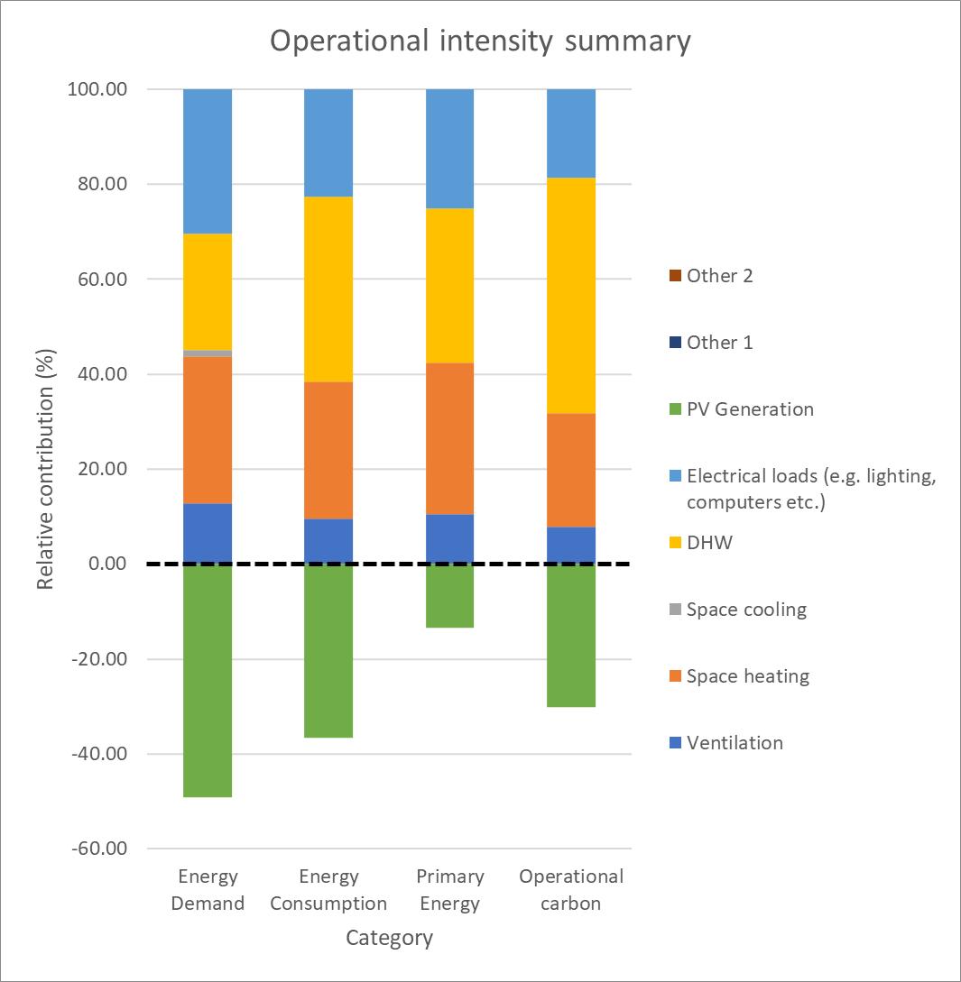
Due to the building produces 4 kgCO²/m²(TFA)/year because of the DHW requirement, even if we install the PV panel on the roof and PV glass on the roof and on the west facade, it could only reduce the energy consumption but not be able to reach the Net zero.
During the ZEBRA model calculation, to minimize the heat loss during winter and to meet the heat demand requirement in the winter for the Passivhaus energy performance standard, which is set at 15kWh/m²/year, the key effect point is the ventilation system during winter. Therefore, to meet the standard, the MVHR system is the only solution even though there is energy consumption.
In conclusion, the final decision is to use the natural ventilation by user control during summer for cooling purposes and MVHR system in the winter to enhance the heat recovery.
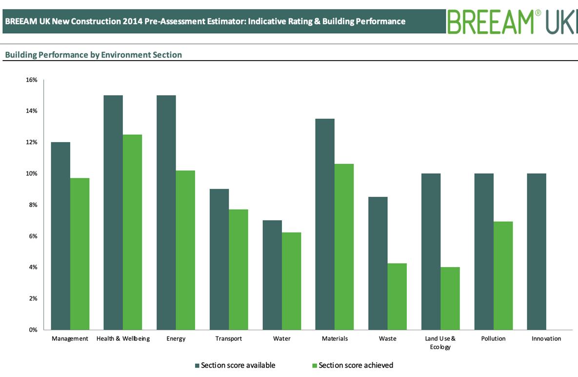
A 70% is required to achieve BREEAM Excellent. We achieved 72.1% using especially conservative estimates in the areas of energy, water, land use and ecology, with no innovation points.
Bath, United Kingdom
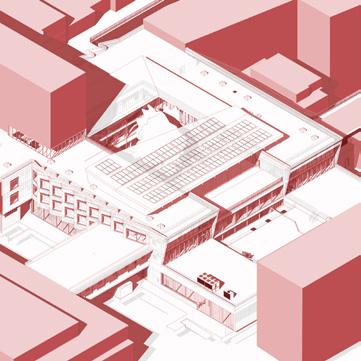
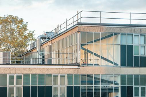
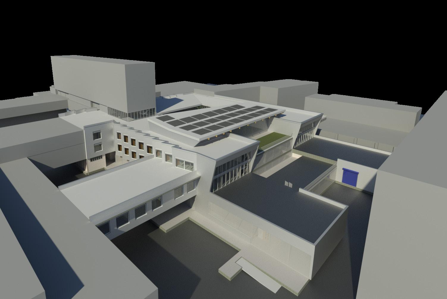
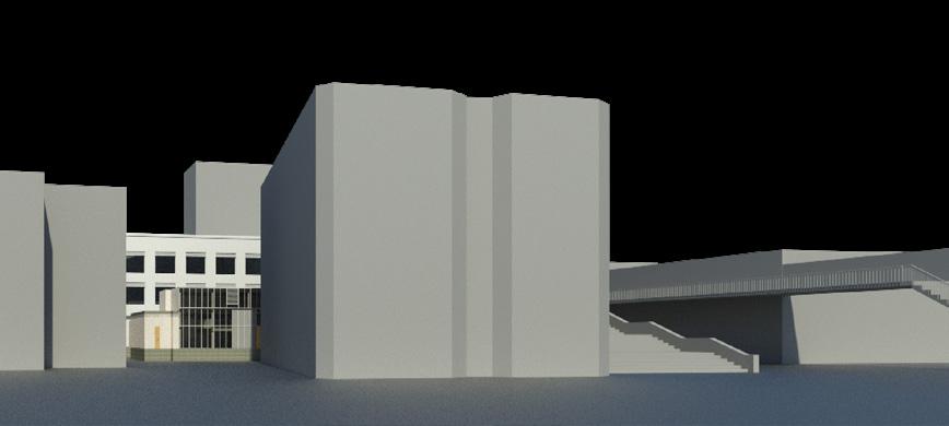
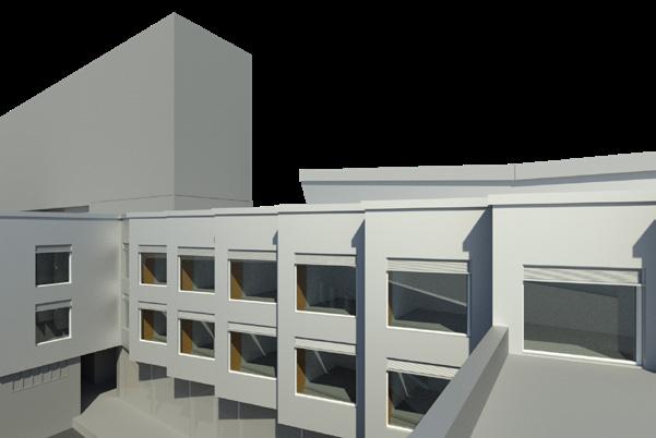
The University of Bath is looking to improve the low carbon façade performance on campus building: 4 East. The project requires a feasibility assessment and propose new façade solutions to improve natural ventilation, daylight, acoustics, and thermal comfort for the building users, with conducting environmental performance assessments to confirm compliance with the current building regulations. Based on the Autodesk Revit software, the modelling includes the development for the architectural, structural and MEP solutions in phases. The project objective includes the following:
1. Improve the building envelope including the roof and façade system
2. Courtyard design
3. Compliance with the regulations&standards
TYPE SUPERVISOR
Oct. 2023 - Jan. 2024
MSc Design Project (Individual)
Dr Kemi Adeyeye
Dr Ricardo Codinhoto
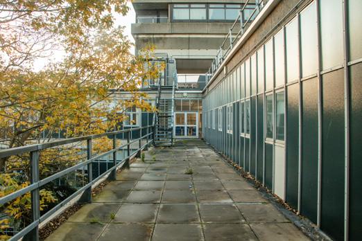
Internal Factors
1. Courtyard in the centre of building
The courtyard provides the possibilities for ventilation and daylight.
2. Easy access to the building
Connects to 2E ,6E and 8E, and accessble from each side of the building.
3. Flexibility of the building
The structure is detached from the building, offering flexible reconfiguration of the layout.
1. Limited access to the courtyard
The only way to enter the centre courtyard is through the ground floor, where the majority of the workshops and laboratories are located.
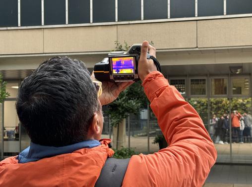
S2. Inefficient façade system
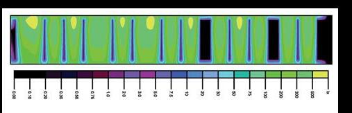
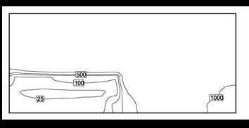
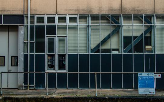
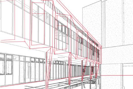
The façade system has poor thermal and sound isolation. The thermal image displayed in figure 11 shows the loss of heat from the façade system.
WExternal Factors
Opportunities
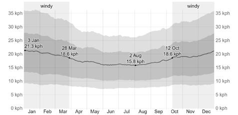
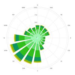
1. Primary wind direction from south-west corner
The corner allows wind flow to the site which help to improve ventilation.
2. Green view from south-west corner and courtyard
Optimise the green elements that promote both physical and mental well-being in humans.
OThreats
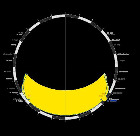
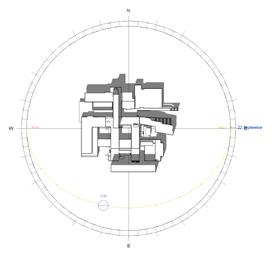
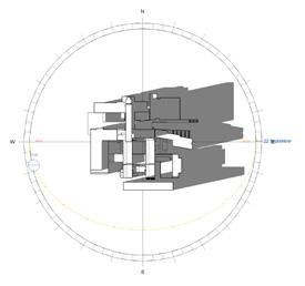
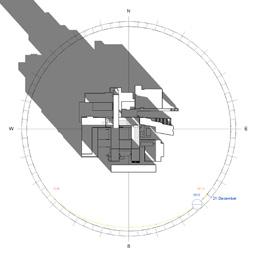
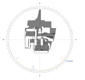
1. Over shadowing from the surrounding
The reduction of daylight is primarily caused by overshadowing from the adjacent buildings during most of the year, except during the summer.
2. Noise pollution from the parade and loading area
The acoustics of the building are significantly impacted by the noise that comes from the parade and the loading area, particularly during peak hours or when there is an event taking place.

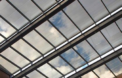
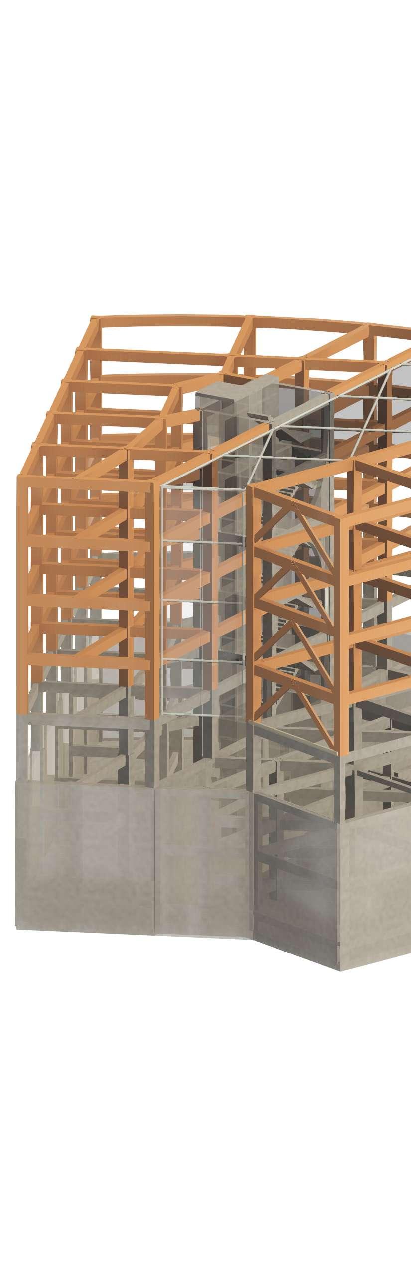
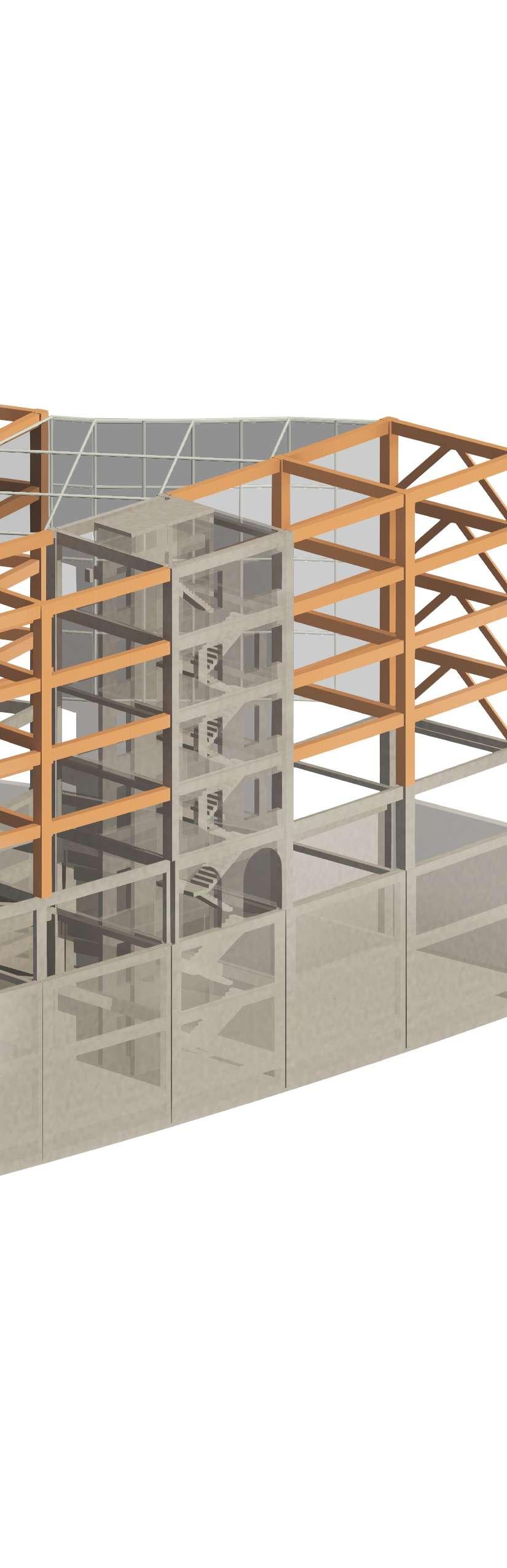
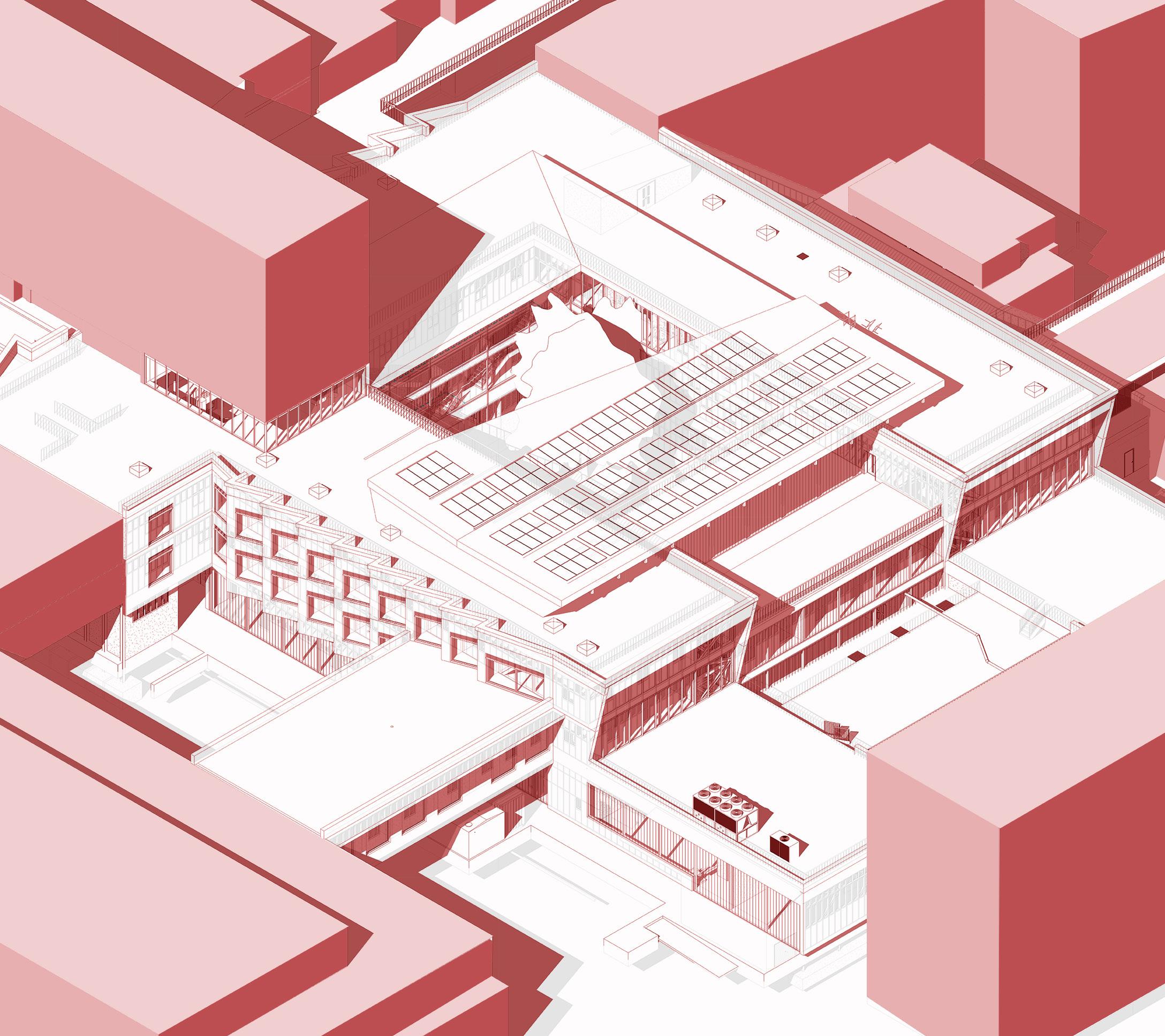
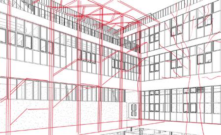
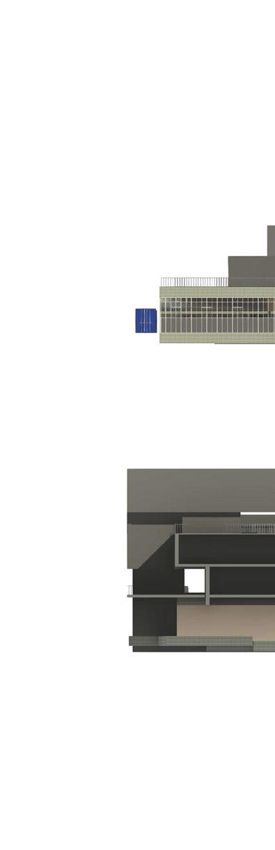
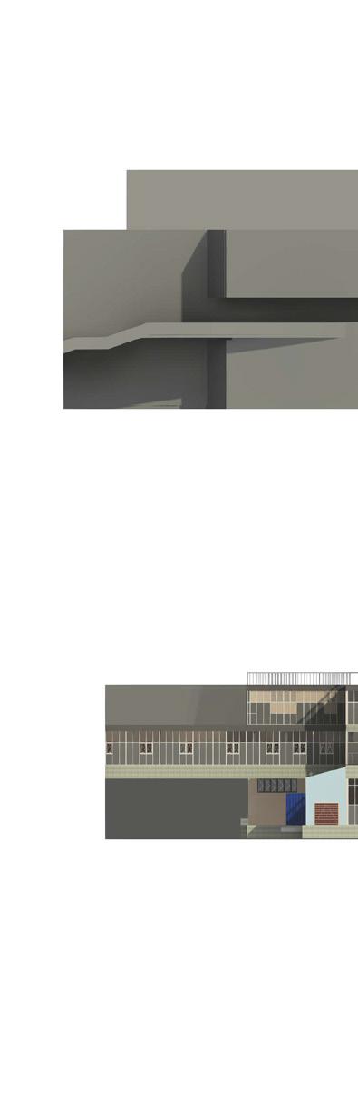
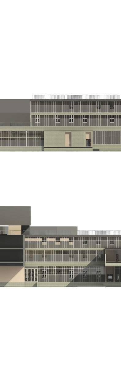
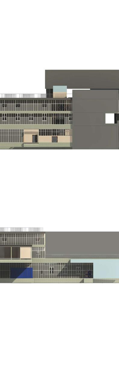
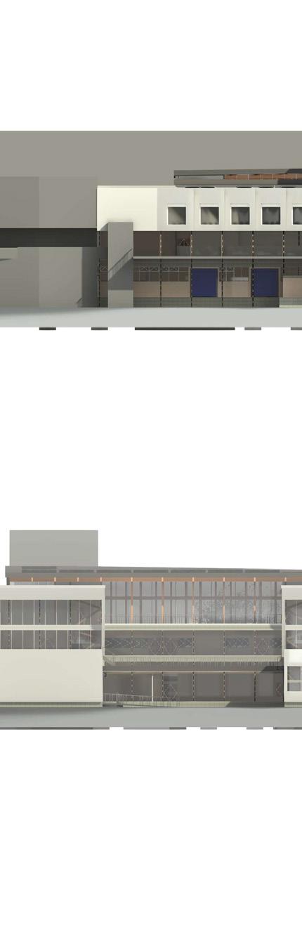
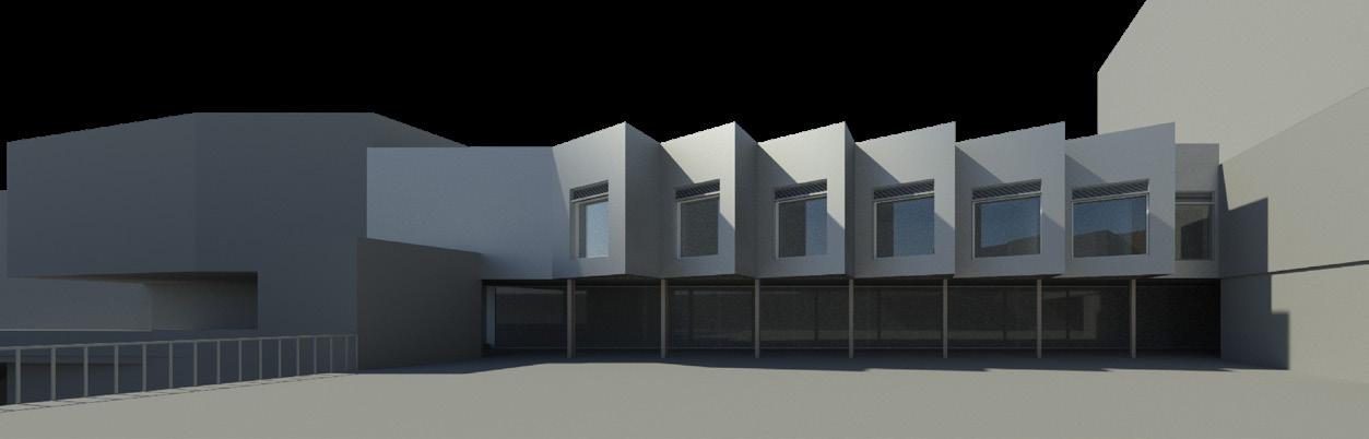
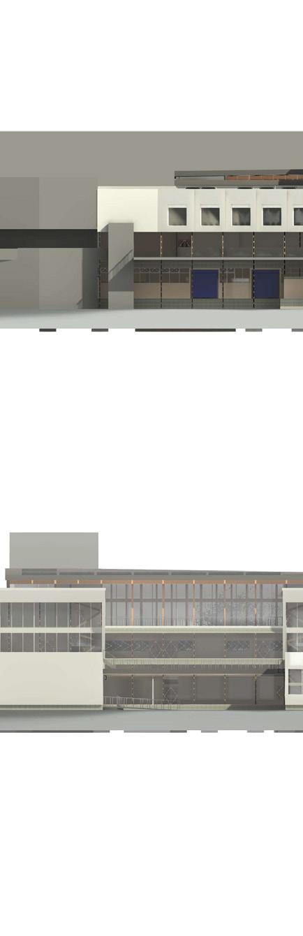
The concept of the system is based on the modular systems, where modules are hung on the original steel structure. The curtain wall system on the ground floor, with 75% transparent polycarbonate panel for the workshops and laboratories, provides the daylight properly and keep the privacy and concentration of working at the same time. The first and the second floor modules are designed to be hung to the original steel structure by the cross laminated timer (CLT) structure at each floor. Once the CLT structure is finished, the insulation
and finish aluminium cladding will be hung on the new structure. The structural integration ensure that the building can incorporate the additional loads due to the self-weight of the modular system, wind loads and the combination of both.


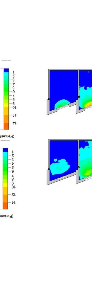
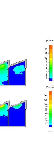
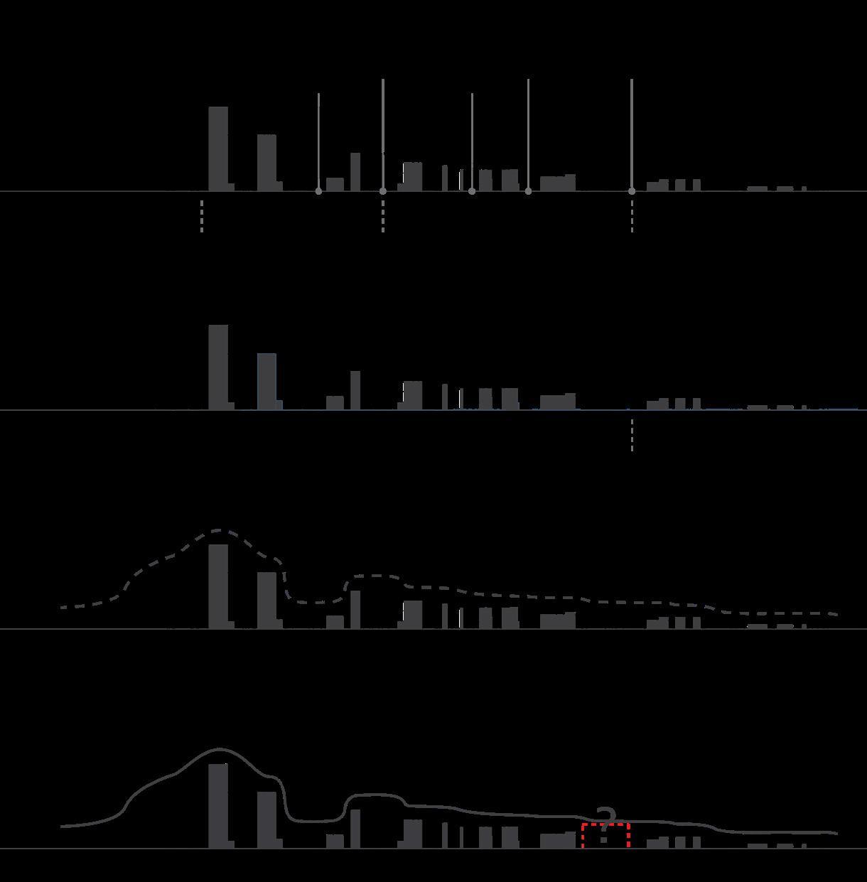
The façade analysis presents the effect of different conditions on the Average Daylight Effect (ADF). The first part shows the different still height align to top/base line with different window-to-wall ratio. The simulation indicates that window align to the top reach higher ADF while potentially get more heat at the same time, align to the right performance better than align to the left. The second part displays various transparency percentages for polycarbonate on the ground floor. The ADF could be up to 27% maximum as the 100% transparent polycarbonate. The final design decision, following by the workplace recommended daylight factor, is 75% transparent polycarbonate with the ADF about 10% for the ground floor workshops. For the first/second floor, considering the installation of ventilation system, 45% opening align to centre/base which performance 2.4% ADF could be the balance of daylight and ventilation.
MATERIAL and OPENING ANALYTICAL COMPARISON


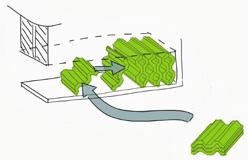
• Retains a lot of CO2
Cross laminated timber, being composed of wood, is an environmentally friendly and renewable construction material that continuously stores carbon in the atmosphere.
• Provides fire protection CLT panel is a large, compressed, and solid mass of wood, it does not ignite easily. When exposed to fire, the outside layer of the material may char, but it can receive further protection by applying fire-rated paint specifically designed for wood.
• Reduced heat loss and cold drafts
There is air space between each panel of glass that help reduce thermal transfer, and keep the space more comfortable and efficient year-round.
• Reduced noise and sound transmission
Triple pane windows has enhanced soundproofing capabilities as a result of the additional layer of glass. . The air in between also contributes to the attenuation of external noise.
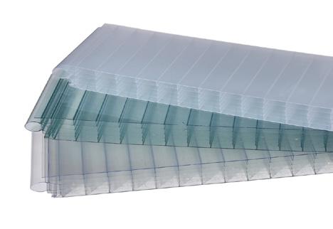

• Thermal performance and natural light
Polycarbonate is naturally heatresistant, and it can be combined with flame retardant materials without significant material degradation. Similar to glass, a polycarbonate sheet can allow access to natural light.
• Light in weight
Polycarbonate sheets are twice as light as standard glass. This makes it very easy to work with, especially for a project such as installing a patio canopy.


Treated floor area (TFA)
Space
Space
kgCO²e/m² Accounts for the lifetime of the building (100 years)
With the natural ventilation system, the heat gain will be 40-60 kWh/m²/yr containing the electrical loads and estimated number of occupants. A typical UK home has a space heating demand of around 130- 140 kWh/m²/yr. The heat demand for this project is 14.1 kWh/m²/yr. During the ZEBRA modelling calculation, the main challenge is in meeting the heat demand requirement for the Passivhaus energy performance standard, which is set at 15kWh/m²/yr. For the calculation, the key effect point is the ventilation system during winter. The heating demand in the winter for the weather in Bath requires more than the heat gain from the building envelopes, occupants, and electrical loads. The solution for this situation could be:
• Reduce the U-value of the building envelope
• Minimise the thermal bridges
• Reduce the infiltration rate
• Increase the heat recovery(HR)
With the good performace of material for the building envelopes already, the project is not aimed to reach the air tightness for Passivhaus standard. In other words, the proper infiltration rate is acceptable. Therefore to meet the standard, the MVHR system is the only solution even though there is energy consumption. Meanwhile, the natural ventilation during summer is sufficient to meet the standard for space cooling.
Design alternatives comparison from GBS
What if the PV panel area for this project increase?
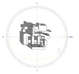
The PV panel area is set about 345 m², 7% of the total roof area, with the generation of energy for 23,444 kWh/yr. Most commercially available solar panels have an efficiency of less than 23%, with an average range of 15% to 20%. In order to meet the net-zero requirement, the PV panel area should up to 60% of the roof area. Based on the simulation, the surfaces that received the most amount of solar insolation are the two new sloping roofs faced towards the south, which is also where the PV panel is located. However, the roof of 4 East does not consistently get sunlight insolation as indicated by the solar study and simulation. Considering the price-performance ratio, it will spend more time and cost more than the energy saving. In other words, increasing the PV panel area is not a feasible option for meeting the goal.
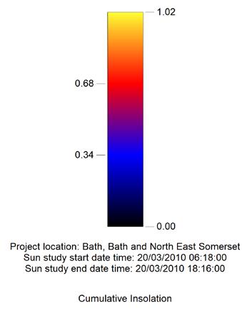
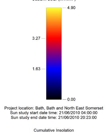
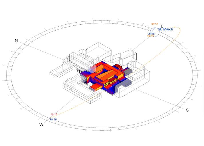
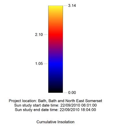
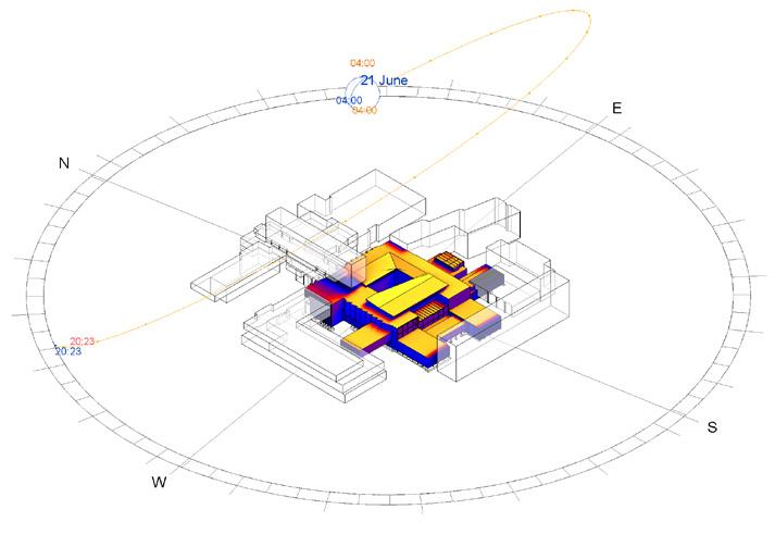
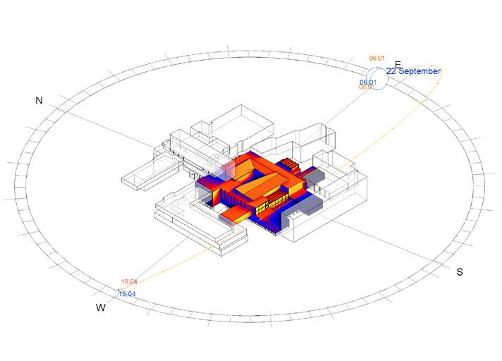
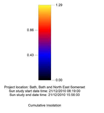

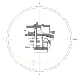
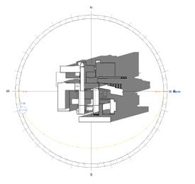
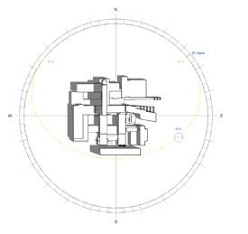
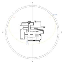
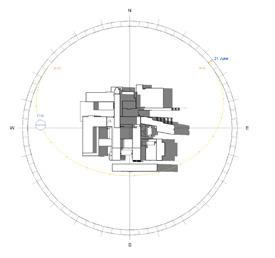
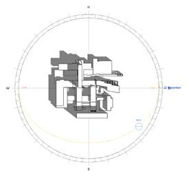
Cumulative insolation of building envelopes in different seasons
The project aims to simply calculate the building exterior, without taking into account the inside area layout. Nevertheless, the choice of partition wall material might also impact the building’s performance. To summarise, the issue of overly daylight, along with overheating, indicates that multiple factors such as daylight, ventilation, acoustics, and thermal comfort are connected. The design selection will vary based on the specific features of the area and the expected performance criteria for the project.
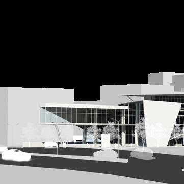
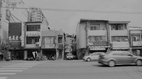
Taichung City, Taiwan
MIXED-USE CAR SHOWROOM
TYPE
INSTRUCTOR
Feb. 2017 - Jun. 2017
Year 4, Studio Pproject (Individual)
WenPin Huang Architect
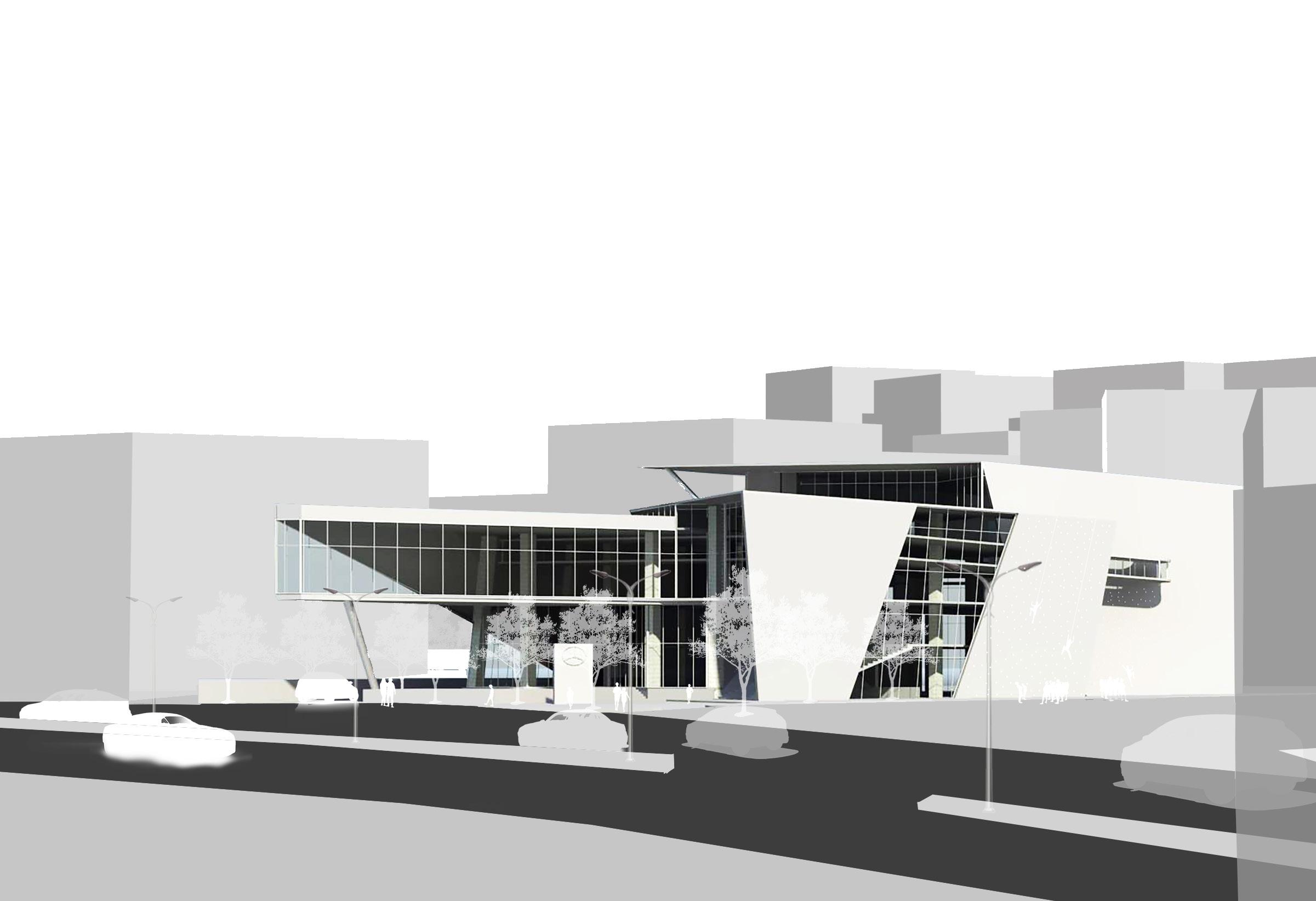
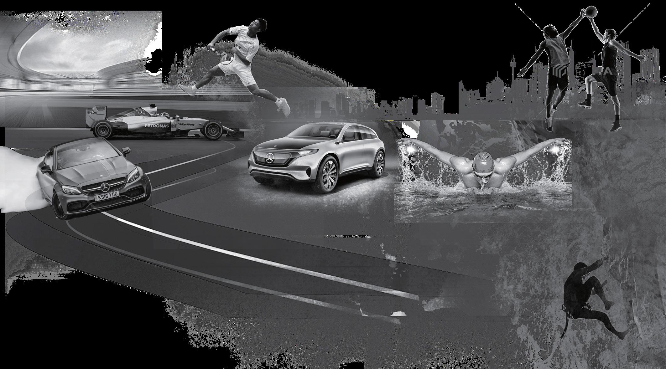
The project is a mix-used car showroom. Students was asked to define the car brand as well as the mix-used function based on the values and visions of the brand. The semester was divided into two parts, which the first part focus on the concept, case study and set the basic programme based on the Building Regulations and the second part focused on the detail drawings and constuction interfaces, and produced the final presentation with the architectural drawings and renderings. I was selected as one of the honor projects at the end of the semester.
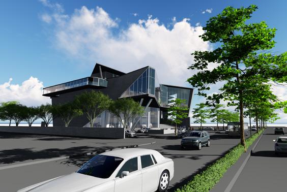
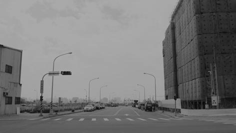
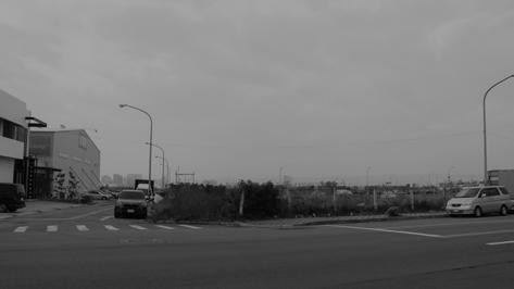
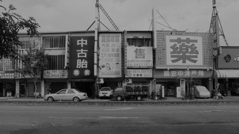
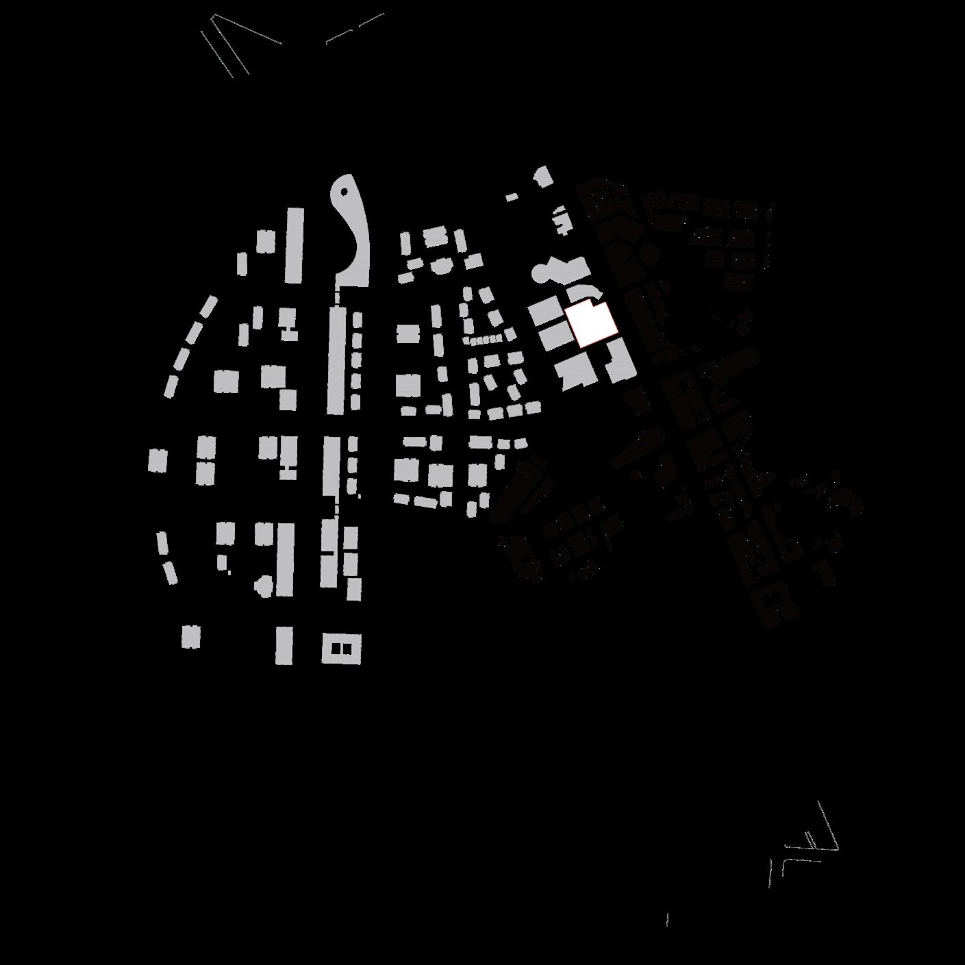
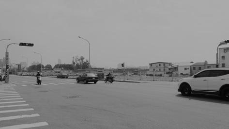
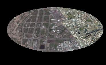
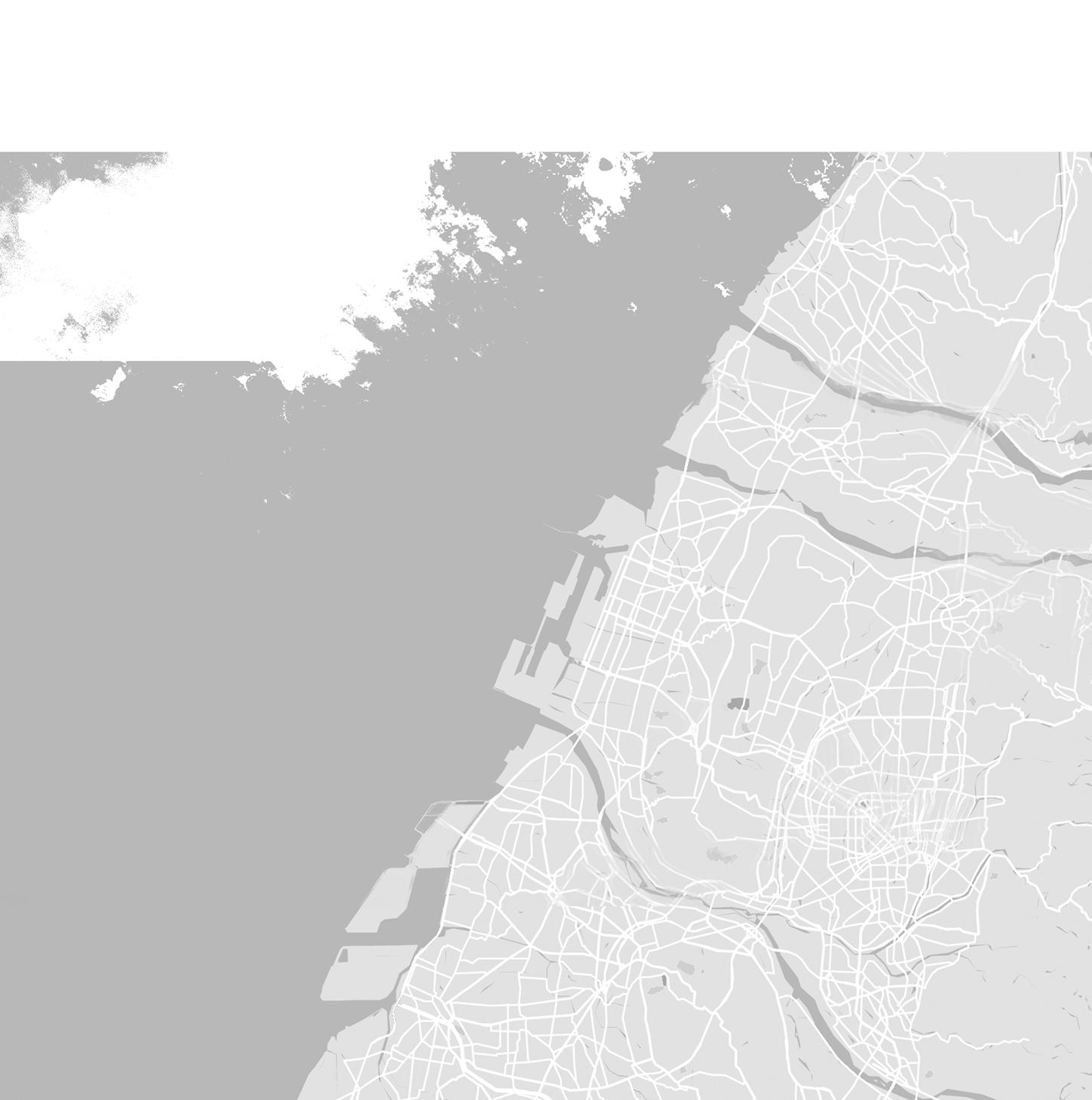
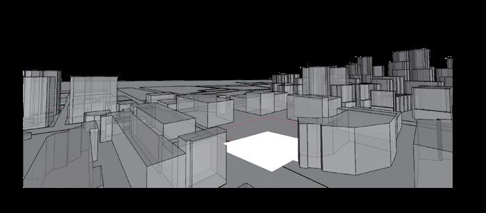
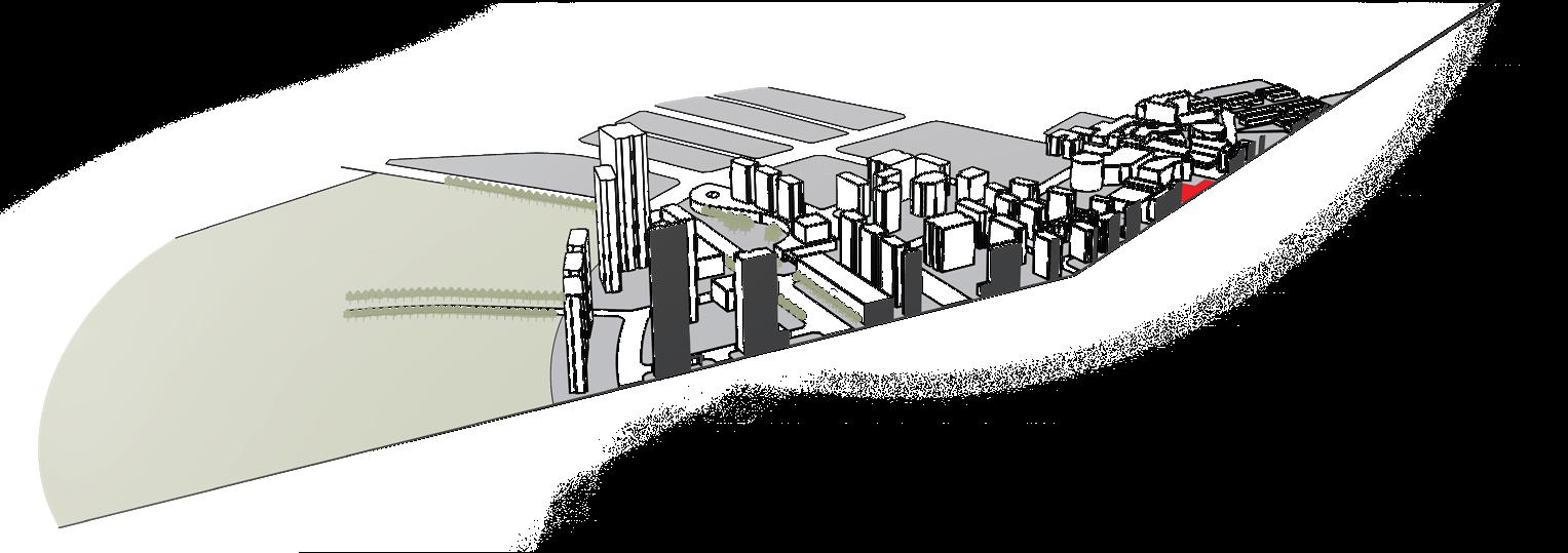
The site is located in the unit eight area of ‘‘Shuinan Economic and Trade Park’’ in Taichung City which is still under developement. Considering the huge change whthin 20 years due to the new development area, I model the future cityscape based on the land use control from the govenment.
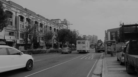
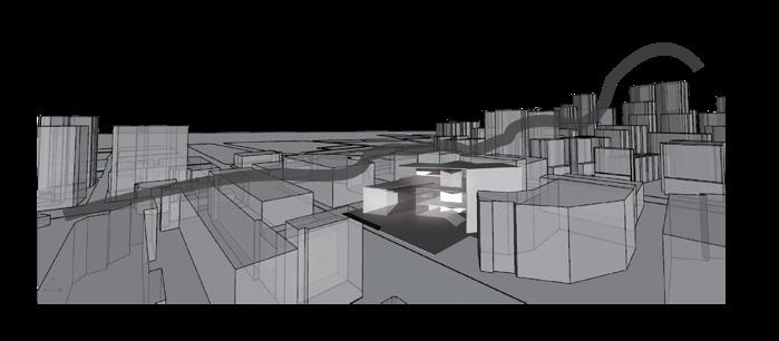
Due to the location in the middle of the new developement area and old town, being alone with the main street, the population growth in the area is expected. As the new area start the construction, the temporary sports facilities will be removed. To contain with all age groups meanwhile, I choose the Sport Center as the mixed-use program for the car showroom.

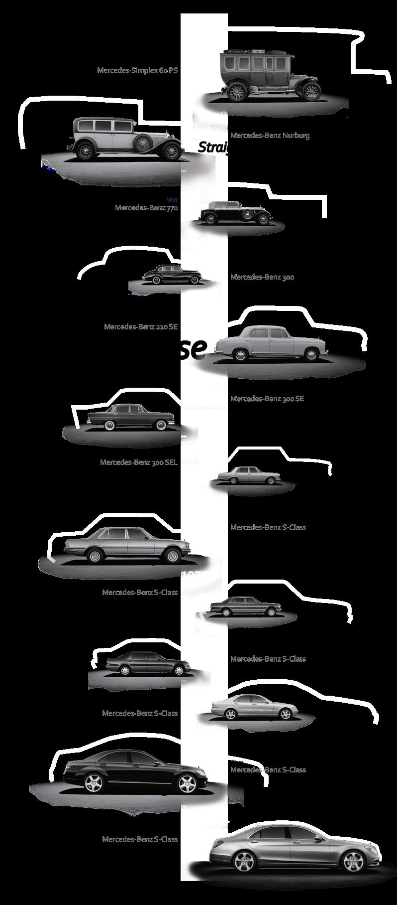
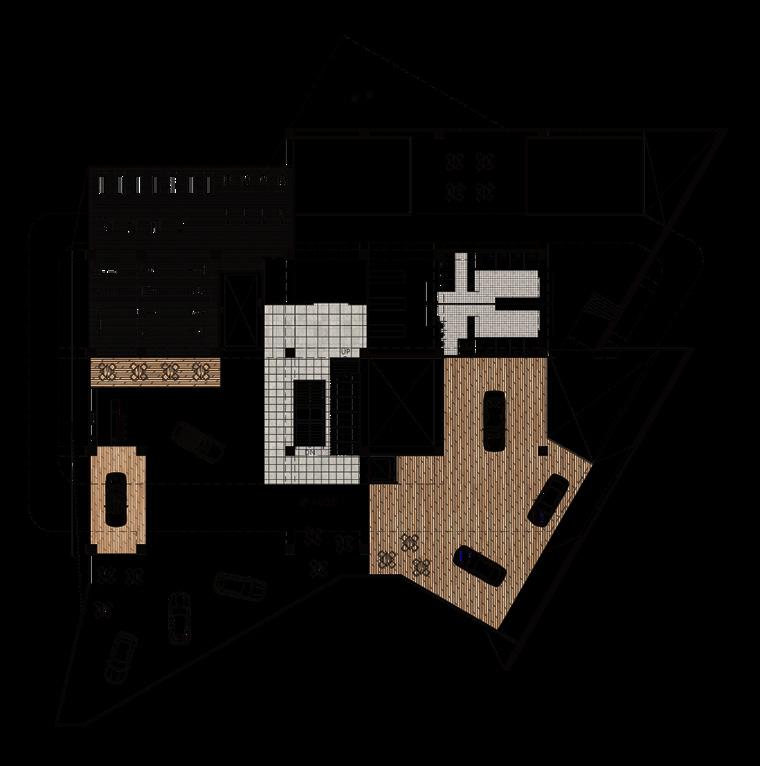
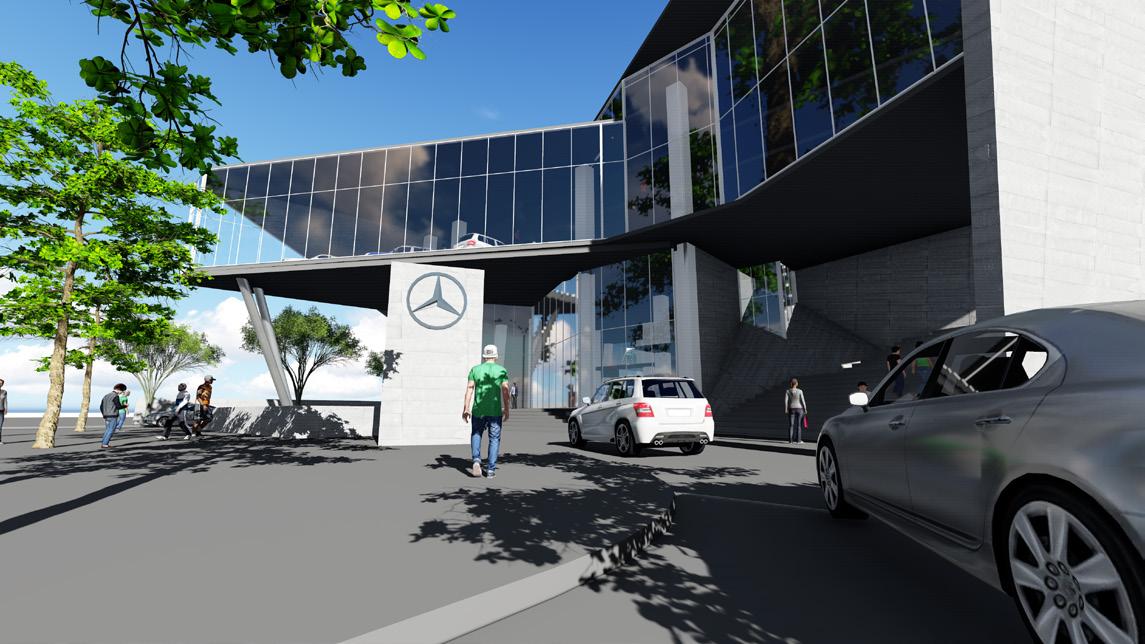
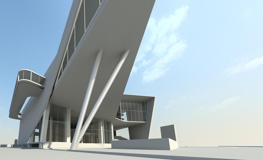
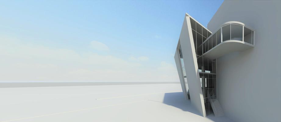
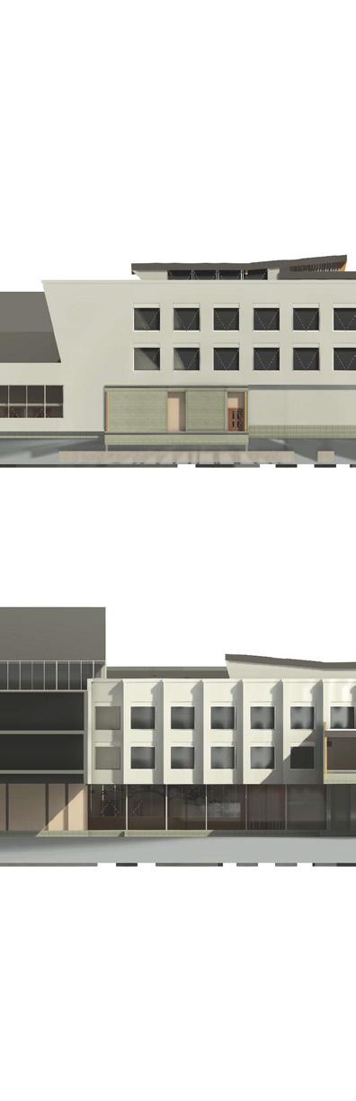
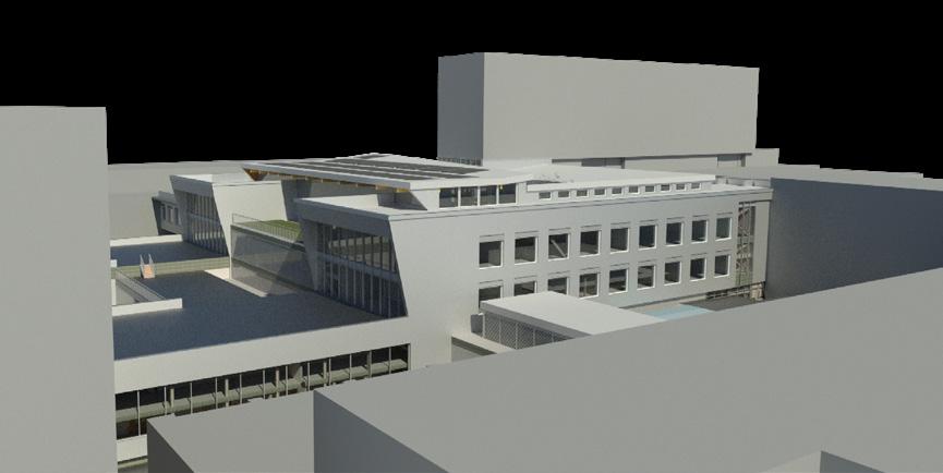
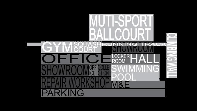
Sonderklasse, means special class in German, represent the value of the brand which can be traced back to the Simplex 60 in 1903. The highclass of the car is redefined as the language of the showroom space, while the sporty shape create the functionality of a sport center. Combinded with the city contour, the new mixed-use building will bring an international company into the city and bring out a new space for public in the meantime.


New car Display
EQ Display
AMG Display
S-class Display
Meeting area
Lounge
Collection area
Roof restaurant
Maintenance Works
Lifting platform x8
Hall
Locker room
Changing room
25 meter swimming pool
Spas
Gym
Squash court
Running track
Multi-sport ballcourt
Climbing wall
Office for Showroom
Office for Sport center
Pantry
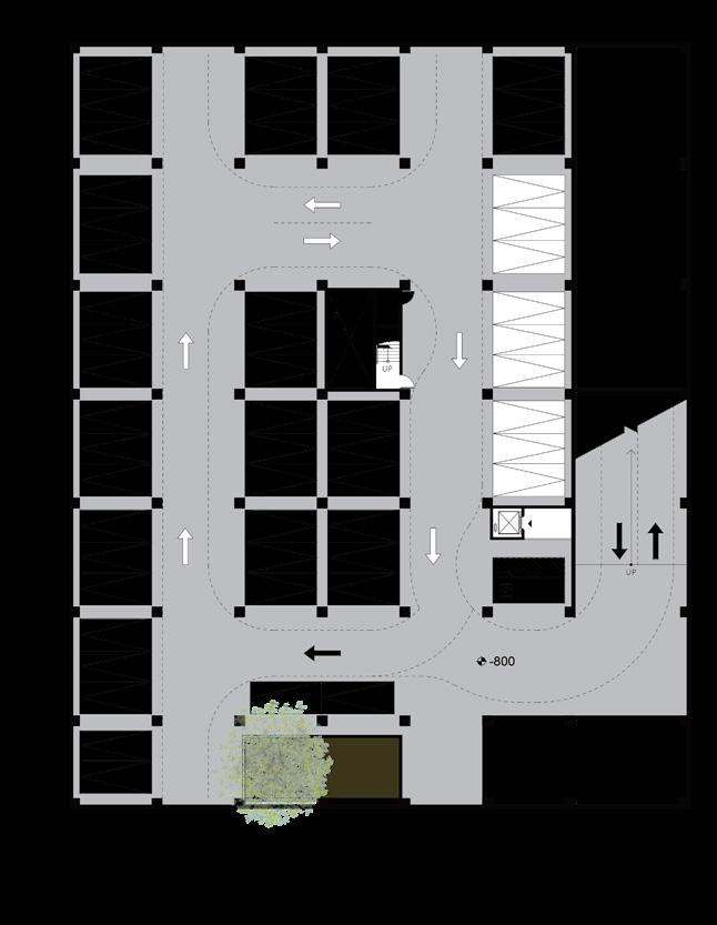
Scooter parking
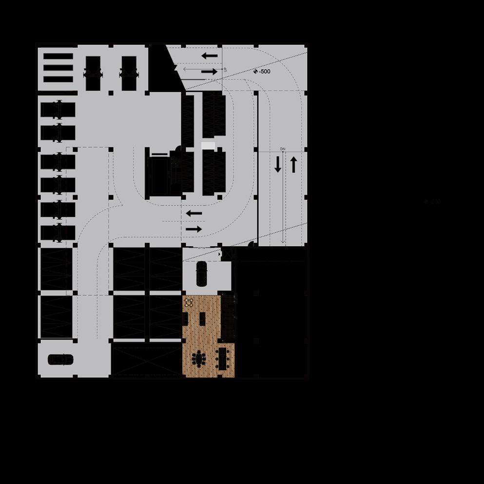
Customer car parking
Disabled parking
Staff parking
New car storage
Temporary parking
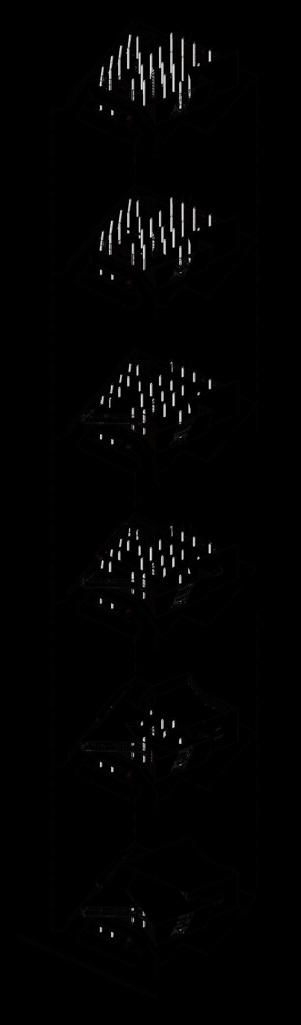
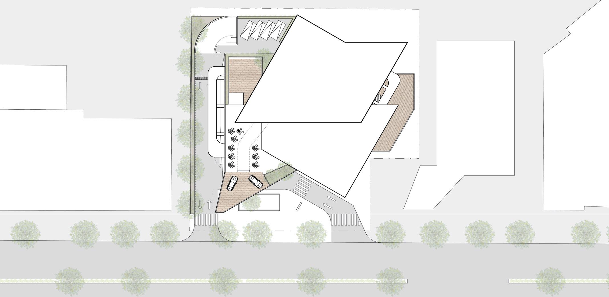


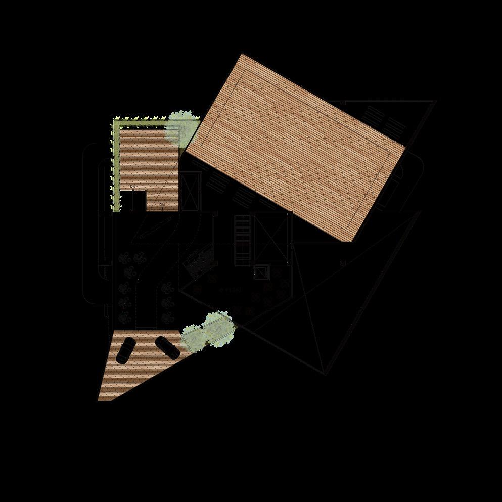
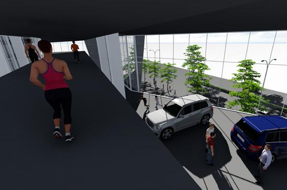
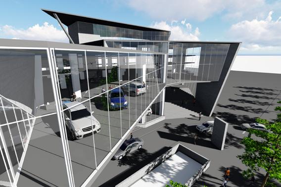
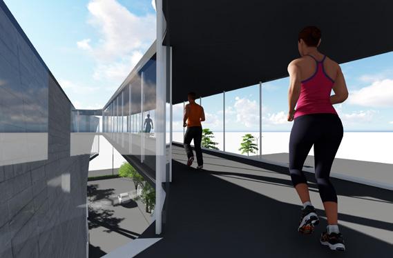
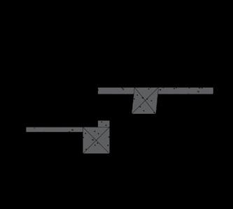
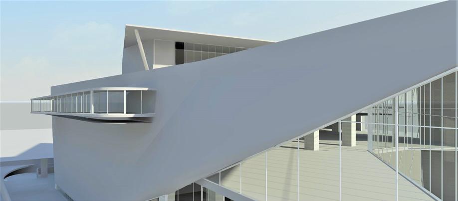
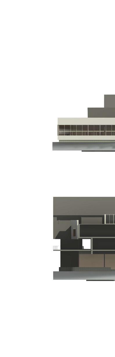
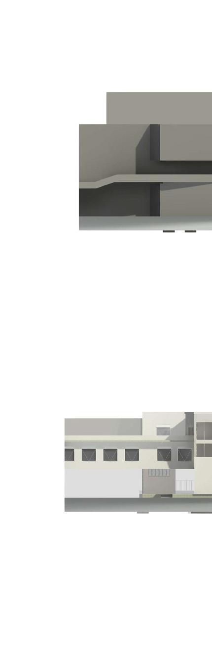
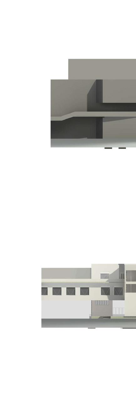
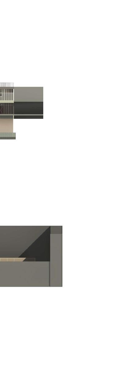
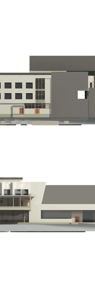
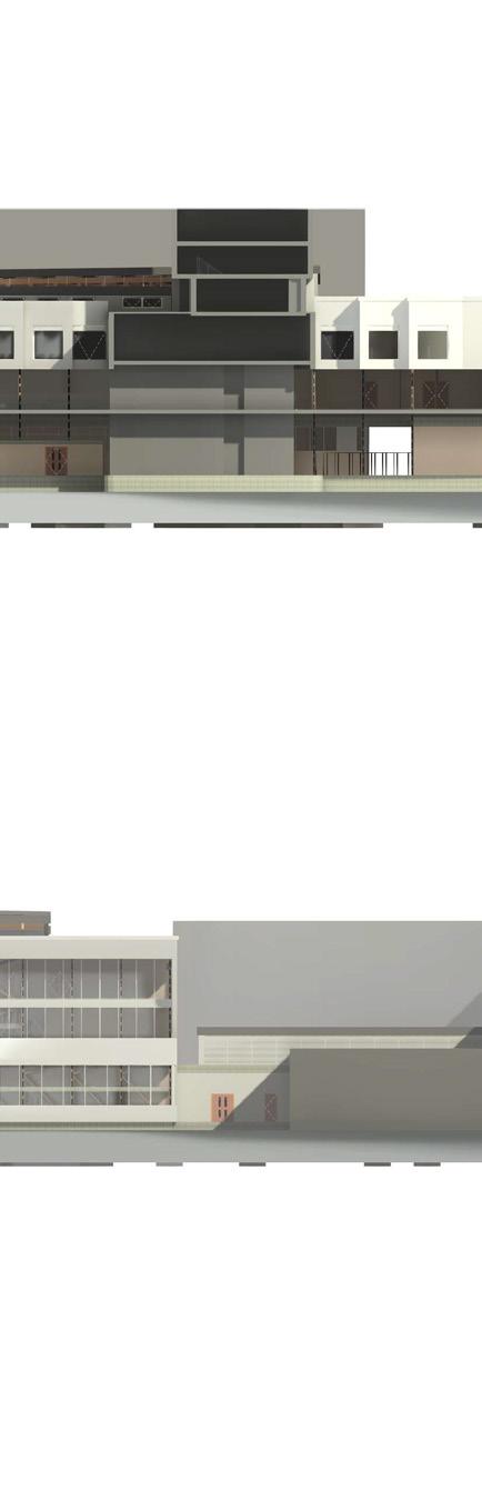
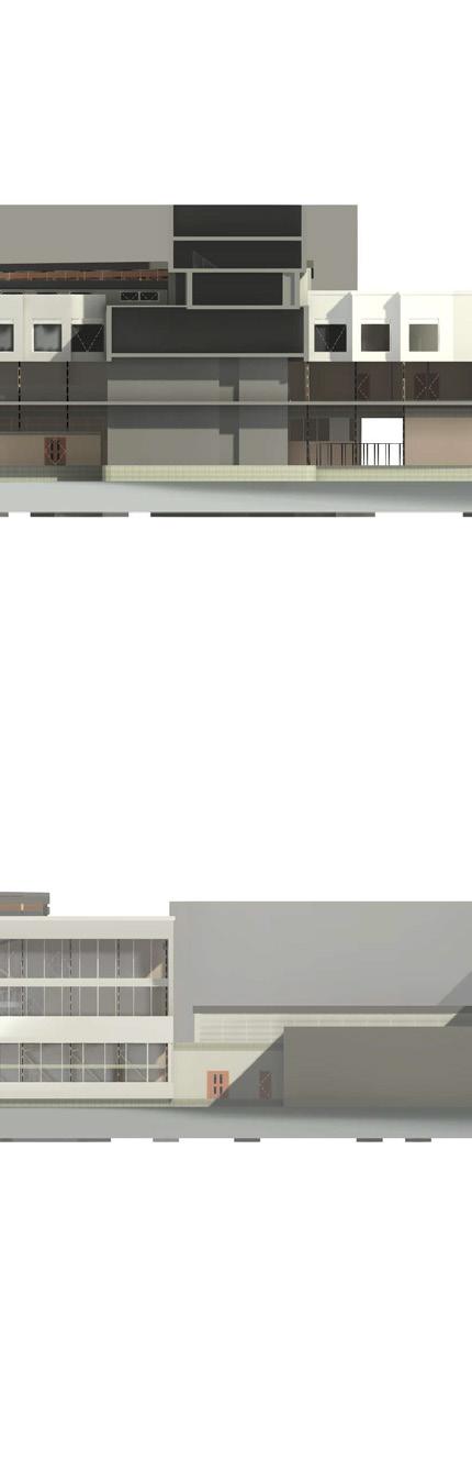
To display the car to people standing on the road, I create a cantilever structure toward the way of traffic flow for the display area,and it became the entrance of the showroom at the same time. By the split-level, the entrance of sport center is at second floor with a special stairs.
In another perspective, I tried to display not only car brand but also the sport center. People can run at the mezzanine floor from the top of the showroom to outdoor cantilever structure grew from the facade. I also create a slanted climbing wall at the West facade to enrich the dancity of the building.