PORTFOLIO
Kazuma Yoshimura | 2016 - 2024 | Architectural Technology
George Brown College | Ontario Advanced Diploma
Table of Contents
2 Portfolio (2016-2024)
George Brown College (Canada)
01_ Mazda Car Dealership
02_ Raft Swan House
03_ Warehouse Project
04_ The Hillcrest Community School Art Studio
05_ Wood Frame Model & Wall Section Detail
06_ Mix-used Commercial Building
Tokai University and Meiji University (Japan)
07_ Aguri Scape
08_ Sendagaya Delivery Junction
09_ A Brick Home that Nurtures Assets
10_ Sony Culture Box
3
_p.12 _p.06 _p.18 _p.24 _p.28 _p.32 _p.36 _p.42 _p.46 _p.48
Kazuma Yoshimura

April 2016 - March 2020
April 2020 - July 2020
Jan. 2023 - Present
Education Professional Experience
July 2017 - Sep. 2017
Dec. 2019 - Sep. 2020
Tokai University, Kanagawa, Japan
Bachelor of Architecture Engineering
GPA 3.88
Meiji University, Kanagawa, Japan
Master of Architectue and Urban Design (Only Summer Studio) Completed Studio1 Course Work
George Brown College, Toronto, Canada
Advanced Diploma of Architectural Technology
GPA 3.88
July 2020 - Sep. 2020
July 2023 - Present
MORIYA AND PARTNERS, Tokyo, Japan
Architecture Model Making Assistant
Nikken Sekkei, Tokyo, Japan
Urban Design Department
3D Modeling and Design Assistant
INA Institute of New Architecture, Tokyo, Japan
Building Design Department
Architecture Model Making Assistant
George Brown College, Toronto, Canada
Tutored 12 Students in CAD 01, CAD 02, Revit, Studio 01, Studio 02, and Visual Communication 01
4
First Place × 1
(Architecutural Design Studio 3 (Tokai Univ.))
First Place × 2
(Architecutural Design Studio 4 (Tokai Univ.))
First Place × 1
(Architecutural Design Studio 5 (Tokai Univ.))
First Place × 1
(Architecutural Design Studio 6 (Tokai Univ.))
Kajima Special Award (Tokai University × Kajima Corporation “Manufacturing Summit 2019”)
Honorable Mention with $500 (2nd Asahi Global Student Design Competition)
2nd Place
(Tokai University Graduation Design)
Jury’s Special Award (Tokai University Architecture Association Graduation Design Review)
Selected as one of Japan’s Top 85 (Akarenga Graduation Design in 2020)
Deans Honour Lists (1st Semester, 2023 Winter (George Brown College))
Deans Honour Lists (2nd Semester, 2023 Spring (George Brown College))
Deans Honour Lists (3rd Semester, 2023 Fall (George Brown College))
Deans Honour Lists (4th Semester, 2024 Winter (George Brown College))
Selected as a Student Example (Architectural Technology Studio 2, George Brown College)
5th Place (2024 Skills Ontario Competition, Architectural Technology & Design, the student representative at George Brown College)
Software
Illustrator, Photoshop, Indesign, Premiere Pro
Word, Excel, PowerPoint
AutoCAD, Revit, Sketchup, Rhinocerous, Grasshopper, Dynamo
Lumion, Twinmotion
5 Adobe Softs 2017 Microsoft Office Drawing & Modeling Rendering 2018 2019 2023 2024
Awards

Mazda Car Dealership
Program Course
Production Period
Location
Award
Member
_Automotive Dealership
_Architectural Technology Studio 4
_March 2024 - April 2024
_Vanghan (GM2 Zone), Ontario, Canada
_A+ Grade
_Litsa Trochatos
Software
Project Description

_Revit, Lumion, Photoshop, Indesign
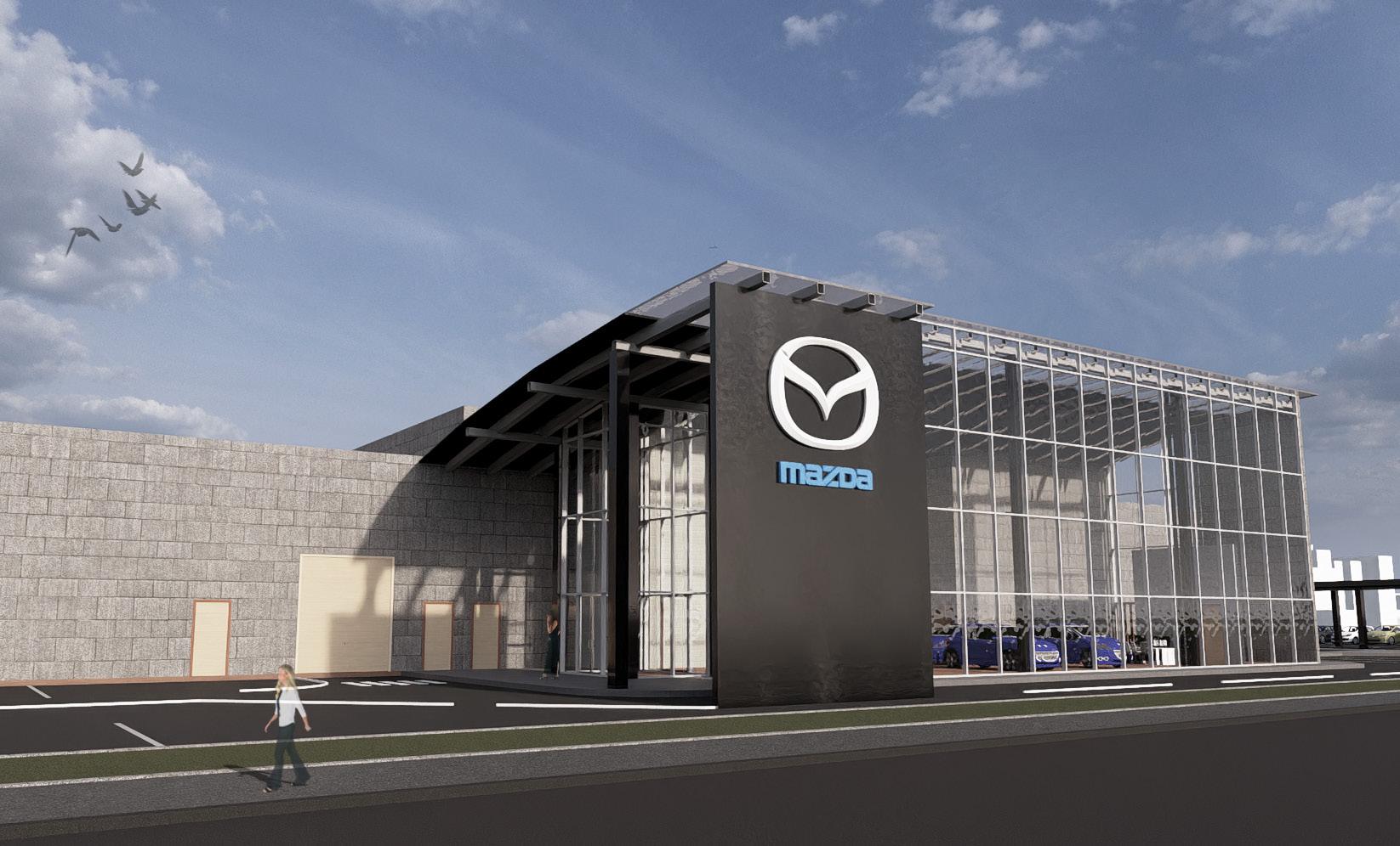
This project involves designing a car dealership with studio partner. The site already includes two existing buildings with repair garages. In accordance with Vaughan by-laws, it is crucial for students to consider how to enhance the car brand and design a layout that complies with building code requirements. Students have the freedom to select the car brand for their dealership design project.
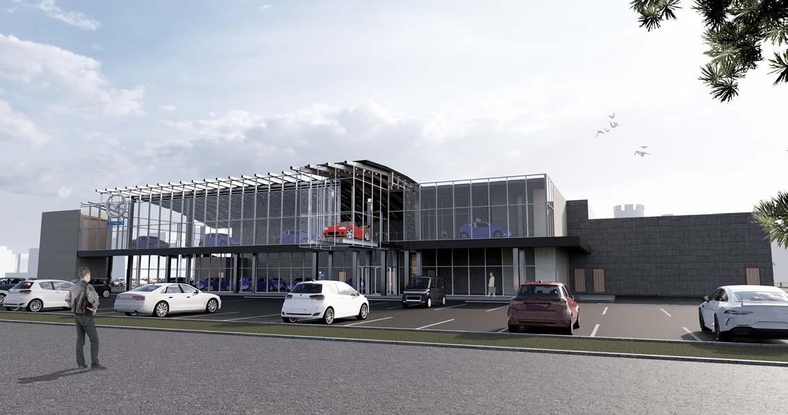
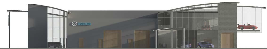
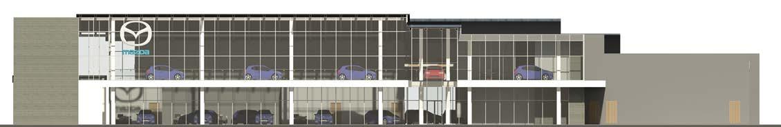
The Mazda dealership, designed to captivate, features an upper-floor car display visible from the street, highlighting Mazda’s racing heritage. The distinctive curved roof and glass box showcase a suspended race car, emphasizing innovation and speed. Inside, a modern showroom with luxurious furnishings presents Mazda’s latest models.
6 George Brown College (2023-2024)
01
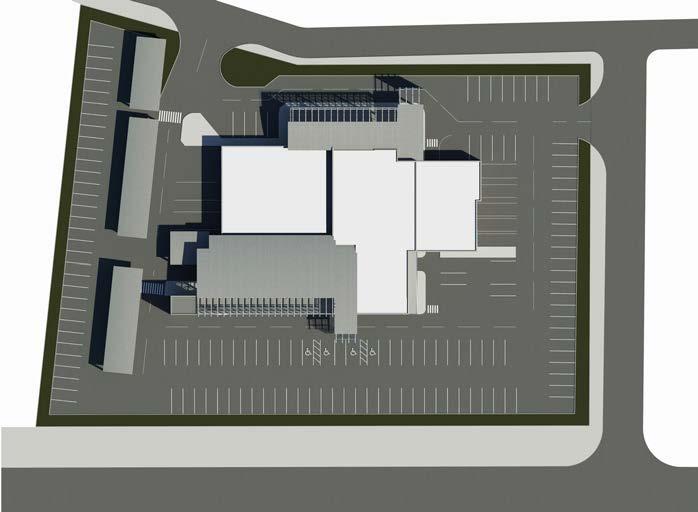
The exisiting buildings are located in the center of the site
The volumn and location of the new building
The slope of the roof adjusted to open towards each street side
DESIGN CONCEPT STATEMENT


7
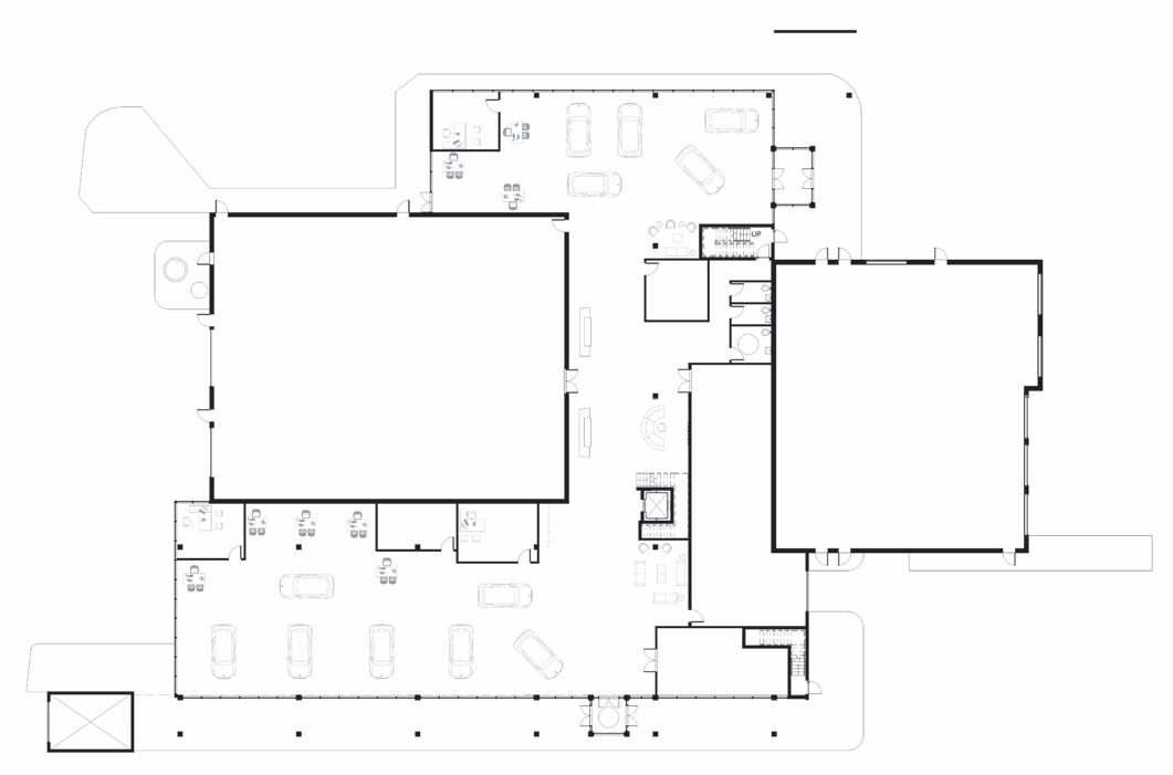
MATERIALS MAZDA CAR DEALERSHIP KENDAL AVENUE MACPHERSON AVENUE BRIDGMAN AVENUE EXISTING BUILDING EXISTING BUILDING EXISTING BUILDING EXISTING BUILDING 1 4 5 6 7 8 9 10 11 12 13 14 15 23 25 16 18 20 18 19 21 1 2 2 9 22 24 2 3 12 LEGEND 1. VESTIBULE 5. NEW VEHICLES WORK STATION 9. CUSTOMER LOUNGE 13. STAIRS AND ELEVATOR 2. COVERED WALKWAY 6. NEW VEHICLE SALES MANAGER OFFICE 10. PARTS ROOM 23. EXISTING - SERVICE DEPARTMENT 14. RECEPTION 18. STAFF WASHROOM 24. PRE-OWNED VEHICLE SALESPERSON WORK STATION 3. FREIGHT ELEVATOR 7. VIRTUAL REALITY ROOM 11. DEALER STORE 25. EXISTING - SERVICE FAST LANE 15. RETAIL SALES COUNTER 19. MULTIMEDIA ROOM 4. NEW VEHICLES WORK STATION 8. GENERAL MANAGER OFFICE 12. FIRE RATED EXIT 20. CUSTOMER BARRIER FREE UNIVERSAL WASHROOM 22. PRE-OWENED VEHICLE SALES MANAGER OFFICE 16. RETAIL PARTS COUNTER 21. PRE-OWNED VEHICLE SHOWROOM
SITE PLAN
FLOORING CURTAIN
POLISHED CONCRETE ALUMINUM METAL ROOF BRICK ALUMINUM COMPOSITE PANELS FIRST FLOOR PLAN N
VINYL
WALLS
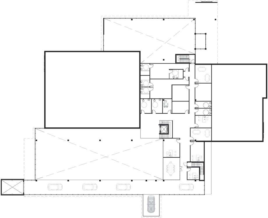
SECOND FLOOR PLAN
8 George Brown College (2023-2024) 1 2 3 4 5 6 OPEN TO BELOW EXISTING BUILDING EXISTING BUILDING OPEN TO BELOW 7 8 9 10 10 11 12 13 14 15 15 15 15 16 16 171818 19
6.
5.
10. STAFF BARRIER-FREE
14. CUSTODIAL/JANITORIAL STORAGE
2.
ELEVATOR 7.
OFFICE AREA 11. MISCELLANEOUS STORAGE 16. BARRIER-FREE LOCKER ROOM 15. BARRIER-FREE
AND SHOWER 3.
8.
12.
17.
9.
13. FIRST AID
18. CUSTOMER BARRIER-FREE WASHROOM 19. FREIGHT ELEVATOR LEGEND
1. FIRE RATED STAIRS
DEALER OFFICE
SPARE OFFICE
WASHROOM
ROOM
STAIRS AND
GENERAL
WASHROOM
NEW VEHICLE DISPLAY AREA
SALES AND ADMIN STAFF LUNCHROOM
LUNCH ROOM
SECURITY 4. CONFERENCE ROOM
CONTROLLER OFFICE
ROOM
NORTH ELEVATION WEST ELEVATION N
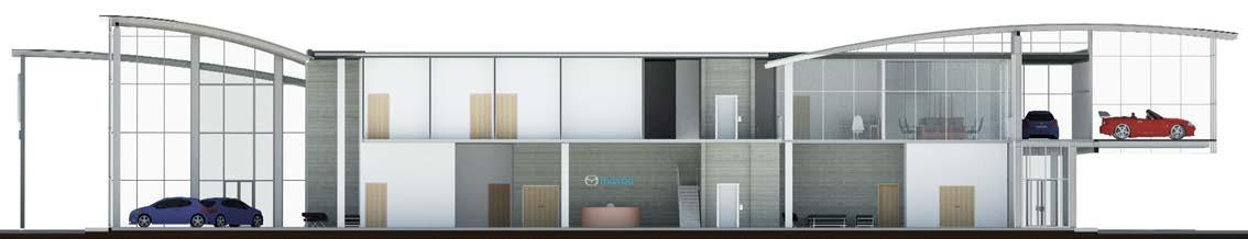
EAST - WEST CROSS SECTION
GLAZED ROOF
ALUMINUM METAL ROOF
HSS RECTANGULAR JOISTS

EPDM RUBBER FLAT ROOF

HSS RECTANGULAR BEAM


H-SHAPE COLUMN
CURTAIN WALLS

910mm REINFORCED CONCRETE CAISSON FOUNDATION
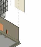
300mm POURED CONCRETE TRENCH WALL
900 x 300mm BEARING FOOTING
203mm CONCRETE BLOCK

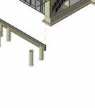

9
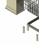
STRUCTURAL ISOMETRIC VIEW
PRE-OWNED VEHICLE SHOWROOM RECEPTION CUSTOMER LOUNGE BARRIER-FREE WASHROOM AND SHOWER CUSTOMER BARRIER-FREE WASHROOM NEW VEHICLE DISPLAY AREA CUSTOMER
LOUNGE
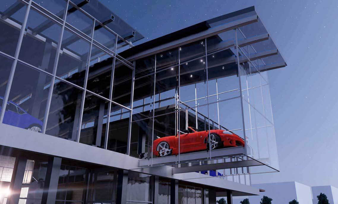
SUSPENDED CAR DISPLAY
10
Brown College (2023-2024)
George
EXTERIOR
EAST VIEW
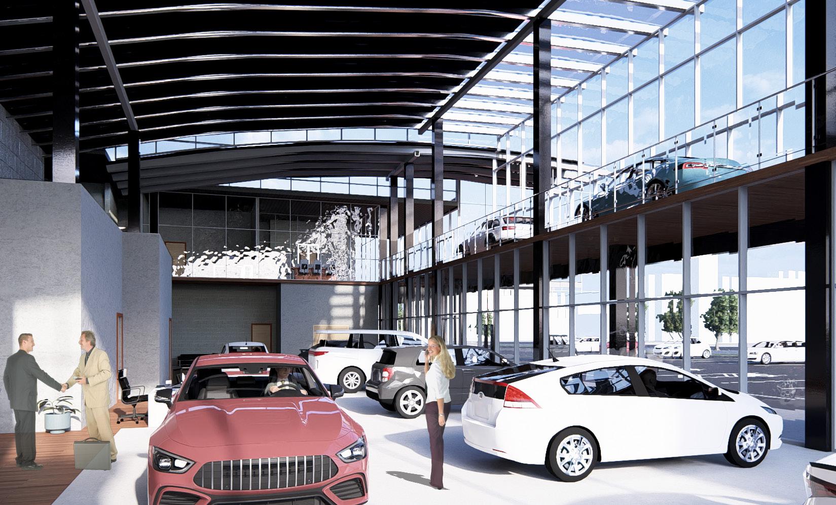
NEW VEHICLE SALES AREA
11
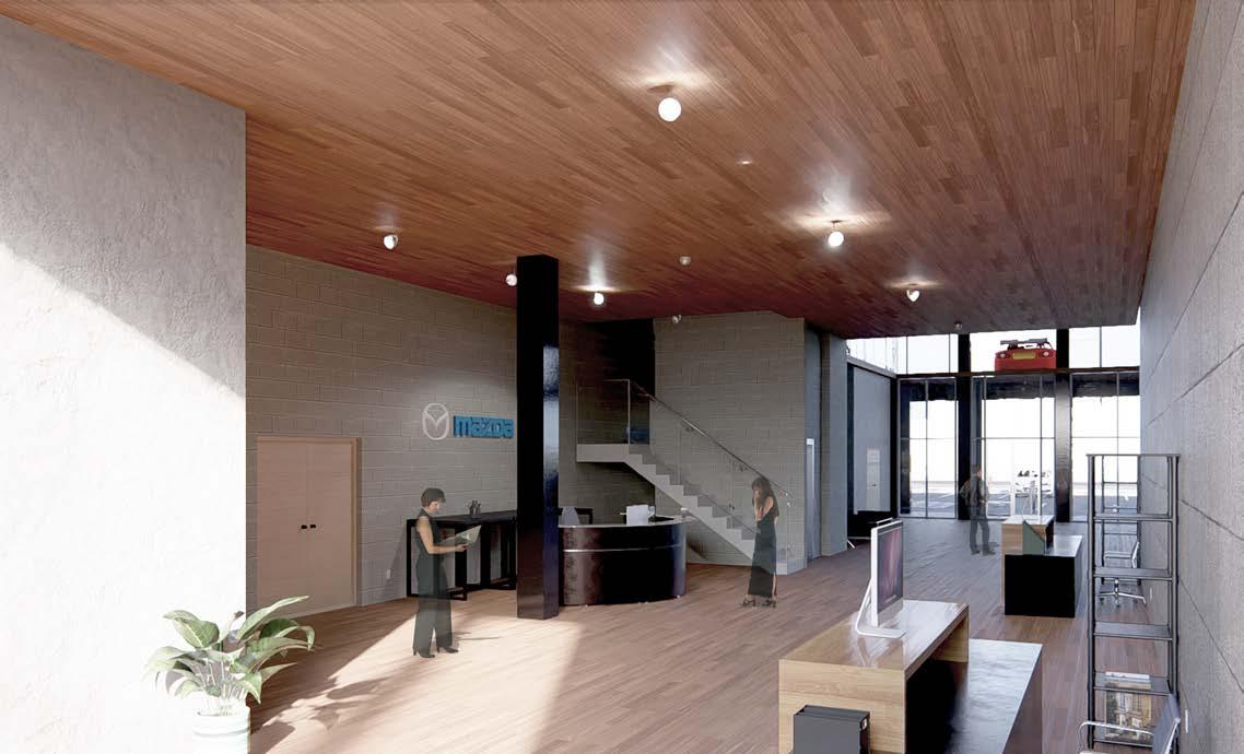
RECEPTION AREA
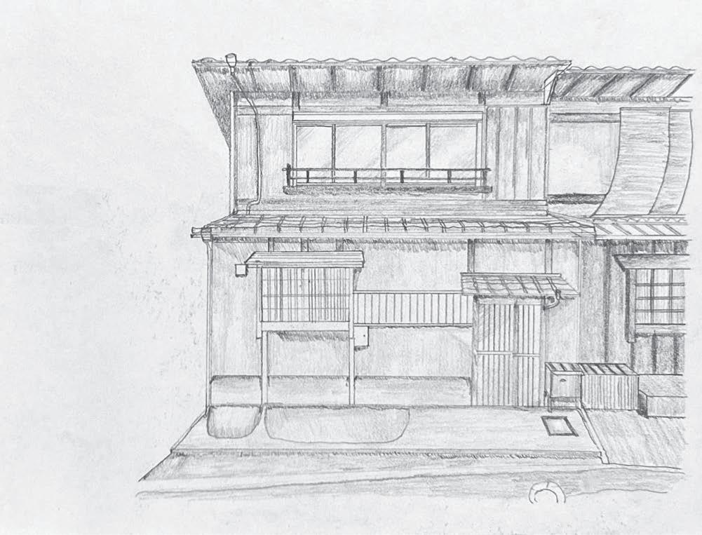
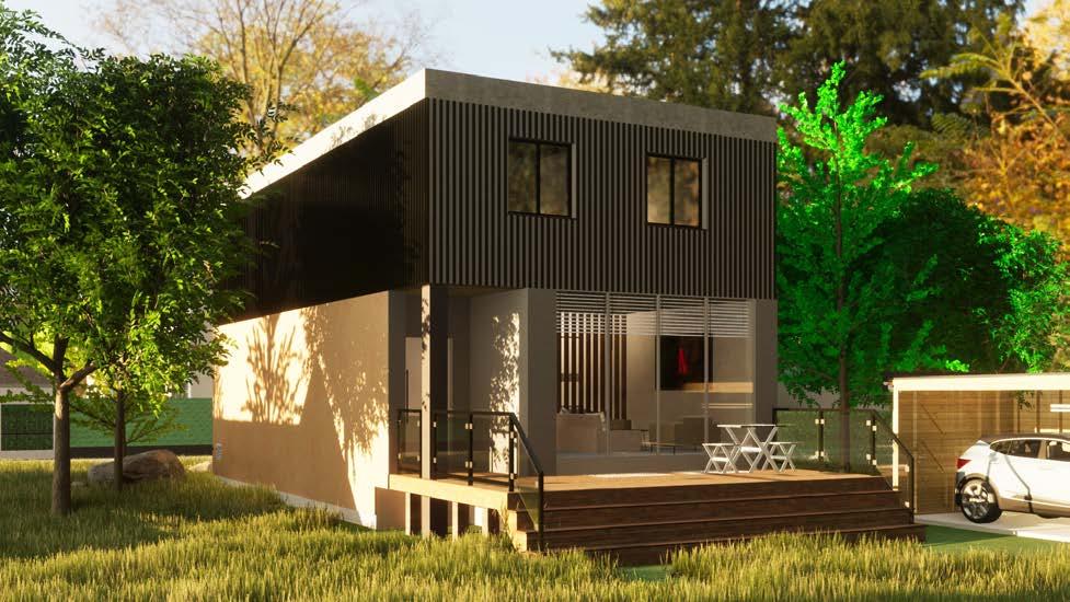
Raft Sawn House
Program Course Location
Production Period Award
Member
_2 Storey House
_Architectural Technology Studio 2
_May 2023 - August 2023
_N/A
_Selected as a Student Example
_Eunice Leung

Project Description
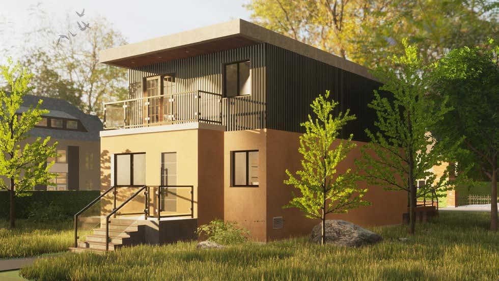
This is the project where the group of two is required to design a 2-storey house. The processes for this project can range from researching the Ontario Building Code to generating the construction detail drawings throughout the semester. Furthermore, each student must choose the suitable materials and structural elements learned from correlated classes; then apply them to the project.
12 George Brown College (2023-2024)
02
Front View
Rear View
_AutoCAD,
Twinmotion, SketchUp
Software
SUSTAINABLE MATERIALS
WOOD FRAME
“NADURA” INSULATED CONCRETE FRAME
ROOF
“AMERICAN WEATHERSTAR” SPRAY POLYURETHANE FOAM
EXTERIOR
“GENTEK” RECYCLED ALUMINUM SIDING
“CANADIAN STUCCO” Family Room


PRIMARY BEDROOM, ENSUITE, BATHROOM, LAUNDRY, BEDROOM 1, BEDROOM 2 2ND FLOOR


LIVING ROOM, DINING ROOM, POWDER ROOM, KITCHEN, FAMILY ROOM, DECK 1ST FLOOR


BASEMENT
GUEST BEDROOM, BATHROOM, RECREATONROOM, LAUNDRY, MEDIAROOM, MECHANICAL ROOM

13 AXONOMETRIC VIEW
N NO. DRAWN BY CHECKED BY DATE SHEET TITLE PROJECT NAME SCALE THE CONTRACTOR RESPONSIBILITY CONDITIONS ARCHITECT SUPPLIED INFORMATION. RESPONSIBLE SURVEY, STRUCTURAL, ENGINEERING DRAWINGS. DRAWINGS WORK. CONSTRUCTION APPLICABLE AUTHORITIES. SCALED. GRAPHIC REPRESENTATIONS SHEET NO. PROJECT ADDRESS RIFTSAWN A02 512 JONES
SITE PLAN
14 George Brown College (2023-2024)
FIRST FLOOR PLAN N N ..\WEEK 7_GOOGLE_DRIVE\RIFTSAWN_LOGO.jpg REVISION NO. DESCRIPTION DRAWN BY CHECKED BY DATE SHEET TITLE PROJECT NAME SCALE THE CONTRACTOR RESPONSIBILITY FOR CONDITIONS ON SITE ARCHITECT OF ANY SUPPLIED INFORMATION. RESPONSIBLE FOR SURVEY, STRUCTURAL, ENGINEERING INFORMATION DRAWINGS. REFER DRAWINGS BEFORE WORK. CONSTRUCTION APPLICABLE CODES AUTHORITIES. DRAWING SCALED. ARCHITECTURAL GRAPHIC REPRESENTATIONS SHEET NO. PROJECT ADDRESS RIFTSAWNDESIGNSTUDIO.CA E. K.YOSHIMURA 2023-06-23 BASEMENT RIFTSAWN A03 512 JONES N ..\WEEK 7_GOOGLE_DRIVE\RIFTSAWN_LOGO.jpg REVISION NO.DESCRIPTION DRAWN BY CHECKED BY DATE SHEET TITLE PROJECT NAME SCALE THE CONTRACTOR RESPONSIBILITY FOR CONDITIONS ON SITE ARCHITECT OF ANY SUPPLIED INFORMATION. RESPONSIBLE FOR SURVEY, STRUCTURAL, ENGINEERING INFORMATION DRAWINGS. REFER DRAWINGS BEFORE WORK. CONSTRUCTION APPLICABLE CODES AUTHORITIES. DRAWING SCALED. ARCHITECTURAL GRAPHIC REPRESENTATIONS SHEET NO. PROJECT ADDRESS RIFTSAWNDESIGNSTUDIO.CA E. K.YOSHIMURA 2023-06-23 FIRST FLOOR RIFTSAWN A04 512 JONES N
BASEMENT FLOOR PLAN
SECOND FLOOR PLAN
15
N
REAR ELEVATION NO. DRAWN BY CHECKED BY DATE SHEET TITLE PROJECT NAME SCALE THE CONTRACTOR RESPONSIBILITY CONDITIONS ARCHITECT SUPPLIED RESPONSIBLE SURVEY, ENGINEERING DRAWINGS. DRAWINGS WORK. CONSTRUCTION APPLICABLE AUTHORITIES. SCALED. GRAPHIC SHEET NO. PROJECT ADDRESS SECOND A05 512 N REVISION NO. DESCRIPTION DATE CHECKED BY DATE SHEET TITLE PROJECT NAME SCALE THE CONTRACTOR MUST VERIFY AND ACCEPT RESPONSIBILITY FOR ALL DIMENSIONS AND CONDITIONS ON SITE AND MUST NOTIFY THE ARCHITECT OF ANY VARIATIONS FROM THE SUPPLIED INFORMATION. ARCHITECT IS NOT RESPONSIBLE FOR THE ACCURACY OF THE SURVEY, STRUCTURAL, MECHANICAL, ETC., ENGINEERING INFORMATION SHOWN ON THESE DRAWINGS. REFER TO THE ENGINEERING DRAWINGS BEFORE PROCEEDING WITH THE WORK. CONSTRUCTION MUST CONFORM TO ALL APPLICABLE CODES AND REQUIREMENTS OF AUTHORITIES. DRAWING ARE NOT TO BE SCALED. ARCHITECTURAL SYMBOLS ARE GRAPHIC REPRESENTATIONS ONLY. SHEET NO. PROJECT ADDRESS 160 KENDAL AVE TORONTO, ON M5R 1M3 (416)416-2000 RIFTSAWNDESIGNSTUDIO.CA OF 17 E. LEUNG K.YOSHIMURA 1:75 2023-06-23 FRONT ELEVATION RIFTSAWN HOUSE A07 512 JONES ST, TORONTO ON
FRONT ELEVATION
16 George Brown College (2023-2024) RIGHT ELEVATION LONGITUDENAL SECTION
REVISION NO. DESCRIPTION DRAWN BY CHECKED BY DATE SHEET TITLE PROJECT NAME SCALE THE CONTRACTOR RESPONSIBILITY FOR CONDITIONS ON SITE ARCHITECT OF ANY SUPPLIED INFORMATION. RESPONSIBLE FOR SURVEY, STRUCTURAL, ENGINEERING INFORMATION DRAWINGS. REFER DRAWINGS BEFORE WORK. CONSTRUCTION APPLICABLE CODES AUTHORITIES. DRAWING SCALED. ARCHITECTURAL GRAPHIC REPRESENTATIONS SHEET NO. PROJECT ADDRESS E. K.YOSHIMURA 2023-06-23 LEFT RIFTSAWN A09 512 JONES NO. CHECKED BY DATE SHEET TITLE PROJECT NAME SCALE THE CONTRACTOR RESPONSIBILITY CONDITIONS ARCHITECT SUPPLIED RESPONSIBLE SURVEY, STRUCTURAL, ENGINEERING DRAWINGS. DRAWINGS WORK. CONSTRUCTION APPLICABLE AUTHORITIES. SCALED. GRAPHIC REPRESENTATIONS SHEET NO. PROJECT ADDRESS RIFTSAWN A10 512 JONES ..\WEEK 7_GOOGLE_DRIVE\RIFTSAWN_LOGO.jpg REVISION NO. DESCRIPTION DRAWN BY CHECKED BY DATE SHEET TITLE PROJECT NAME SCALE THE CONTRACTOR RESPONSIBILITY CONDITIONS ON ARCHITECT OF SUPPLIED INFORMATION. RESPONSIBLE FOR SURVEY, STRUCTURAL, ENGINEERING INFORMATION DRAWINGS. REFER DRAWINGS BEFORE WORK. CONSTRUCTION APPLICABLE CODES AUTHORITIES. DRAWING SCALED. ARCHITECTURAL GRAPHIC REPRESENTATIONS SHEET NO. PROJECT ADDRESS K.YOSHIMURA LONGITUDINAL RIFTSAWN A12 512 JONES
LEFT ELEVATION
17 WALL SECTION DETAIL
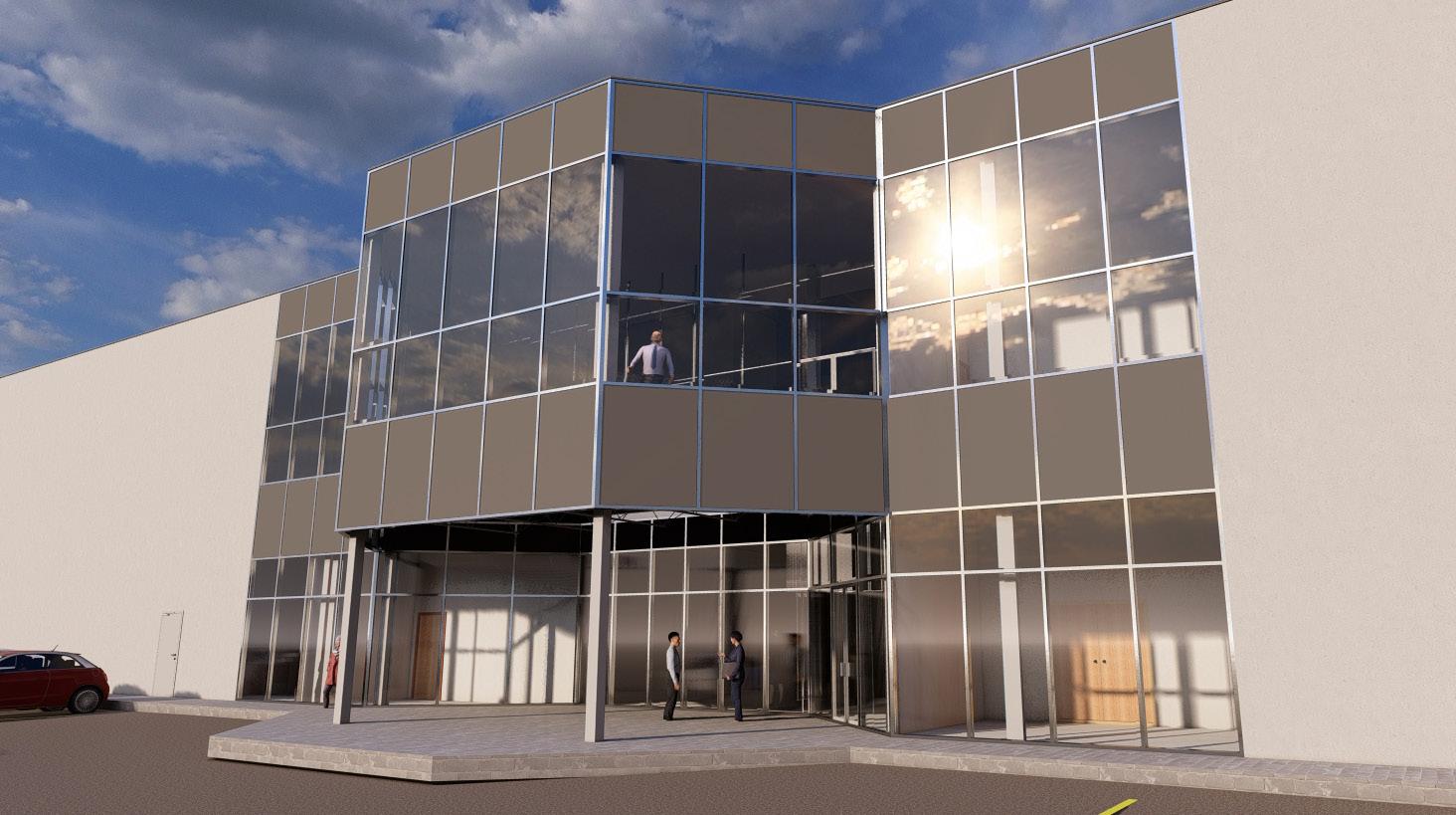
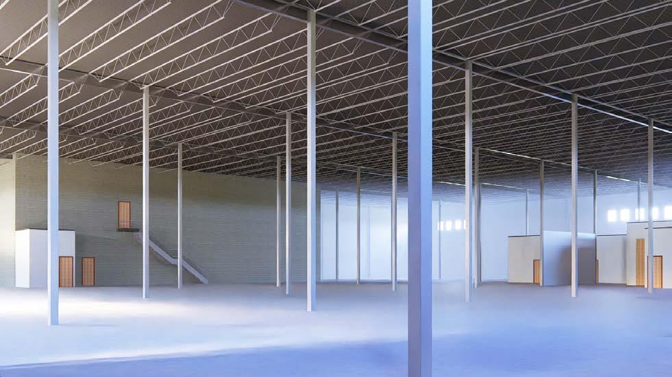
Warehouse Project
Program Course Location
Software
_Autodesk Revit, Lumion Production Period Award
_Warehouse for Distribution
_Architectural Technology Studio 4
_January 2024 - February 2024
_ Vanghan (EM2 Zone), Ontario, Canada
_A+ Grade
_Litsa Trochatos
Project Description:
This is a warehouse project for a group of two, located in the City of Vaughan. Firstly, students need to review the Vaughan zoning by-law to determine the maximum or minimum requirements. The warehouse must incorporate three different types of curtain walls, and students are required to understand their connections and composite materials. This project must be completed using Autodesk Revit only.
18 George Brown College (2023-2024)
Member
03
Office Entrance
Warehouse Area


19
PLAN
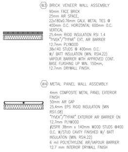
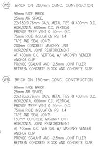
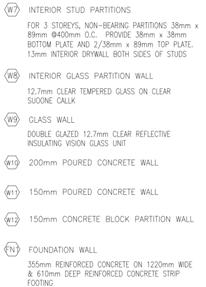
LEGEND FOUNDATION PLAN LEGEND CAR PARKING AND DRIVEWAYS HEAVY DUTY ASPHALT FIRE ROUTES AND TRUCKING SNOW STORAGE PROPOSED WAREHOUSE AREA = 4916.84 m 2 LANDSCAPE AREA NORTH STREET BLOCK A DRIVEWAY DRIVEWAY 13.84 82.30 3.40 2.70 5.70 5.70 LANDSCAPE AREA 2.70 DRIVEWAY RAMP UP RETAINING WALL WITH GUARD RAIL R15.00MR12.00MR9.00M R9.00M 112.18 m 7.60 3.00 3.00 6.20 5.70 2.70 3 8 8 3 12 12 3.00 1.50 24.50 34.34 14.27 17.47 30.29 22.66 11.99 8.14 10.27 SNOW STORAGE AREA PROPERTY LINE S 73° 09' 00" W PROPERTY LINE N 73° 09' 00" E PROPERTY LINE S 16° 51' 00" E 112.18 m 95.00 m 1.50 1.50 SNOW STORAGE AREA 5% OF ASPHALT LANDSCAPE 5% OF SITE AREA 0.05 X 10,657.10m² BARRIER FREE PARKING 4% OF PARKING PARKING 0.5 PER 100m² OF GFA 0.5 X (4,974.54/100) LOT COVERAGE FOOTPRINT / SITE AREA CALCULATIONS SNOW STORAGE 220.38m² 254.19m² LANDSCAPE 532.86m² 1045.81m² SOUTH (REAR) SETBACK 12m 12m WEST (INTERIOR) SETBACK 6m 13.84m EAST (INTERIOR) SETBACK 6m 16.05m NORTH (FRONT) SETBACK 6m 17.47m 1 : 300 A-2.0 SITE PLAN BLOCK B 1 1 A 11 2 3 4 5 6 9 10 F.1 2.1 8.1 5.1 6.2 5.2 6.1 A.1 8 F B C D E E.1 A-5.0 1 A-7.0 A-5.1 A-7.1 2 A-7.0 2 A-7.1 65.54 5.06 5.61 6.32 11.94 11.94 11.94 8.89 3.05 0.40 34.97 3.235.893.23 8.15 8.15 8.15 8.15 8.15 16.30 8.15 8.15 8.15 65.54 0.40 0.40 8.15 2.525.63 8.15 8.15 8.15 16.30 6.161.99 8.15 8.15 TYP. 910mm DIA. REINFORCED CONCRETE CAISSON FOUNDATIONS TYP. 300mm POURED CONCRETE TRENCH WALL 5.3 6.3 6.4 7 5.4 TYP. 203mm CONCRETE BLOCK W/ 2"x6" METAL STUD FRAMING 203mm CONCRETE BLOCK TYP. 900mm 300mm BEARING FOOTING A.0 34.98 82.31 1.97 3.232.942.943.231.97 0.40 10.67 82.31 10.68 54.86 2.83 0.40 0.41 0.41 225mm CONCRETE BLOCK RETAINING WALL 53.32 18.32 18.31 47.22 203mm CONCRETE BLOCK SUPPORTED SIZES & SPECIFICATIONS AS PER MANUFACTURER BETWEEN CONCRETE PANELS SIZES AS PER MANUFACTURER SIDING, 25mm AIR SPACE, AIR BARRIER, 60mm RIGID INSULATION, 38mm 150mm METAL STUDS, R-24 BATT INSULATION, 6mil VAPOUR BARRIER, 12mm GYPSUM BOARD ACOUSTIC INSULATION, 15.9mm TYPE GYPSUM BOARD @BOTH SIDES MANUFACTURER REINFORCED CONCRETE SLAB: ARCHITECTURAL TECHNOLOGY & STUDIO 4 ARCH 2005 JUSTIN J. HORVATH A-3.0 FOUNDATION PLAN PROJECT 1 GBC 1 : 200 A-3.0 FOUNDATION PLAN 1 N UP 6.2 8 6.4 7 2.98 2.54 3.05 3.22 1.35 1.20 3.45 1.50 1.45 5.58 2.49 4.77 3.07 3.31 1.20 1.50 2.88 3.70 8.89 3.05 3.23 2.35 3.23 1.97 8.15 1.30 3.22 4.84 2.82 1.01 12.39 3.10 9.29 W1 W2 W1 W1 W2 W5 W4 W5 W5 W4 W6 W6 W6 W6 W6 W6 W6 W6 W6 W6 W6 W6 W6 W6 W6 W6 W6 W6 W6 W6 F1 F1 m² SUPPLIES STORAGE & PHOTOCOPIER 10 m² PRIVATE OFFICE 12 m² PRIVATE OFFICE 14 m² SHARED OFFICE FOR PURCHASING 10 m² PRIVATE OFFICE 5 m² COMPUTER/SERVER & EQUIPMENT 4 m² W.C. 4 m² W.C. 10 m² UNIVERSAL BARRIER-FREE W.C. 11 m² KITCHENETTE 1.32 1.84 0.13 REINFORCED CONCRETE SLAB:220mm REINFORCED CONCRETE SLAB ON 6 MIL. POLYETHYLENE ON 150mm GRAVEL ON UNDISTURBED SOIL STEEL COMPOSITE DECK SLAB: 210mm CAST CONCRETE ON METAL DECK FLOOR TYPE F1 F2 GLAZED CURTAIN WALL: 200mm DEEP PRE-FINISHED ALUMINUM FRAME SUPPORTED SIZES & SPECIFICATIONS AS PER MANUFACTURER CONCRETE CURTAIN WALL: PRECAST CONCRETE PANEL CURTAIN WALL, 200mm THICK 'SANDWICH PANEL' W/ RIGID INSULATION BETWEEN CONCRETE PANELS SIZES AS PER MANUFACTURER ALUMINIUM CURTAIN WALL:250mm THICK, 3mm PRE-FINISHED METAL SIDING, 25mm AIR SPACE, AIR BARRIER, 60mm RIGID INSULATION, 38mm x 150mm METAL STUDS, R-24 BATT INSULATION, 6mil VAPOUR BARRIER, 12mm GYPSUM BOARD WALL TYPE CONCRETE BLOCK WALL: 200mm CONCRETE BLOCK W/ 38mm x 140mm METAL STUD FRAMING, 12mm GYPSUM BOARD @INTERIOR FACE CONCRETE BLOCK WALL: 200mm CONCRETE BLOCK METAL STUD WALL: 38mm x 90mm METAL STUDS @610mm O/C. 89mm ACOUSTIC INSULATION, 15.9mm TYPE X GYPSUM BOARD @BOTH SIDES OF THE ASSEMBLY METAL STUD WALL: 38mm x 140mm METAL STUDS @610mm O/C. 127mm ACOUSTIC INSULATION, 15.9mm TYPE X GYPSUM BOARD @BOTH SIDES OF THE ASSEMBLY INTERIOR GLAZED PARTITION WALL : 50mm DEEP PRE-FINISHED ALUMINUM FRAME SUPPORTED SIZES & SPECIFICATIONS AS PER MANUFACTURER W1 W2 W3 W4 W5 W6 W7 W8 STUDIO PROFESSOR: ARCHITECTURAL TECHNOLOGY & STUDIO 4 ARCH 2005 JUSTIN J. HORVATH MAN DOOR LOCATIONS LEGEND LOADING DOCK LOCATIONS DRIVE-IN LOCATIONS ENTRANCE & EXIT VESTIBULES DIRECTION OF TRAFFIC FLOW LANDSCAPE ISLANDS: 150 CONC. CURB CONT. AS SHOWN C/W LANDSCAPING SEE LANDSCAPE DWG. PAINTED ISLANDS: PAINTED TRAFFIC ISLAND COLOUR AS PER PAINT SPEC. LIGHT DUTY ASPHALT PAVING: CAR PARKING AND DRIVEWAYS HEAVY DUTY ASPHALT PAVING FIRE ROUTES AND TRUCKING ROUTES LANDSCAPE SNOW STORAGE WAREHOUSE 4916.84 m 2 BLOCK C AREA DRIVEWAY RAMP UP RETAINING WALL WITH GUARD RAIL R9.00MR12.00MR15.00M 95.00 8 3.00 1.50 34.34 30.29 SNOW STORAGE AREA PROPERTY LINE N 16° 51' 00" W PROPERTY LINE N 73° 09' 00" E ACTUAL NORTH Scale Project number Due Date Drawn by Checked by
LEGEND FLOOR LEGEND
SITE
SITE
WALL


20 George Brown College (2023-2024) UP UP UP UP A 5 6 5.1 6.2 5.2 6.1 A.1 8 B 1 A-5.0 1 A-7.0 5.3 6.3 6.4 7 7.37 3.79 2.98 1.20 2.96 3.05 1.20 3.85 3.06 2.93 2.98 2.98 2.54 3.05 3.22 1.35 1.20 3.45 1.50 1.45 5.58 2.49 4.77 3.07 3.31 1.20 1.50 2.88 9.22 3.22 2.24 2.60 5.4 3.70 4.23 3.50 1.35 2.89 0.15 0.15 0.15 A.0 8.89 3.05 3.23 8.89 3.05 3.23 7.00 8.15 8.15 8.15 1.12 2.35 1.50 1.43 1.50 1.97 3.23 2.94 2.94 3.23 1.97 8.15 1.30 1.01 2.75 4.84 3.22 6.17 3.22 4.84 2.82 1.01 3.07 1.76 0.86 3.16 25.84 2.55 31.55 12.39 3.10 9.29 12.14 W2 W1 W1 W1 W1 W1 W2 W1 W1 W1 W1 W2 W5 W4 W5 W5 W4 W4 W4 W4 W5 W5 W4 W6 W6 W6 W6 W6 W6 W6 W6 W5 W5 W5 W6 W4 W4 W6 W6 W6 W6 W6 W6 W6 W6 W6 W6 W6 W6 W6 W6 W6 W6 W6 W6 W6 W6 W1 W6 W6 W6 F1 F1 F1 F1 W8 F1 F1 32 m² MEETING ROOM 11 m² PRIVATE OFFICE 11 m² PRIVATE OFFICE 9 m² PRIVATE OFFICE 8 m² OFFICE SUPPLIES STORAGE & PHOTOCOPIER 10 m² PRIVATE OFFICE 12 m² PRIVATE OFFICE 14 m² SHARED OFFICE FOR PURCHASING 10 m² PRIVATE OFFICE 5 m² COMPUTER/SERVER & EQUIPMENT 4 m² W.C. 4 m² W.C. 10 m² UNIVERSAL BARRIER-FREE W.C. 11 m² KITCHENETTE 8 m² RECEPTIONI 6 m² LOBBY 7 m² WAITING AREA 16 m² OPEN OFFICE AREA FOR CUSTOMER SERVICE STAFF 14 m² OPEN OFFICE AREA FOR ORDER ENTRY STAFF 9 m² WAREHOUSE MANAGER OFFICE 46.61° 46.65° 45.00 45.00 1.32 1.84 1.84 0.13 0.13 STEEL COMPOSITE DECK SLAB:210mm CAST CONCRETE ON METAL FLOOR TYPE F1 F2 CONCRETE CURTAIN WALL:PRECAST CONCRETE PANEL CURTAIN WALL, 200mm THICK 'SANDWICH PANEL' W/ RIGID INSULATION 250mm THICK, 3mm PRE-FINISHED METAL SIDING, 25mm AIR SPACE, AIR BARRIER, 60mm RIGID INSULATION, WALL TYPE METAL STUD FRAMING, 12mm GYPSUM BOARD @INTERIOR FACE METAL STUD WALL: 38mm 140mm METAL STUDS @610mm O/C. ACOUSTIC INSULATION, 15.9mm TYPE GYPSUM BOARD @BOTH W1 W2 W3 W4 W5 W6 W7 W8 Scale Project number Due Date Drawn by Checked by STUDIO PROFESSOR: ARCHITECTURAL TECHNOLOGY & STUDIO 4 ARCH 2005 JUSTIN J. HORVATH As indicated A-6.0 CALL-OUT PLANS OF GROUND FLOOR OFFICE PROJECT PROJECT 1 GBC 2024.02.25 P.F., J.J.H. 1 : 50 A-6.0 CALL-OUT PLAN OF GROUND FLOOR OFFICE 1 GROUND FLOOR PLAN CALL OUT PLANS OF GROUND FLOOR N N


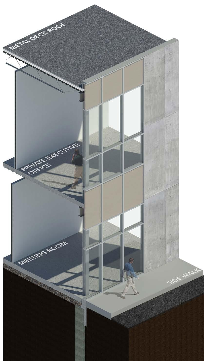
21 1 A 11 2 3 4 5 6 9 10 F.1 2.1 8.1 5.1 6.2 5.2 6.1 A.1 8 F B C D E E.1 D.1 1 A-7.0 1 A-5.1 1 A-7.1 2 2 1.97 3.232.942.943.231.97 (2 PEOPLE) 1 A-6.1 10.67 54.87 0.40 5.06 5.61 6.32 11.94 11.94 11.94 8.89 3.050.40 18.29 47.25 65.54 0.40 5.06 11.94 1.30 10.63 11.94 11.94 8.89 3.050.40 10.66 53.36 18.28 0.40 8.15 2.525.63 8.15 8.15 8.15 16.30 6.161.99 8.15 8.150.40 82.10 5.3 6.3 6.4 7 5.4 0.40 8.15 8.15 8.15 8.15 8.15 8.15 8.15 8.15 8.15 8.150.40 A.0 W5 W4 W4 W4 W5 W2 W1 W2 W1 W1 W1 W2 W2 W2 W2 W2 W2 W2 W3 W3 W3 W3 W3 W3 W3 W2 W2 82.30 34.84 3.226.173.22 34.84 30.00 30.00 65.54 F2 TYP. 200mm x 200mm HSS COLUMN TYP. 200mm x 200mm WIDE FLANGE COLUMNS ON PERIMETER 91.69° 90.00 91.69° 90.00 W1 1.95 3.34 1.421.591.42 19.59 1.421.591.42 1.96 6.311.421.541.42 10.44 17.65 1.421.541.426.311.96 3.26 1.171.421.171.427.89 1.95 W3 11.86 1.591.421.591.42 19.59 1.421.591.423.451.94 19.22 1.95 ACTUAL NORTH N CONSTRUCTION CONCRETE CURTAIN WALL: WALL, 200mm THICK 'SANDWICH BETWEEN CONCRETE PANELS WALL TYPE W1 W2 W3 W4 W5 W6 W7 W8 REINFORCED CONCRETE SLAB: SLAB ON 6 MIL. POLYETHYLENE SOIL STEEL COMPOSITE DECK SLAB: DECK FLOOR TYPE F1 F2 Project number Due Date STUDIO PROFESSOR: ARCHITECTURAL TECHNOLOGY ARCH 2005 JUSTIN J. HORVATH A-3.2 SECOND FLOOR PLAN PROJECT GBC 1 : 200 LEVEL 2 A 5 6 5.1 6.2 5.2 6.1 A.1 8 B 1 A-5.0 1 A-7.0 5.3 6.3 6.4 7 7.29 5.4 5.93 1.32 6.14 2.79 3.80 1.50 1.45 3.19 4.37 1.20 3.50 3.04 12.24 7.31 6.15 2.91 4.23 2.25 3.56 1.32 5.93 3.05 3.22 1.20 0.29 0.39 4.00 A.0 7.00 8.15 8.15 8.15 1.09 1.31 2.75 1.10 2.50 1.12 2.35 1.30 0.26 8.89 3.05 0.40 4.84 3.23 1.97 8.15 1.97 3.23 2.94 2.94 3.23 8.89 3.05 3.23 4.84 F2 F2 F2 W8 F2 F2 F2 W2 W1 W1 W1 W1 W2 W4 W5 W4 W6 W6 W6 W6 W8 W6 W8 W6 W6 W6 W6 W6 W6 W4 W6 W6 W4 W6 W6 W6 W5 W5 W6 W6 W6 W4 W5 W4 W5 W4 W4 W5 W5 W6 W6 W6 337 m² PRIVATE EXECUTIVE OFFICE FOR PRESIDENT 11 m² OPEN OFFICE AREA FOR ACCOUNTS RECEIVABLE/PAYABLE STAFF 9 m² OPEN OFFICE AREA FOR TEMPORARY STAFFING 91.69° 91.69° 90.00 90.00 PRIVATE EXECUTIVE OFFICE FOR PRESIDENT PRIVATE EXECUTIVE OFFICE FOR VICE PRESIDENT (SALES) SHARED OFFICE FOR ACCOUNTING (2 PEOPLE) PRIVATE OFFICE FOR ACCOUNTS MANAGER KITCHENETTE UNIVERSAL BARRIER-FREE W.C. STAFF TRAINING ROOM (15 PEOPLE) PRIVATE EXECUTIVE OFFICE FOR VICE PRESIDENT (MARKETING) W.C. W.C. 29 m2 21 m2 18m2 13m2 10m2 11m 5m2 5m 3.45 27m2 23m2 0.13 0.13 DN DN DN ACTUAL NORTH N SLAB ON MIL. POLYETHYLENE SOIL STEEL COMPOSITE DECK FLOOR TYPE F1 F2 WALL, 200mm THICK ALUMINIUM CURTAIN SIDING, 25mm AIR WALL TYPE METAL STUD WALL: ACOUSTIC INSULATION, OF THE ASSEMBLY INTERIOR GLAZED ALUMINUM FRAME W1 W2 W3 W4 W5 W6 W7 W8 Scale Project number Due Date Drawn by Checked by STUDIO PROFESSOR: ARCHITECTURAL TECHNOLOGY ARCH 2005 JUSTIN J. HORVATH A-6.1 CALL-OUT PLANS SECOND OFFICE PROJECT GBC 1 : 50 A-6.1 CALL-OUT PLAN OF SECOND FLOOR OFFICE 1
CALL OUT PLANS OF OFFICE FLOOR N N
SECOND FLOOR PLAN


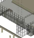
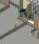
22 George Brown College (2023-2024) LEVEL 1 116.50 LEVEL 2 120.76 TOP OF STRUCTURAL STEEL 126.20 TOP OF PARAPET 126.79 1 11 2 3 4 5 6 9 10 2.1 8.1 5.1 6.2 5.2 6.1 4.26 5.440.59 10.29 8 W2 W2 Grade W2 W2 W2 W2 1 A-5.0 1 A-7.0 2 A-7.1 7 2.40 2.17 SP SP SP SP SP SP SP SP SP SP SP SP W1 VP VP VP VP SP SP SP SP W1 2.40 0.96 1.861.442.341.29 2.17 W1 TOP OF STRUCTURAL STEEL 5.26.1 0.59 A-4.0 NORTH ELEVATION A-4.0 SOUTH ELEVATION 2 LEVEL 1 116.50 LEVEL 2 120.76 TOP OF STRUCTURAL STEEL 126.20 TOP OF PARAPET 126.79 1 11 2 3 4 5 6 9 10 2.1 8.1 5.1 6.2 5.2 6.1 4.265.440.59 10.29 8 W2 W2 Grade W2 W2 W2 W2 7 2.40 2.17 SPSPSPSPSPSPSPSPSPSPSPSP W1 SPSP SP SPSP SP SP W1 2.40 0.96 1.861.442.341.29 2.17 W1 LEVEL 1 116.50 LEVEL 2 120.76 TOP OF STRUCTURAL STEEL 126.20 TOP OF PARAPET 126.79 1 11 2 3 4 5 6 9 10 2.1 8.1 5.1 6.2 5.2 6.1 0.59 5.44 4.26 10.29 8 W3 W3 W3 W3 W3 Grade 2.11 2.11 4.26 2.11 2.11 0.90 1 A-5.0 1 A-7.0 2 A-7.1 7 1.22 2.13 1.22 2.13 1.22 2.13 1.22 2.13 1.22 2.13 1.22 2.13 1.22 2.13 1 : 200 A-4.0 NORTH ELEVATION 1 A-4.0 SOUTH ELEVATION 2 LEVEL 1 116.50 LEVEL 2 120.76 TOP OF STRUCTURAL STEEL 126.20 TOP OF PARAPET 126.79 A F.1 A.1 0.59 5.44 4.26 10.29 F B C D E E.1 D.1 W2 W3 W2 W2 Grade 3.01 4.26 2.11 1 A-5.1 1 A-7.1 2 A-7.0 SP SP SP A.0 1.22 0.90 2.43 METAL SOFFIT PRE. FIN. METAL COVER AROUND EXTERIOR COLUMNS 3.65 0.91 1.83 2.39 1.22 2.13 1.22 PRE. FIN. SUSPENDED EAST ELEVATION 1 WEST ELELVATION LEVEL 1 116.50 LEVEL 2 120.76 TOP OF STRUCTURAL STEEL 126.20 TOP OF PARAPET 126.79 A F.1 A.1 0.59 5.44 4.26 10.29 F B C D E E.1D.1 W2 W3 W2 W2 Grade 3.01 4.26 2.11 1 A-5.1 1 A-7.1 2 A-7.0 A.0 1.22 0.90 2.43 METAL SOFFIT AROUND EXTERIOR 3.65 0.911.832.391.22 2.131.22 LEVEL 1 116.50 LEVEL 2 120.76 TOP OF STRUCTURAL STEEL 126.20 TOP OF PARAPET 126.79 A F.1 A.1 0.59 5.44 4.26 10.29 F B C D E E.1 D.1 W2 W3 W2 W2 Grade 2.11 4.26 2.11 4.26 1 A-5.1 1 A-7.1 2 A-7.0 W1 A.0 PRE. FIN. SUSPENDED METAL SOFFIT PRE. FIN. METAL COVER AROUND EXTERIOR COLUMNS 2.13 1.22 2.13 1.22 2.13 1.22 1 : 200 A-4.1 EAST ELEVATION 1 WEST ELELVATION NORTH ELEVATION SOUTH ELEVATION EAST ELEVATION WEST ELEVATION BUILDING SECTION LEVEL 1 116.50 LEVEL 2 120.76 TOP OF STRUCTURAL STEEL 126.20 TOP OF PARAPET 126.79 A F.1 A.1 F B C D E D.1 US FTG 115.28 1 A-5.1 2 A-7.0 0.59 5.44 4.26 1.22 11.51 2 A-8.0 3 A-8.1 A.0 2.14 2.11 2.11 2.11 3.05 2.21 Grade WAREHOUSE LOBBY OFFICE FOR ACC. MANAGER MEETING ROOM (20 PEOPLE) W1 W6 W4 W3 W1 W6 F2 F2 F2 W6 F2 W8 PRE. FIN. SUSPENDED PRE. FIN. METAL COVER COLUMNS 3.65 1 : 200 A-5.0 BUILDING CROSS SECTION 01 1
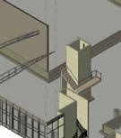
23 ISOMETRIC VIEW Office Area
Parapet
3D Printing
Detail
The Hillcrest Community School Art Studio
Program Course Location _Community School Art Studio
Production Period Award
_Architectural Technology Studio 3
SketchUp, Photoshop, Twinmotion _Indesign, Illustrator
_ 750 Davenport Rd, Toronto, Canada
_November 2023 - December 2023 _A+ Grade
Submission
Project Description
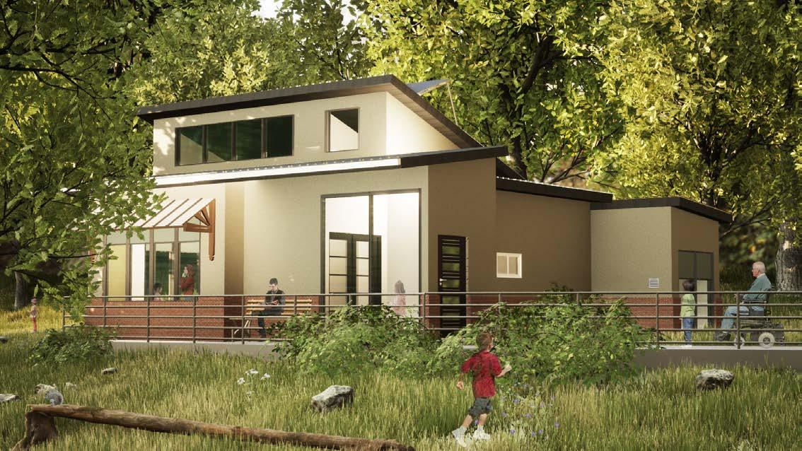
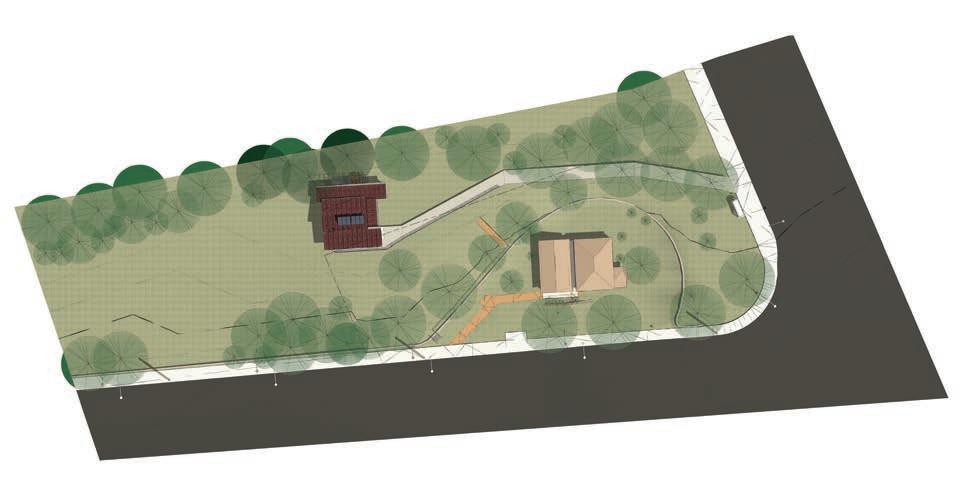
This is a design-focused project where the student must explain sustainable design features. For the final submission, the student is also required to produce a presentation-style document, including the site analysis, diagrams, and presentation drawings.
24 George Brown College (2023-2024)
04
2000mm wide exsisting walkway Access from the Bathurst Street with 1500mm wide path Existing Bench Exsisting bus stop A concrete wall approximately 1500mm in height
STREET
ROAD N Existing wood stairs accessed to the Davenport Road
trees
broken and fallen, necessitating a check of the surrouding trees’ condition before constructing a building A few new trees has been planted
fence The area lacks fencing and there are no stairs for access to the road A bike share station capable of accommodating around 30 bikes Existing lamp post
BATHURST
DAVENPORT
Several
have
Existing
The Hillcrest Community School Art Studio
_Individual
Member
Front
Tollkeepers’ Cottage Museum
_AutoCAD,
Software
View


Easy access to the outdoor space fosters a welcoming environment for external activities
By strategically placing the kitchen and bathrooms close together, efficient water supply management is achievable when accessing from bathurst street, the interior of the gallery space is visible
The entrance circulation has been simplified to ensure smooth wheelchair access to the art studio
25
entire building's volume 1 Designing roof slopes with consideration for each room's height and natural lighting Strategically placing windows and creating access to Bathurst Street Considering the size of each room and their interrelation, centered around the art studio 2 3 4
Grasping the
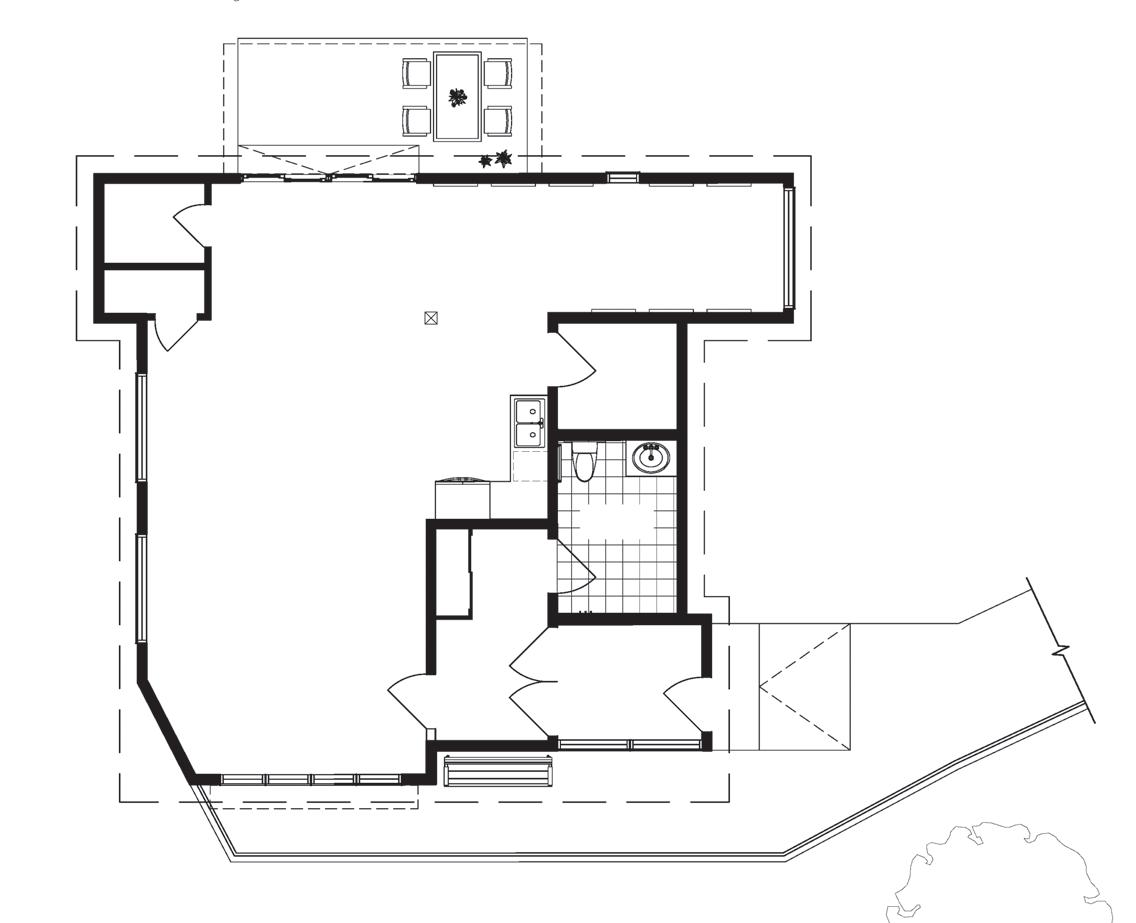
sunlight primarily enters through these windows and the roof window Art Studio Space Kitchenette Outdoor Area F DW Canopy Gallery Space General Storage Room Supplies Storage Closet Mech. Room Access to the
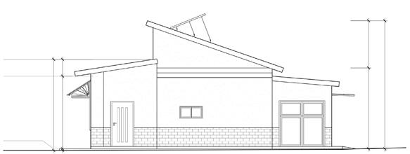
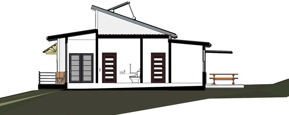
street Entry Vestibule Universal Washroom Entry Foyer CL Canopy N 750 2972 107 GRADE TOP OF PLATE TOP OF ROOF FIN. FIRST FLOOR 3831 716 3103 68 3456 5470 2014 3887 GRADE TOP OF PLATE TOP OF ROOF FIN. FIRST FLOOR The roof window above the art studio provides ample natural light, reducing the need for artificial lighting Especially in summer, a canopy is used to shield the art studio from direct sunlight
During the day,
bathurst
sunlight Solar
North
East
GROUND FLOOR PLAN
The segmented roof with gaps maximizes
Panels
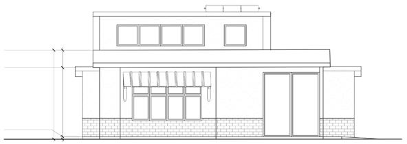
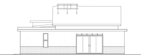
Eleation South Eleation
Eleation West Eleation
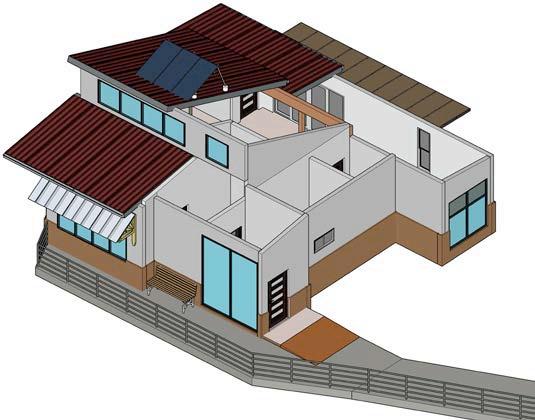
SUSTAINABLE DESIGN FEATURE (ISOMETRIC VIEW)
Enery Efficient Angled Solar Panels
High-Quality Fixed Window The Defender 76TS System
Fixed Canopy
4mm100%
Recycled Clay
WATER HARVESTING

Recycled Classic Metal Roof System
16” wide Universal Standing Seam panels made from 95% recycled materials with a fade and chalk-resistant finish, this design ensures durability and sustainability. The panels' 1.5” tall interlocking seams provide excellent watertightness, making them suitable for a variety of structures, including those with lower pitch roofs
High-Quality Slide Door
The Defender 88PH+ System, certified by the Passive House Institute. Crafted in Canada, it boasts a Uw value of 0.80 W/(m²K), offering a range of glazing options to suit diverse architectural needs.
EIFS Stucco Exterior Finish
Insulated StoPowerwall® – DrainScreen with Sto Crack Defense option for water resistive barrier.
Green Concrete Footpath 5” ECOPact Max Concrete offering up to 70%-90% lower CO2, produced in Canada. Min. Compressive Strength 2,500 psi with Warmly Yours Snow Melting System, including 3” free form type cable 3” apart.


26 George Brown College (2023-2024) Rain Water Tank with Filter Connecting
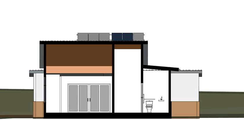
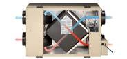
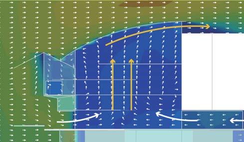
Road Entry Foyer Art Studio Entry Vestibule Universal Washroom Storage Closet Depending on the external environment (humidity, weather, temperature), ventilate the building by opening windows or using an air-to-air system Air to Air System (Hot Summer Day) Water Harvesting Air to Air Exchanger Air Purifier Fresh Air IN Hot Stale Air OUT
to the city sewer located beneath Davenport
features a 37 mm wide glazing cavity for triple pane IGUs, using thick glass layers (min. 4 mm – 3 mm – 4 mm) for optimal thermal
structural performance, designed to support the weight
demands of triple glazing.
and
and
Panasonic
EVPV400H Black 400W Solar Panel
supported Kseng aluminum triangle adujustable angle solar panel roof mounting system.
EverVolt™
with
on wood frame.
recycled metal awning
clay
local
Brick Crossroads Series recycled
bricks by Brampton Brick, made from
supply.
AIR TO AIR SYSTEM (HOT SUMMER DAY)
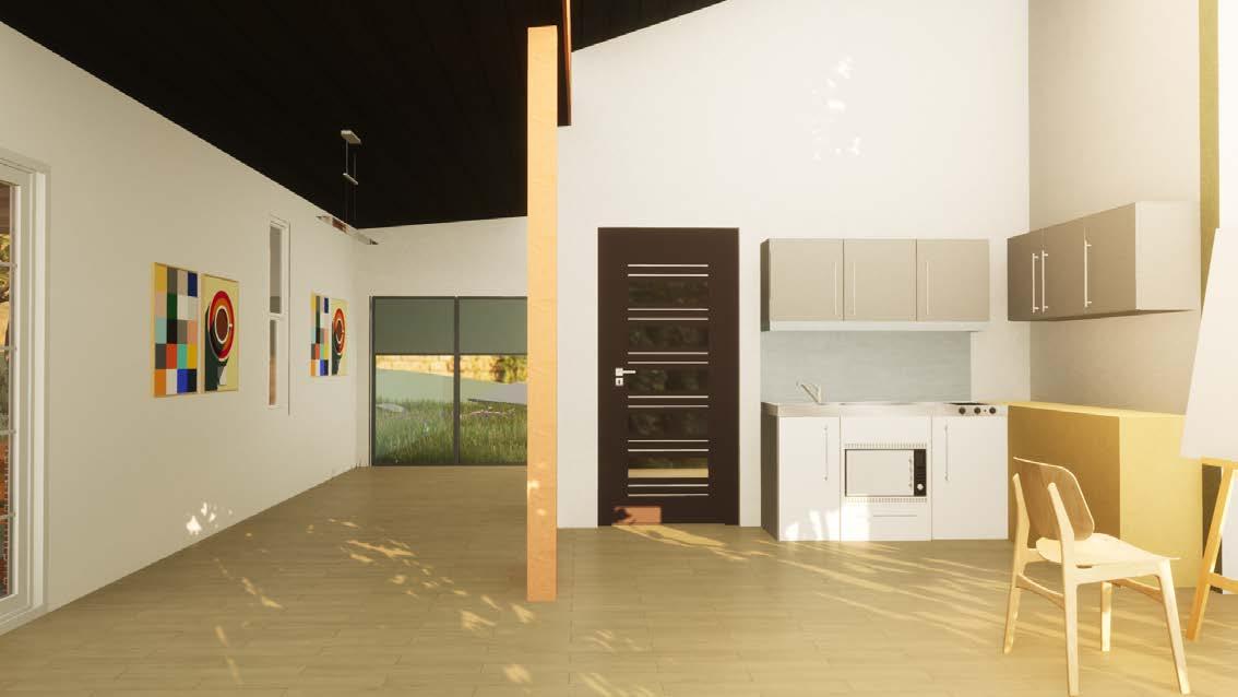
ART GALLERY & KITCHENETTE
27
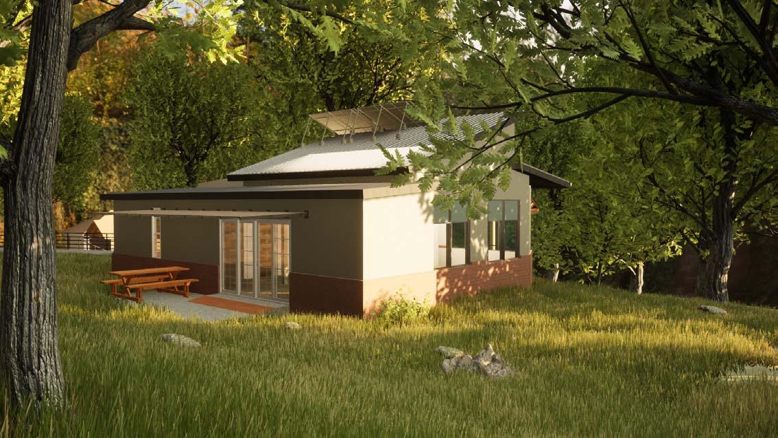
REAR
VIEW
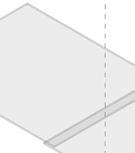
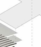
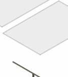
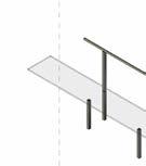
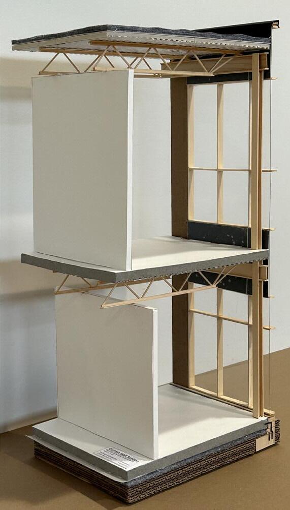
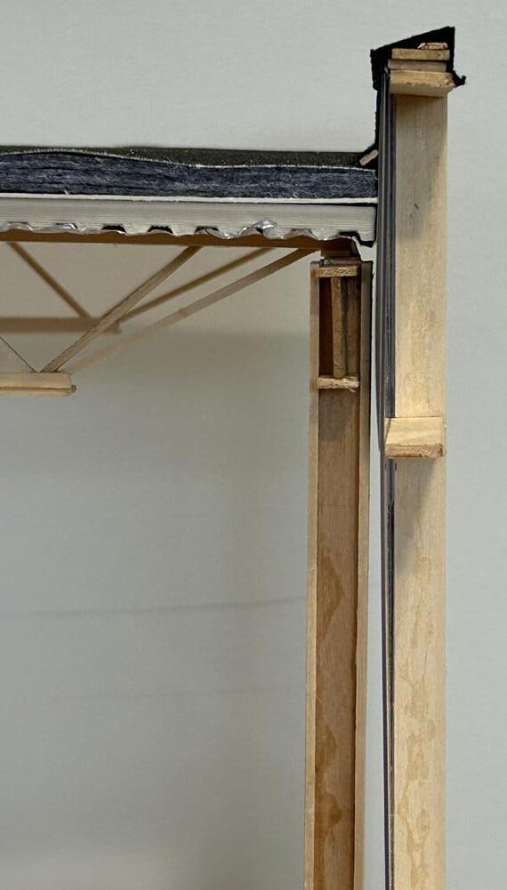
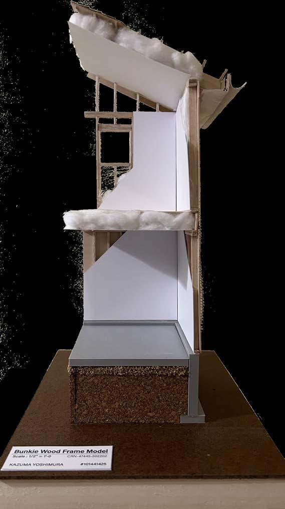
Wood Frame Model & Wall Section Detail
Program Course Location _Typical House
Award Member Software
Front Production Period
_Architectural Technology Studio 1
_January 2023 - April 2023
_N/A
_Selected as Top 3 in the Class
_A+ Grade
_Individual Submission
_AutoCAD
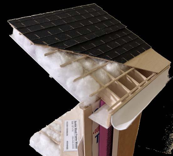
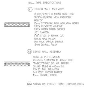
Specified Model Area
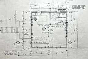
Project Description
The student must construct a specified corner from the drawing, understanding it to aid in model construction at a scale of 1/2”=1’-0” The model should show the framing methods and materials, such as Stucco, Wood siding, or Brick venner indicated by the professor in class.
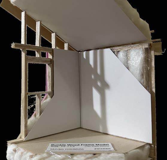
2nd Floor
28 George Brown College (2023-2024)
05
Roof
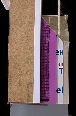
STUCCO EXTERIOR FINISH FOUNDATION WALL COAT FIBERGLASS REINFORCED MESH RIGID INSULATION AIR BARRIER PLYWOOD WALL SHEATHING Materials
MODEL AREA
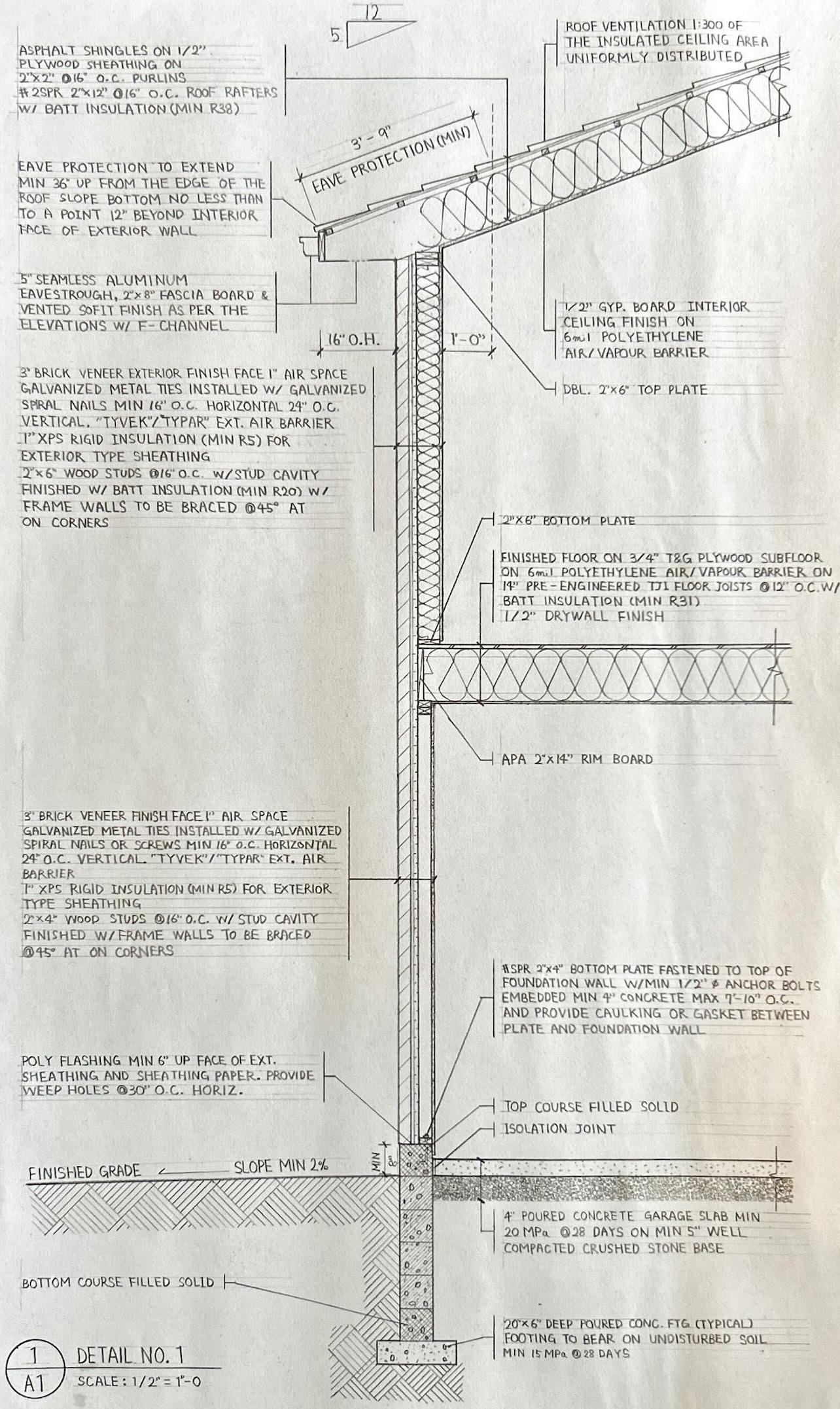
Wall Section Detail
Requirements
From underside of footing to roof
-8” Concrete block foundation wall, with 4” thick concrete garage slab
-20” x 6” Poured concrete footing
-3” Brick venner exterior finish
-2” x 4” @16” o/c wall stud
construction at a ground floor
-2” x 6” @16” o/c wall stud
construction at second floor
-Pre-Engineered 14” TJI @ 12” o/c floor joists, with 3/4” T&G plywood subfloor sheathing
Conventinally framed roof with:
-2” x 12” @16” o/c roof rafters
-2” x 2” @16” o/c cross purlins -Plywood roof sheathing
-2” x 6” fascia board
-16” finished overhang
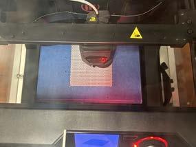
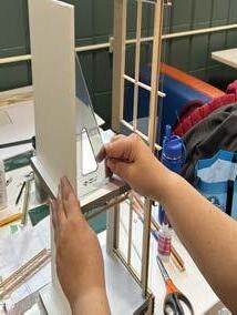
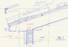
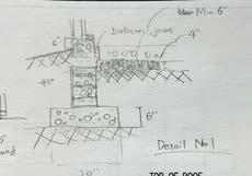
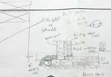
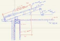
Processes/Sketches
29
01
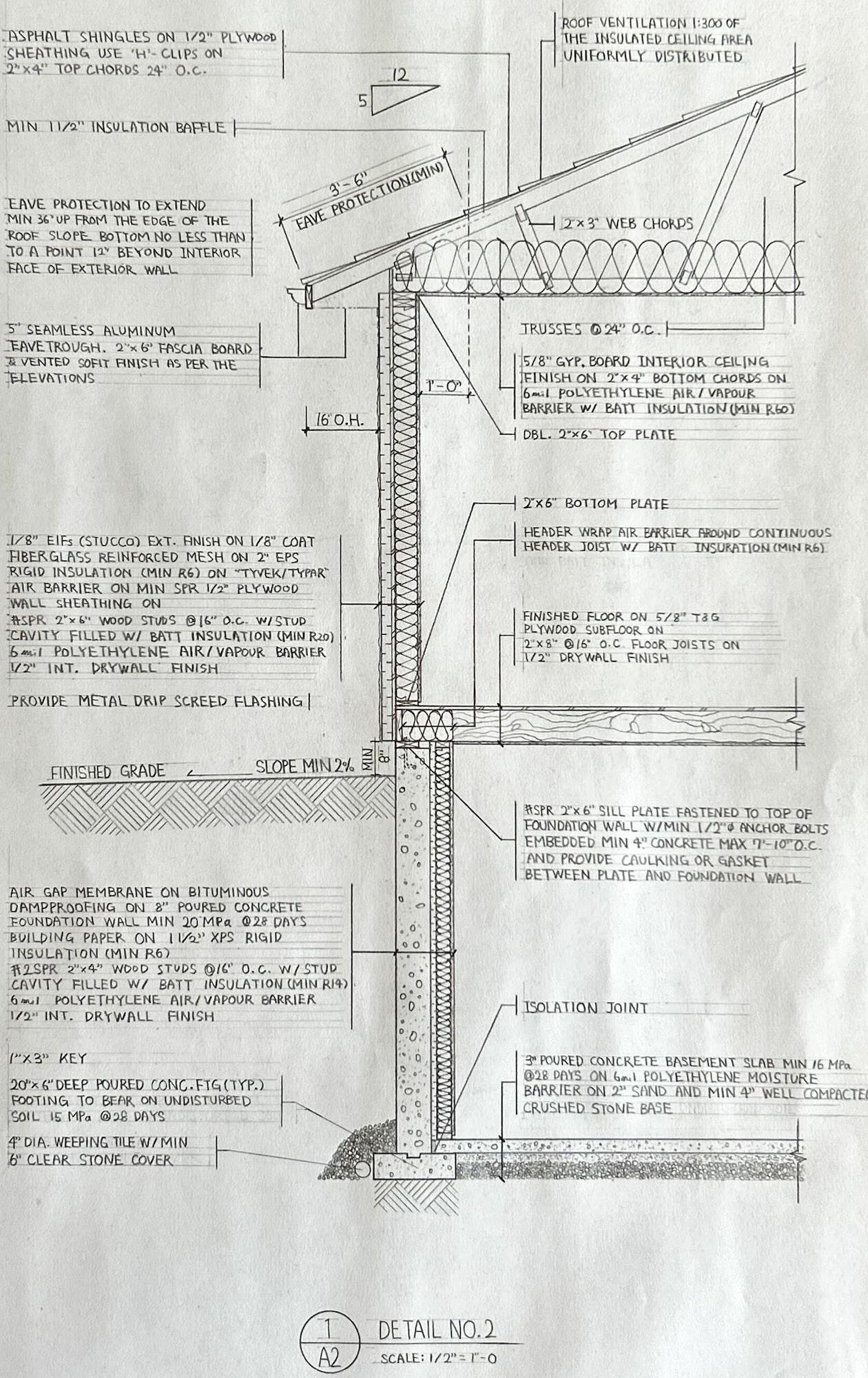
Requirements
From underside of footing to roof
-8” poured concrete foundation wall
-20” x 6” Poured concrete footing
-3” poured concrete basement slab
-2” EIFs (stucco) exterior finish
-2” x 6” @16” o/c wall stud construction at ground floor
-2” x 8” @12” o/c floor joists, with 5/8” thick T&G plywood subfloor sheathing
Roof framing:
-2” x 4” top and bottom chords
-2” x 3” web chords
-5/12 roof pitch
-Plywood roof sheathing
-2” x 6” Fascia board
-16” finished overhang
Processes/Sketches
30 George Brown College (2023-2024) Wall
Detail 02
Section
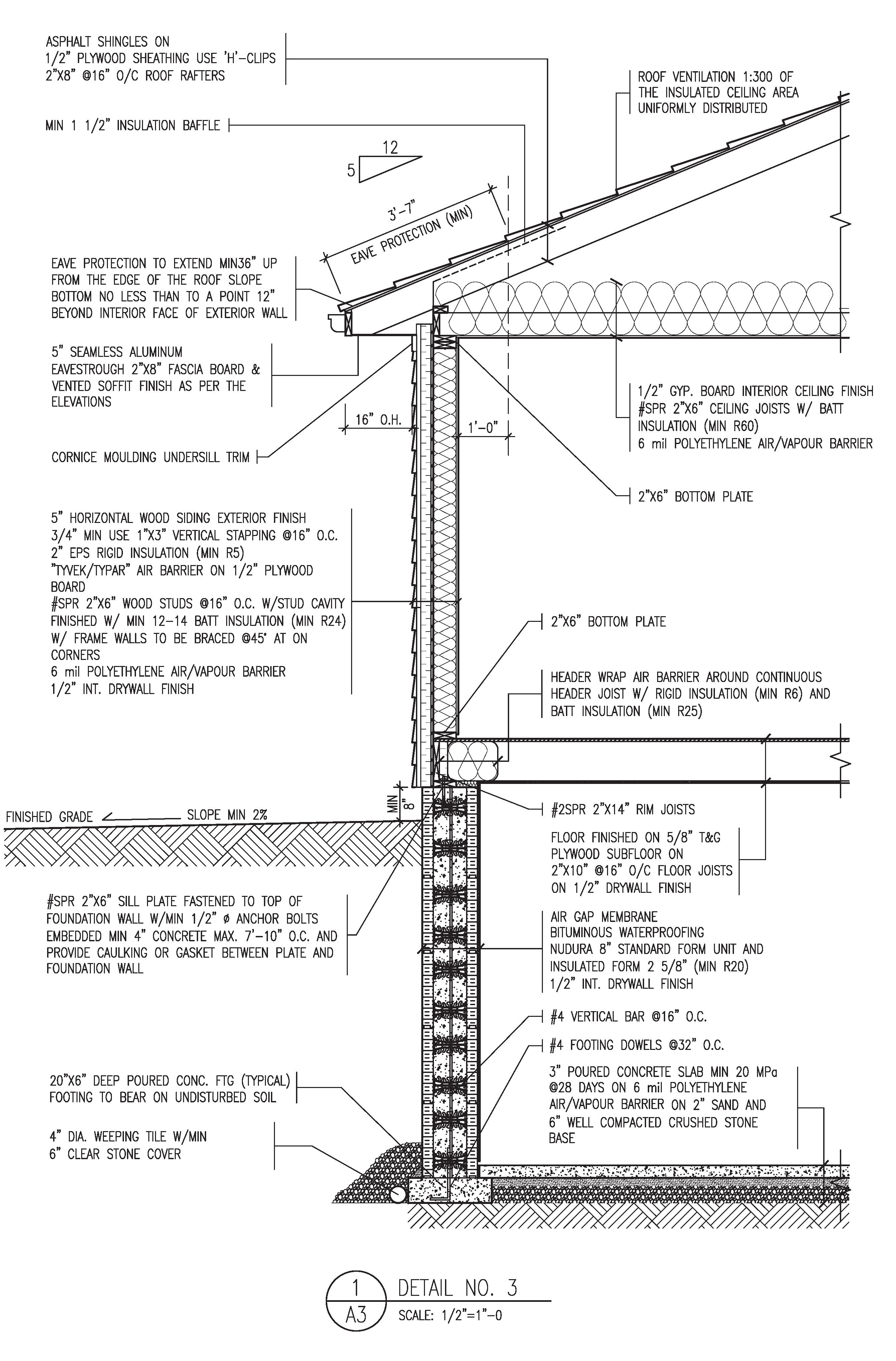
Requirements
From underside of footing to roof
-8” ICF poured concrete foundaiton wall
-20” x 6” Poured concrete footing
-3” poured concrete basement slab
-5” Horizontal wood siding exterior finish
-2” x 6” @16” o/c wall stud construction at ground floor
-2” x 10” @16” o/c floor joists, with 5/8” thick T&G plywood subfloor sheathing
Conventinally framed roof:
-2” x 8” @16” o/c roof rafters
-2” x 6” @16” o/c ceiling joists
-5/12 roof pitch
-Plywood roof sheathing
-2” x 6” fascia board
16” finished overhang
Processes/Sketches
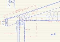
31 Wall Section Detail 03
Mix-used Commercial Building
Program Course Location _3 Storey House
Production Period Award Member
_Architectural Technology Studio 3
_September 2023 - November 2023
_Bloor St. West & Landowne Ave., Toronto, Canada
_A+ Grade
_Kayla Mccallum, Eunice Leung, Avery Peterson
_AutoCAD Software
Project Description
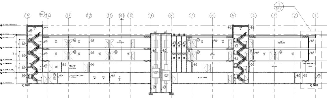
This is a group project where each member is required to communicate frequently to generate a single set of construction drawings. The building is a commercial building, which houses several tenants on the first floor, and residential units on the second and third floors. The project must be completed using AutoCAD only
*NOTE: This project is assigned to a group of four, with each member responsible for specific drawings. My drawings are as follows:

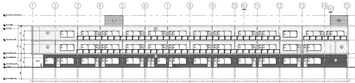
LONGITUDINAL SECTION
32 George Brown College (2023-2024)
06
SOUTH ELEVATION
33
N N
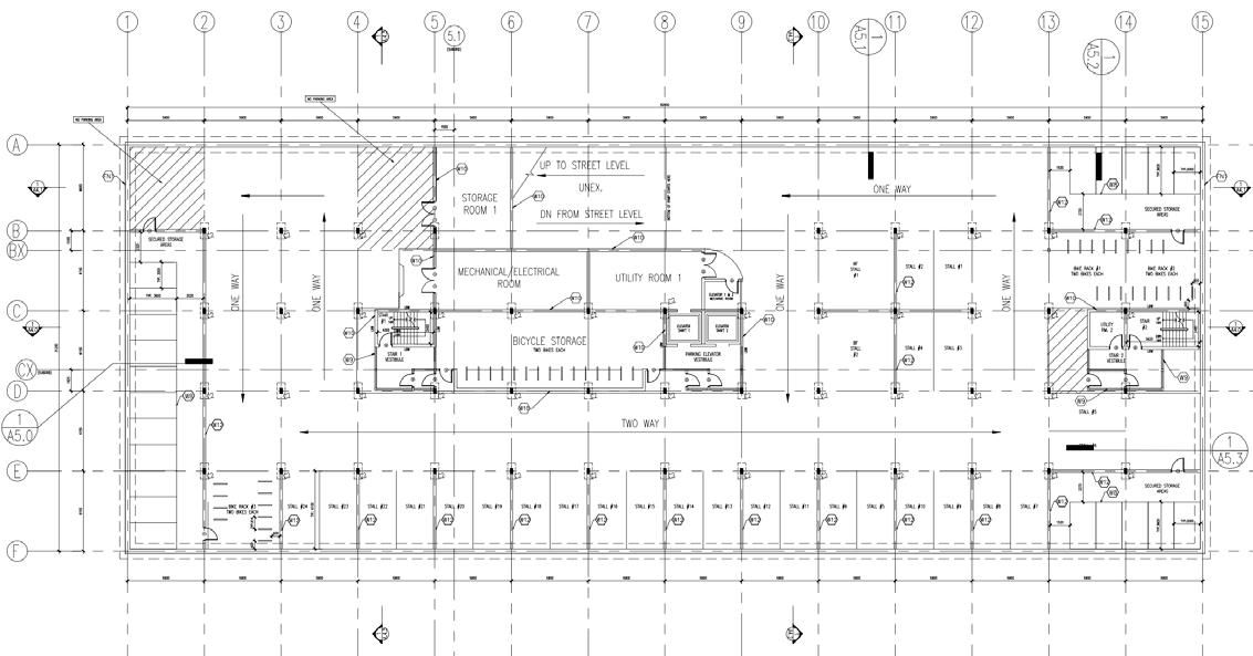
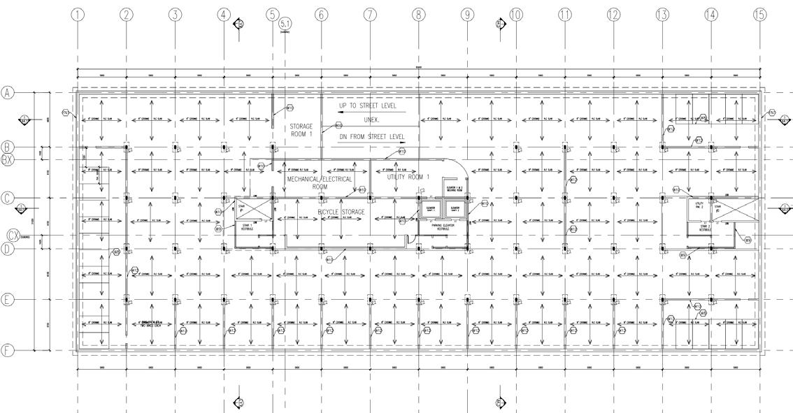
PARKING LEVEL PLAN STRUCTURAL FOUNDATION PLAN
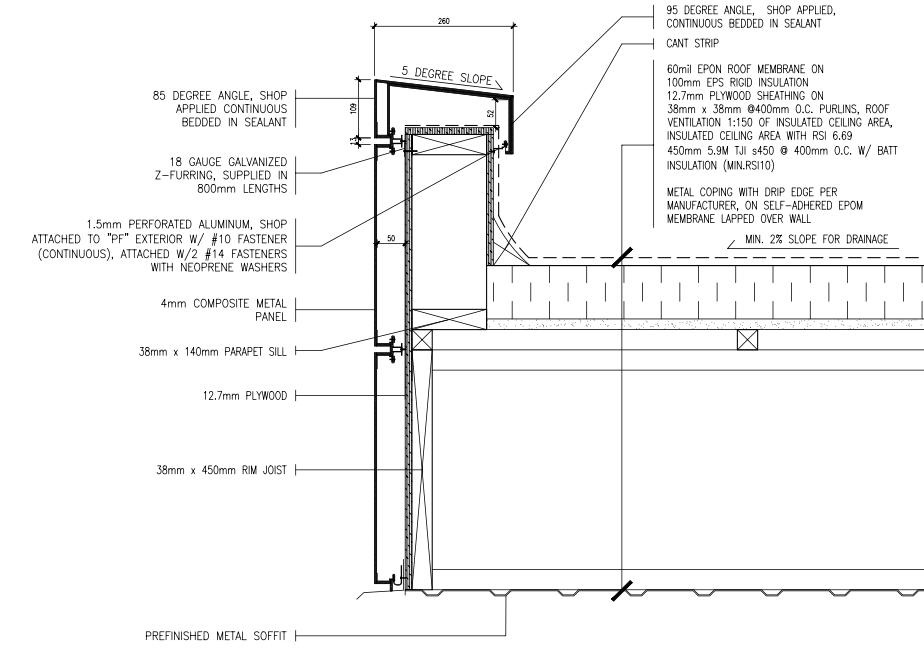
PARAPET SECTION DETAIL
34
Brown College (2023-2024)
George
DETAIL
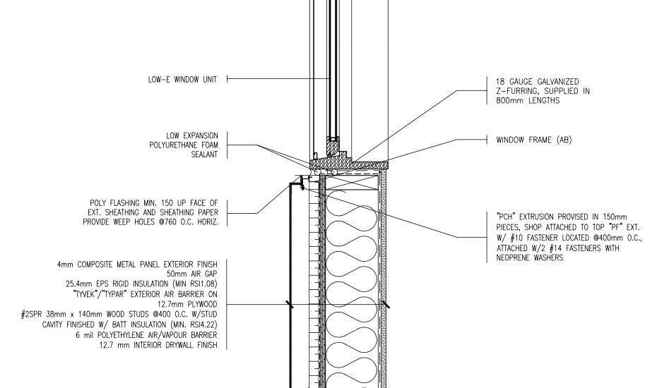
WINDOWSILL SECTION
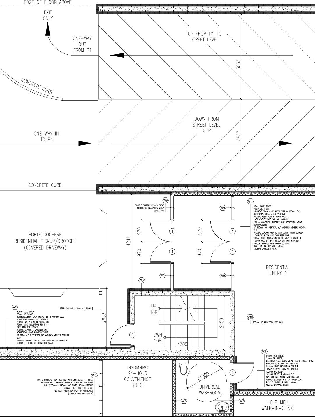
35 PLAN DETAIL OF MAIN ENTRANCE

Association for Building Environment Design
Aguri Scape
Program Course Location
Production Period Award
Member
_Residential with Urban Agricultural Area
_Master of Architectural Design Studio 1A
_January 2024 - February 2024
_Toyosu, Tokyo, Japan
_3rd Place
_Kosuke Terashawa, Mizuki Terashima,
_Naoto Katsube, Tatsuya Murakami
_Rhinoceros, SketchUp, Illustrator, Photoshop Software
Project Description:
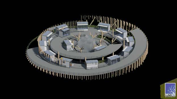
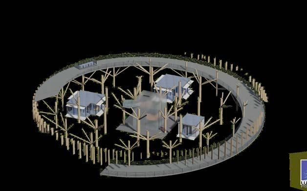
This design group project is located in central Tokyo, Toyosu. The area is filled with condominiums, which are highly profitable for developers. However, this development could lead to monotonous cityscape, a common sight in crowded cities. Students are tasked with exploring new urban paradigms, particularly from the perspectives of ‘Architecture x Transportation x Environment.’ They are encouraged to consider what living in the city contributes to the urban landscape.
1.Energy Station 2.Infrastructure


3.Share Energy

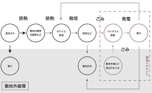
Our suggestion is for an experimental urban agricultural city with an energy infrastructure. We have divided our site into four areas connected by common grass greenhouses. This common space serves as an agricultural area that features different temperature zones, thus allowing residents to choose their preferred location and a variety of environments for vegetable cultivation.
36 Tokai University & Meiji University (2016-2021) 07
1 2 Concepts System for energy circulation
Remaning Heat Tokyo gas Building Common Space Vegetable Biomass Electricity High-temperature steam Cultivation Generators Off-site Electricity Off-site Organic Garbage Biomass Warm water Room temperature water
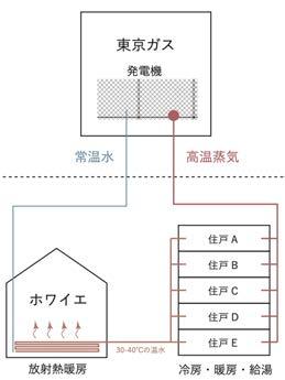
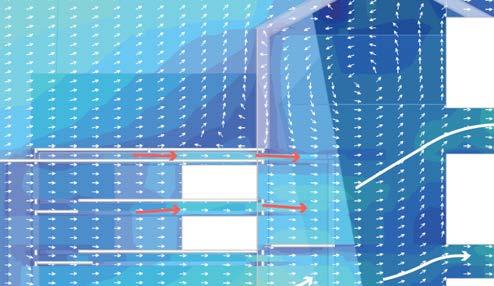
Heat & Transportation System
The three different lines of flow were designed to create comfortable circulation throughout the buildings
Logistics flow
Create temperature differences in each area so that a variety of vegetables can grow
37
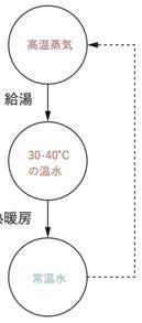
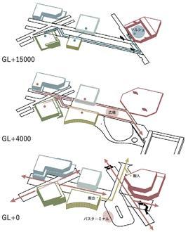
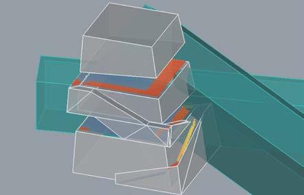
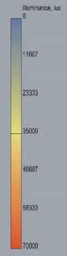
2 4 3 Utilize the heat energy Heat Analysis
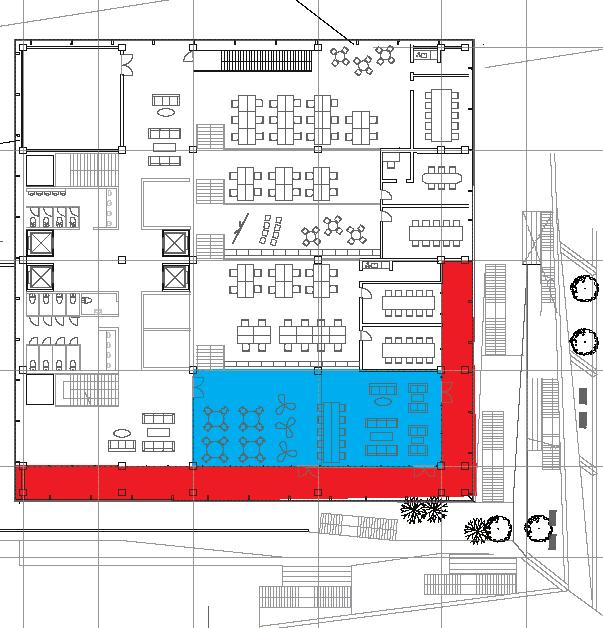
UP UP 保育園2F 住居エントランス Tokyo Gas Generator Room Temperture Water High Temperture Steam Common Space Dwelling Unit Radiant Heater A B C D E Cooling or Heating Summer Solstice Autumnal Equinox Winter Solstice 0(lux) 25000 50000 Area E Area A Area B Area D OVERALL SECOND FLOOR LONGITUDENAL CROSS SECTION LATITUDINAL CROSS SECTION GL + 15000 GL + 4000 GL + 0 Area C

38 Tokai University & Meiji University (2016-2021) SITE A
39 SITE B
40 Tokai University & Meiji University (2016-2021) SITE C
41 SITE D
The competition is sponsord by

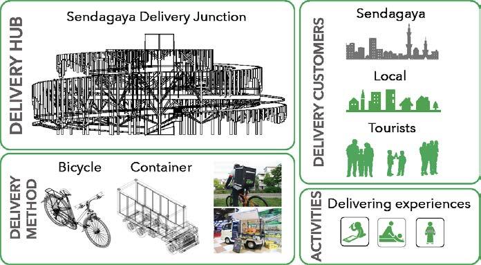
Sendagaya Delivery Junction
Program Course Location
Production Period Award
Member
_2020 Tokyo Olympic-related facility
_The 8th Hulic Student Idea Competition
_May 2020 - August 2020
_Sendagaya, Tokyo, Japan
_N/A
_Rhinoceros, Grasshopper, Illustrator, Photoshop Software
Project Description
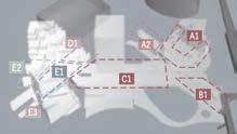
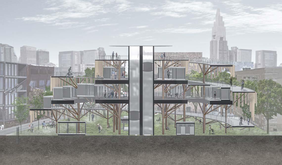
This is a student competition required to design a facility related to the 2020 Tokyo Olympics. Students must consider the program of the building and create a unique or iconic design. In addition to accommodating the expected high demand from tourism, the building should also meet their needs and consider how to utilize the location of Tokyo, Sendagaya
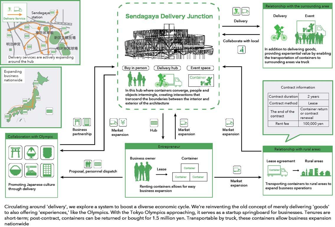
Delivery x Architecture
01 02
Since the onset of COVID-19, the demand for delivery services, such as UberEats and Amazon, has grown. With the expected increase in the number of tourists, we are focusing on ‘Delivery’ to design a facility that will be suitable for Sendagaya


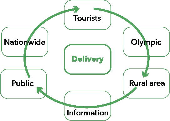
Definition of the ‘Delivery’
42 Tokai University & Meiji University (2016-2021)
08
_Daiki Furuyama, Sohei Yoshida
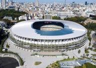
Olympic studium
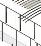
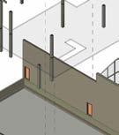
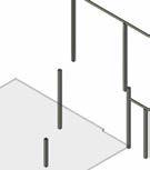
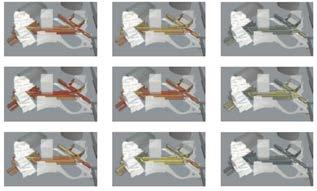
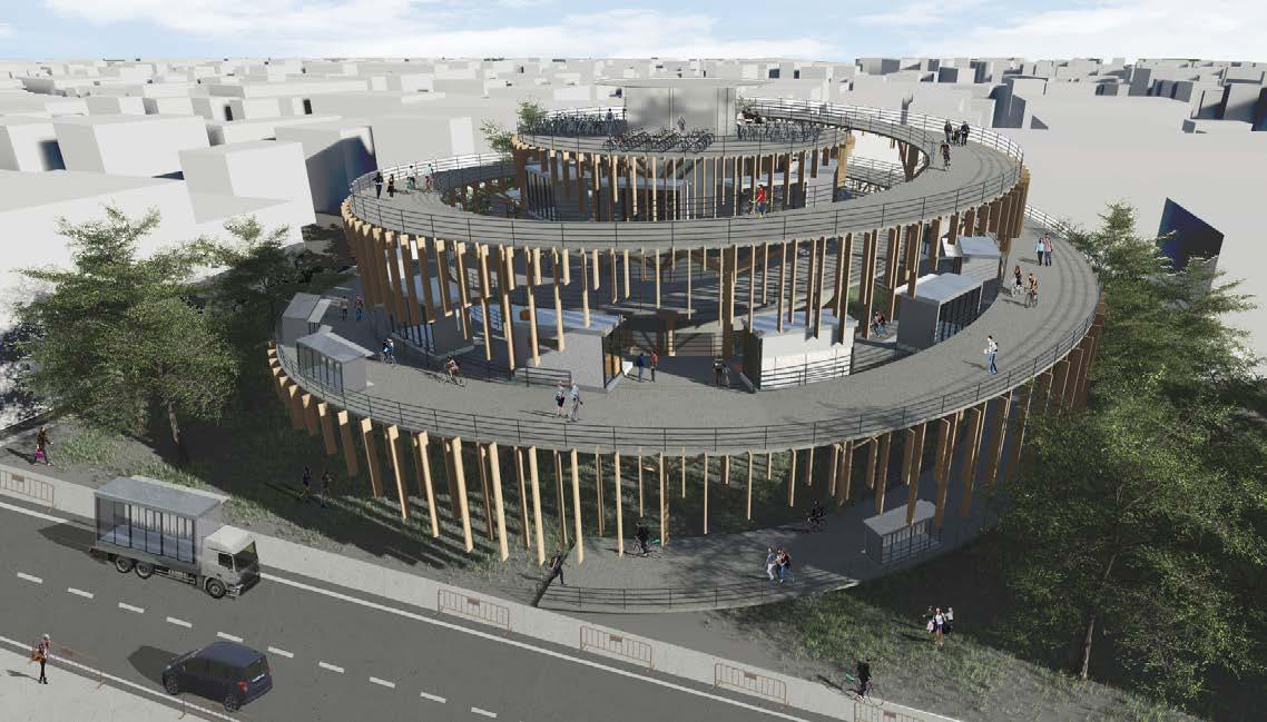
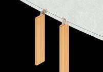
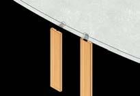
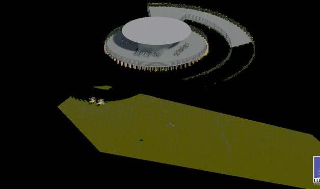
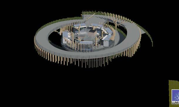
Slope and Container
The slope is equipped with wiring for power supply, and handrails to prevent falls
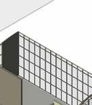
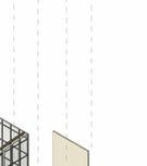
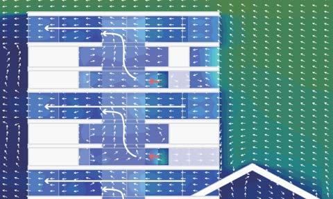
The lattice facade rotates depending on weather conditions and wind speed


Seamlessly altering the dimensions of the lattice to create closed sections and open approach areas.
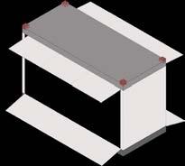
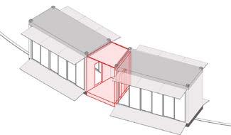
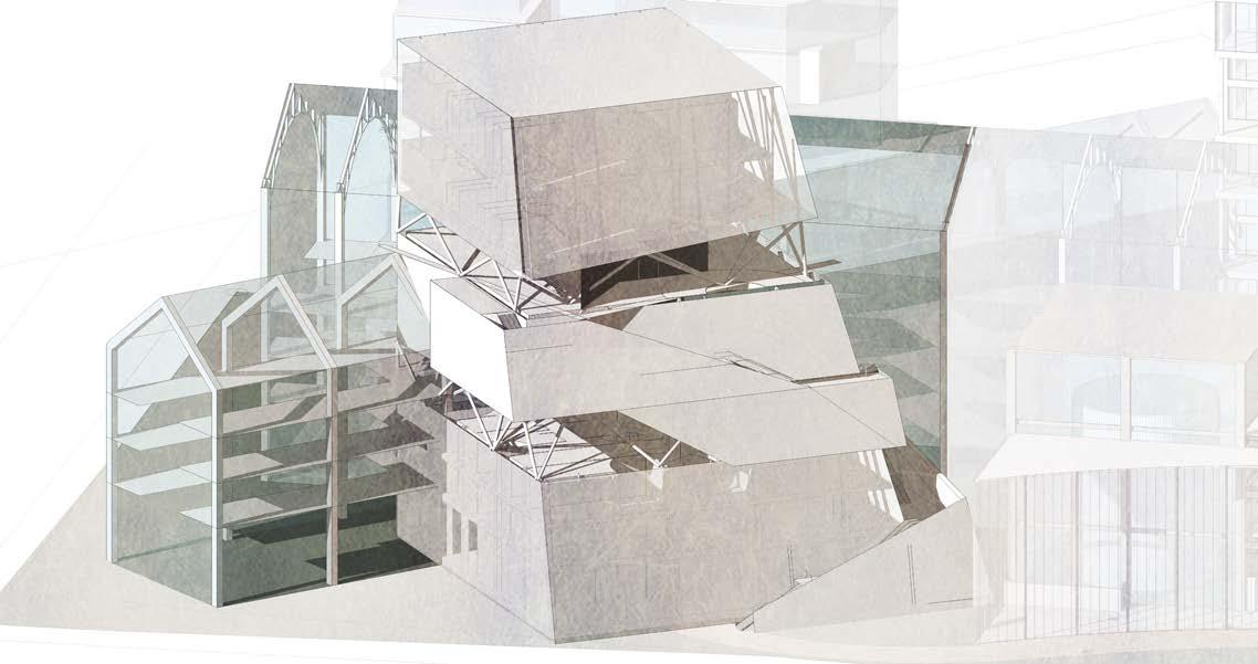
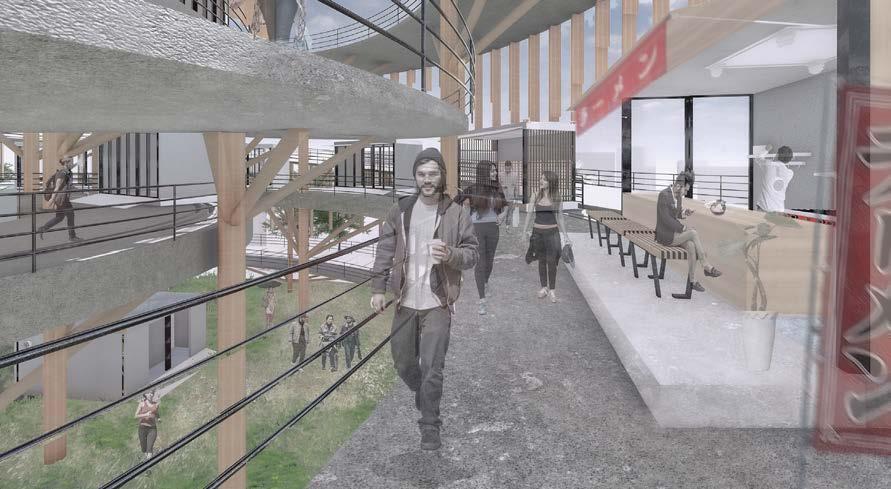
Containers are formed to dimensions that can be transported by truck. The structure uses a rigid frame unit construction method with heavy steel
A diverse range of circular businesses centered around delivery
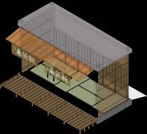
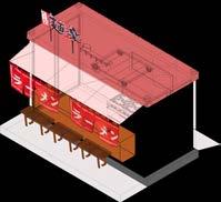
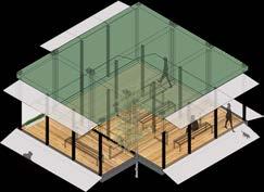
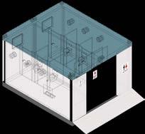
43 Container Open Close Close
04 03
Each container can be connected
Ramen shop
Tea ceremony (culture)
Public space
Washroom
4F: ROOF (BIKE STATION)
3F: CONTAINER AREA
2F: CONTAINER AREA
1F: OPEN SPACE
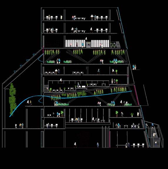
44 Tokai University & Meiji University (2016-2021) 1 2 3 BUILDING CROSS SECTION
People who get off the elevator have various purposes and run down the slope
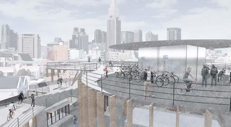
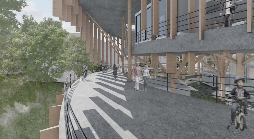
The slope is used as a path for people and bicycles
Containers located in the middle levels are used for various purposes and attract tourists
45 1 2 3
The competition is sponsord by
A Brick Home that Nurtures Assets
Program Course
Location
Production Period Award
Member
_Single Storey Residential Building
2nd Asahi Global Student Design Competition
_September 5th, 2020 - September 8th, 2020
_Yotsukaichi, Mie, Japan
_Honorable Mention with $500
_Daiki Furuyama
Software
Project Description
_Rhinoceros, Lumion, Illustrator, Photoshop
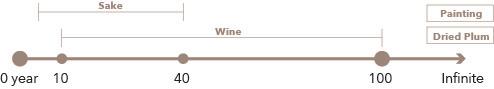
The theme of this competition is ‘Envisioning residential units constructed with bricks and preserving assets for 100 years.’ Participants need to explore how brick materials can be utilized to conceive new architectural designs. Furthermore, they should consider how to maintain assets throughout their lifespan. The project requires the design of 10 one-storey residential units and a shared space.
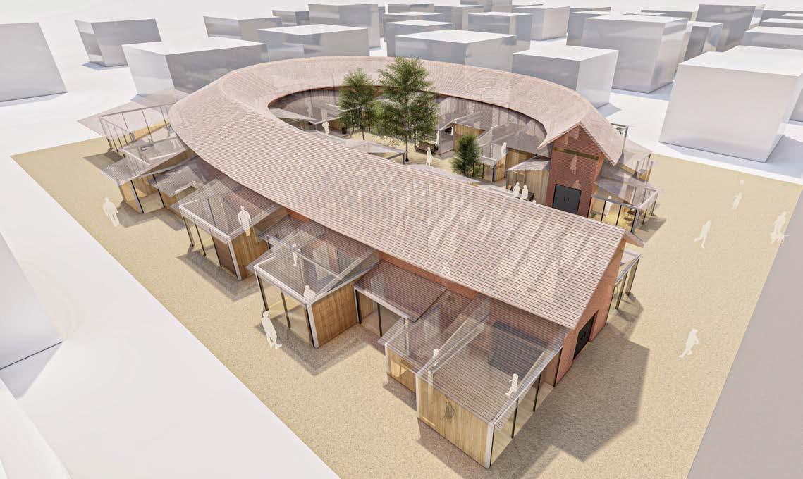
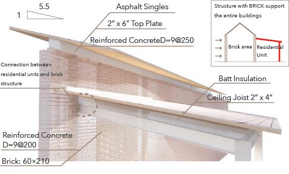
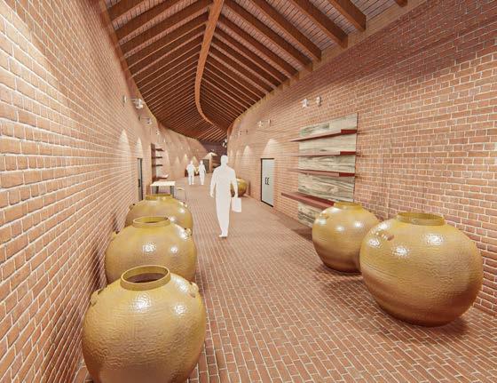
The brick features high heat storage capacity. Historically, bricks have been used in warehouses and fireplaces in Japan. Considering the competition theme, ‘Urban Assets in 100 Years,’ we are focusing on the topic of ‘asset preservation.’ Each residential unit sandwiches a public area where assets such as wire, sake, and paintings are preserved by the residents.


46 Tokai University & Meiji University (2016-2021)
09
A Brick Home that Nurtures Assets
Asset Preservation 1.
A. Dried Plum
C. Sake
B. Painting
Preservation (Aging) Period: 10-100 years Preservation (Aging) Period: Infinite Preservation (Aging) Period: 2-100 years Preservation (Aging) Period: Infinite
D. Winary


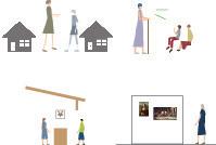
Make the relationships with neibors, people of city through variety of activities
Residents C (Sake)
Residents D (Winery)
Shared space (Event, Gathering space)
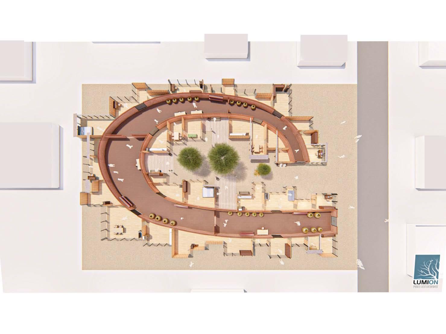
Residents B (Painting)
Line of Flow (Brick area)
Line of Flow (Public)
Residents A (Dried Plum) Shared
47 Street
space
events occur regularly
area
utilized for preserving assets
Preservation makes various connections The connecton between brick wall 2. 3. Manage the assets
:
Brick
:
The
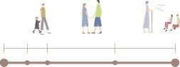
Age 0 5 20 65 100 Study Teach Event Neighbors Sell / Buy Events Exhibition
Sony Culture Box
Production Period
Program Course Location _Commercial Building
Award
Member
Architectural Design Studio 05
_May, 2018 - September 8th, 2020
_Ginza, Tokyo, Japan
_First Place
_Individual Submission
Software
Project Description
_Lumion, SketchUp, Photoshop, Illustrator
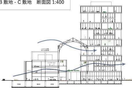
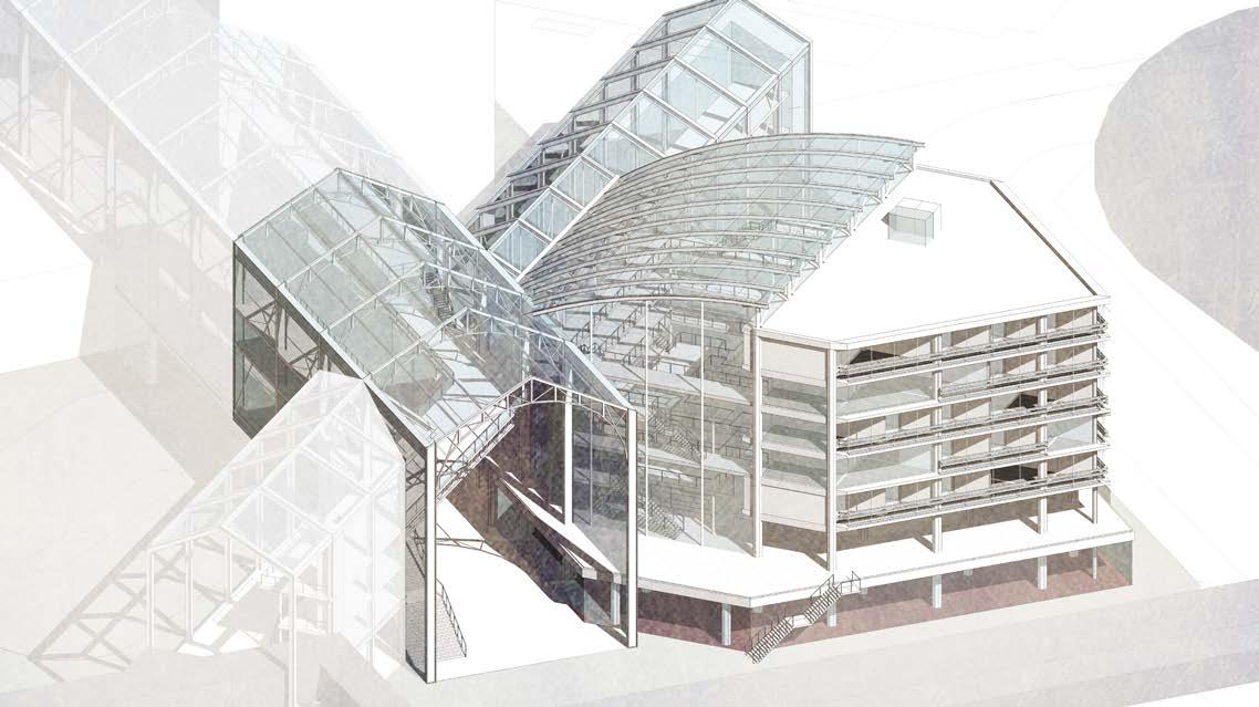
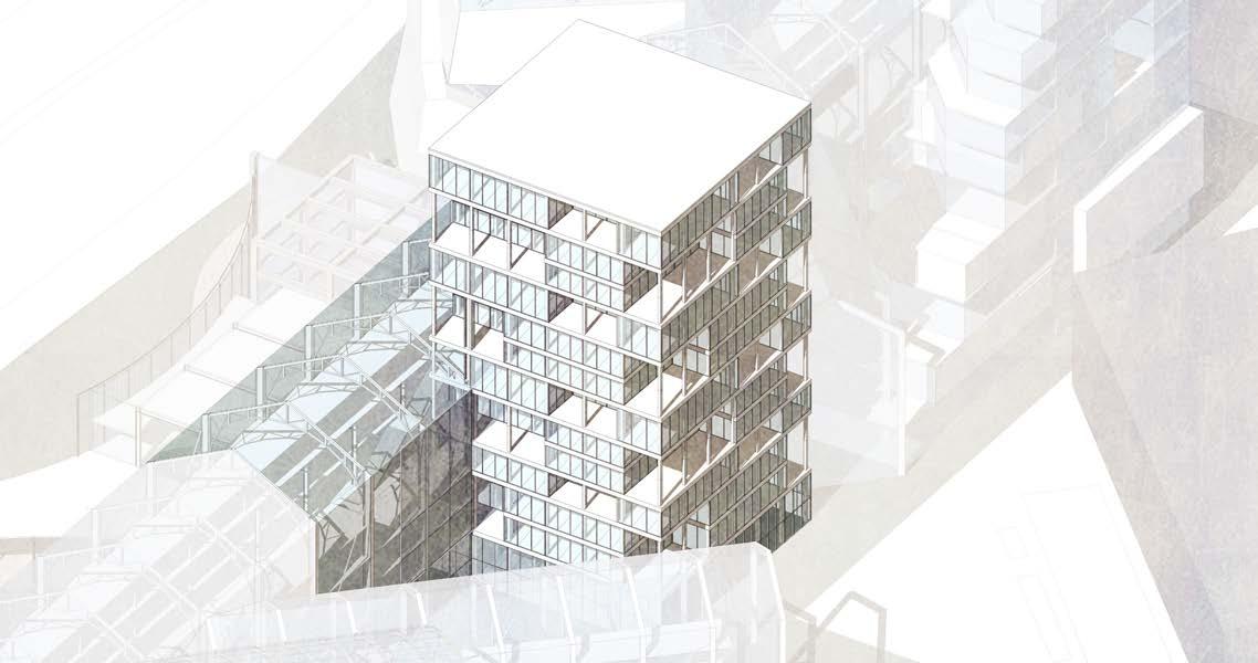
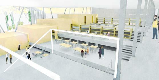
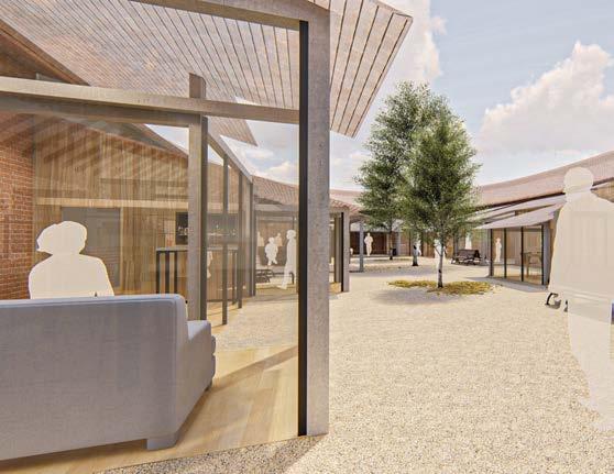
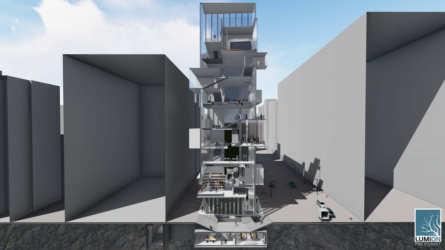
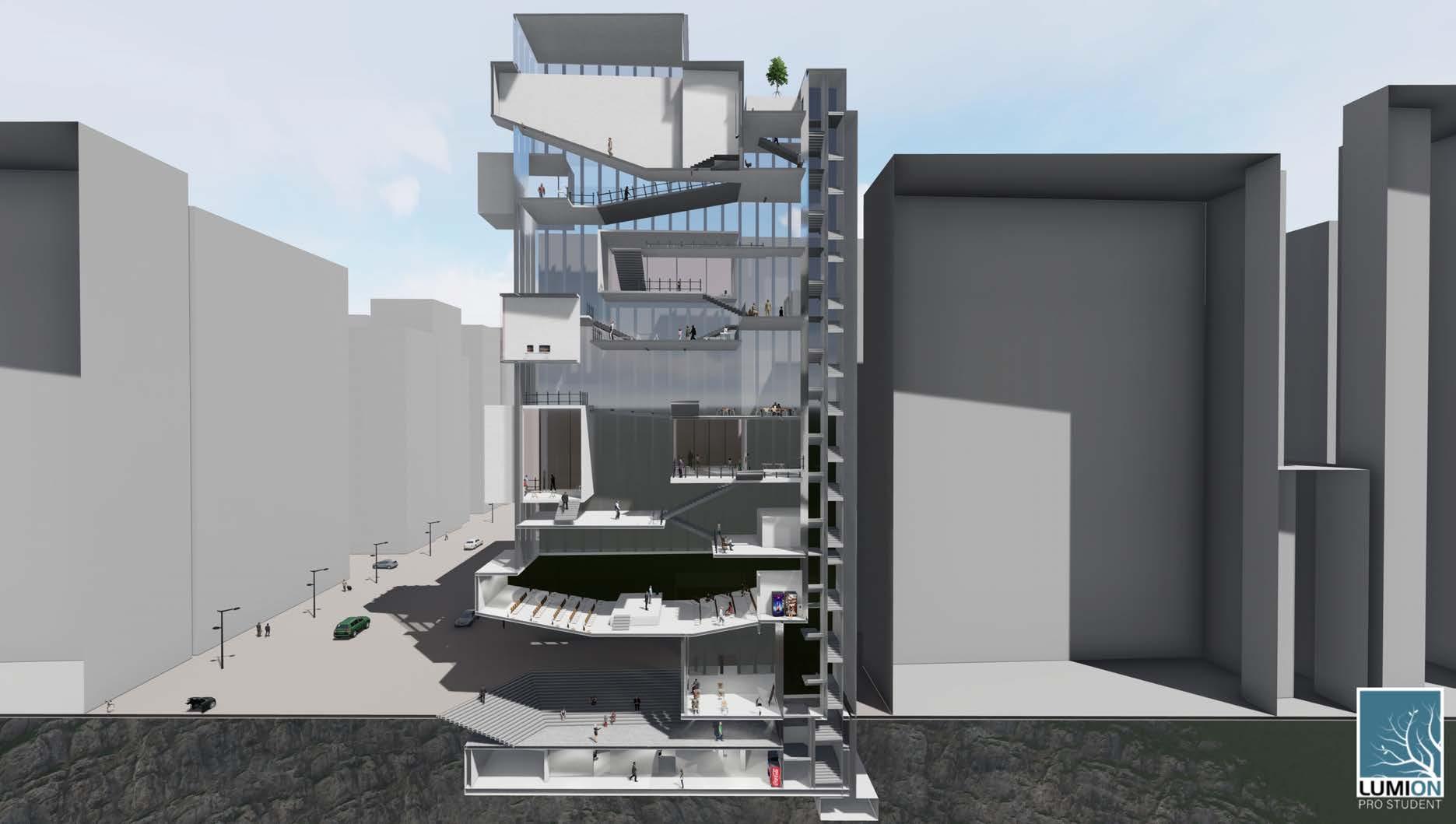
This project involves renovating the old Sony building into a new structure, located in a luxurious office and tourist area in central Tokyo. Students are required to design the New Sony Building, incorporating elements of Sony and Ginza culture into the architecture. The building must be 11 stories high and include an attractive public space.
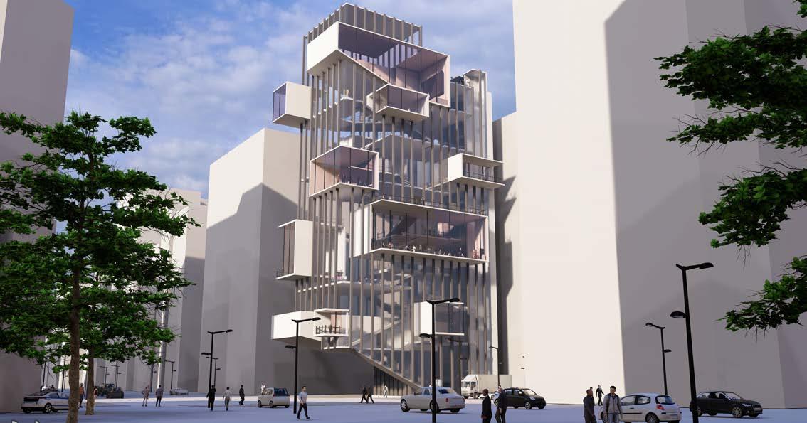


Ginza has evolved into a luxury district with an array of brands since the Showa era. The term “Ginbura” was coined to describe the experience of strolling and shopping while enjoying the scenic streets of Ginza. 1862 1867
flow
48 Tokai University & Meiji University (2016-2021)
1924 Now
The name ‘Ginza’ was born through (1862) From the students of that time, the term ‘Ginbura’ was born A town where Japan’s luxury converges With the plan for Ginza’s brick town, the main street was developed
10
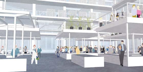
“GINBURA” The Public Area Attract People 1. 2. Strolling + Ginza = GINBURA
intersection Ginza Station
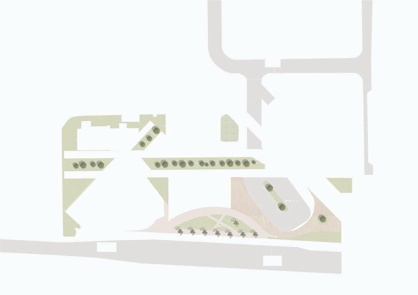
Public A B SITE PLAN N
Attract the
of people from
(B2)
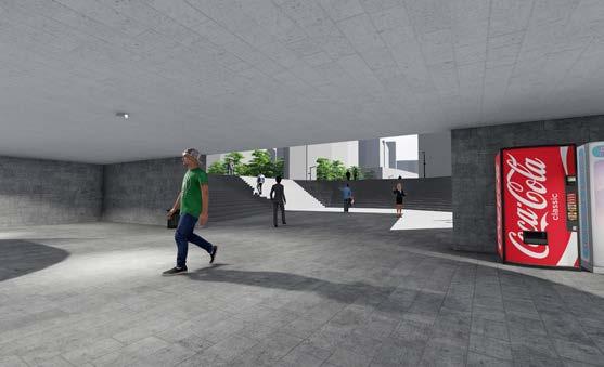
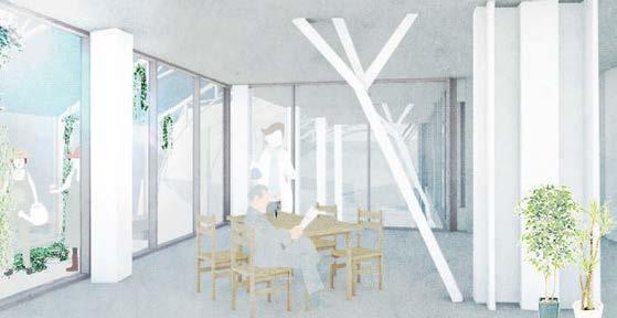
PUBLIC AREA
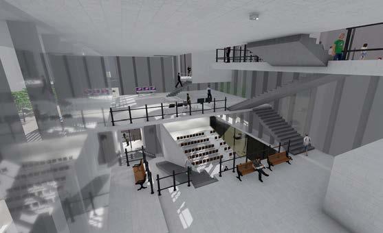
INTERIOR VIEW
49
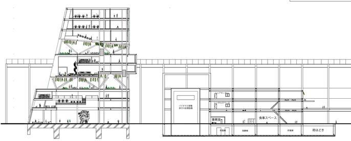
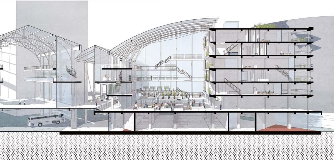
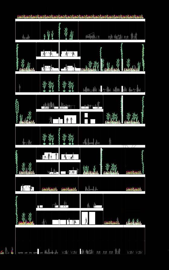
CROSS SECTION A CROSS SECTION B
Movie Theater Shop VR Area Shop Balcony Music Hall Public Area Office Access to the Ginza Station Product Display (Accessary) Product Display (Game) Cafe Foyer
Thank you
Kazuma Yoshimura kazuma.yoshimura0719@gmail.com
