
Contents
INTRODUCTION
Hydraulic systems
[35.000] Hydraulic systems
[35.518] Reel control system
[35.780] Feeder engagement system
[35.565] Cutter control circuit
[35.910] Head and header hydraulic drive
Electrical system
Harnesses and connectors
External lighting
Reel speed and position control
[55.421] Feeding control system
Chopping and cutting control systems
Attachments/Headers

Foreword - Important notice regarding equipment servicing
Safety rules
Safety rules
Safety rules - Ecology and the environment
T orque - Minimum tightening torques for normal assembly
T orque Standard torque data for hydraulics
Basic instructions - Shop and assembly
General specification
General specification
Product identification
Product identification - Machine orientation
Foreword - Important notice regarding equipment servicing
All repair and maintenance work listed this manual must carried out only qualified dealership strictly complying with the instructions and whenever the special
Anyone who performs repair and maintenance operations without complying with the procedures provided herein shall responsible for any subsequent
The manufacturer and all the organizations its distribution chain, including - without limitationnational, regional, local reject any responsibility for damages caused parts and / components not approved the facturer , including those used for the servicing repair the product manufactured marketed the manufacturer any case, warranty given attributed the product manufactured marketed the manufacturer case damages caused parts and / components not approved the manufacturer
The information this manual - - date the date the the policy the manufacturer for continuous Some information could not updated due modifications a technical commercial type, changes the laws and regulations dif ferent countries. case refer your NEW HOLLAND Sales and Service
Safety rules

Personal safety
This the safety alert used alert you potential personal injury Obey all safety messages that follow this symbol avoid possible death injury
Throughout this manual you will find the signal words W and CAUTION followed special These precautions are intended for the personal safety you and those working with
Read and understand all the safety messages this manual before you operate service the
DANGER indicates a hazardous situation not will result death serious injury
W ARNING indicates a hazardous situation not could result death serious injury
CAUTION indicates a hazardous situation not could result minor moderate injury
F AILURE T O FOLLOW
Machine safety
NOTICE: Notice indicates a situation that, not avoided, could result machine property damage.
Throughout this manual you will find the signal word Notice followed special instructions prevent machine property damage. The word Notice used address practices not related personal safety .
Information
NOTE: Note indicates additional information that clarifies other information this
Throughout this manual you will find the word Note followed additional information about a step, other information the The word Note not intended address personal safety property

Safety rules
General safety rules
Use caution when you operate the machine Raised full tanks and other loads will change the center gravity the The machine can tip roll over when near ditches and embankments uneven
Never operate the machine under the influence alcohol while you are otherwise
Hydraulic oil diesel fuel leaking under pressure can penetrate the causing serious injury
• NOT use your hand check for Use a piece cardboard paper
• Stop the remove the key , and relieve the pressure before you connect disconnect fluid
• Make sure that all components are good T ighten all connections before you start the engine surize the
• hydraulic fluid diesel fuel penetrates the skin, seek medical attention immediately .
• Continuous long term contact with hydraulic fluid may cause skin cancer A void long term contact and wash the skin promptly with soap and water
Keep clear moving Loose jewelry , long hair , and other loose hanging items can become entangled moving
W ear protective equipment when
NOT attempt remove material from any part the machine while being operated while components are
Make sure that all guards and shields are good condition and properly installed before you operate the Never operate the machine with shields Always close access doors panels before you operate the
Dirty slippery and platforms can cause Make sure these surfaces remain clean and clear
A person pet within the operating area a machine can struck crushed the machine its NOT allow anyone enter the work
Raised equipment and / loads can fall unexpectedly and crush persons Never allow anyone enter the area underneath raised equipment during
Before you leave the machine:
Park the machine a level
Put all controls neutral park lock
Engage the parking Use wheel chocks
Lower all hydraulic equipment header ,
T urn f the engine and remove the key
due exceptional you would decide keep the engine running after you leave the operator ’ s then you must follow these precautions:
Bring the engine low idle
Disengage all drive

W ARNING
Some components may continue run down after disengaging drive systems.
Make sure all drive systems are fully
Failure comply could result death serious injury .
Shift the transmission into
Apply the parking
General maintenance safety
Keep the area used for servicing the machine clean and dry Clean spilled
Service the machine a level
Install guards and shields after you service the machine.
Close all access doors and install all panels after servicing the
not attempt clean, lubricate, clear obstructions, make adjustments the machine while motion while the engine
Always make sure that working area clear tools, parts, other persons and pets before you start operating the
Unsupported hydraulic cylinders can lose pressure and drop the equipment, causing a crushing hazard. not leave equipment a raised position while parked during unless the equipment securely
Jack lift the machine only jack lift points indicated this
Stop the remove the key , and relieve pressure before you connect disconnect fluid
Stop the engine and remove the key before you connect disconnect electrical connections.
Replace damaged worn electrical
The engine, transmission, exhaust components, and hydraulic lines may become hot during operation. T ake care when you service such Allow surfaces cool before you handle disconnect hot W ear protective equipment when
When follow the instructions the Always disconnect the battery before you weld the Always wash your hands after you handle battery
Wheels and tires
Make sure that tires are correctly not exceed any recommended load Follow the instructions the manual for proper tire
T ires are heavy Handling tires without proper equipment could cause death serious injury
Never weld a wheel with a tire installed. Always remove the tire completely from the wheel prior welding.
Always have a qualified tire technician service the tires and a tire has lost all take the tire and wheel a tire shop your dealer for service. Explosive separation the tire can cause serious injury .
NOT weld a wheel rim until the tire completely Inflated tires can generate a gas mixture with the air that can ignited high temperatures from welding procedures performed the wheel Removing the air loosening the tire the rim (breaking the bead) will NOT eliminate the This condition can exist whether tires are inflated The tire MUST completely removed from the wheel rim prior welding the wheel rim.
Driving public roads and general transportation safety
Comply with local laws and
Use appropriate lighting meet local
Make sure that the SMV emblem
Use safety chains for trailed equipment when safety chains are provided with machine equipment.
Lift implements and attachments high enough above ground prevent accidental contact with
When you transport equipment a machine a transport trailer , make sure that properly secured. sure the SMV the equipment machine covered while being transported a trailer
aware overhead structures power lines and make sure that the machine and / attachments can pass safely under
T ravel speed should such that you maintain complete control and machine stability all times.
Slow down and signal before
Pull over allow faster traf fic pass.
Follow correct towing procedure for equipment with without
Fire and explosion prevention
Fuel oil that leaked spilled hot surfaces electrical components can cause a
Crop bird flammable material can ignite hot
Always have a fire extinguisher near the
Make sure that the fire extinguisher(s) maintained and serviced according the manufacturer ’ s
least once each day and the end the day , remove all trash and debris from the machine especially around hot components such the battery , More frequent cleaning your machine may necessary depending the operating environment and
least once each day , remove debris accumulation around moving components such cleaning More frequent cleaning your machine may necessary depending the operating environment and conditions.
Inspect the electrical system for loose connections and frayed Repair replace loose damaged not store oily rags other flammable material the machine.
not weld flame cut any items that contain flammable
Clean items thoroughly with non - flammable solvents before welding flamecutting.
not expose the machine burning
Promptly investigate any unusual smells odors that may occur during operation the machine.
Reflectors and warning lights
Y must use flashing amber warning lights when you operate equipment public
Personal Protective Equipment (PPE)
W ear Personal Protective Equipment (PPE) such hard eye heavy hearing tective
Not Operate tag
Before you start servicing the attach a Not warning tag the machine area that will
Hazardous chemicals
you are exposed come contact with hazardous chemicals you can seriously The required for the function your machine can They may attractive and harmful domestic animals well
Material Safety Data Sheets (MSDS) provide information about the chemical substances within a safe dling and storage first aid and procedures take the event a spill accidental MSDS are available from your dealer .
Before you service your machine check the MSDS for each used this This information indicates the associated risks and will help you service the machine safely . Follow the information the MSDS, and manufacturer well the information this when you service the
Dispose all and containers environmentally safe manner according local laws and Check with local environmental and recycling centers your dealer for correct disposal
Store fluids and filters accordance with local laws and Use only appropriate containers for the storage chemicals petrochemical
Keep out reach children other unauthorized
Applied chemicals require additional Obtain complete information from the manufacturer distributor the chemicals before you use
Utility safety
Make sure that the machine has suf ficient clearance pass all Pay special attention overhead power lines and hanging obstacles. High voltage lines may require significant clearance for safety . Contact local authorities utilities obtain safe clearance distances from high voltage power
Retract raised extended components, necessary . Remove lower radio antennas other accessories. Should a contact between the machine and electric power source occur , the following precautions must taken:
• Stop the machine movement immediately
• Apply the parking stop the and remove the key
• Check you can safely leave the cab your actual position without contact with electrical stay your position and call for you can leave your position without touching jump clear the machine make sure that you not make contact with the ground and the machine the same
• not permit anyone touch the machine until power has been shut f the power lines.
Electrical storm safety
not operate machine during electrical storm.
you are the ground during electrical stay away from machinery and Seek shelter a permanent, protected structure.
electrical storm should strike during remain the not leave the cab operator ’ s not make contact with the ground objects outside the
W orking heights
When the normal use and maintenance the machine requires you work heights:
• Correctly use installed and
• Never use railings while the machine
• not stand surfaces that are not designated steps not use the machine a ladder , platform for working
Safety rules - Ecology and the environment
Soil, air , and water are vital factors agriculture and life general. When legislation does not yet rule the treatment some the substances required advanced technology , sound judgment should govern the use and disposal products a chemical and petrochemical
NOTE: The following are recommendations that may assistance:
• Become acquainted with and ensure that you understand the relative legislation applicable your country
• Where legislation obtain information from suppliers cleaning with regard their fect man and nature and how safely and dispose these
• Agricultural consultants many cases, able help you
Helpful hints
• A void filling tanks using cans inappropriate pressurized fuel delivery systems that may cause considerable
• general, avoid skin contact with all fuels, oils, acids, solvents, etc. Most them contain substances that may harmful your
• Modern oils contain not burn contaminated fuels and waste oils ordinary heating
• A void spillage when draining f used engine coolant gearbox and hydraulic brake not mix drained brake fluids fuels with Store them safely until they can disposed a proper way comply with local legislation and available
• Modern coolant antifreeze and other should replaced every two They should not allowed get into the soil, but should collected and disposed properly .
• not open the air - conditioning system contains gases that should not released into the Y our NEW HOLLAND dealer air conditioning specialist has a special extractor for this purpose and will have recharge the system properly
• Repair any leaks defects the engine cooling hydraulic system immediately
• not increase the pressure a pressurized circuit this may lead a component
• Protect hoses during welding penetrating weld splatter may burn a hole weaken allowing the loss oils, coolant, etc.
T orque - Minimum tightening torques for normal assembly Metric non - flanged hardware
NOTE: through hardware torque specifications are shown poundinches. M10 through M24 hardware torque specifications are shown pound -
hex head and carriage bolts, classes 5.6 and
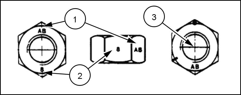
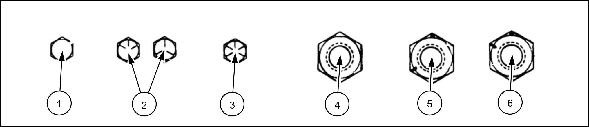
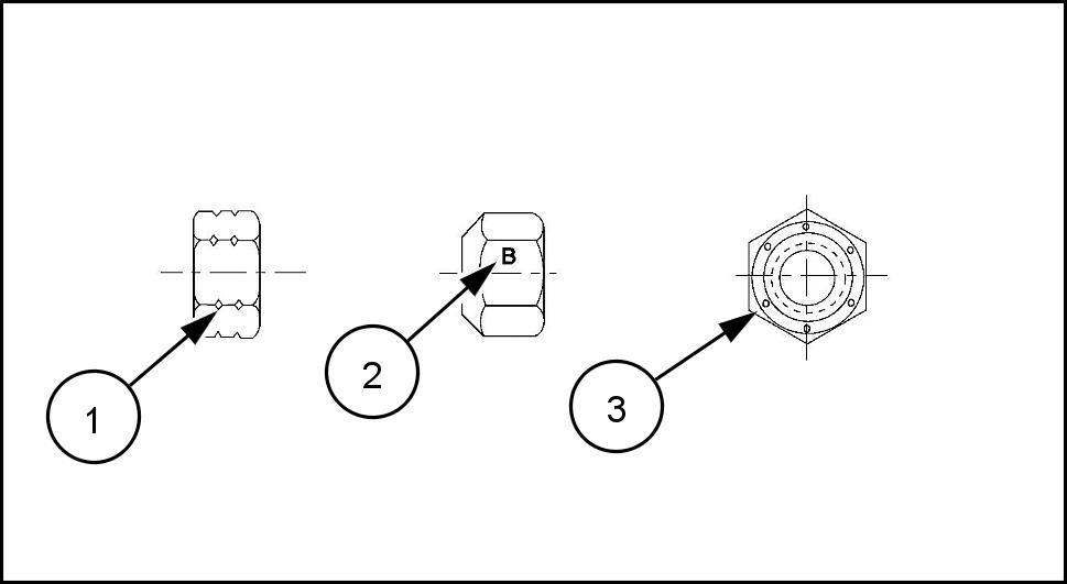
Inch lock nuts, all metal (three optional methods)
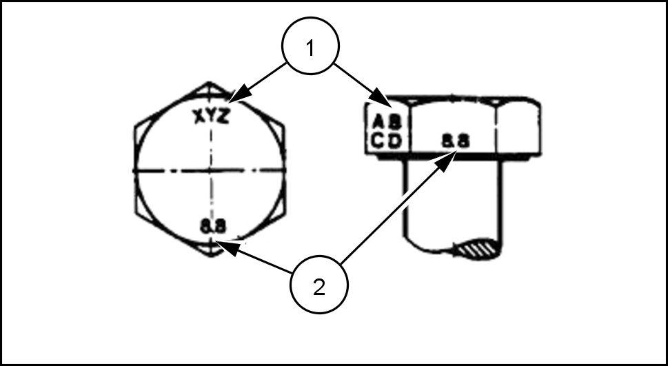
Grade identification Grade
Grade A notches mark marks
Grade B One circumferential notch Letter B Three marks
Grade C T circumferential notches Letter C Six marks
T
orque Standard torque data for hydraulics
Installation adjustable fittings straight thread O - ring bosses
Lubricate the O - ring coating with a light oil
Install the O - ring the groove adjacent the metal backup washer which assembled the extreme end the groove (4) .
Install the fitting into the straight thread boss until the metal backup washer contacts the face the boss (5) .
NOTICE: not over tighten and distort the metal backup washer
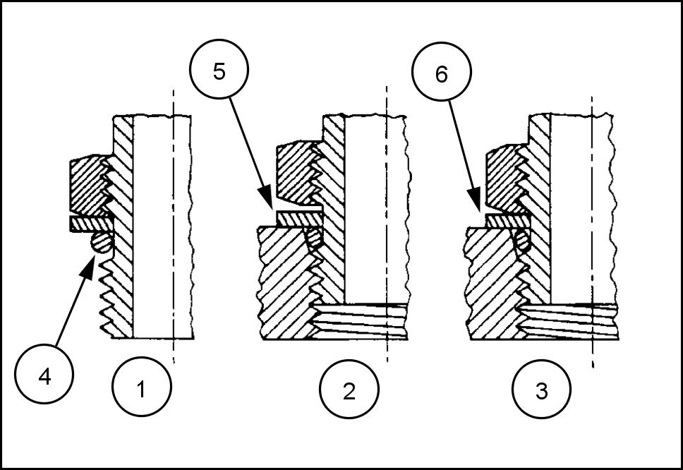
Position the fitting turning out (counterclockwise) a maximum one Holding the pad the fitting with a tighten the lock nut and washer against the face the boss (6) .
Standard torque data for hydraulic tubes and fittings
0.889 ( 0.035 ) The torque specified for 0.889 ( 0.035 ) wall tubes each application ually
Before installing and torquing ° flared clean the face the flare and threads with a clean solvent Loctite cleaner and apply hydraulic sealant L OCTITE ® 569 the ° flare and the
Install fitting and torque specified loosen fitting and retorque

NOTE: If there is no response to click on the link above, please download the PDF document first, and then click on it. Have any questions please