SERVICE MANUAL 7630 / 8030 TIER 3 Tractor Part number 47793462 English April 2017 © 2017 CNH Industrial Latin America LTDA. All Rights Reserved.


[10.001] Engine and crankcase
[10.216] Fuel tanks
[10.250] T urbocharger and lines
[10.254] Intake and exhaust manifolds and muf fler
[10.400] Engine cooling system
Clutch hydraulic release control
10] Clutch and components
ransmission
14] Mechanical transmission
[21.130] Mechanical transmission external controls
[21.140] Mechanical transmission internal components
[21.160] Creeper
[23.202] control
[25.102] Front bevel gear set and dif ferential
[25.108] Final drive hub, steering knuckles, and shafts
Rear axle system
Rear bevel gear set and dif ferential
Planetary and final drives
Power T ake-Of f (PT
[31.104] Rear electro-hydraulic control
14] T rear Power T f (PT
Brakes and controls
[33.120] Mechanical service brakes
10] Parking brake parking lock
Hydraulic systems
[35.000] Hydraulic systems
[35.104] Fixed displacement pump
[35.102] Pump control valves
[35.204] Remote control valves
16] hitch cylinder
Hitches, drawbars, and implement couplings
[37.1 10] Rear hitch
Frames and ballasting
Ballasts and supports
Steering
[41.101] Steering control
[41.200] Hydraulic control components
[41.216] Cylinders
Front wheels
Rear wheels Electrical systems
[55.100] Harnesses and connectors
Engine starting system
[90.100] Engine hood and panels
International symbols
Foreword - Important notice regarding equipment servicing
Foreword - How use and navigate through this manual
Safety rules
Safety rules
Safety rules
Safety rules - Ecology and the environment
Safety rules
T orque - Minimum tightening torques for normal assembly
Basic instructions - Shop and assembly
T orque - Standard torque data for hydraulics
Engine cooling system - Basic instructions
T orque
Fluids and lubricants
a guide the operation the various universal symbols have been utilized the and fuse The symbols are shown below with indication their


All repair and maintenance work listed this manual must carried out only qualified dealership strictly complying with the instructions and whenever the special
Anyone who performs repair and maintenance operations without complying with the procedures provided herein shall responsible for any subsequent
The manufacturer and all the organizations its distribution chain, including - without limitationnational, regional, local reject any responsibility for damages caused parts and / components not approved the facturer , including those used for the servicing repair the product manufactured marketed the manufacturer any case, warranty given attributed the product manufactured marketed the manufacturer case damages caused parts and / components not approved the manufacturer
The manufacturer reserves the right make improvements design and changes specifications any time without notice and without incurring any obligation install them units previously and illustrative material herein are accurate known time publication but are subject change without notice. case refer your NEW HOLLAND Sales and Service
This manual has been produced a new technical information This new system designed deliver technical information electronically through web delivery and paper A coding system called SAP has been developed link the technical information other Product Support functions, e.g., W arranty .
T
echnical information written support the maintenance and service the functions systems a When a customer has a concern their machine usually because a function system their chine not working not working ficiently , not responding correctly their When you refer the technical information this manual resolve that you will find all the information classified using the SAP coding, according the functions systems that machine. Once you have located the technical information for that function you will then find all the electrical hydraulic and sub assemblies for that function Y will also find all the types information that have been written for that function system: the technical data the functional data (how the diagnostic data (fault codes and and the service data install
integrating SAP coding into technical you will able search and retrieve just the right piece technical information you need resolve that concern his This made possible attaching 3 categories each piece technical information during the authoring process.
The first category the the second category the Information T ype and the third category the Product:
• LOCA TION - the component function the machine, that the piece technical information going describe Fuel
• INFORMA TION TYPE - the piece technical information that has been written for a particular component tion the machine Capacity would a type T echnical Data describing the amount fuel held the fuel
• PRODUCT - the model for which the piece technical information written.
Every piece technical information will have those three categories attached Y will able use any nation those categories find the right piece technical information you need resolve that concern their
That information could be:
• the procedure for how remove the cylinder head
• a table specifications for a hydraulic pump
• a fault code
• a troubleshooting table
• a special tool
This manual divided into Sections. Each Section then divided into Chapters. Contents pages are included the beginning the then inside every Section and inside every Chapter alphabetical Index included the end each Chapter Page number references are included for every piece technical information listed the Chapter Contents Chapter
Each Chapter divided into four Information types:
• T echnical Data (specifications) for all the electrical hydraulic assemblies sub -
• Functional Data (how works) for all the mechanical, electrical hydraulic devices, components, assemblies sub -
• Diagnostic Data (fault electrical and hydraulic troubleshooting) for all the electrical hydraulic assemblies sub -
• Service Data (remove install) for all the electrical hydraulic assemblies sub -
Sections are grouped according the main functions a systems the Each Section identified a number The Sections included the manual will depend the type and function the machine that the manual written for . Each Section has a Contents page listed alphabetic / numeric order . This table illustrates which Sections could included a manual for a particular
V ehicles with working arms: skid forage
Seeding, planting, floating, spraying
- Maintenance
Mounted equipment and
X X X X X
- Machine completion and equipment X X X X X
- Engine X X X X
- Main gearbox and drive X X X X
- Clutch X X X
- T ransmission X X X X
- Four wheel drive (4WD) system
- Front axle system
X X X X
X X X X
- Rear axle system X X X X
- Hydrostatic drive X X X X
- Power T ake - f (PT X X
- Brakes and controls X X X X
- Hydraulic systems X X X X
- Pneumatic system X X X X
- drawbars and implement couplings
- Frames and ballasting
- Steering
X X
X X X X
X X X
- Wheels X X X X
- Steering clutches
- T racks and track suspension X X X
- Cab climate control X X X X
- Electrical systems X X X X X
- Grape harvester shaking
- Attachments / headers X
- Product feeding X
- Metering system
- Pressing - Bale formation
- Chemical applicators
- Chopping
- Threshing
- T ying / W rapping / T wisting
- Bale wagons
- Ejection
- Lubrication system
- Separation
- Residue handling
- Cleaning
- Soil preparation / Finishing
- Secondary cleaning / Destemmer
- Seeding
- Spraying
- Planting
- Crop storage / Unloading
- Front loader and bucket
- T elescopic single arm
- dippers and buckets
- Dozer blade and arm
- Accessories
- T ools
- bodywork and decals
X X X X
X
X
X
X
X X X X
X X X X
X X X
Chapters
Each Chapter identified a number e.g. Engine - Engine and crankcase10.001. The first number identical the Section number Chapter inside Section The second number representative the Chapter contained within the CONTENTS
The Chapter Contents lists all the technical data functional data (how diagnostic data (fault codes and troubleshooting), and service data (remove, install, adjust, etc.), that have been written that Chapter for that function system the
The Chapter Index lists alphabetical order all the types information (called information units) that have been written that Chapter for that function system the
Each chapter composed information units. Each information unit has the SAP code shown parentheses. This indicates the function and type information that information Each information unit has a page reference within that Chapter The information units provide a quick and easy way find just the right piece technical information you are looking for
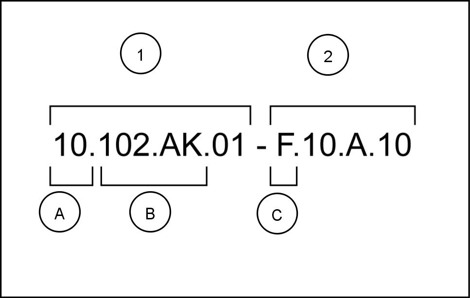
Example information unit Engine block cover - Front – Remove - F
SAP code classification Engine Pan and covers Engine block cover Front Service data Remove
1
Navigate the correct information unit you are searching for identifying the function and information type from the SAP
• (1) Location and (2) Information type.
• (A) corresponds the sections the service (B) corresponds the chapters the service manual. After (B) there may some additional information. this case shows “.01”, which represents the block cover These options may front / rear , left / hydraulic / mechanical (C) corresponds the type information listed the chapter contents: T echnical Functional (A) and (B) are also shown the page numbering the page footer . THE REST THE CODING NOT LISTED ALPHANUMERIC ORDER THIS
• Y will find a table contents the beginning and end each section and chapter Y will find alphabetical index the end each chapter
• referring (A) , (B) and (C) the you can follow the contents index (page numbers) and quickly find the information you are looking for .
The page header will contain the following references:
• Section and Chapter description
The page footer will contain the following references:
• Publication number for that
• V ersion reference for that publication.
• Publication date
• Section, chapter , and page reference e.g. 10.102 / 9
informed and notify personnel the laws force regulating safety , and provide documentation available for
• Keep working areas clean
• Ensure that working areas are provided with emergency They must clearly visible and always contain adequate sanitary
• Fire extinguishers must properly identified and always clear Their ficiency must checked a regular basis and personnel must trained proper interventions and priorities.
• Keep all emergency exits free obstructions and clearly
• Smoking working areas subject fire danger must strictly prohibited.
• W ear suitable work attire and safety glasses with jewelry such rings and chains when working close engines and equipment
• W ear safety gloves and goggles when performing the following operations:
• T opping f changing lubrication
• Using compressed air liquids a pressure greater than 2 bar ( psi )
• W ear a safety helmet when working close hanging loads equipment working head
• Always wear safety shoes and fitting
• Use protection cream for
• Change wet clothes soon
• the presence voltages exceeding – V , verify the ficiency the ground and mass electrical Ensure that hands and feet are dry and use isolating foot W orkers should properly trained work with electricity .
• not smoke start open flame close batteries and any fuel
• Place soiled rags with diesel fuel solvents specially provided anti - fire
• not use any tool equipment for any use other than what was originally intended for Serious injury may occur
• running engine make sure there a suf ficient exhaust fan use eliminate exhaust
• Never open the filler cap the cooling system when the engine High temperature liquid operating pressure could result serious danger and risk W ait until the temperature decreases under ( 122 )
• Never add coolant overheated engine and use only appropriate
• Always work when the engine turned Certain circumstances require maintenance a running aware all the risks involved with such operation.
• Always use adequate and safe containers for engine fluids and used
• Keep engine clean any spilled fluids such oil, diesel fuel, and chemical solvents.
• Use solvents detergents during maintenance may emit toxic Always keep working areas W ear a safety mask necessary
• not leave soiled rags that may contain any flammable substances close the
• Always use caution when starting engine after any work has been prepared cut f intake air case engine runaway
• Never disconnect the batteries while the engine
• Disconnect the batteries prior performing any work the equipment.
• Disconnect the batteries place a load them with a load tester
• After any work verify that the battery clamp polarity correct and that the clamps are tight and safe from accidental short circuit and
• Before disconnecting any pipelines fuel verify that all pressure has been T ake all necessary precautions bleeding and draining residual Always wear the proper safety
• not alter the lengths any wires.
• not connect any electronic service tool the engine electrical equipment unless specifically approved NEW HOLLAND
• not modify the fuel system hydraulic system unless approved NEW HOLLAND Any unauthorized cation will compromise warranty assistance and may fect engine operation and life
For engine equipped with electronic control unit
• not weld any part the equipment without removing the control
• Remove the case work requiring heating over ( 176 )
• not paint the components and the electronic
• not alter any data filed the electronic control unit driving the Any manipulation alteration electronic components will void engine warranty assistance and may fect the correct working order and life span the engine.
• Respect the environment should primary importance. T ake all necessary precautions ensure safety and
• Inform the personnel the laws regarding the dispensing used engine
• Handle batteries with storing them a well ventilated environment and within anti - acid container
General Aspects
• Strictly follow repair and maintenance procedures.
• not wear wrist jewelry , unbuttoned items unsecured clothing like torn open jackets shirts with open zippers that could get caught moving Use proved safety such anti - slip footwear , protective
• W ear safety goggles with side shields when cleaning parts using compressed air
• W orn damaged cables and chains are not not use these elements lifting towing
• Use regulation safety such approved eye and special footwear whenever you are welding. All individuals near the welding process must use regulation eye protection. Never look the welding arc without using suitable eye
• Never perform any repairs the machine there someone the operator except when the person a qualified operator who helping with the service
• Never operate the machine use accessories from a place other than the operator seat next the machine when operating the fender switches.
• Never perform any operations the machine with the engine except when specifically instructed so. Shut down the engine and release all the pressure from the hydraulic circuits before removing covers, cases,
• Y must conduct all repair and maintenance operations with the utmost care and
• Disconnect the batteries and put warning labels all the controls warn that the machine being Lock the machine and all the equipment that you
• Never check fill the fuel tank batteries use starting fluid when you are smoking near a naked because these fluids are
• The fuel filling gun must remain contact with the filler neck. Maintain the contact until the fuel stops flowing into the tank order avoid sparks caused static electricity build -
• T o transport a faulty use a trailer a low loader platform trolley ,
• T o load and unload the machine from the mode choose a flat area that fers firm support for the wheels the truck trailer Securely fasten the machine the platform the trailer accordance with the transporter ’ s
• Always use hoist mechanisms with appropriate capacity for lifting moving heavy
• Chains must always securely fastened. The fastening device must have suf ficient capacity support the tended prohibited for bystanders near the fastening
• The work area must always clean and dry . Clean immediately any water oil spilled.
• Never use other flammable liquids for Use only non - toxic
• not allow cloths soaked with oil grease accumulate because they can cause a fire Always keep these cloths a metal container
• Never start the engine enclosed spaces that are not equipped with a suitable exhaust system gas - extraction
• Never bring your body , fingers close fans rotating
• Always loosen the radiator cap slowly before removing order dissipate the system Y must top the coolant with the engine
• not fill the fuel tank when the engine running.
• Never adjust the fuel injection pump when the machine

NOTE: If there is no response to click on the link above, please download the PDF document first, and then click on it. Have any questions please