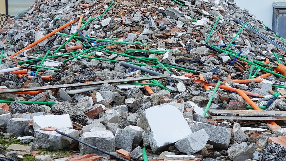
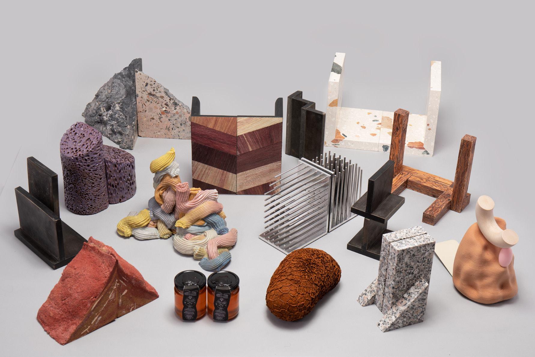
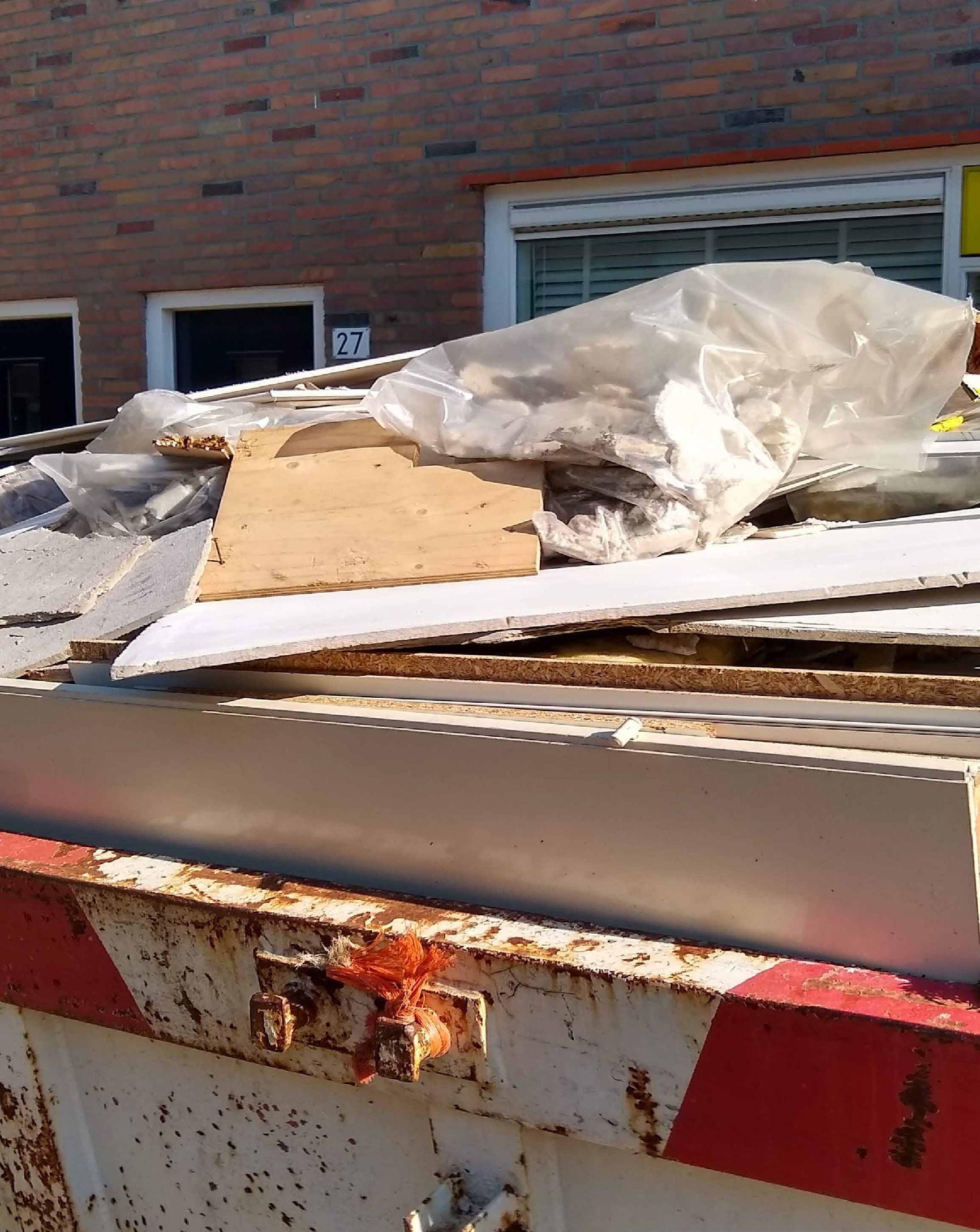
WASTE MATERIALS
CIRCULAR ECONOMY
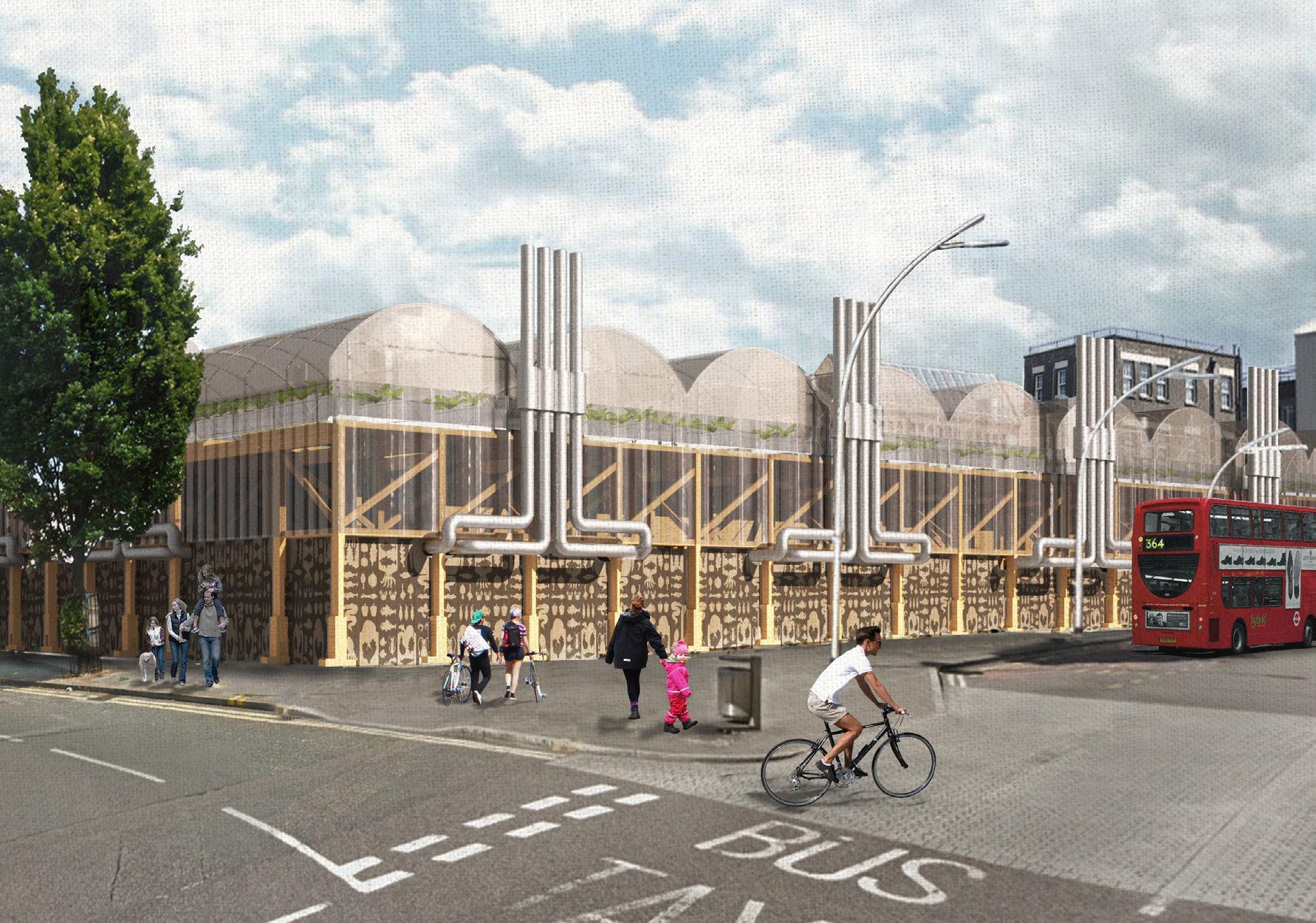
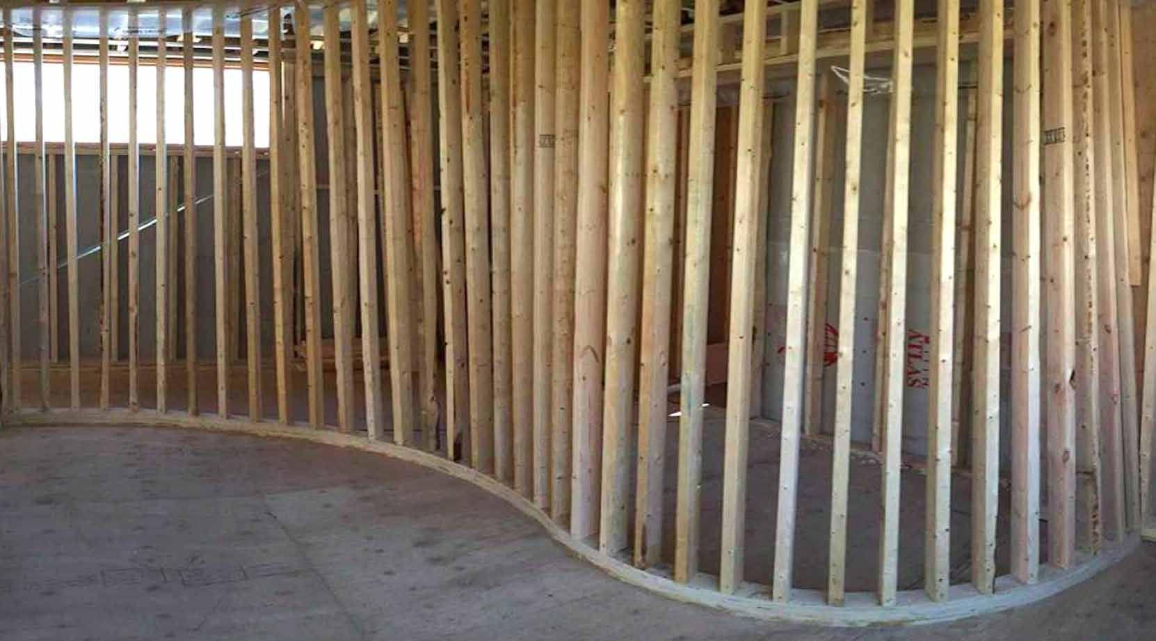
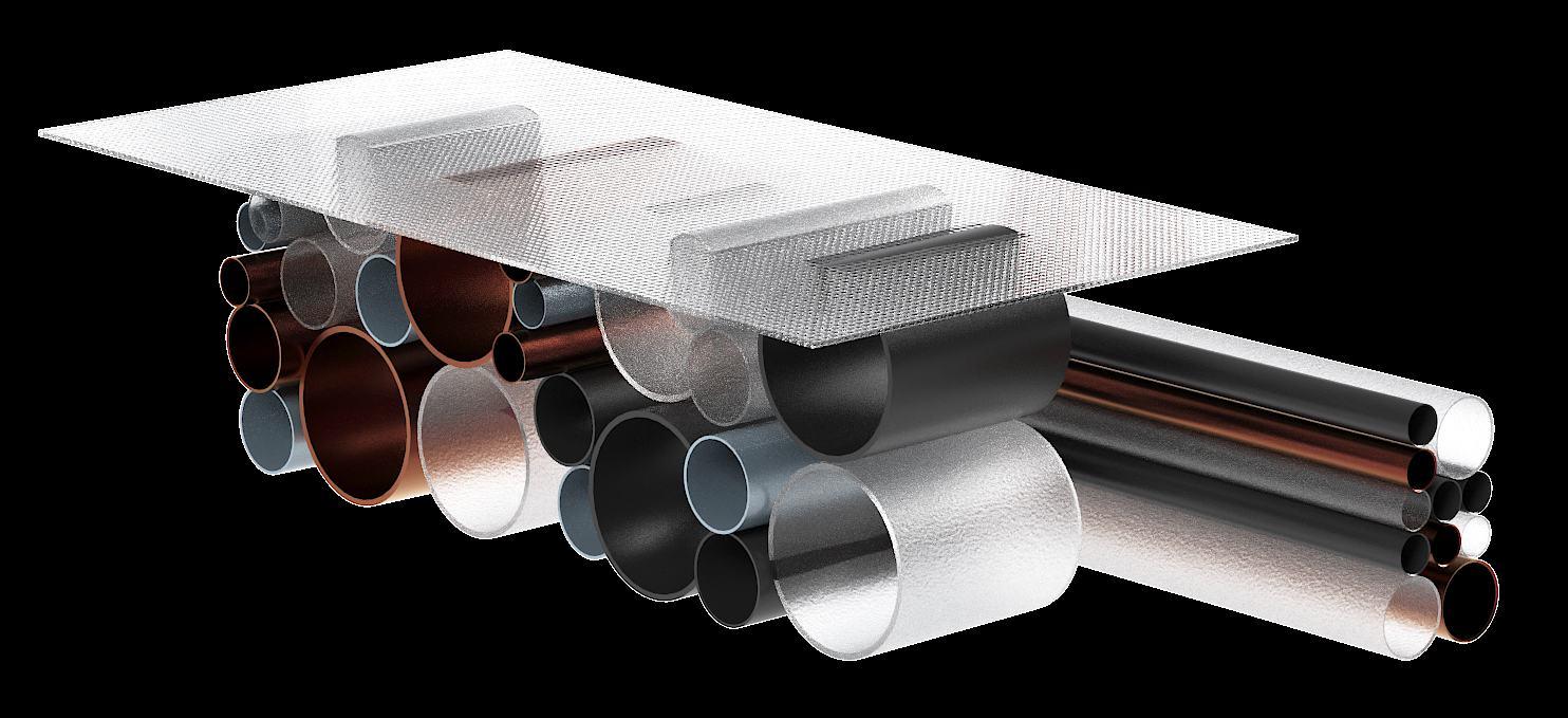
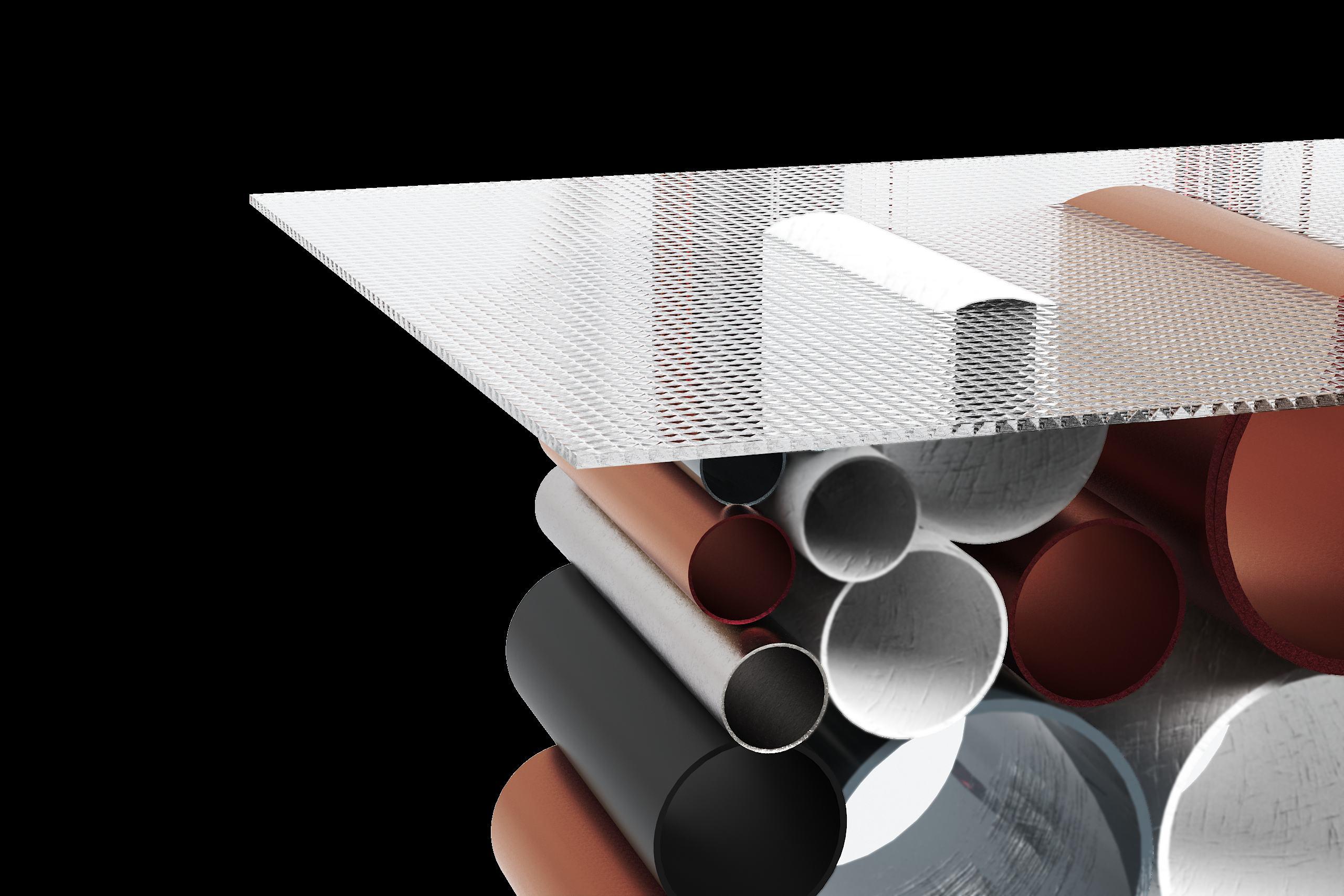
WHY PIPES?
WORKFLOW
PROBLEM STATEMENT
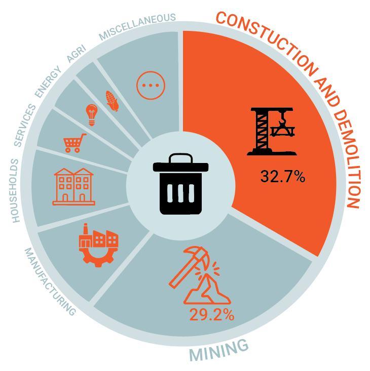
SCALE OF WASTED MATERIALS
The estimated amount of construction and demolition waste generated globally each year. This is expected to be 2.2 billion tons by 2025.
1.3
BILLION
60% of all UK waste comes from the construction industry
ENVIRONMENTAL IMPACT OF WASTE MATERIALS
Degraded Environment: pollution from hazardous construction materials
Traditional construction practices often leave behind hazardous materials that contaminate soil and water, contributing to environmental degradation. Without proper reuse or safe disposal, these materials pollute ecosystems and damage the earth.
Human Health Issues: airborne dust and toxic substances
Construction and demolition sites release fine dust, mold, and toxic substances that pose serious respiratory and health risks to workers and nearby communities. A lack of containment and reuse strategies worsens exposure.
Economic Loss: wasted resources
+ lack of circular economy
Discarding usable construction materials leads to significant financial waste. When materials aren’t recirculated through a circular economy model, valuable resources, labor, energy, and materials are lost.
APPLICATIONS OF CIRCULAR ECONOMY
How can we implement circular economy principles?
Not downcycling: we focus on materials like reusing pipes in structural designs, retaining value and reducing the demand for new materials.
Modular & Reconfigurable Design:
By using 3D-printed joints and a modular assembly system, HoloLab enables structures that can be disassembled or reconfigured.
Digital workflow:
Matches material inventory with design needs. By using environmental analysis and structural optimization, each piece of reused material is placed efficiently CIRCULARIZE
TRADITIONAL DESIGN PROCESS
The traditional architectural workflow follows a linear sequence:
starting from a design task and location selection, moving through environmental and user analyses, followed by concept development, detailed design, and finally construction. Each phase builds sequentially on the last, often resulting in rigid outcomes with limited feedback loops or material reuse strategies.
TRADITIONAL
HOLOLAB DESIGN PROCESS
The HoloLab design process reimagines the workflow:
By embedding circular economy principles, beginning with waste material identification, it feeds into a material database that informs a dynamic, flexible design system. The design process incorporates location, geometry, and user preferences, resulting in a modular product that anticipates future deconstruction and reuse closing the material loop.
HOLOLAB
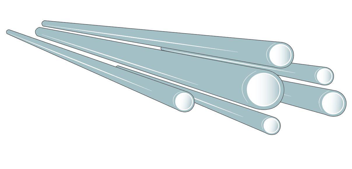
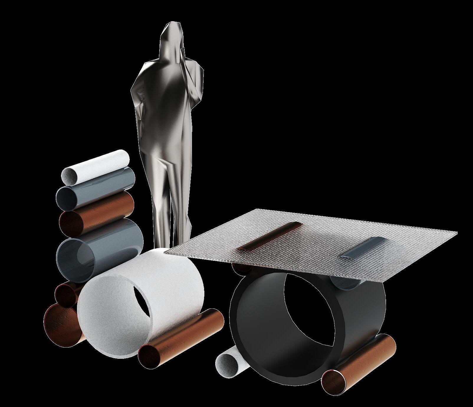
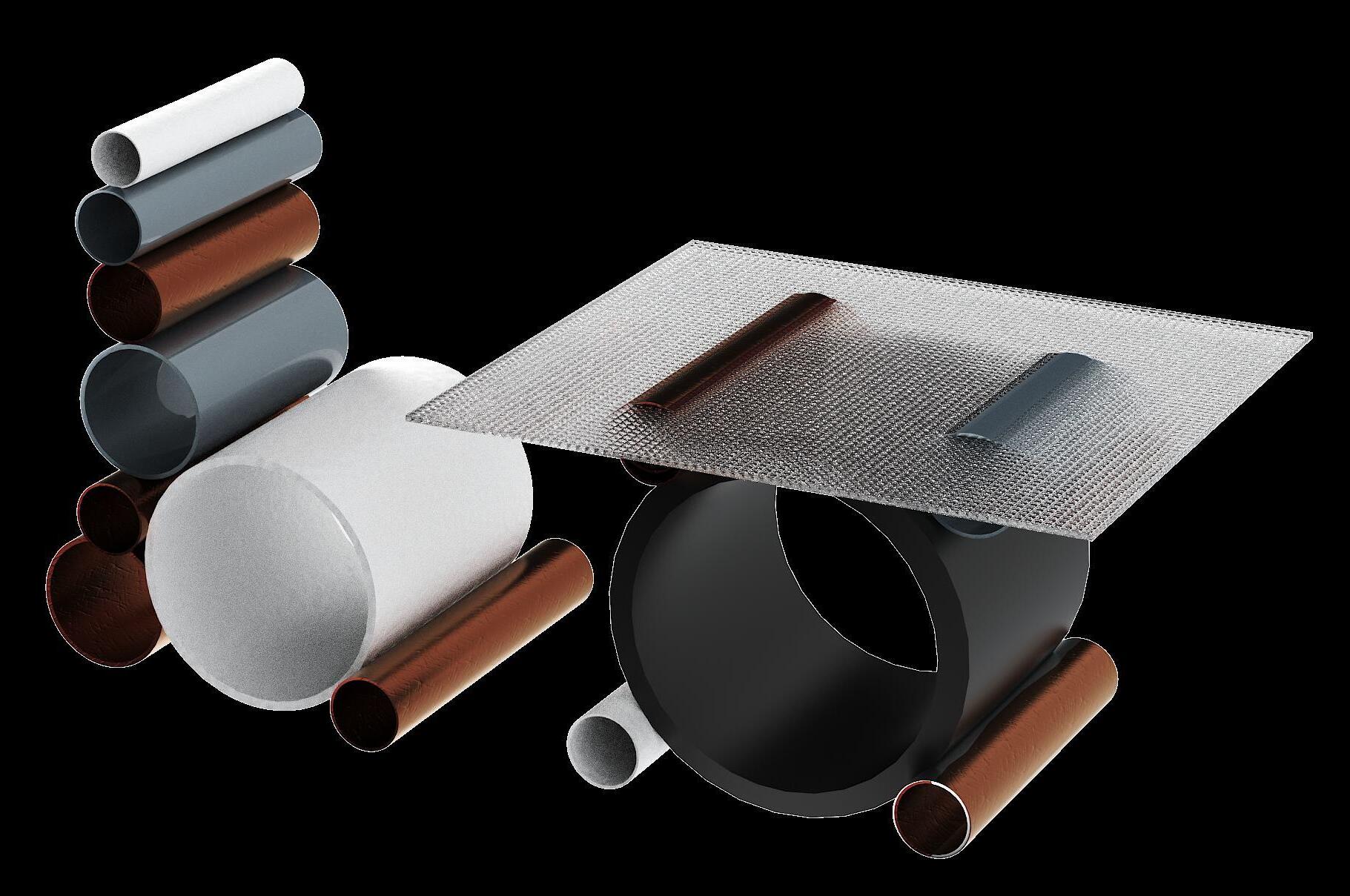
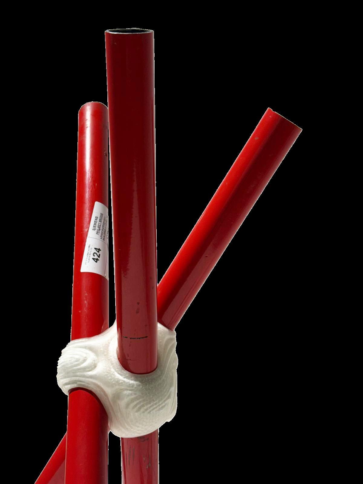
WHY PIPES?
Versatile
Suitable for various applications.
Durable Strong and long lasting, ideal for reuse.
Material Variety
Metal, plastic, composite, and concrete, many of which are hard to recycle.
PIPE LIFECYCLE
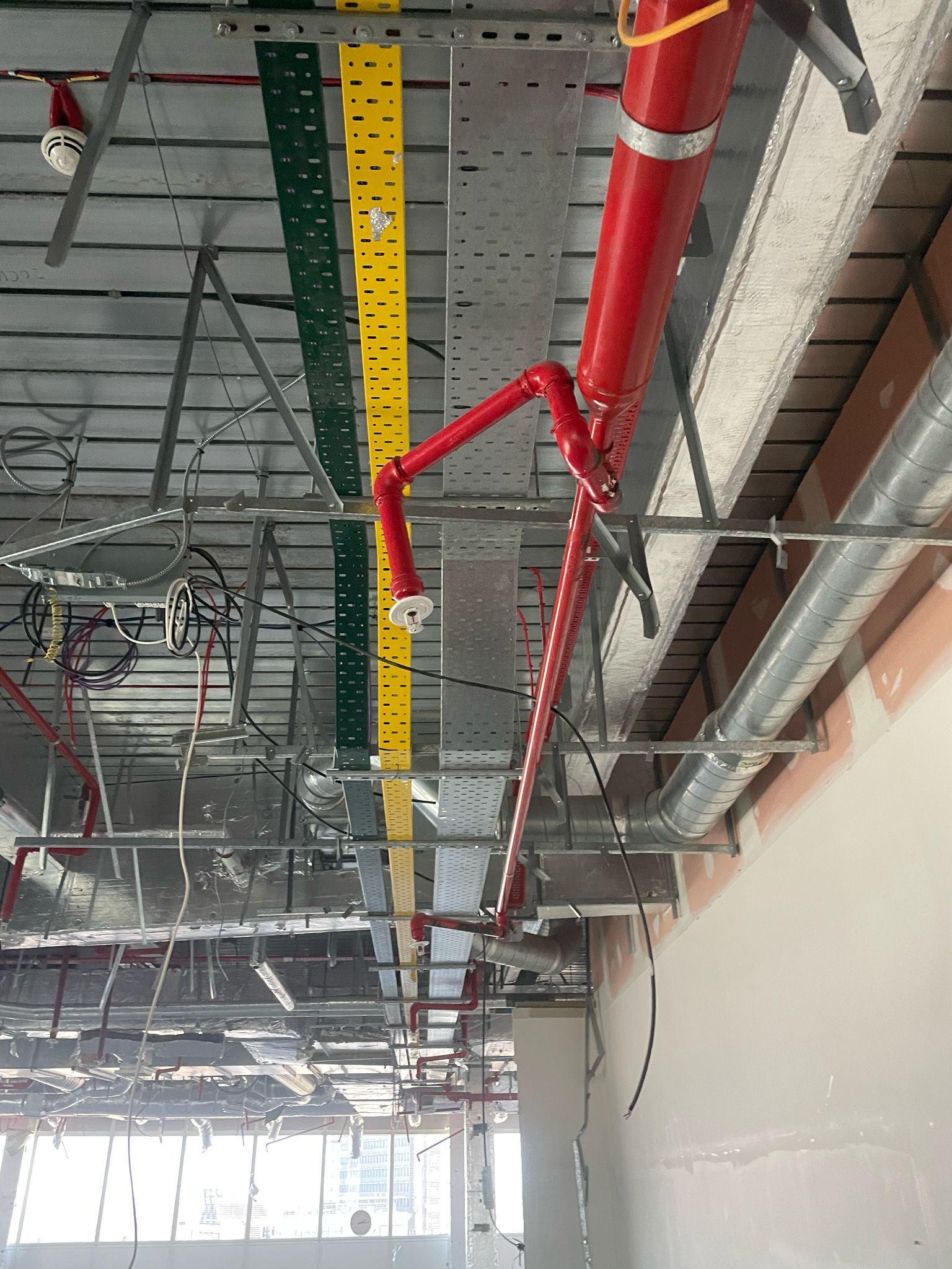
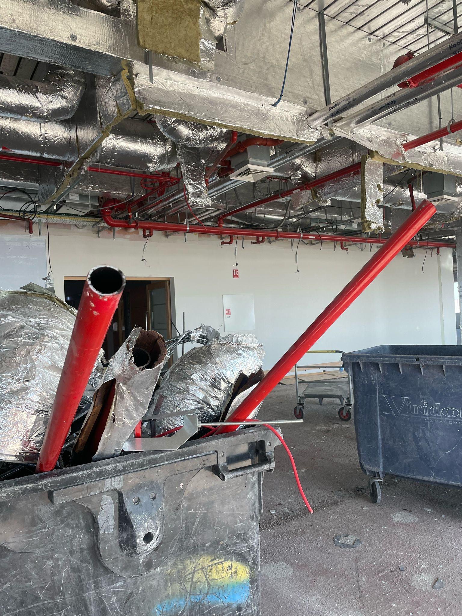
Discarded from construction:
pipes ranging from metal to plastic and composite are typically destined for landfill despite retaining structural integrity. removed during demolition or renovation
The system tailored to fit varying sizes and materials. This approach allows for flexible assembly, easy disassembly repurposes them using 3D-printed joints
The result is a sustainable construction method that maximizes material lifespan and minimizes waste. static waste into dynamic structural designs
HOLOLAB USERS
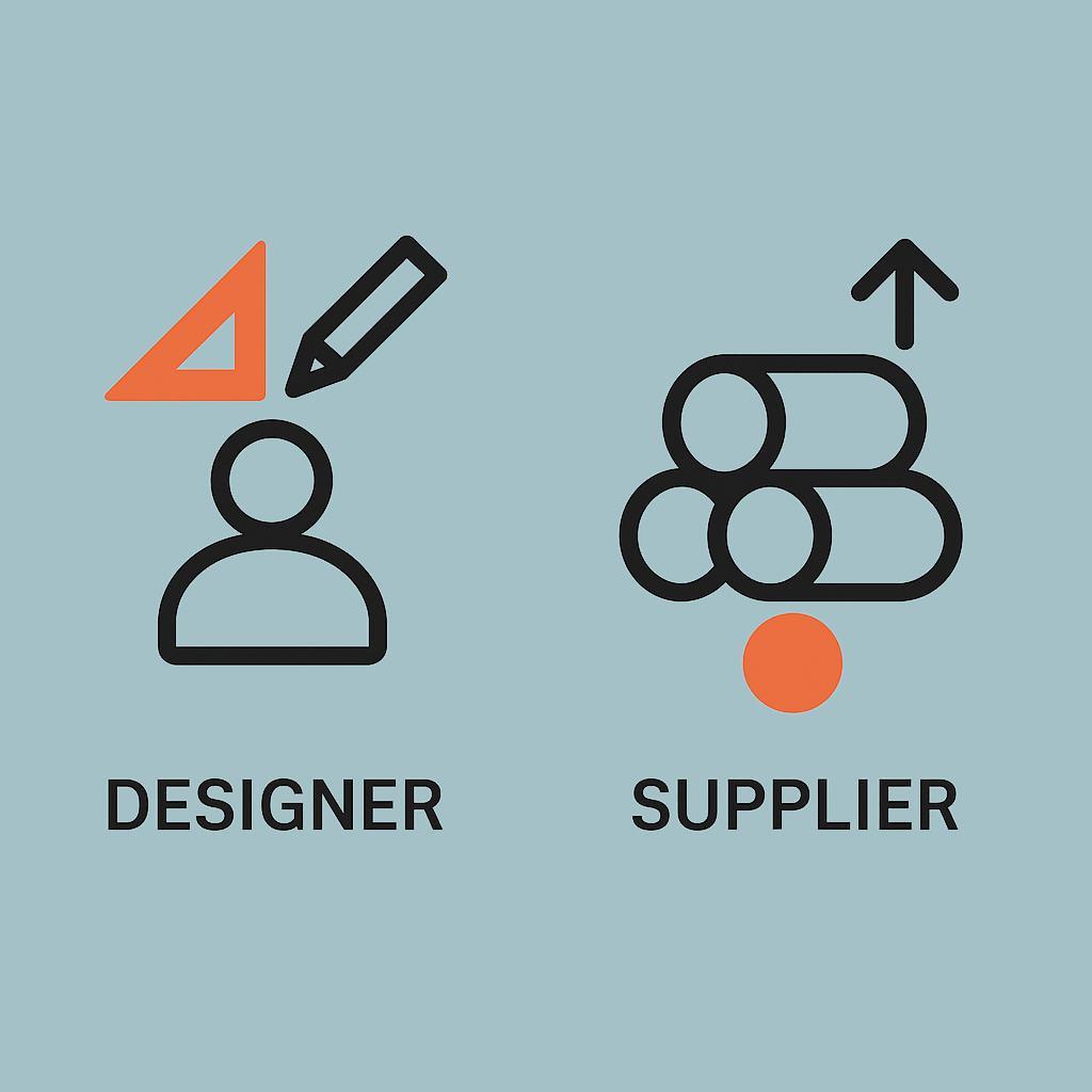
HoloLab bridges design and material supply empowering designers to creatively integrate reclaimed resources and suppliers to efficiently index and connect those materials to projects. The orange highlighted text draws attention to . the platform’s main value propositions for each user group
DESIGNER
Anyone wit a Device
Arc itects
Students
Community Organizers
Urban Planners
Sustainability Researc ers
USES: Exp ore Improve for new R Reduces Demand Materials etrofit Options
Energy Efficiency
Flexible Prioritization
SUPPLIER
Demolition Contractor
Material Recovery Facilities
Construction Companies
Municipal Waste Programs
Audited Materials Networks
USES:
Upload & ndex Materials
Material Matching
Standardized Tracking Comp ex Databa e
PROBLEM
STATEMENT
The construction and demolition industry is the largest contributor to waste in the UK, generating over 60 million tonnes of waste annually, according to the UK Government (Department for Environment Food and Rural Affairs).
This includes valuable materials, including discarded , which are often despite their structural reuse potential.
pipes underutilized
“UK Statistics on Waste.” Accessed 05 Mar. 2025.
The lack of effective systems to categorize and repurpose these materials into adaptable architectural components contributes to waste accumulation and limits sustainable building innovation.
CIRCULAR ECONOMY
MATERIALS RELATED WORK
CIRCULARITY PRECEDENTS
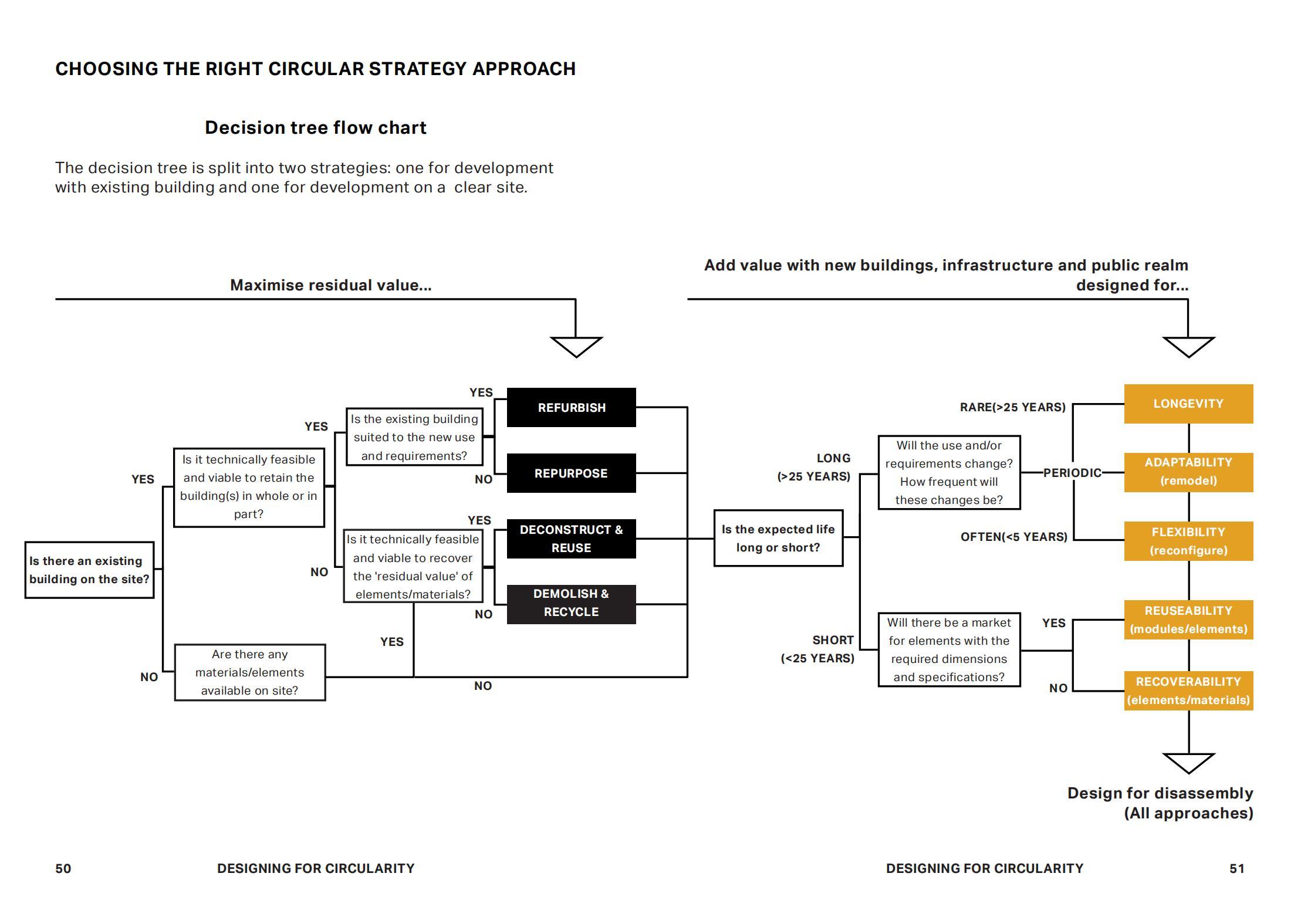
DESIGN FOR A CIRCULAR ECONOMY | LONDON AUTHORITY
Published by the UK’s Greater London Authority, this research explores how circular principles can reshape the construction industry. It promotes modular design, adaptable components, and material passports to enable reuse and reduce waste. By emphasizing early-stage planning and digital tracking, the report provides a practical framework for integrating circularity across the entire building lifecycle.
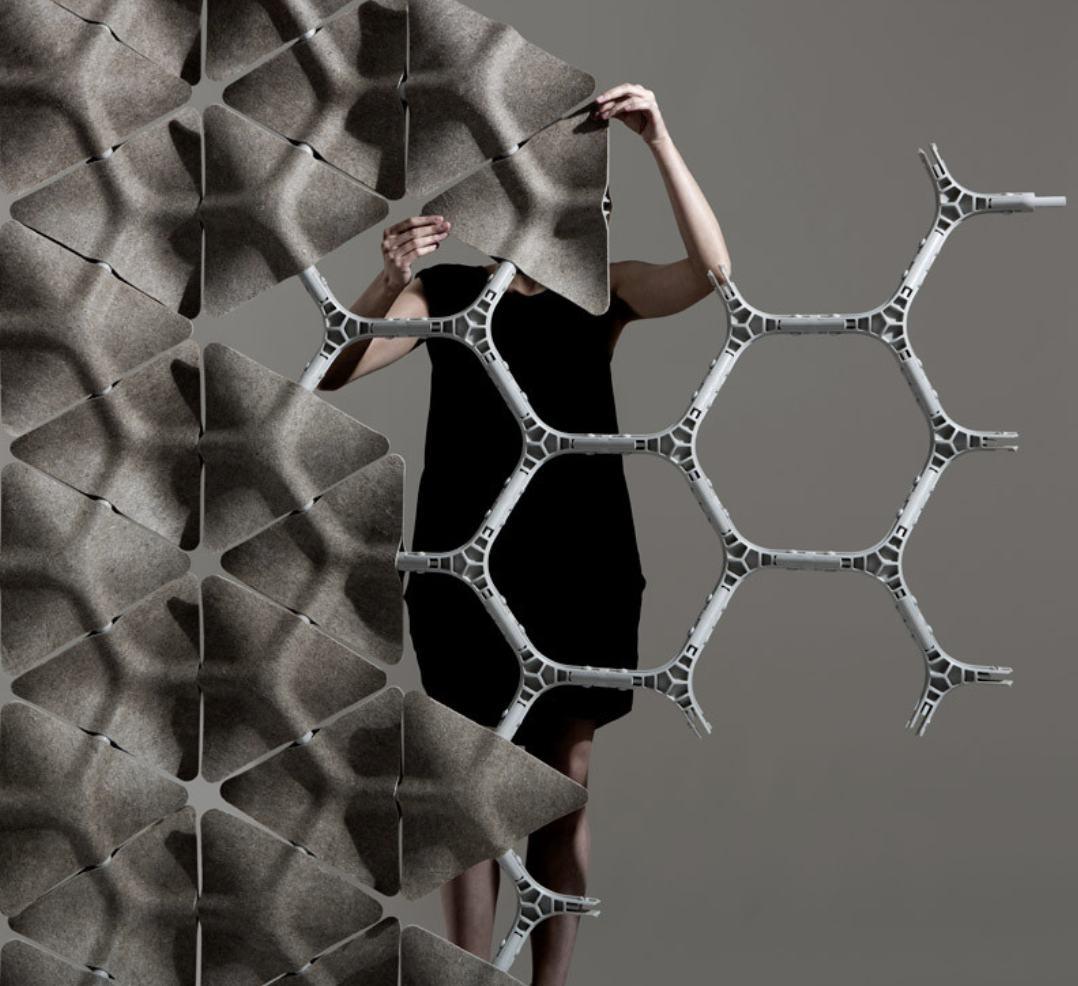
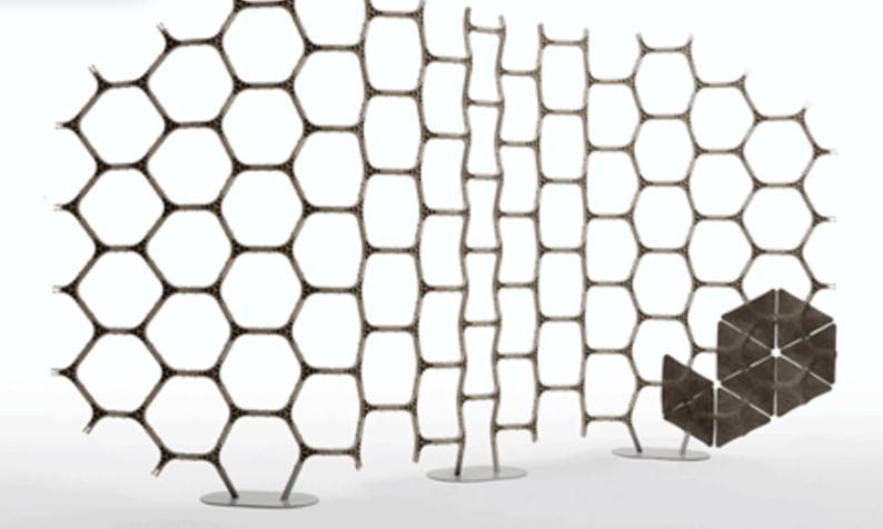
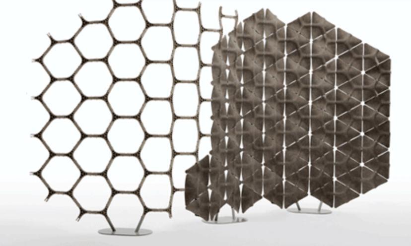
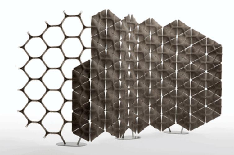
The Scale project by LAYER embodies circular economy principles through its modular, reconfigurable wall system made entirely from recycled materials. Each panel is crafted from recycled PLA derived from corn starch, and connects using an intuitive locking mechanism that allows for easy assembly, disassembly, and reuse without much waste.
SCALE by LAYER
CIRCULARITY PRECEDENTS
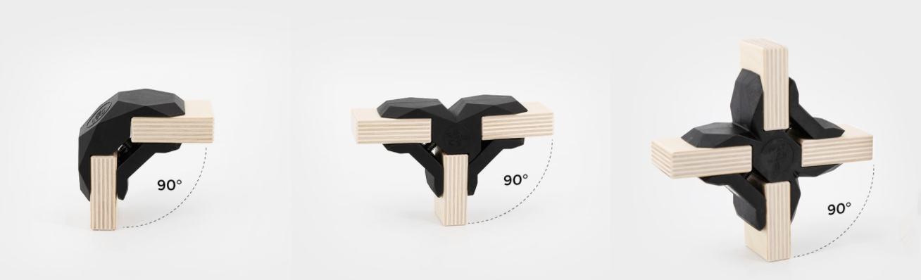
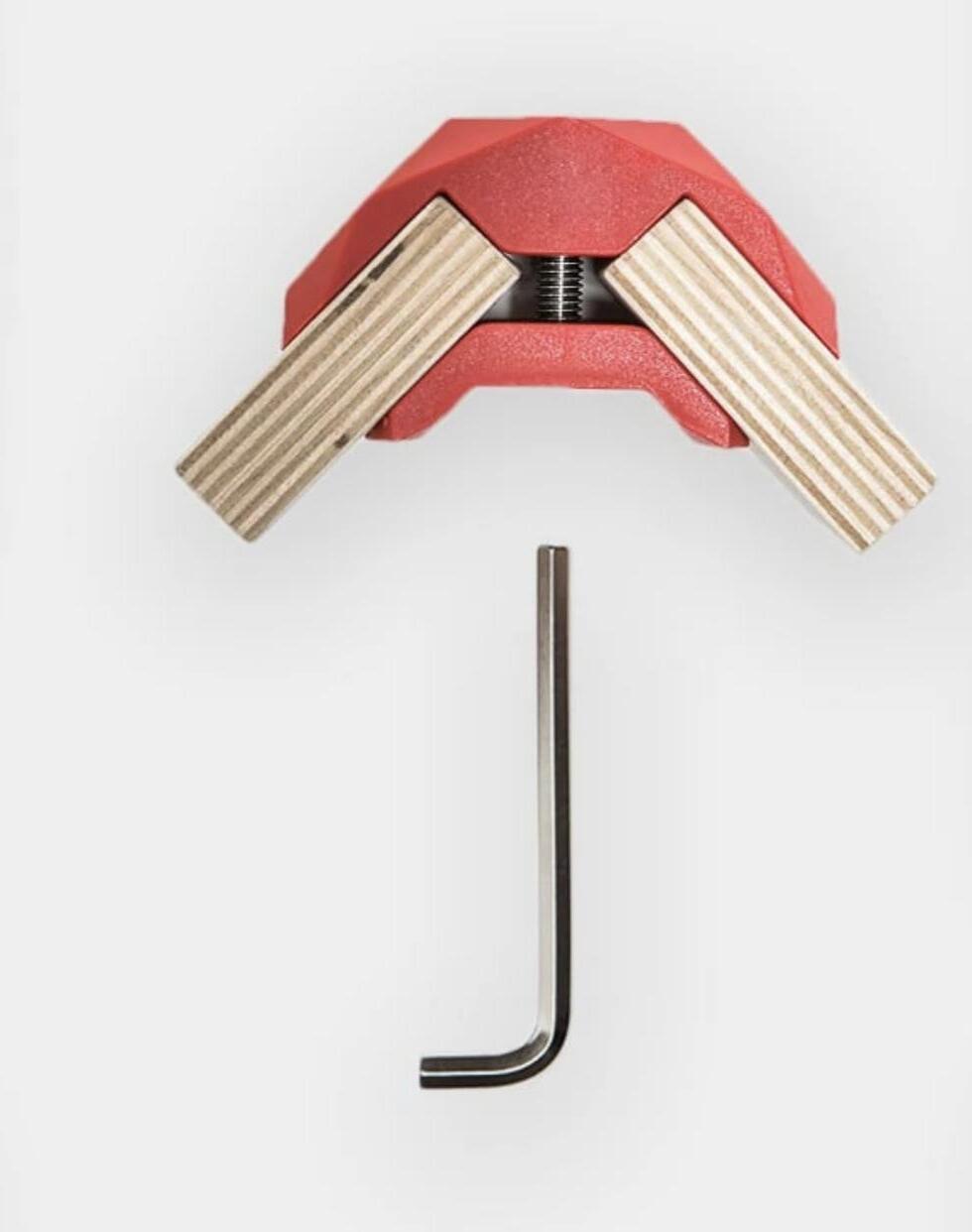
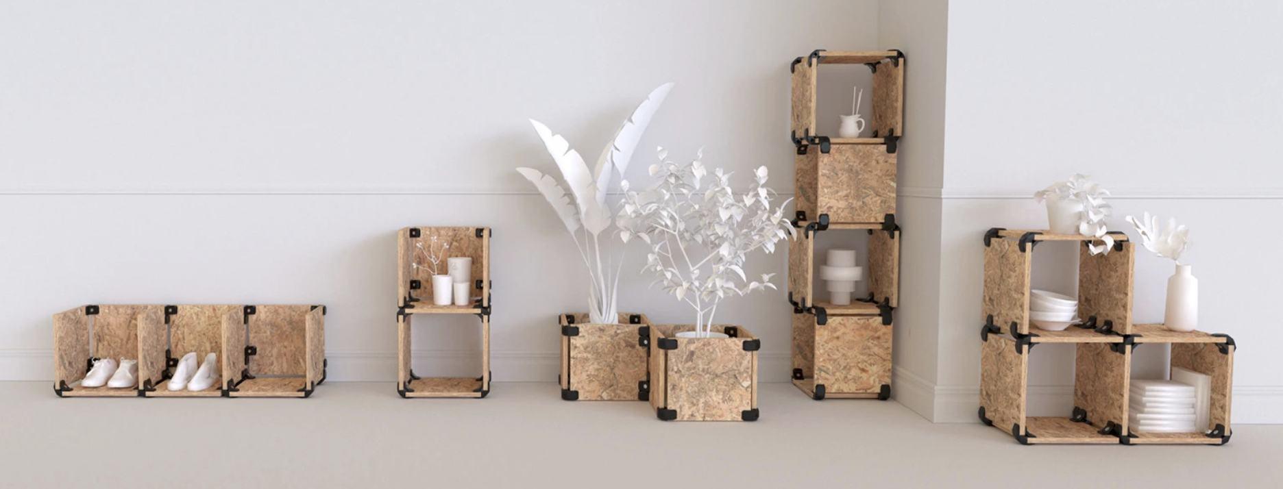
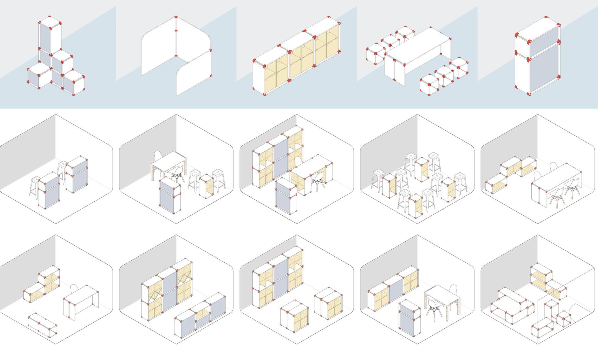
By using durable connectors that join recycled wooden panels without the need for screws or tools, PlayWood allows users to easily assemble, disassemble, and reconfigure furniture to suit evolving needs. This plugand-play approach extends product life, reduces waste, and empowers users to participate in a more sustainable consumption model.
SECURING HEALTHY CIRCULAR FLOWS | TU DELFT
This study by Bob Geldmans from TU Delft explores how non-structural partitions in housing can support circularity. It proposes flexible, modular infill systems using reversible materials, balancing reuse potential with user well-being. The research highlights design strategies that enable adaptability and healthier material cycles in everyday architecture.
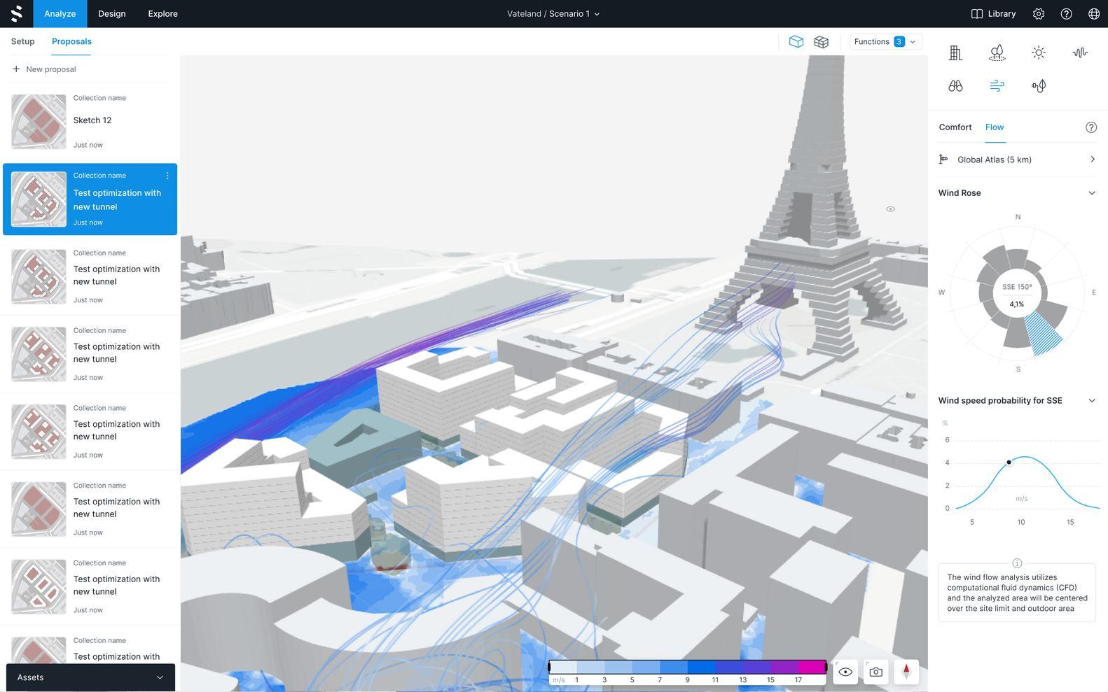
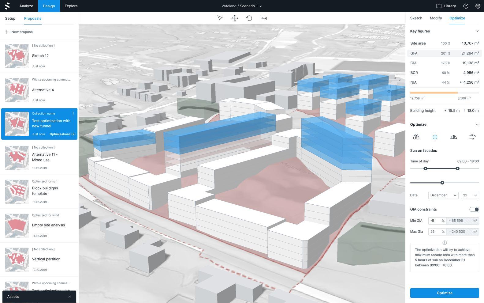
Spacemaker AI is a cloud-based artificial intelligence-assisted design platform developed by a Norwegian startup focusing on decision optimization in the early stages of architectural and urban design. Spacemaker's analytics enable teams to make data-driven decisions in the early stages of a project, improving design efficiency and spatial quality while shortening traditional design timelines.
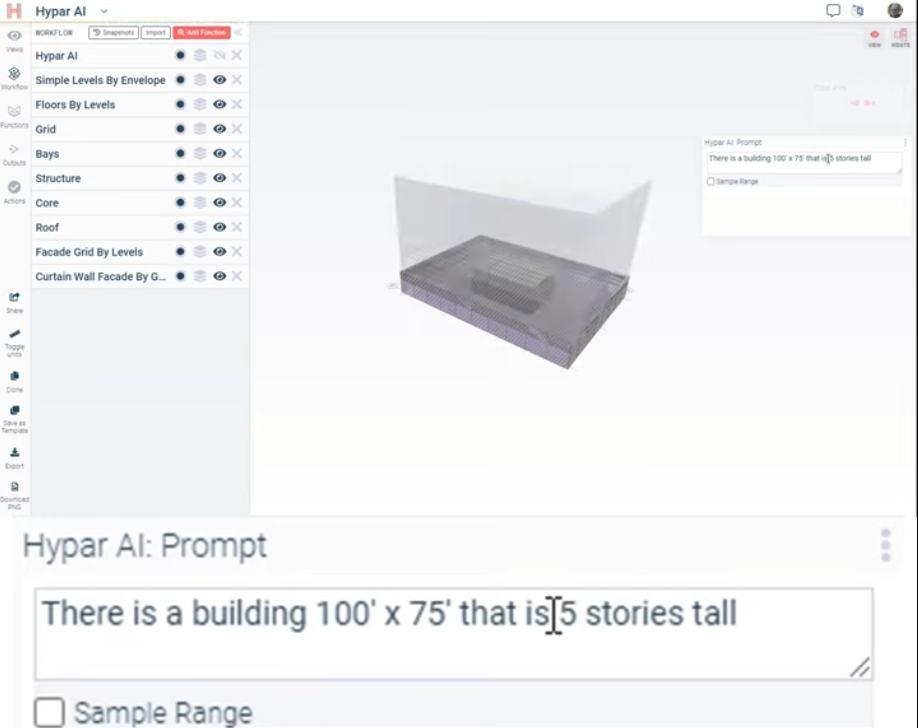
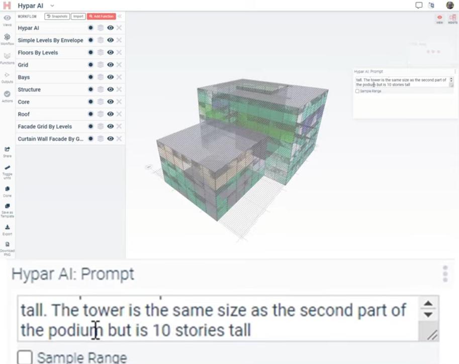
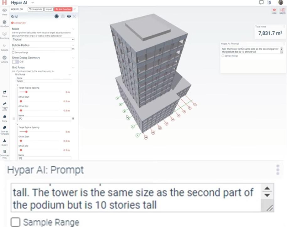
Hypar is a cloud-based building design automation platform that quickly generates spatial layouts and building models through modular functions. Users can write or call existing functions to quickly generate spatial layouts, structural systems and other architectural models, automating the process from architectural program import, spatial partitioning to layout generation. Hypar emphasizes the digitization and automation of the design process, driving the construction industry in an efficient way.
PLATFORM PRECEDENTS
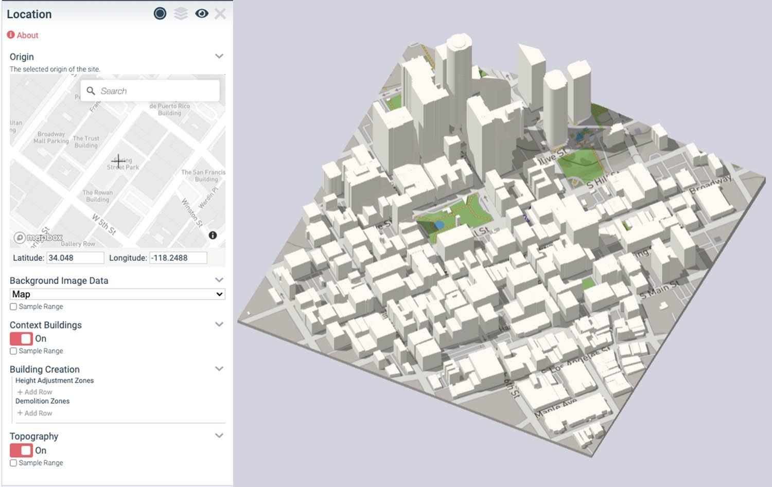
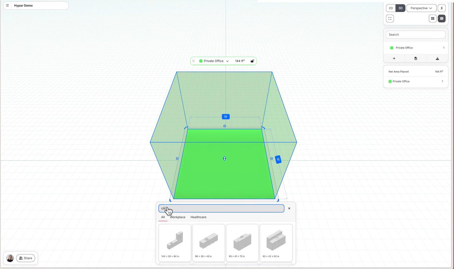
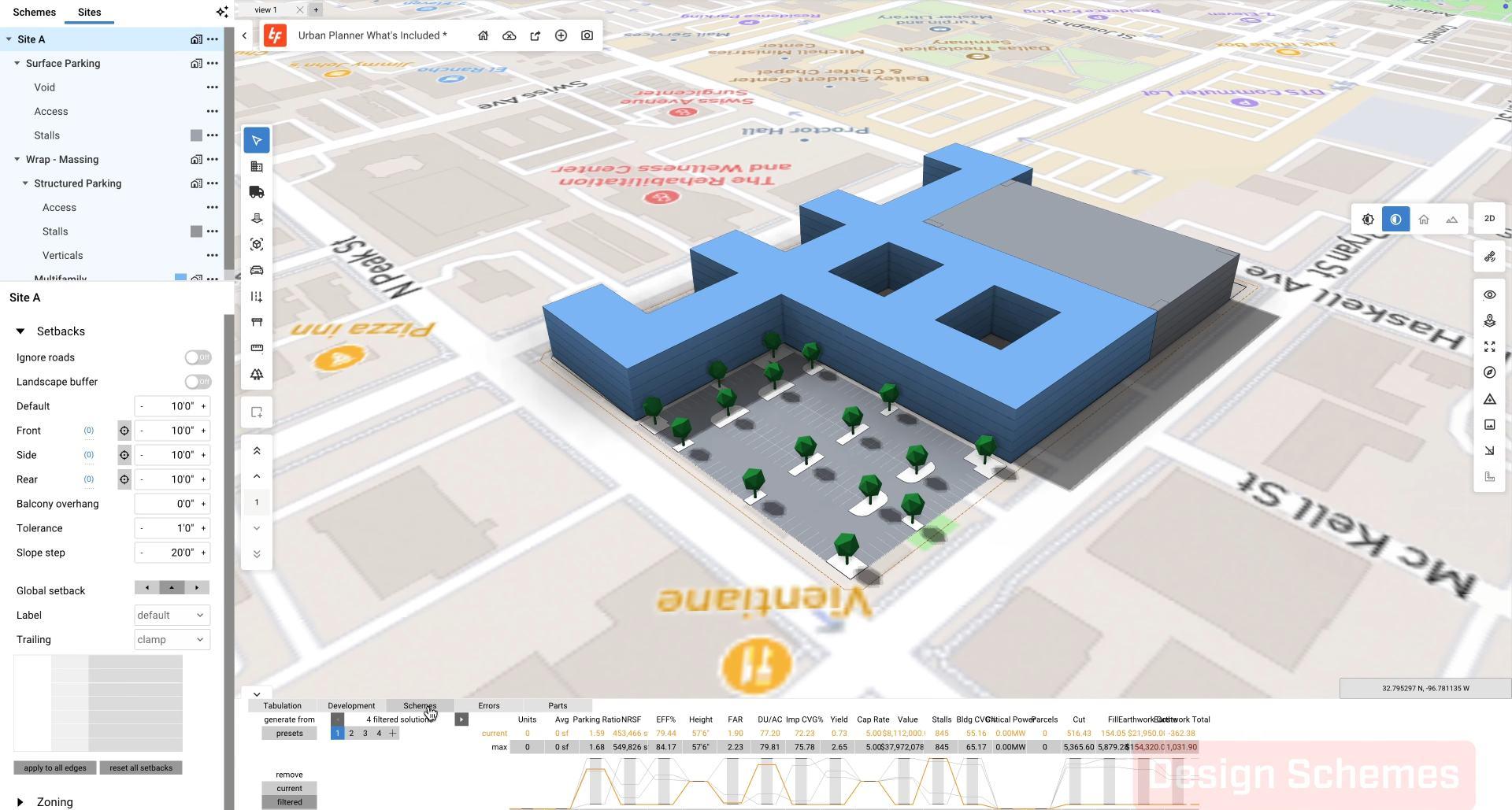
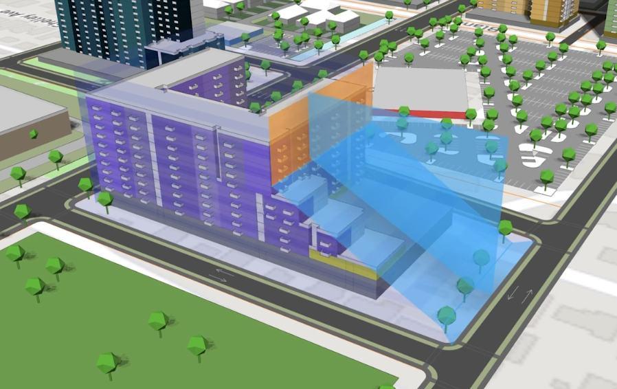
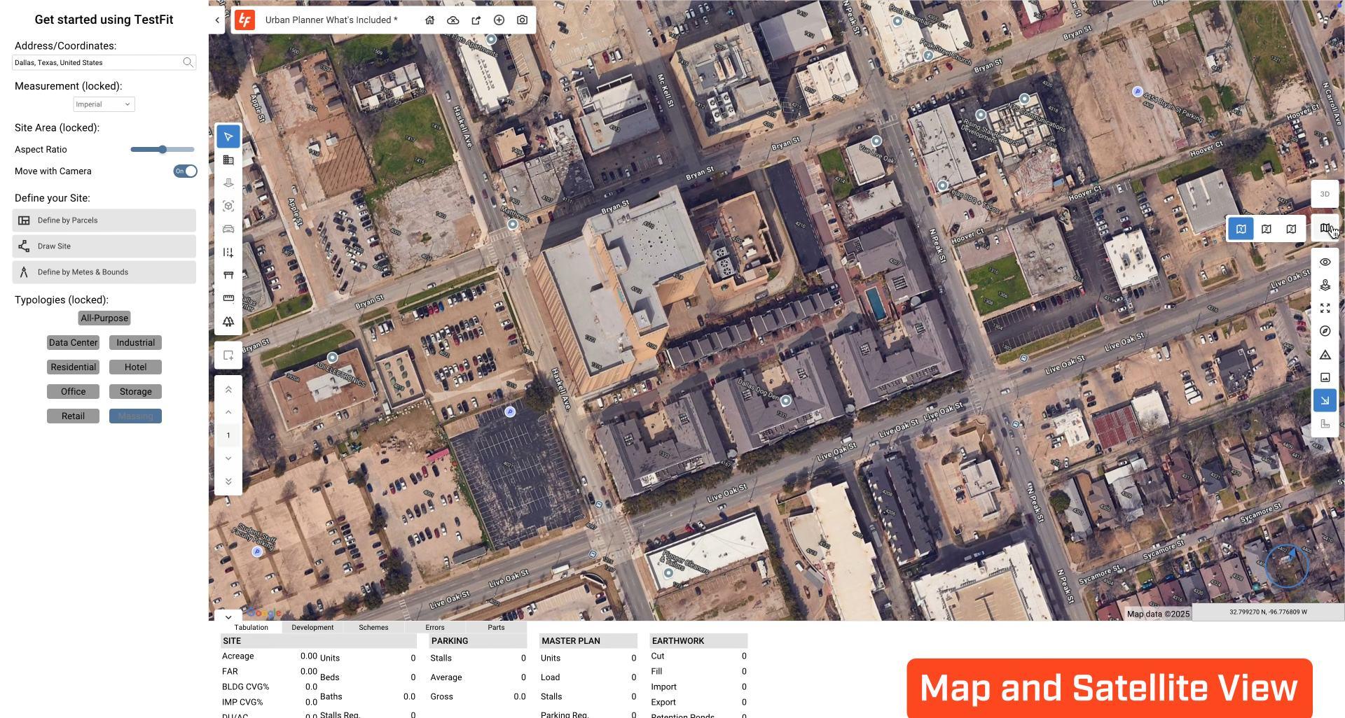
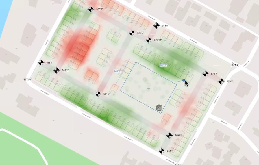
TestFit is a real-time site planning platform that enables architects, developers, and urban designers to rapidly test building feasibility on specific plots. It automates zoning compliance, massing studies, parking layouts, and unit mixes based on market, cost, and site data. With instant visual feedback and parametric controls, TestFit streamlines early-stage design, supports faster decision-making, and minimizes overdesign and material waste—aligning with circular and adaptive planning principles.
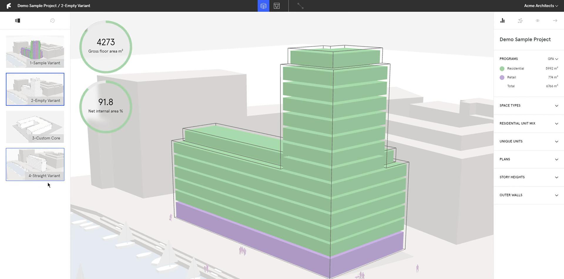
Finch 3D is a real-time generative design tool that helps architects quickly explore and iterate spatial layouts based on site constraints and program requirements. Originally developed for modular housing, Finch allows designers to adjust parameters such as plot size, density, height, and unit mix, with instant visual and data feedback. It enables efficient, adaptable design workflows in the early stages—bridging form, function, and performance to support sustainable, space-conscious planning.
GOALS
PROJECT
AGENDA DESIGN STATEMENT
HOLOLAB DESIGN GOALS
HoloLab reimagines architectural construction by transforming demolition waste into intelligent, customizable design systems.
Through an integrated digital workflow that combines material categorization, environmental analysis, parametric design, and machine learning,
creation of modular, scalable structures using recycled materials.
HoloLab enables the Custom 3D-printed joints and innovative assembly methods support construction across urban, residential, and public spaces.
With a strong focus on circularity, the platform empowers architects and designers to reduce waste, lower material costs, and build more sustainably to a more responsible and adaptive built environment.
. HoloLab turns construction debris into high-performance architecture, offering a forward-thinking approach
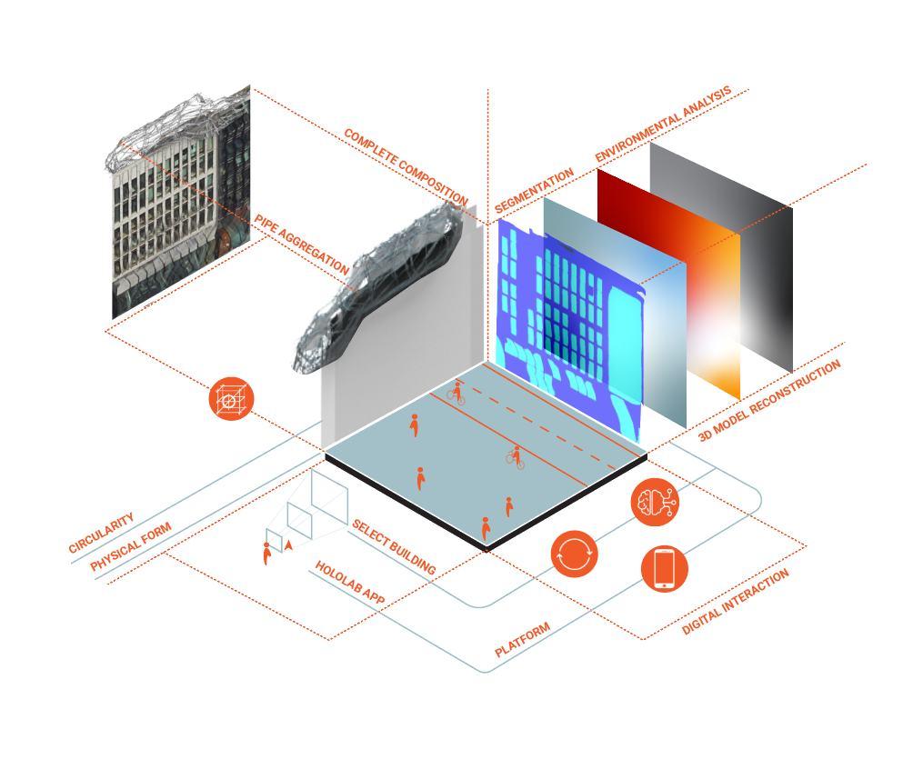
CREATING STRUCTURES
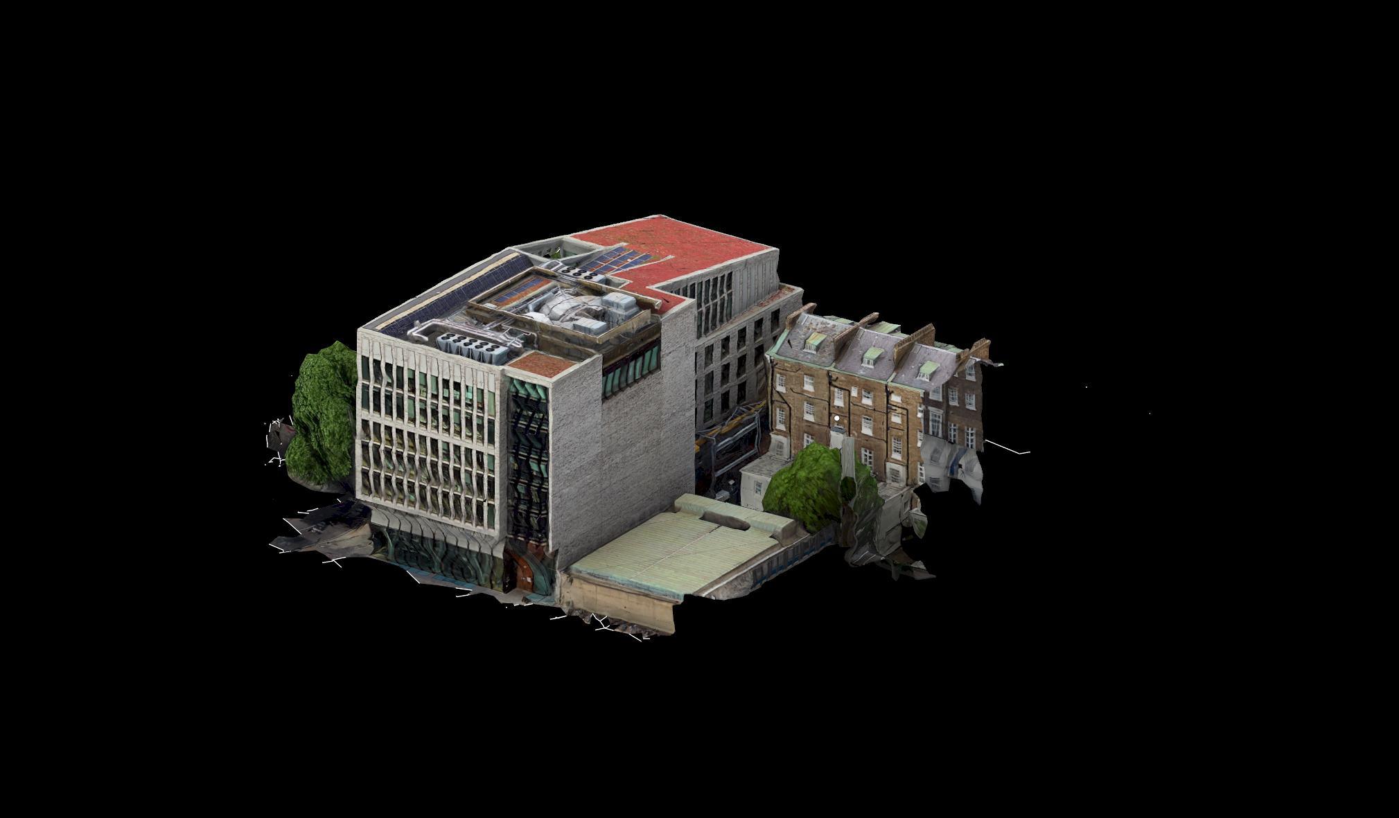
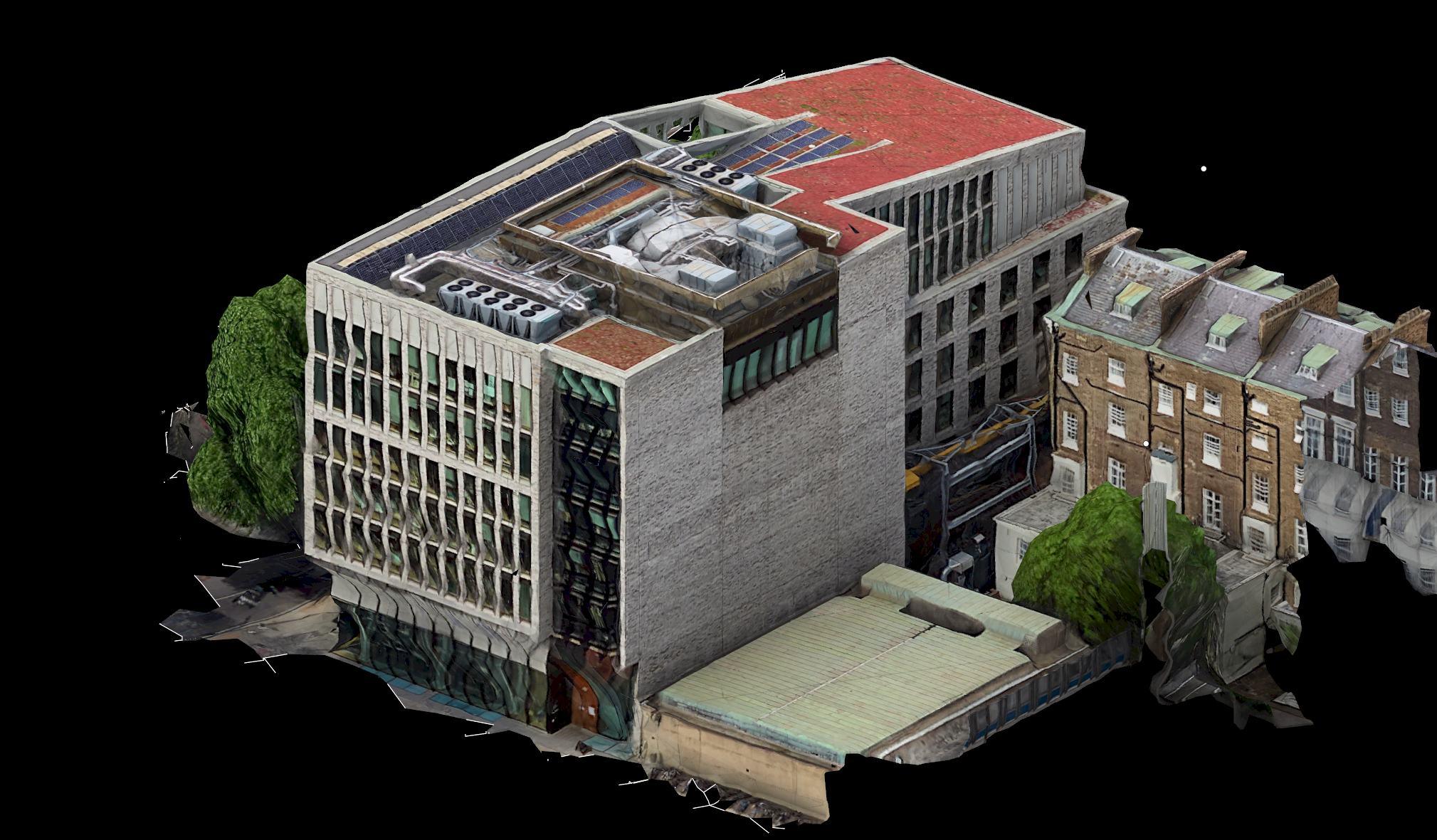
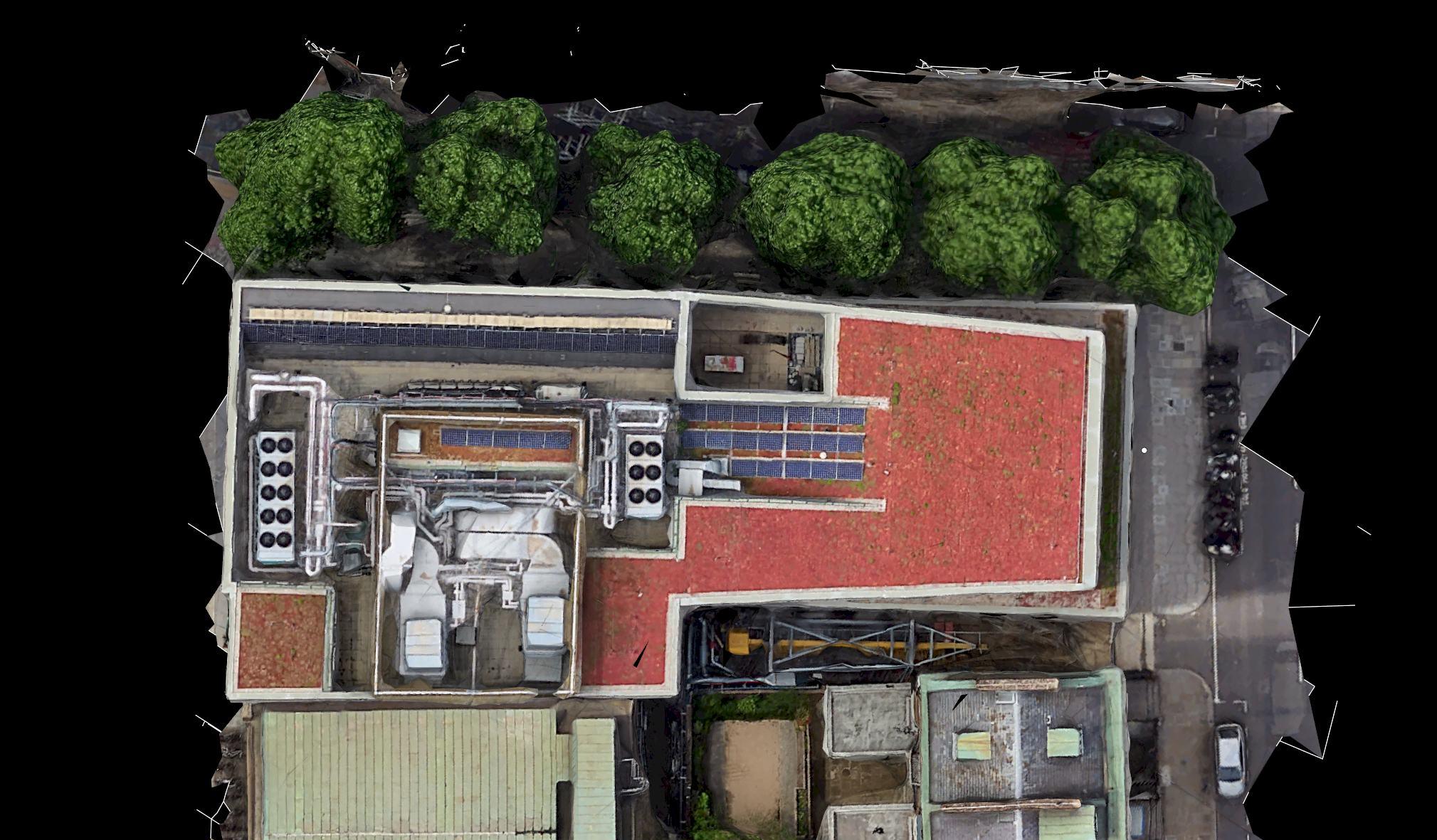
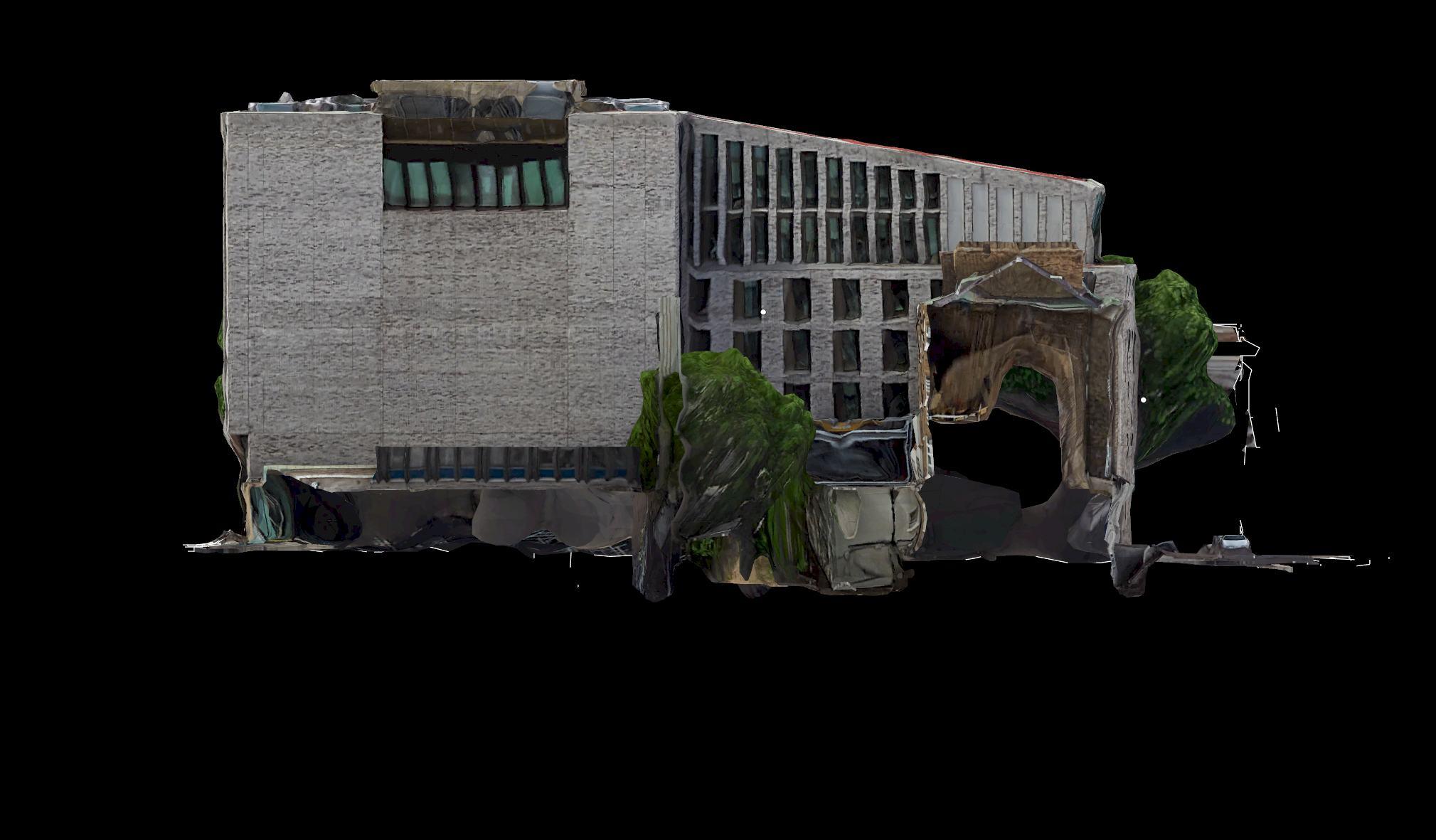
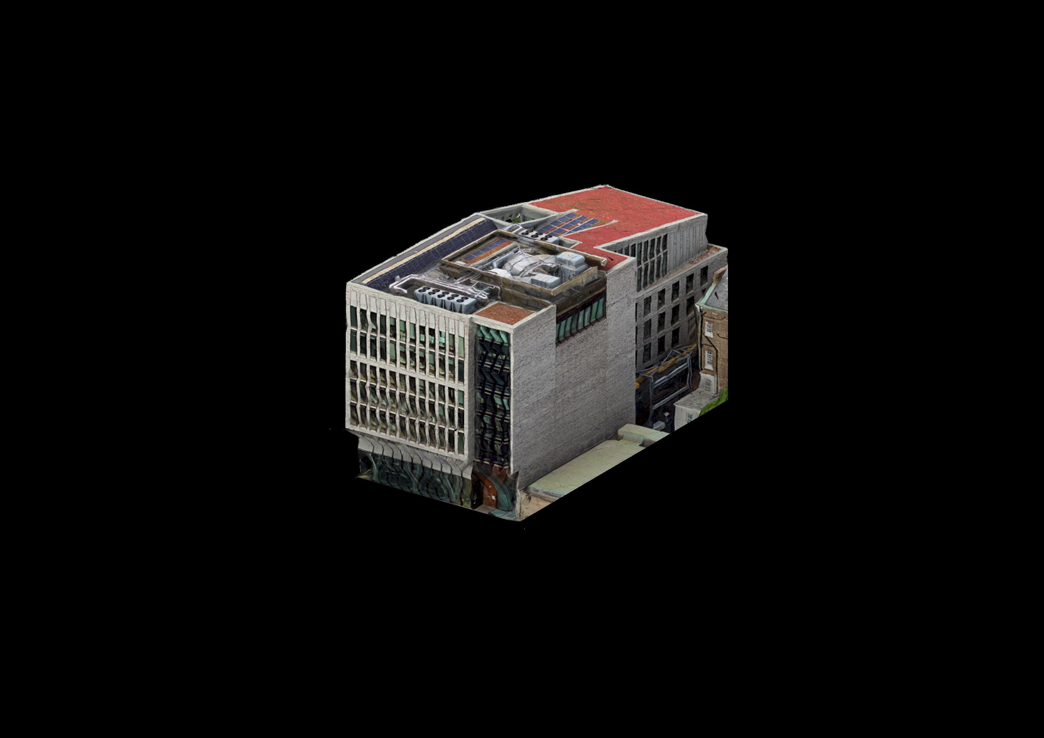
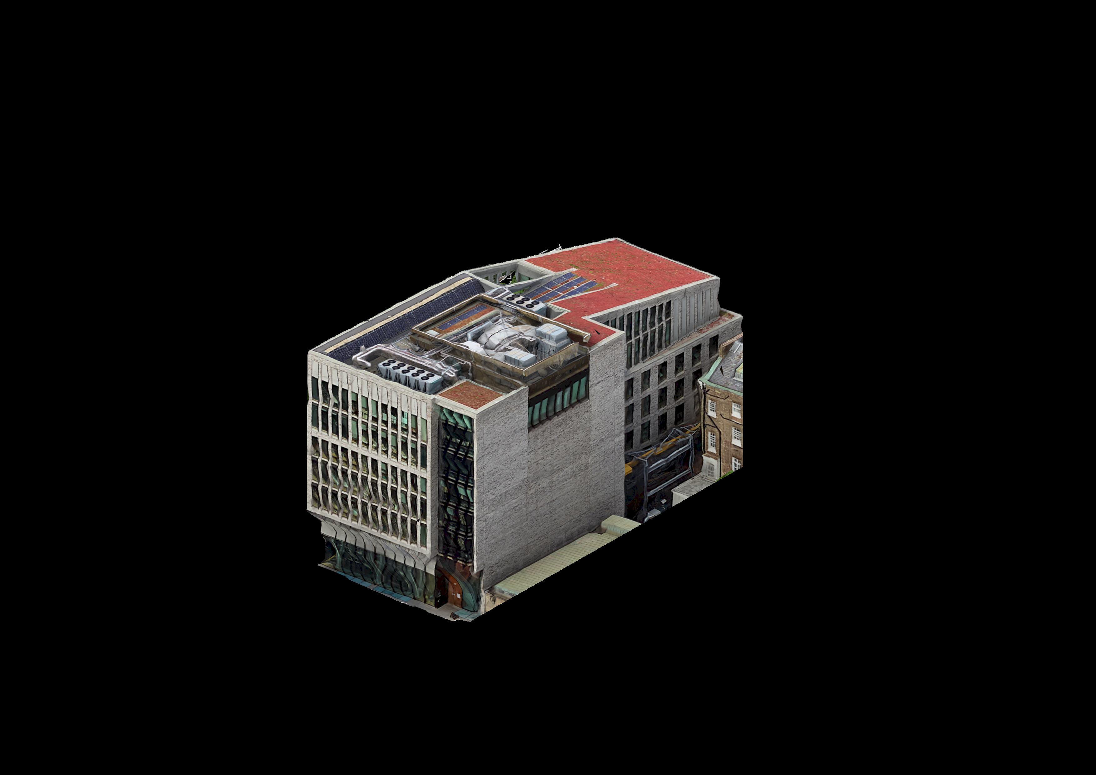
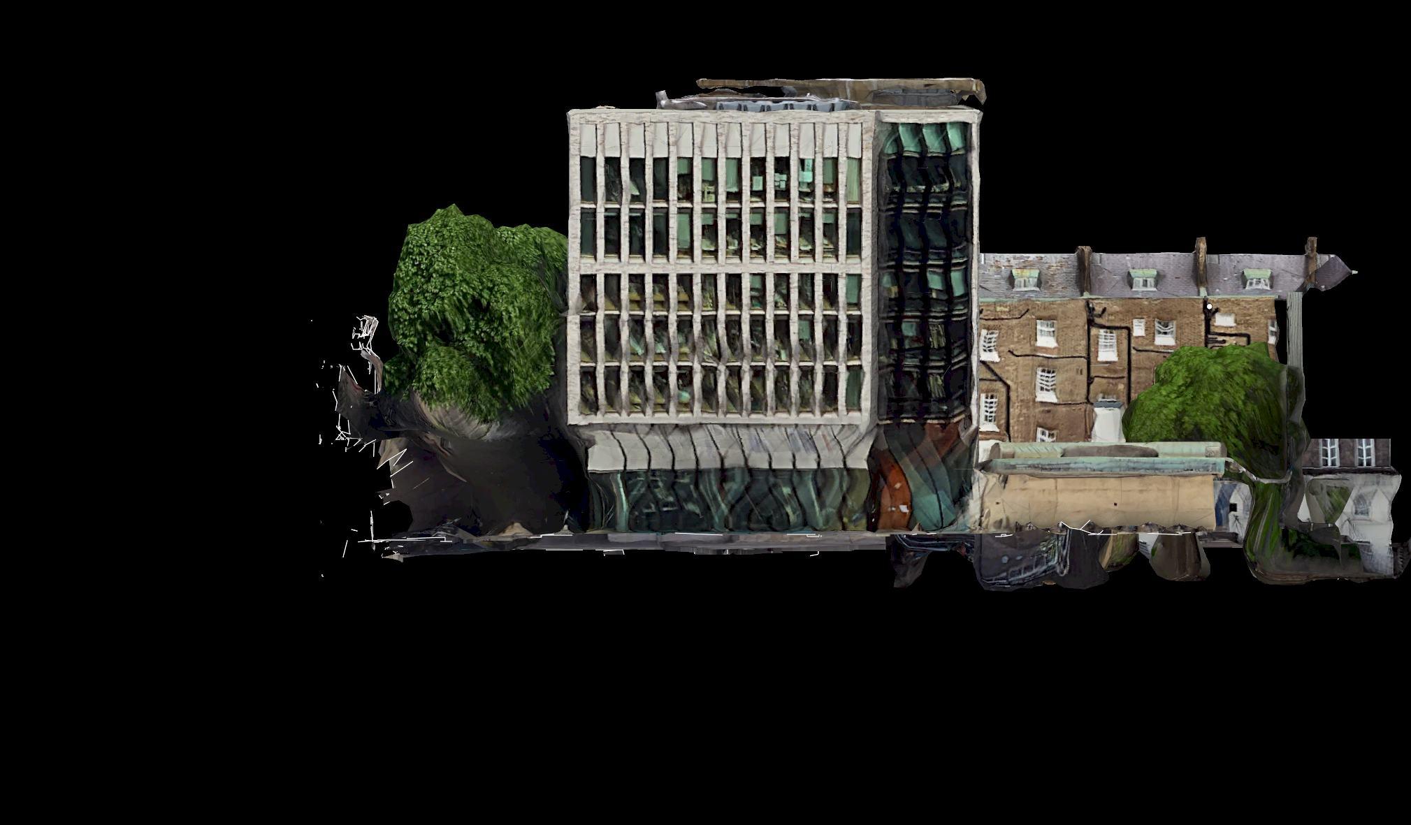
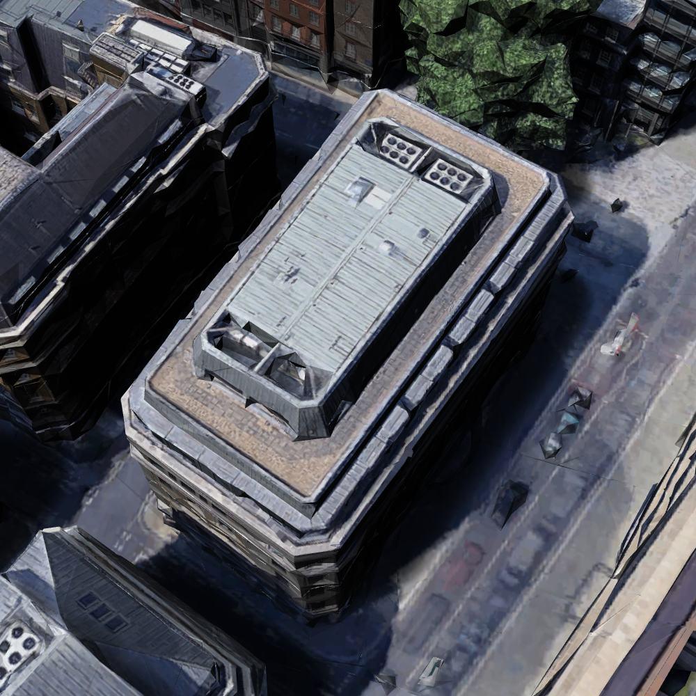
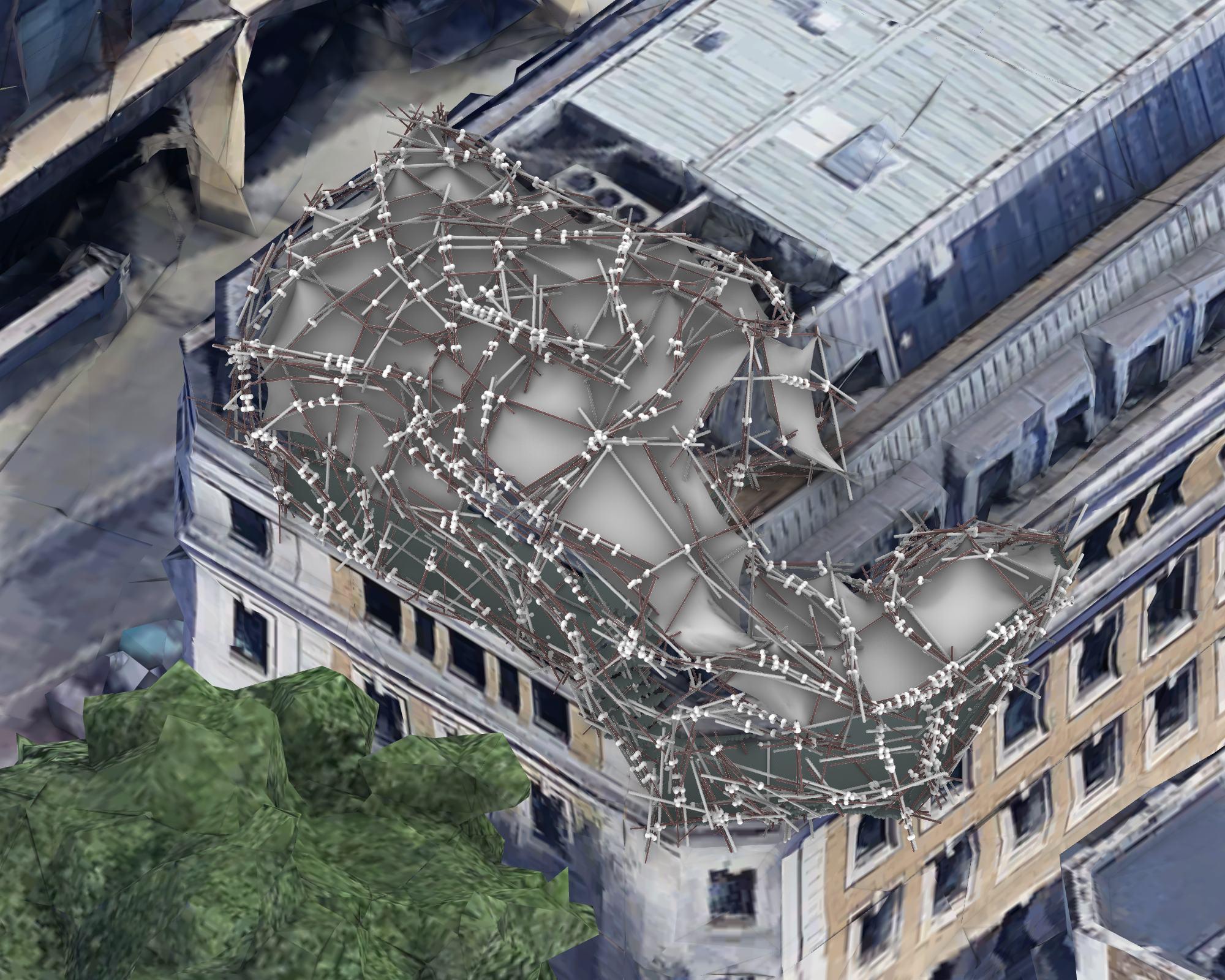
Hololab’s cyclical design process, integrating digital and physical workflows to create structures from reclaimed materials.
This diagram illustrates Beginning with building selection and environmental analysis, 3D scanning and segmentation inform precise digital reconstructions.
These models feed into the Hololab platform, where aggregation logic and circular design principles guide pipe-based compositions. The process bridges data-driven insights with adaptable physical forms, enabling sustainable, site-responsive structures.
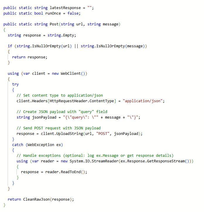
FRONT-END TO BACK-END
FRONT END USER FLOW
BACK-END PROCESSES
PROCESS OVERVIEW
Multi material
database Back end algorithmic processing INPUTS PROCESSING
BACK END - COMPUTATION
DATABASE
AI IMPLEMENTATION
ENVIRONMENTAL ANALYSIS
USER PREFERENCES
PIPE GENERATION
DATABASE
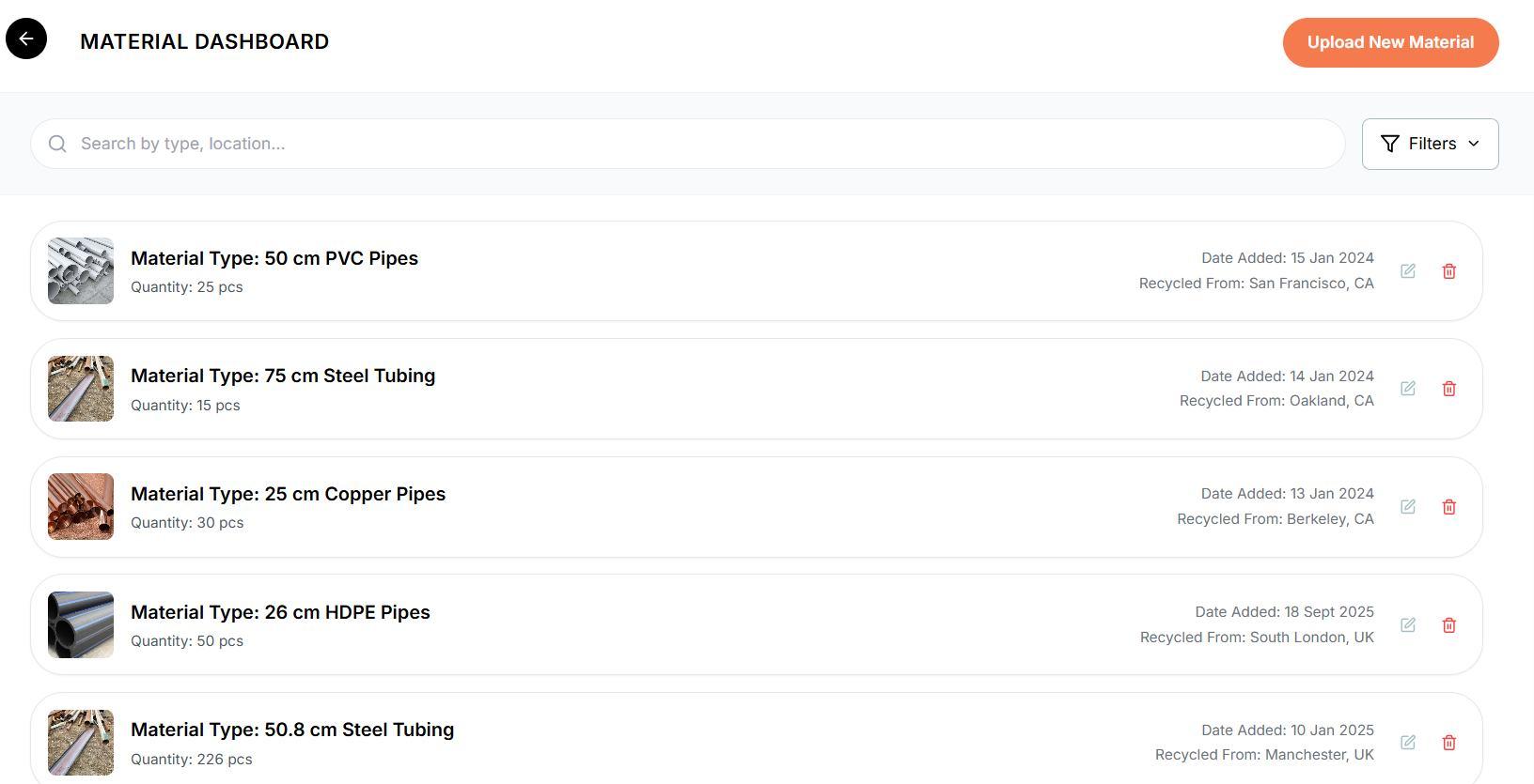
Creating a database is necessary for our design method because it It allows structures to evolve organically without compromising design.
Without a . It allows the platform to perform environmental and structural analysis based on real-world inputs, ensuring each design is both contextually optimized and materially feasible.
The database becomes the foundation for recommendations, and informed decision-making throughout the design process. kickstarts the entire circular design workflow by organizing and categorizing available reclaimed materials reliable database, intelligent matching between design intent and material availability would not be possible . enabling scalable reuse
Refer to appendix pg. 126 for more content.
Multi material
database INPUTS
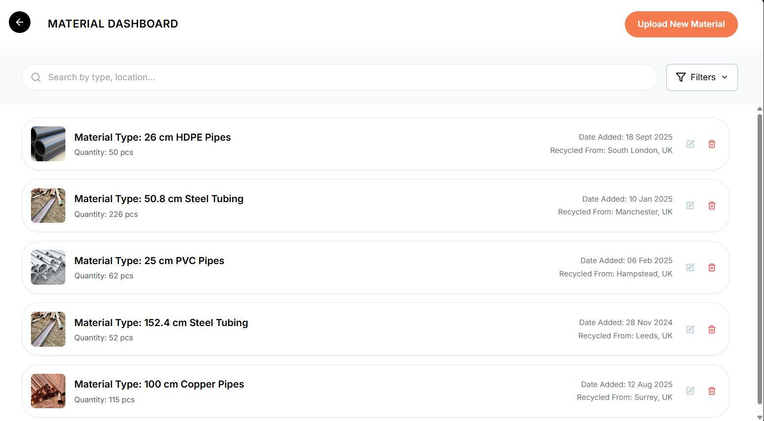
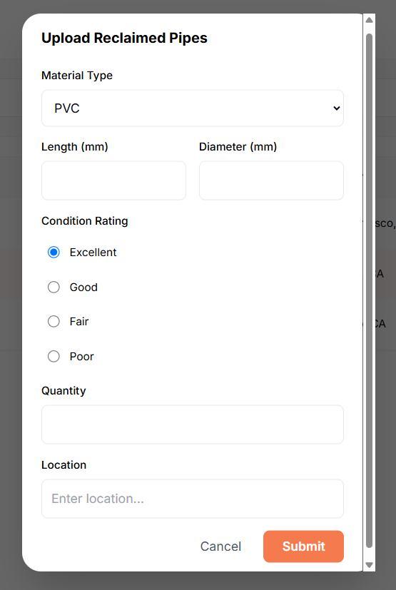
DATABASE CREATION - MANUAL
Manually . It allows for detailed metadata (e.g. condition, dimensions) to be recorded and standardized for reliable use across multiple projects. inputting materials into the database ensures accuracy and traceability
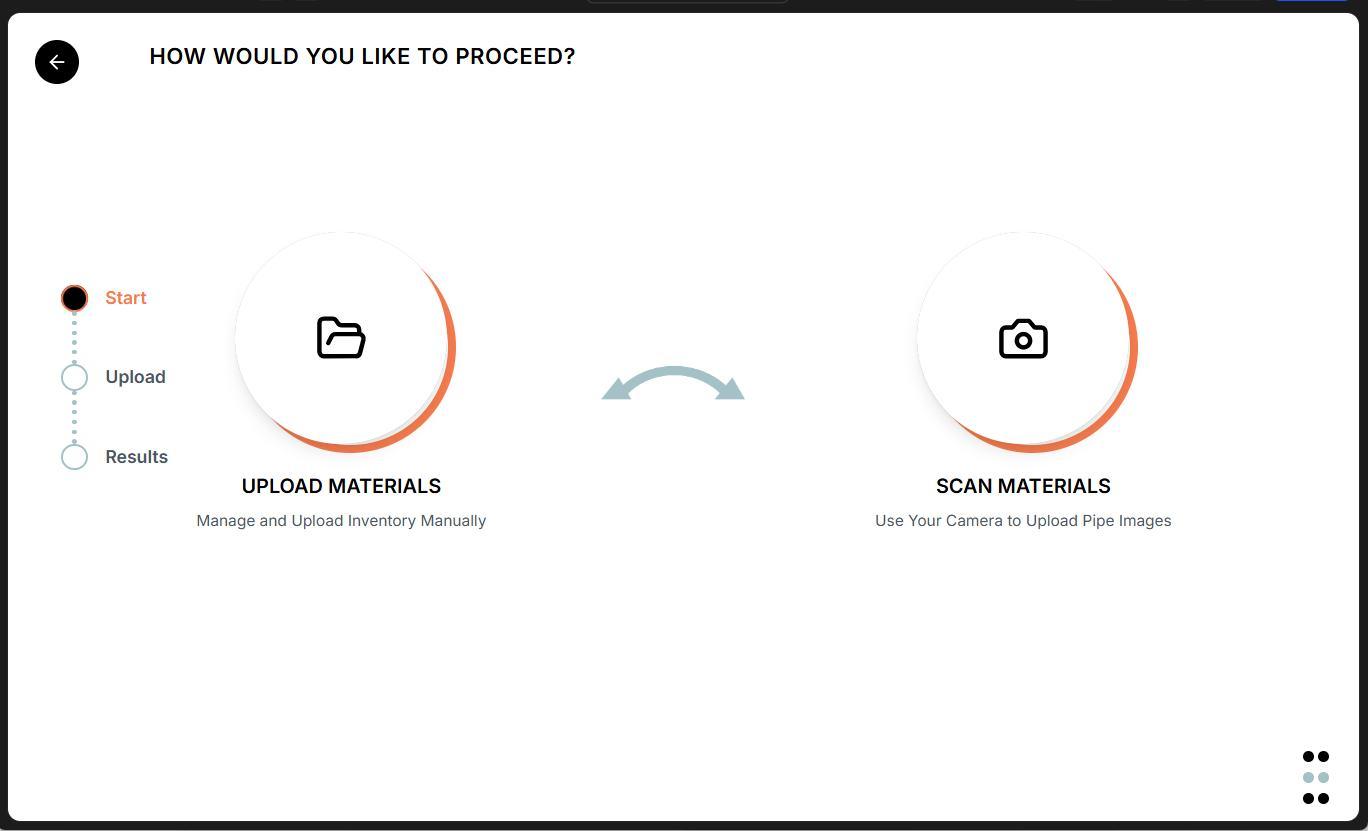
Option to manually enter material data...
DATABASE CREATION - SCAN TO UPLOAD
The scanning feature empowers everyday users to contribute directly by . This accelerates the reuse process, and supports real-time updates to the database based on what’s actually available in the field. capturing data on-site using just a device
MACHINE LEARNING OVERVIEW & PROCESS
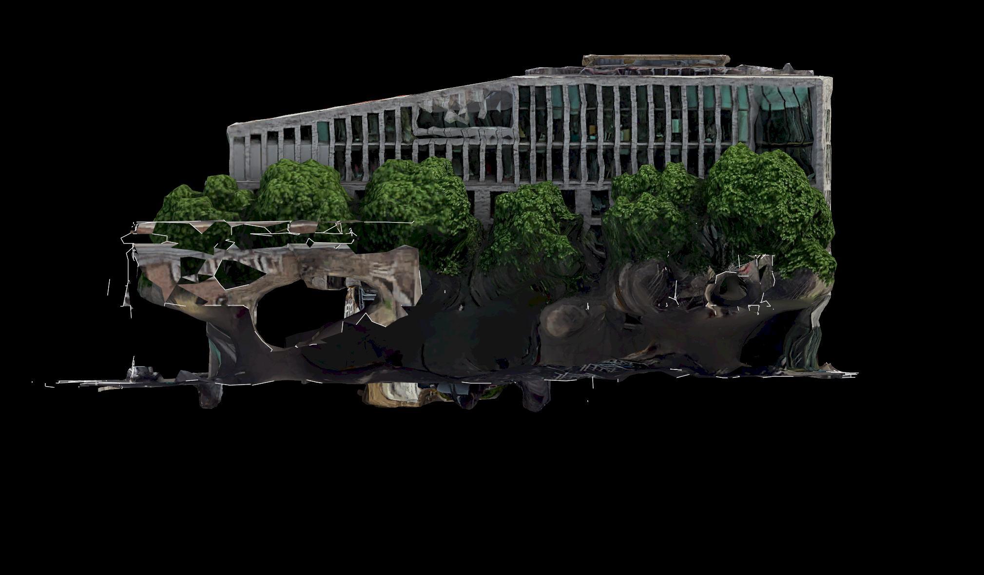
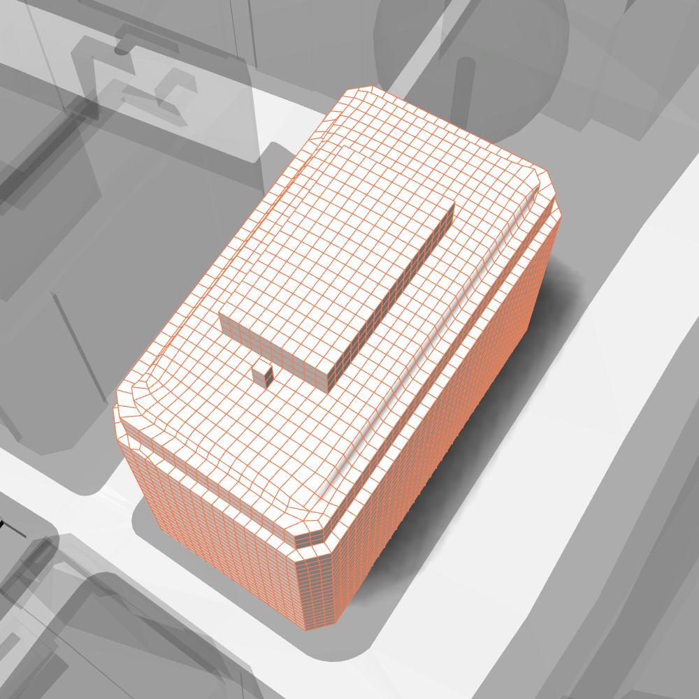
Machine learning algorithms segment the building into discrete areas , automatically detecting key zones of interest. Finally, users can fine-tune these results, producing an accurate, customizable model ready for integration into retrofit planning, material mapping, or other analytical workflows.
Refer to appendix pg. 143-150 for more content.
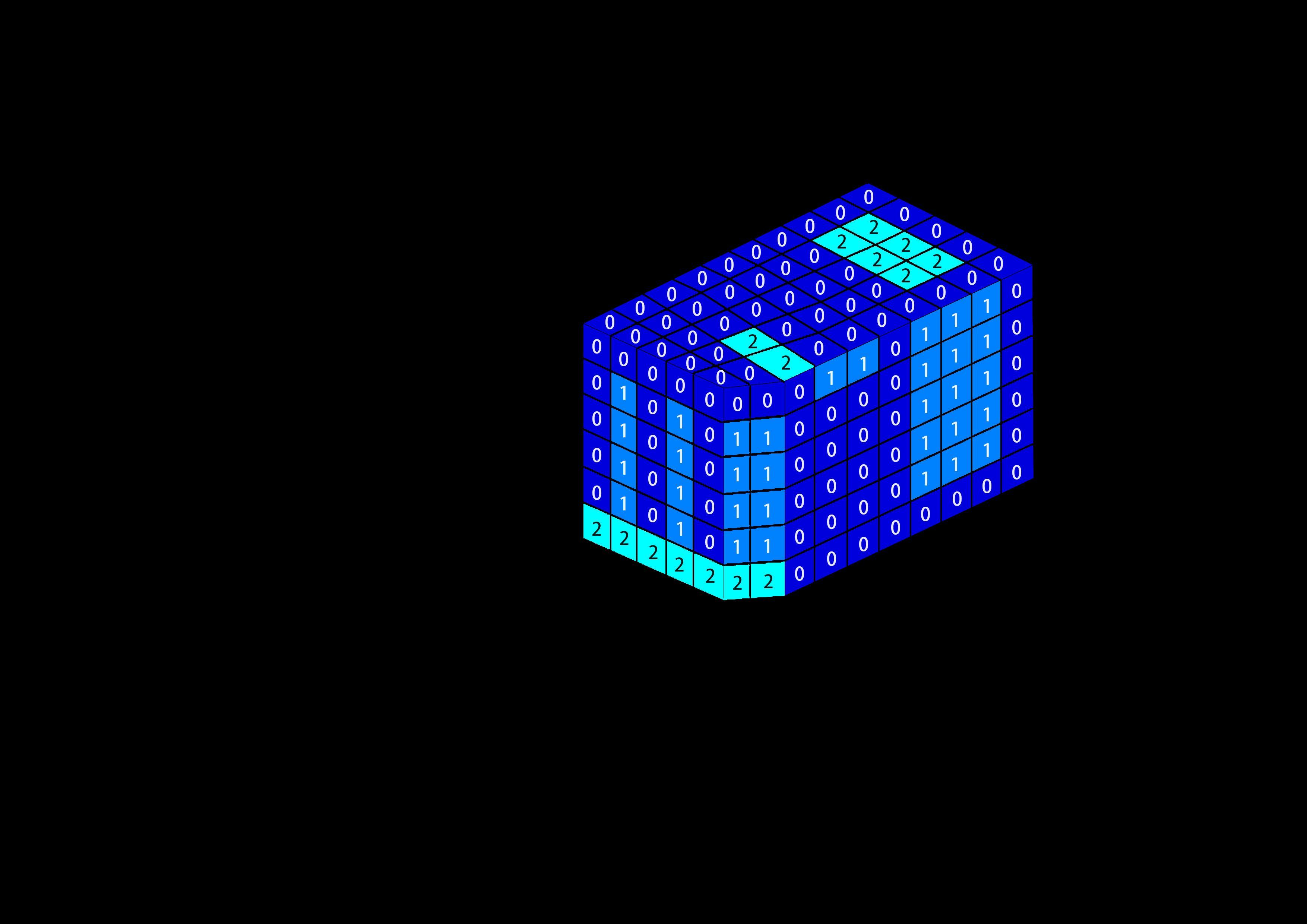
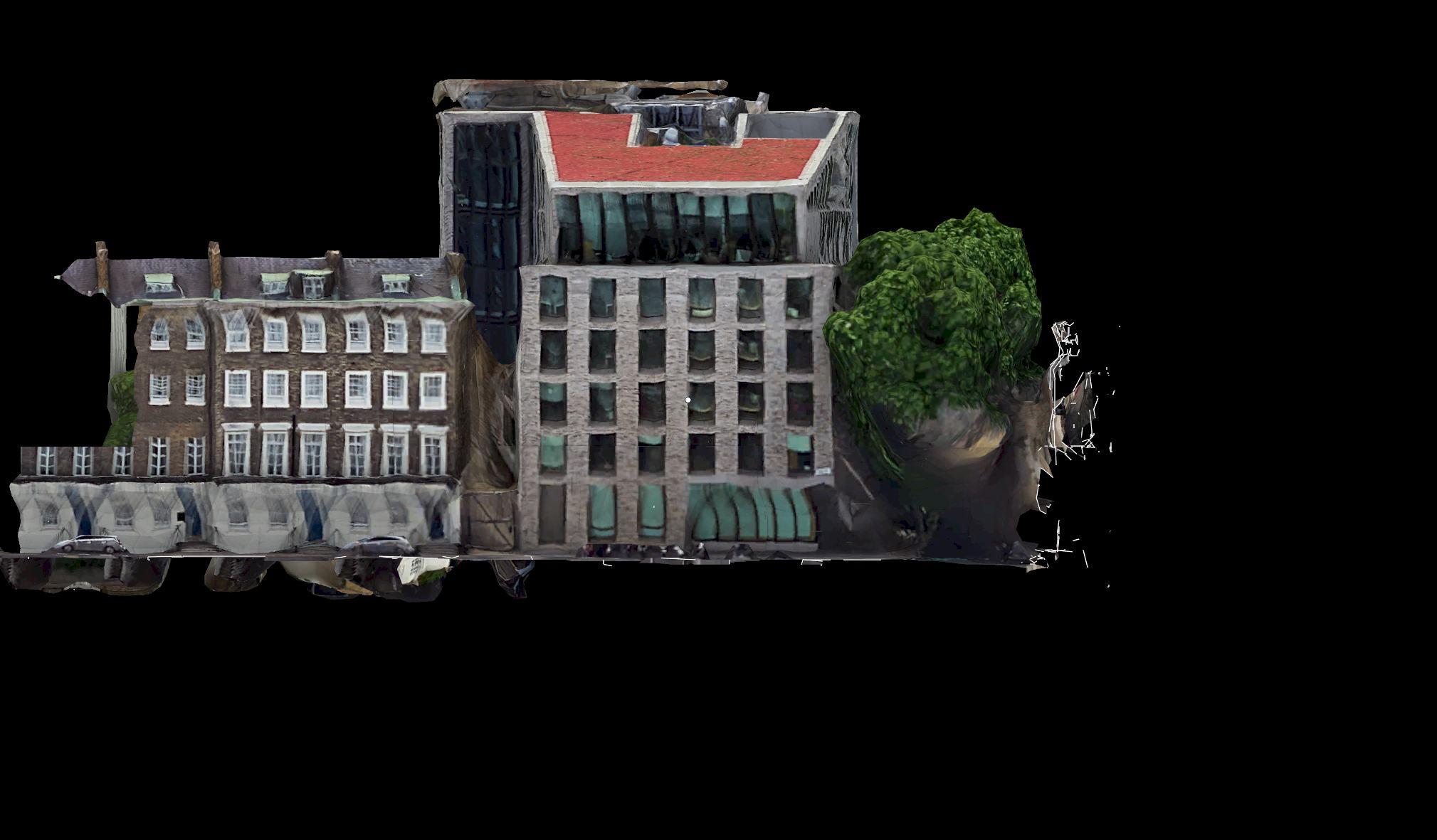
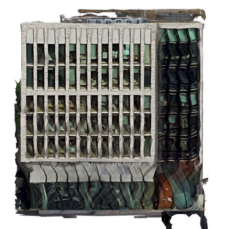
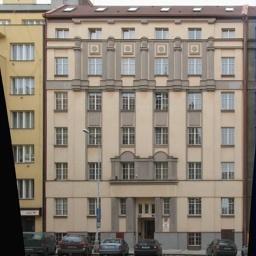
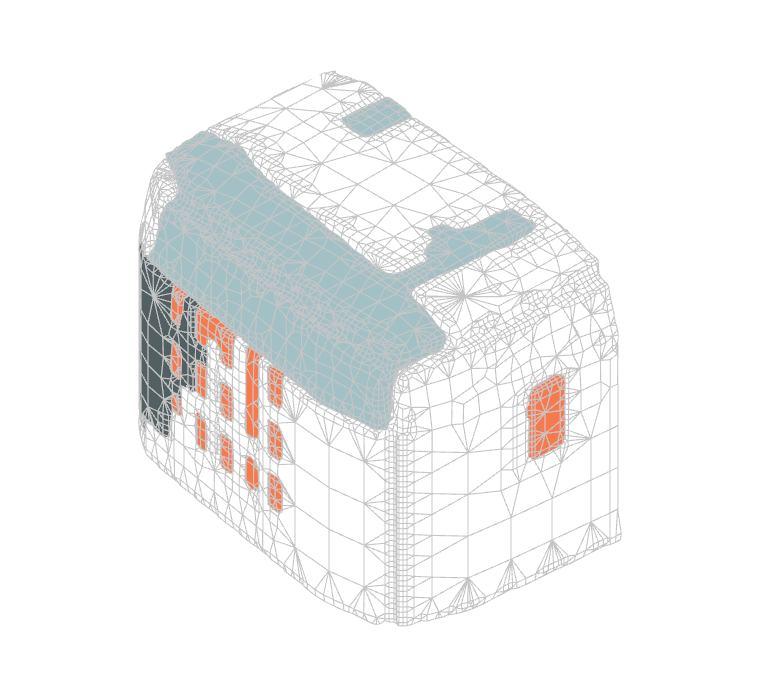
BUILDING SEGMENTATION
MACHINE LEARNING - SEGMENTATION
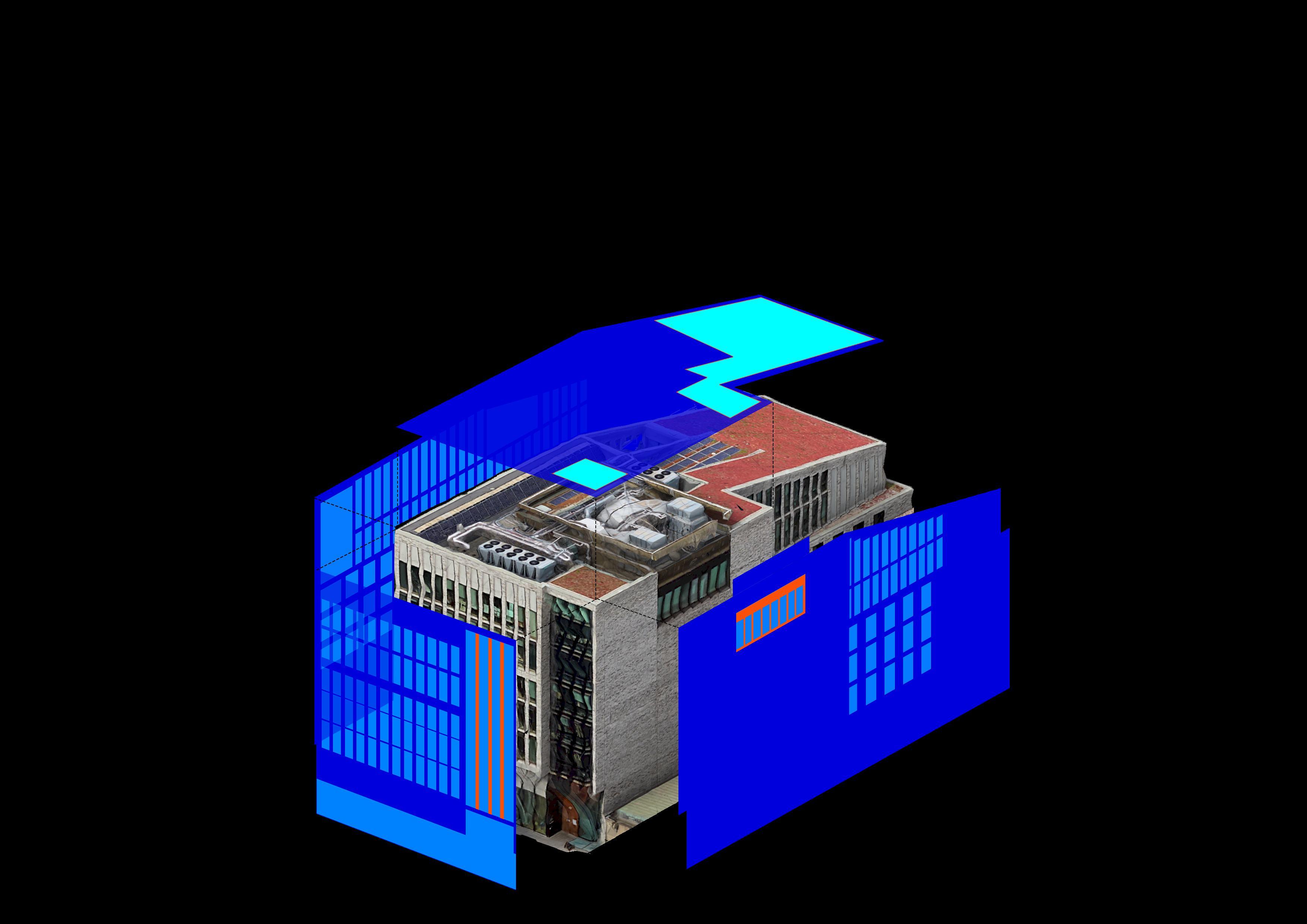
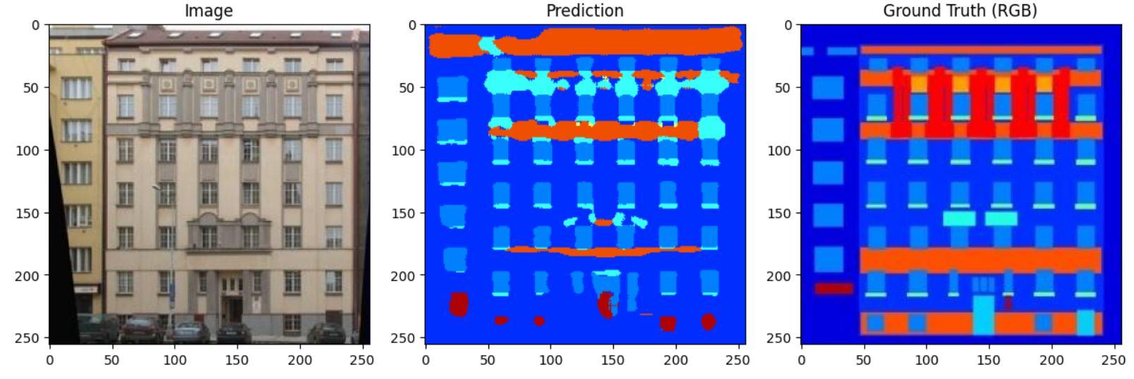
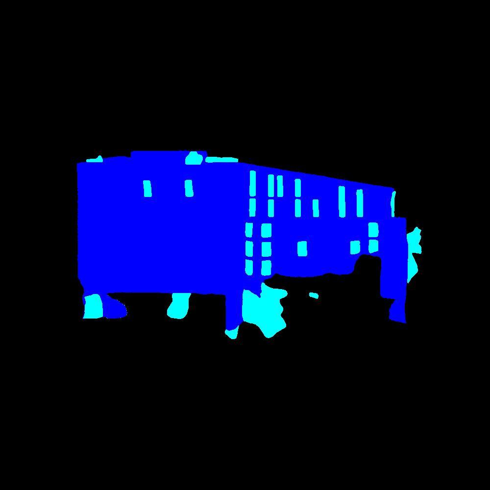
On the back end, the system decomposes the model’s façade into high-resolution imagery, which is
. These classifications are projected back onto the 3D geometry, producing a precisely labeled model. processed by a semantic segmentation model to classify elements such as walls, windows, pillars, and doors
SEGMENTATION
FRONT END BACK END - DECOMPOSITION + GENERATION
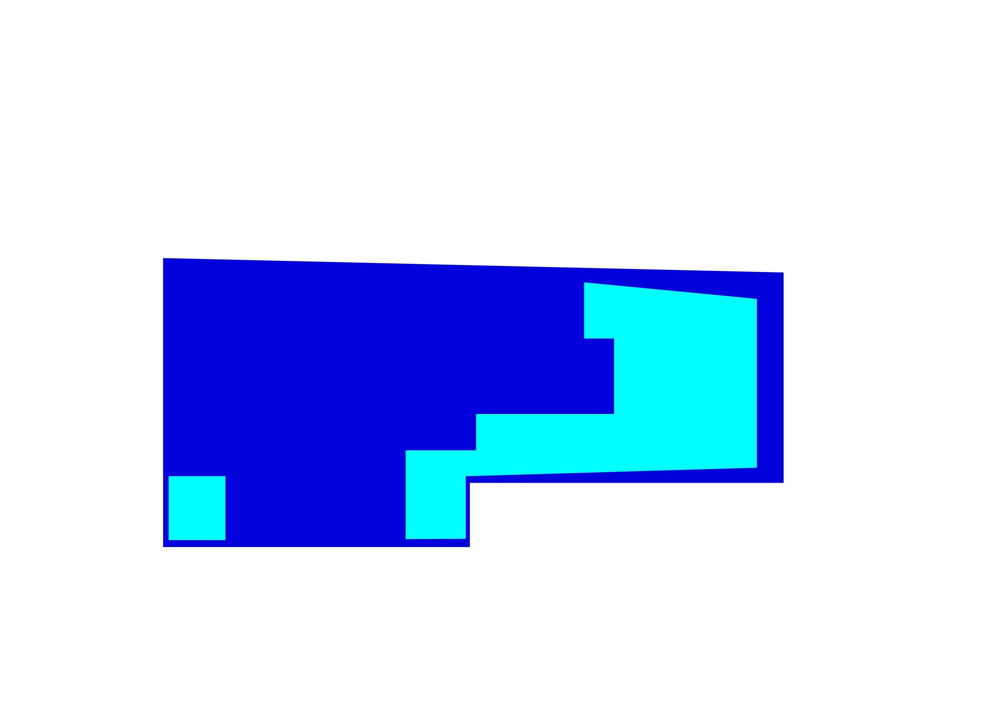
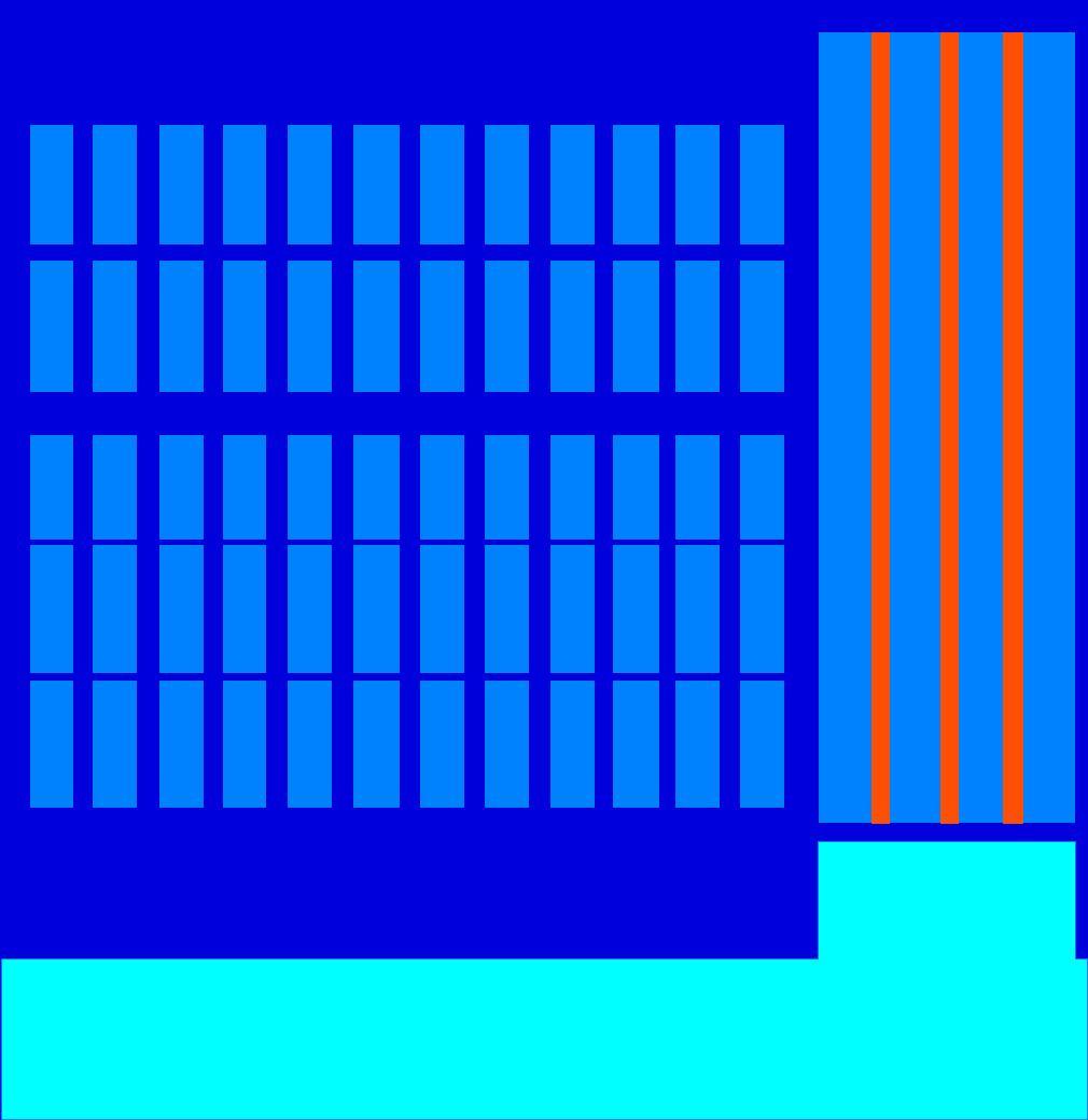
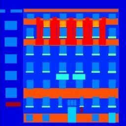
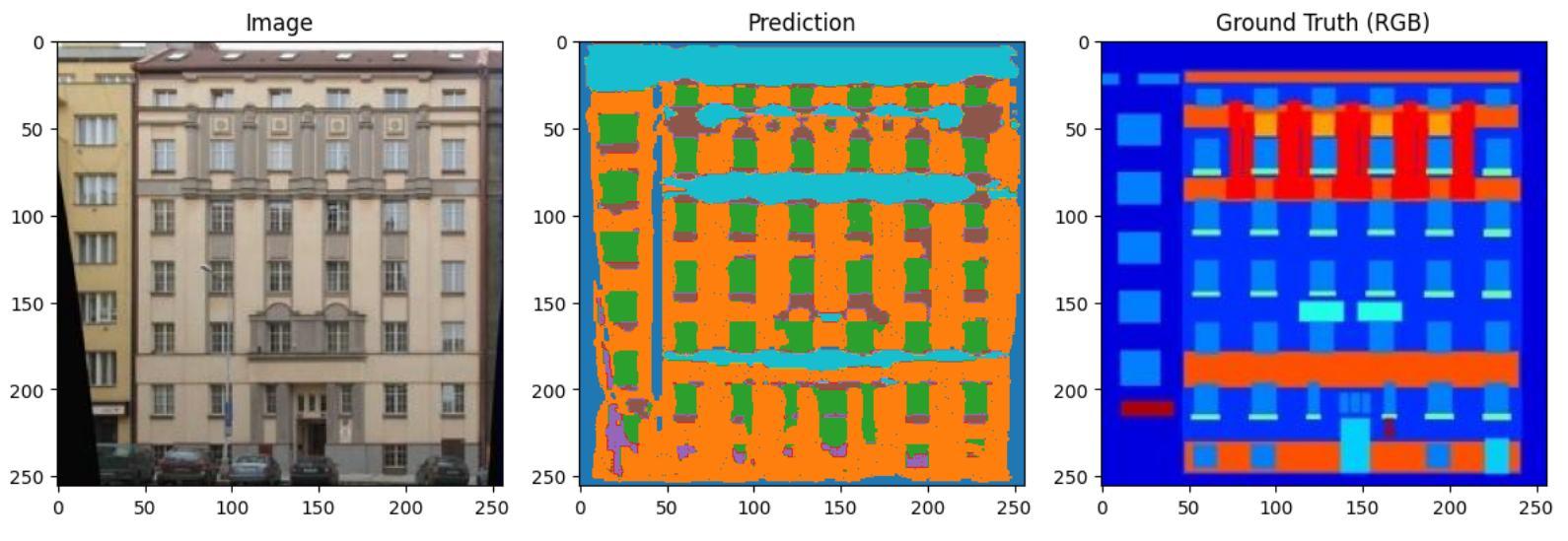
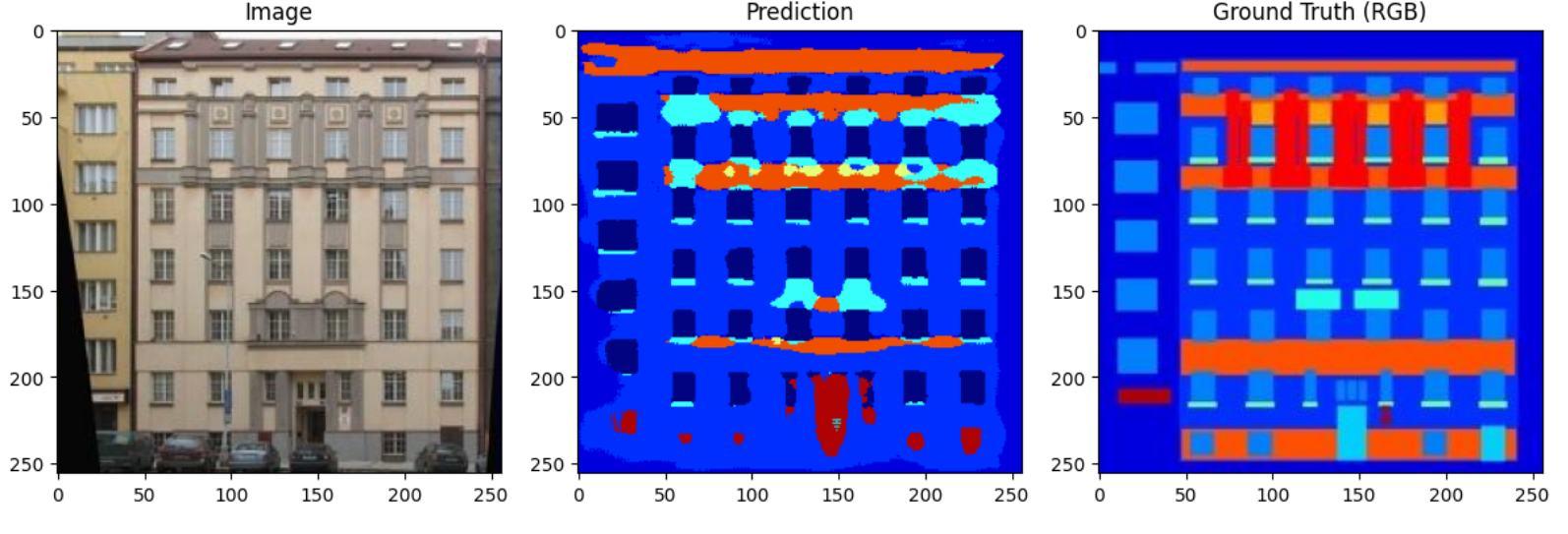
SEGMENTATION RESULTS
Refinements in color mapping improved prediction accuracy.
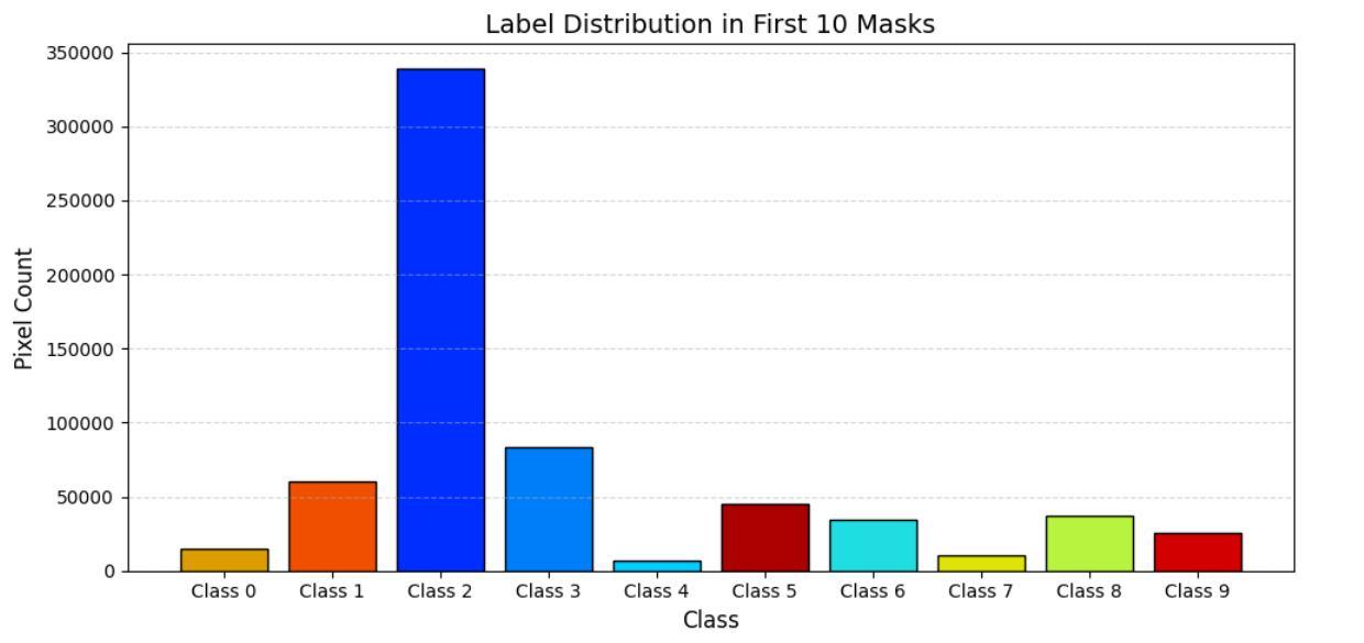
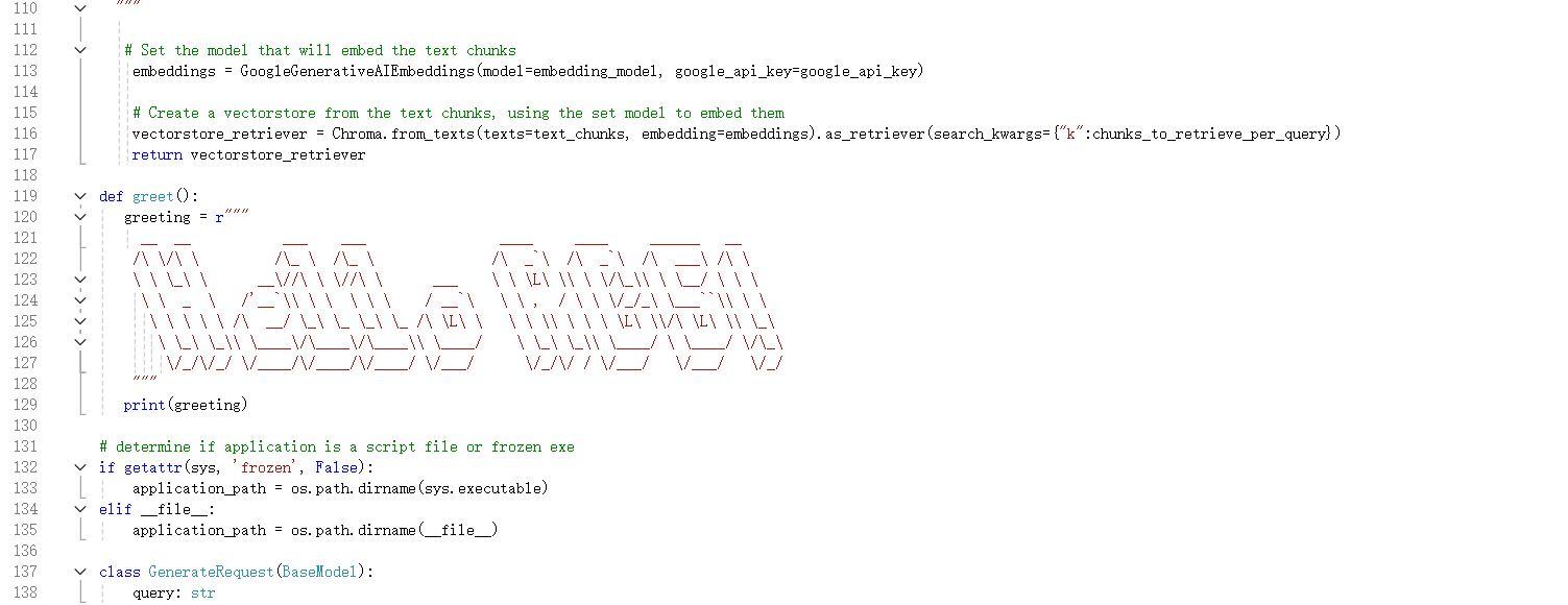
A revised color mapping system, shown in the embedded Python code, ensures clearer visual differentiation between classes, reducing misclassification errors. The training process begins with façade imagery, which is processed into segmentation masks that label architectural features.
TRAINING PROCESS
Sets a more accurate color mapping:
Results:
Counting the different labels and calculating the usable area:
Bartlett facade prediction results:
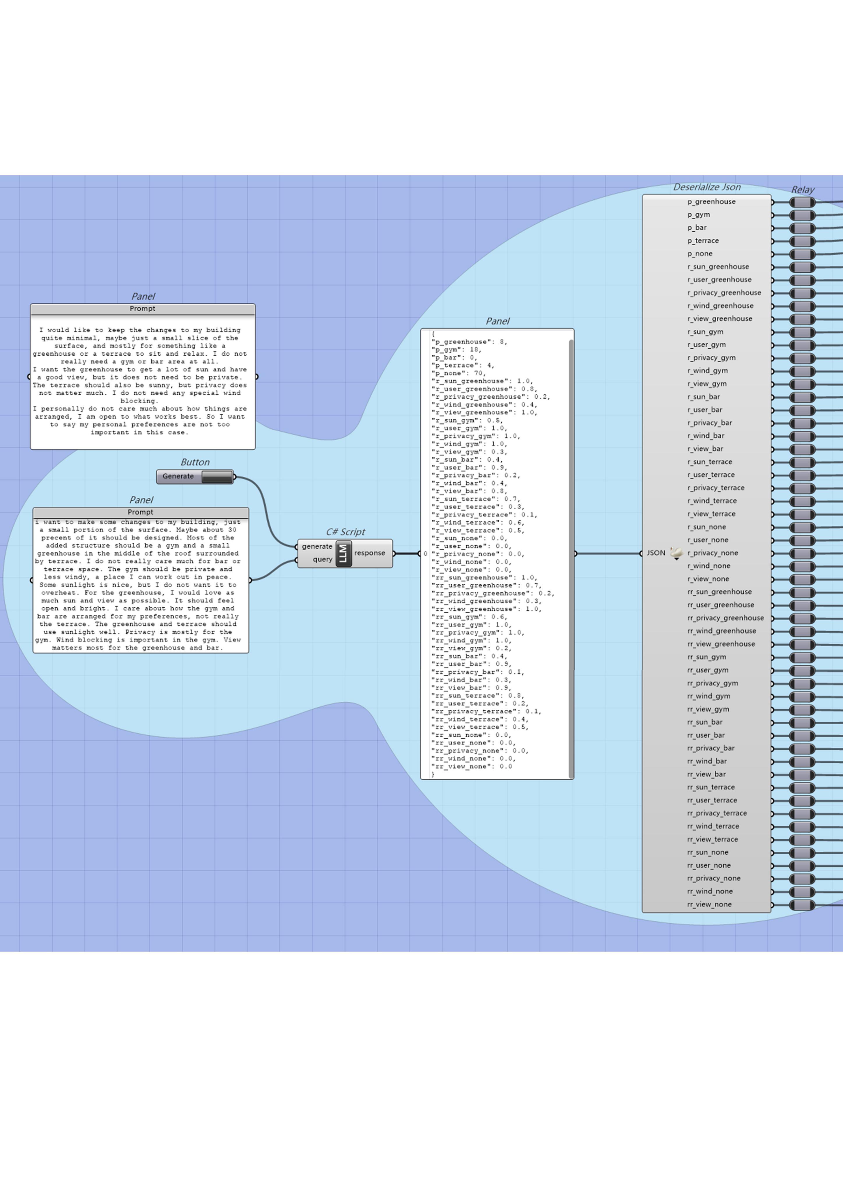
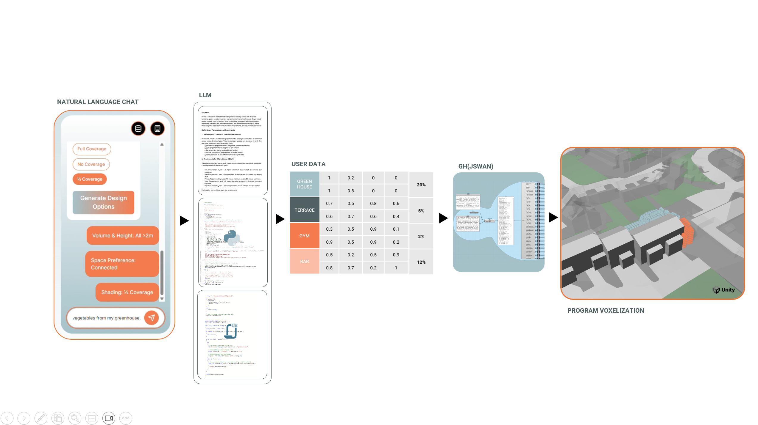
MACHINE LEARNING - SEMANTIC-GEOMETRY GENERATION
This system to convert the semantic requirements input by users into parameter definitions and geometric generation processes.
combines LLM and ML Model generation is driven by scripts and graphical algorithms, and visualised in real time.
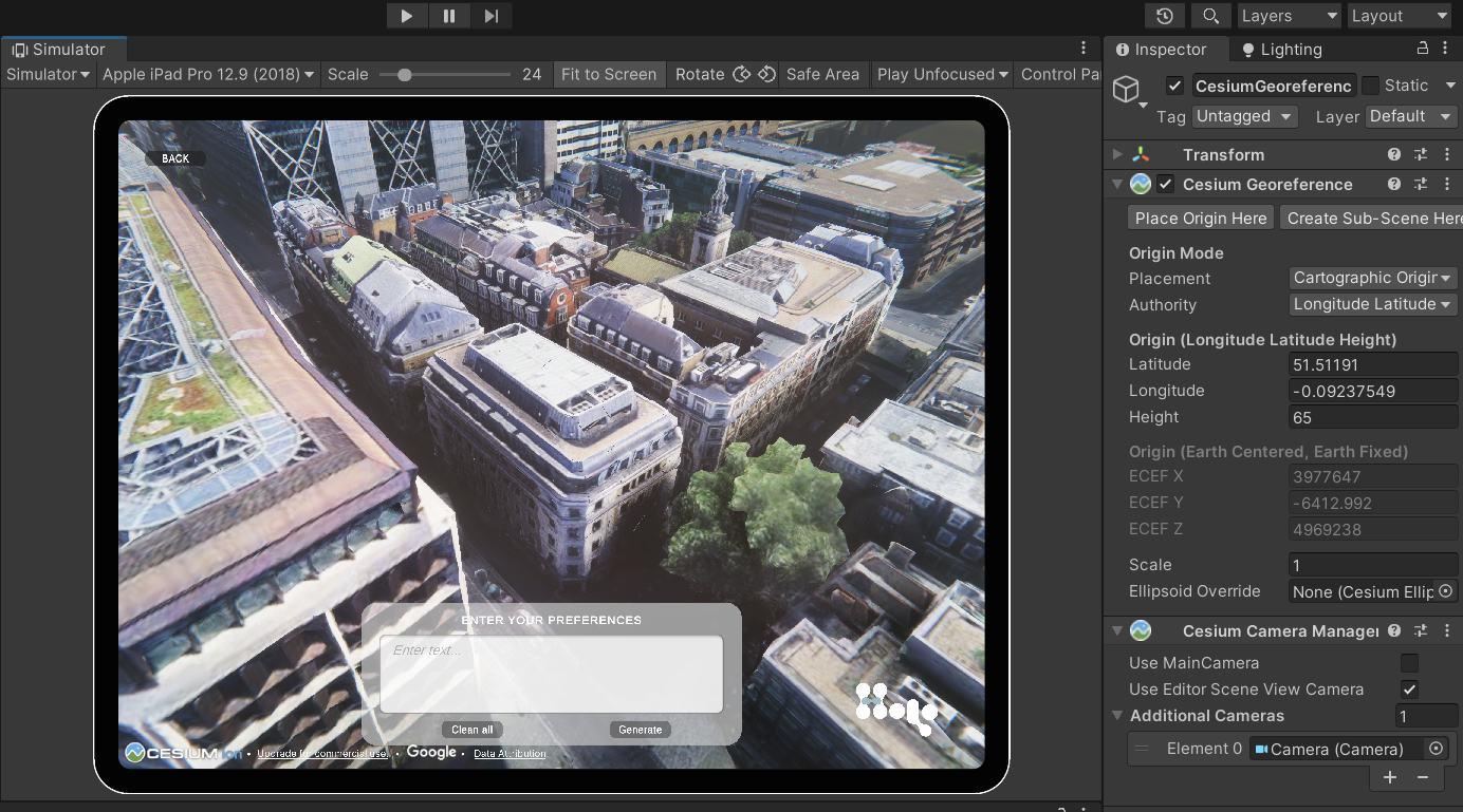
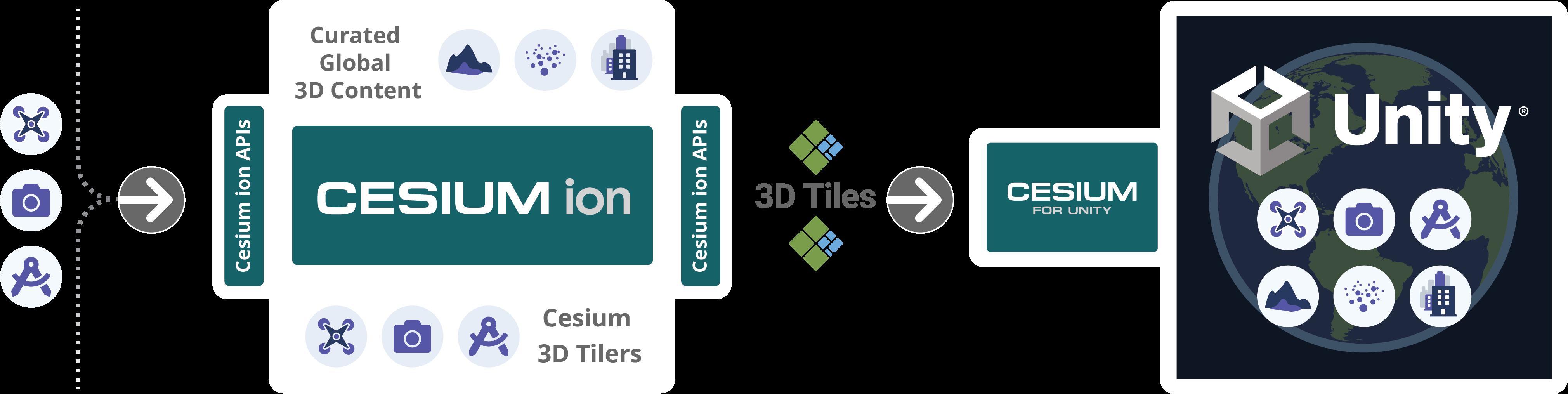
BACK END SITE FINDING
This system is based on, using Cesium and Unity to real coordinate data achieve rapid site selection and positioning of building models within the
ENVIRONMENTAL ANALYSIS - DATA COLLECTION
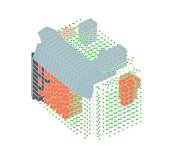
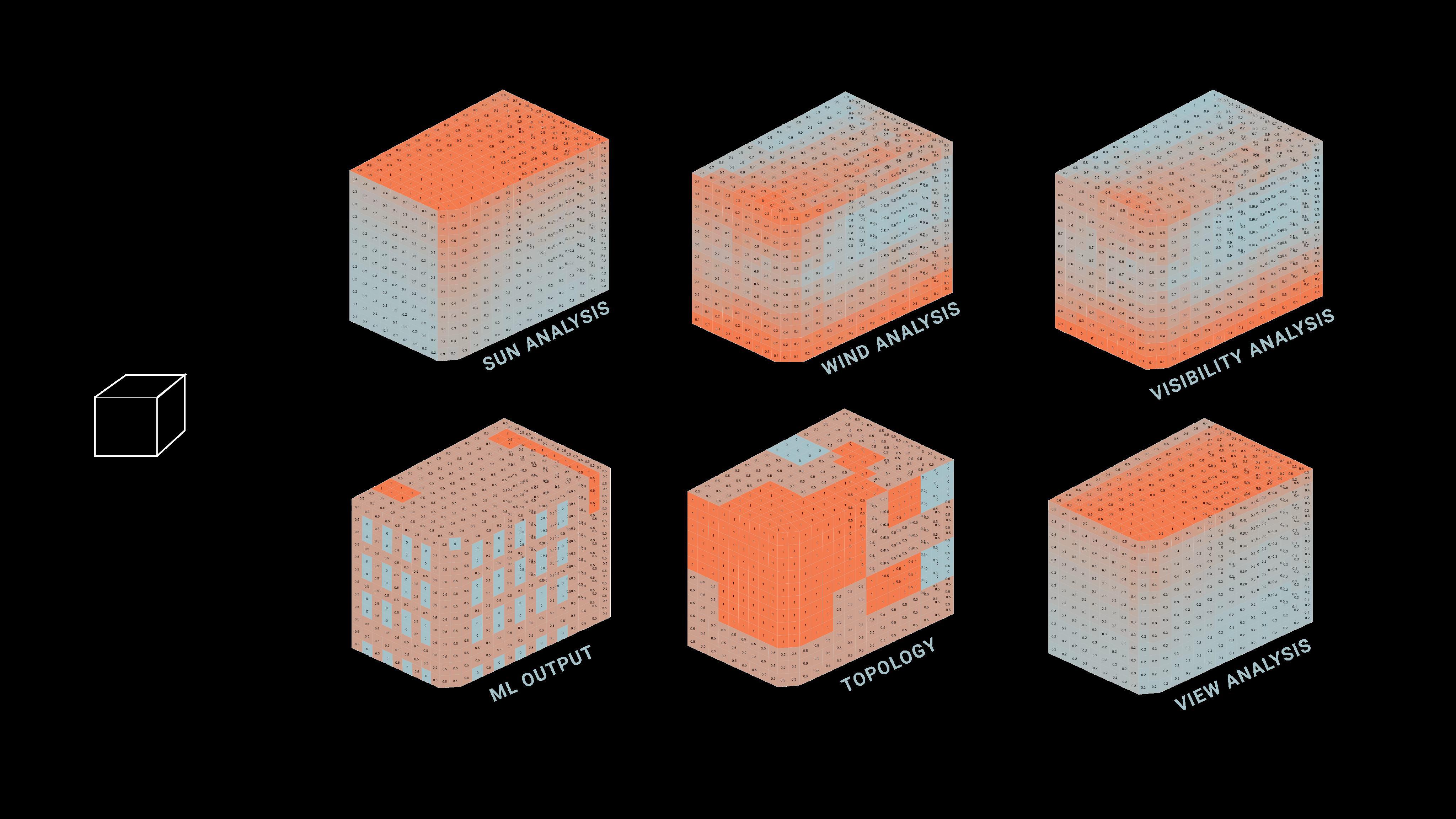
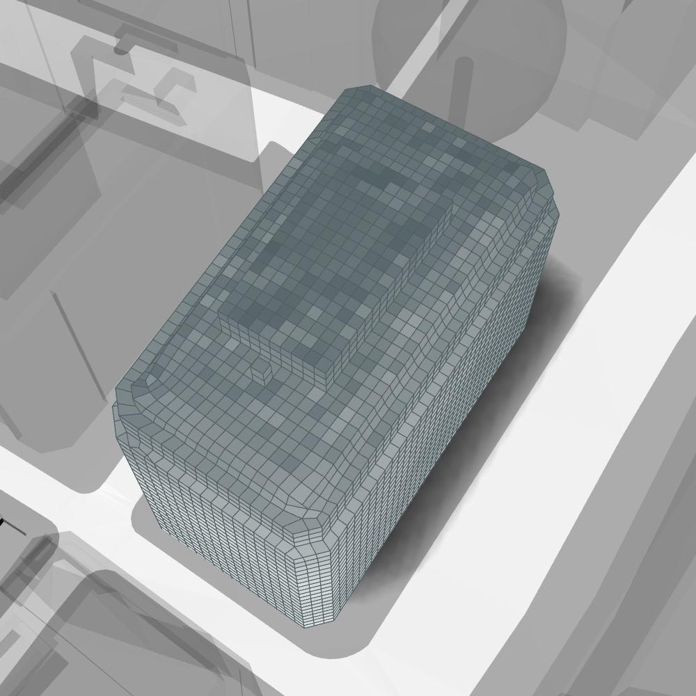
Environmental analysis is run on the geometry, considering the context as well as the geographical location of the building.
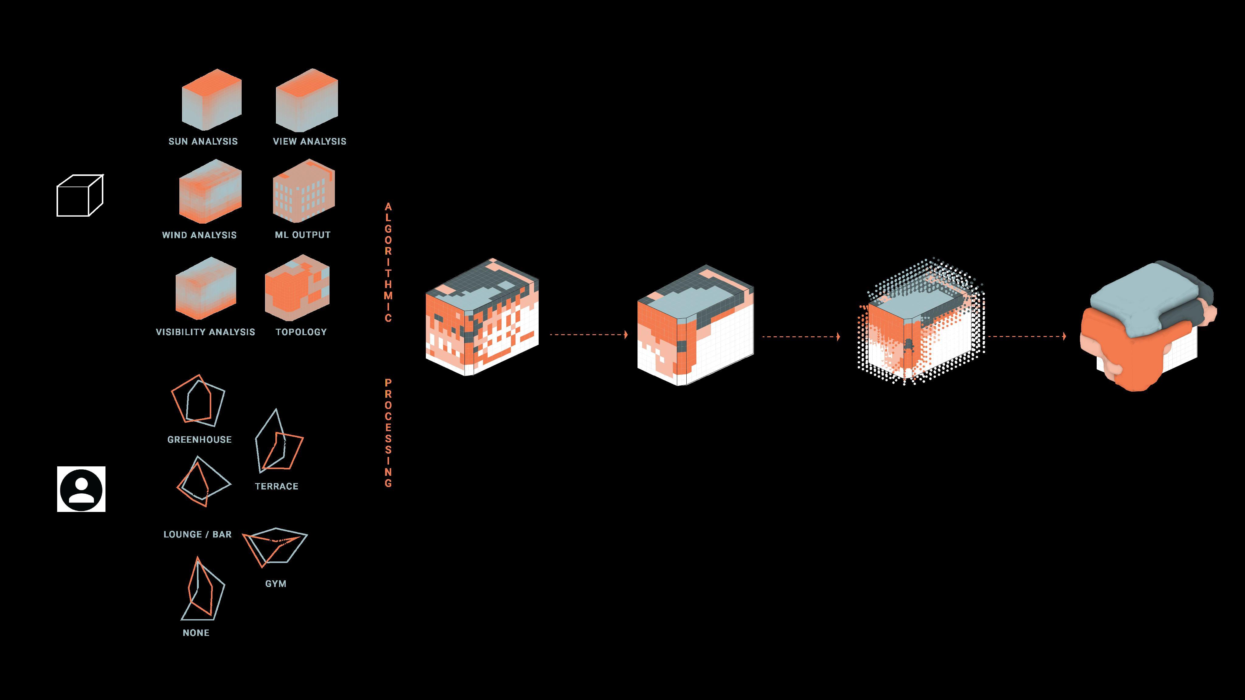
environmental analyses are sun daylight, wind exposure, visibility (view and privacy).
The They are run with the help of LadyBug Grasshopper. All these analysis inform the mesh of the building giving scores to each face.
Refer to appendix pg. 130-132 for more content.
INPUT COLLECTION
Refer to appendix pg. 133 for more content.
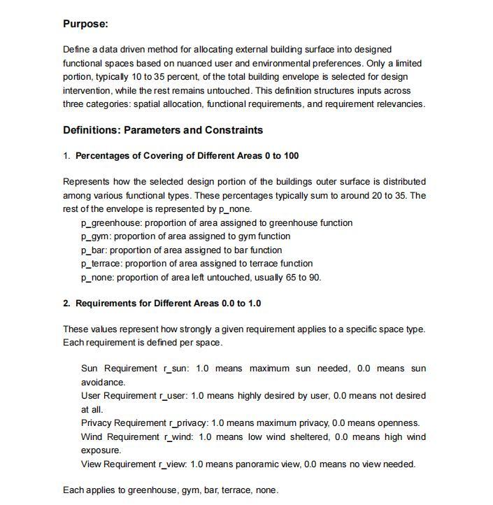
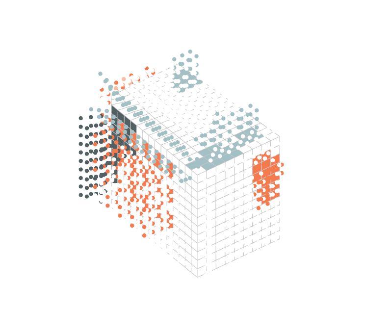
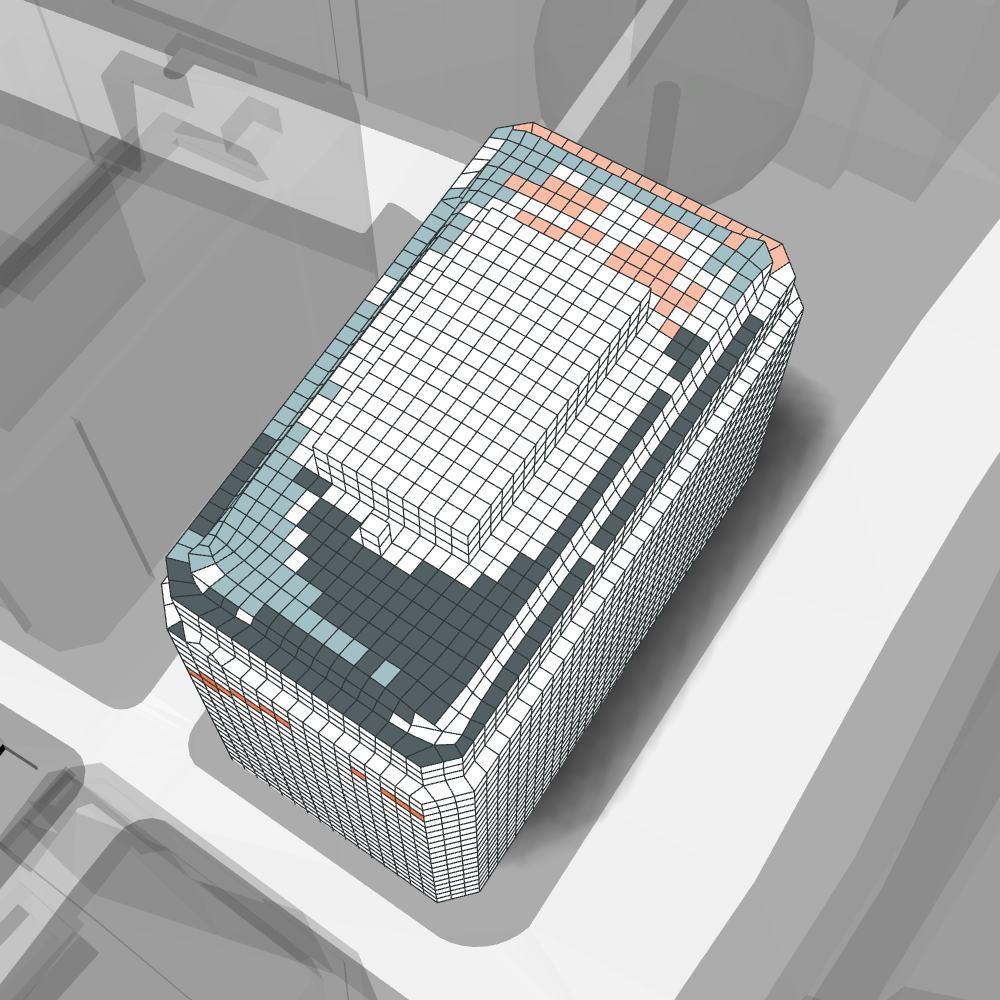
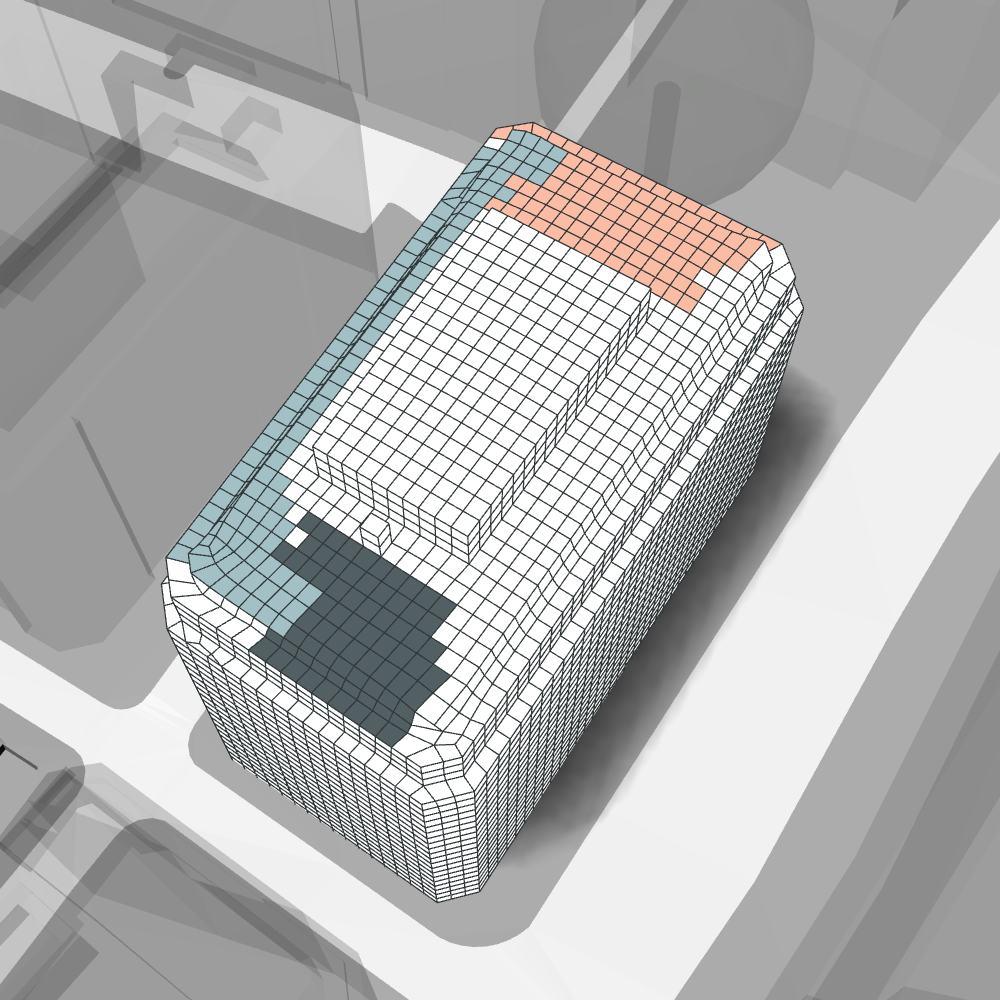
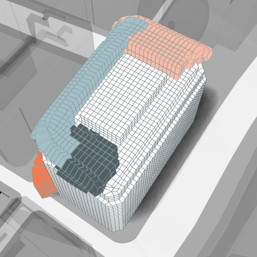
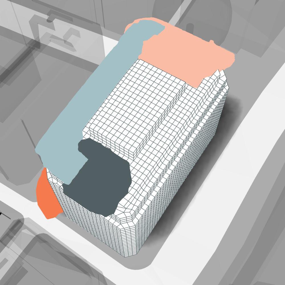
BUILDING SURFACE DISCRETIZATION
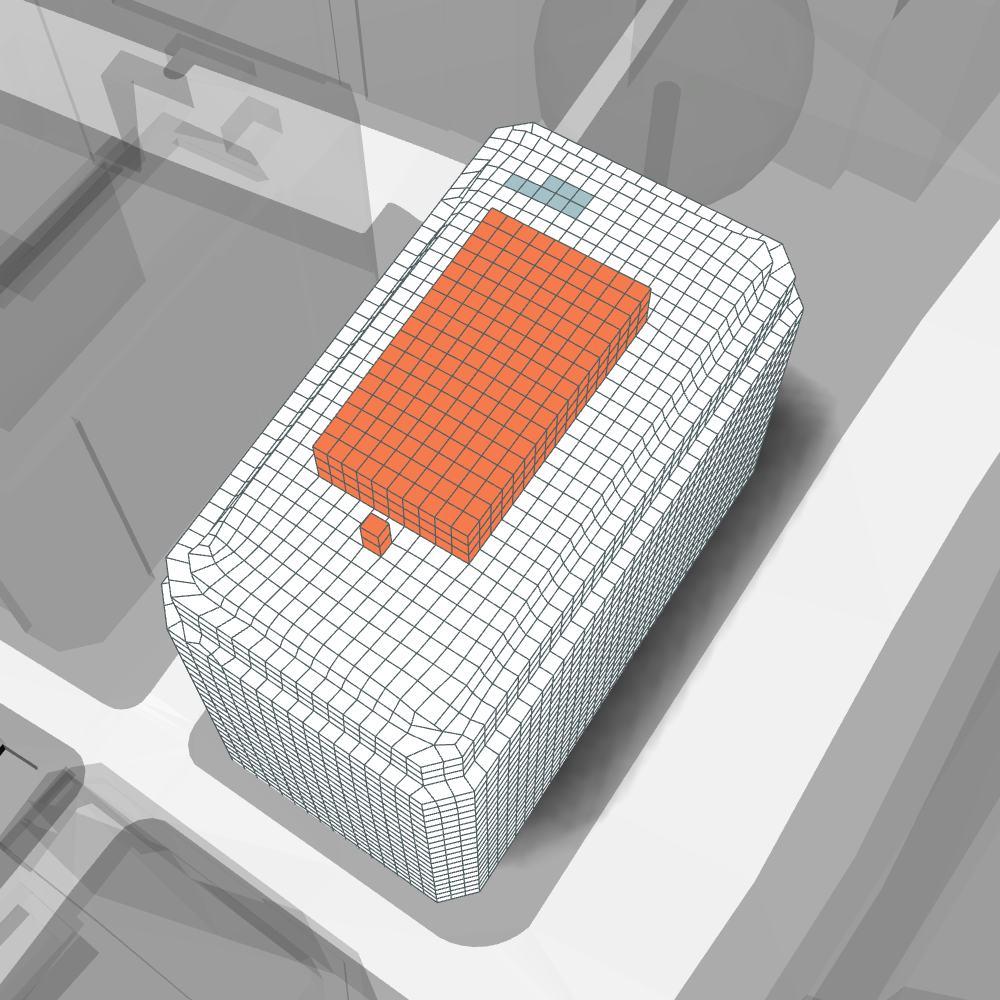
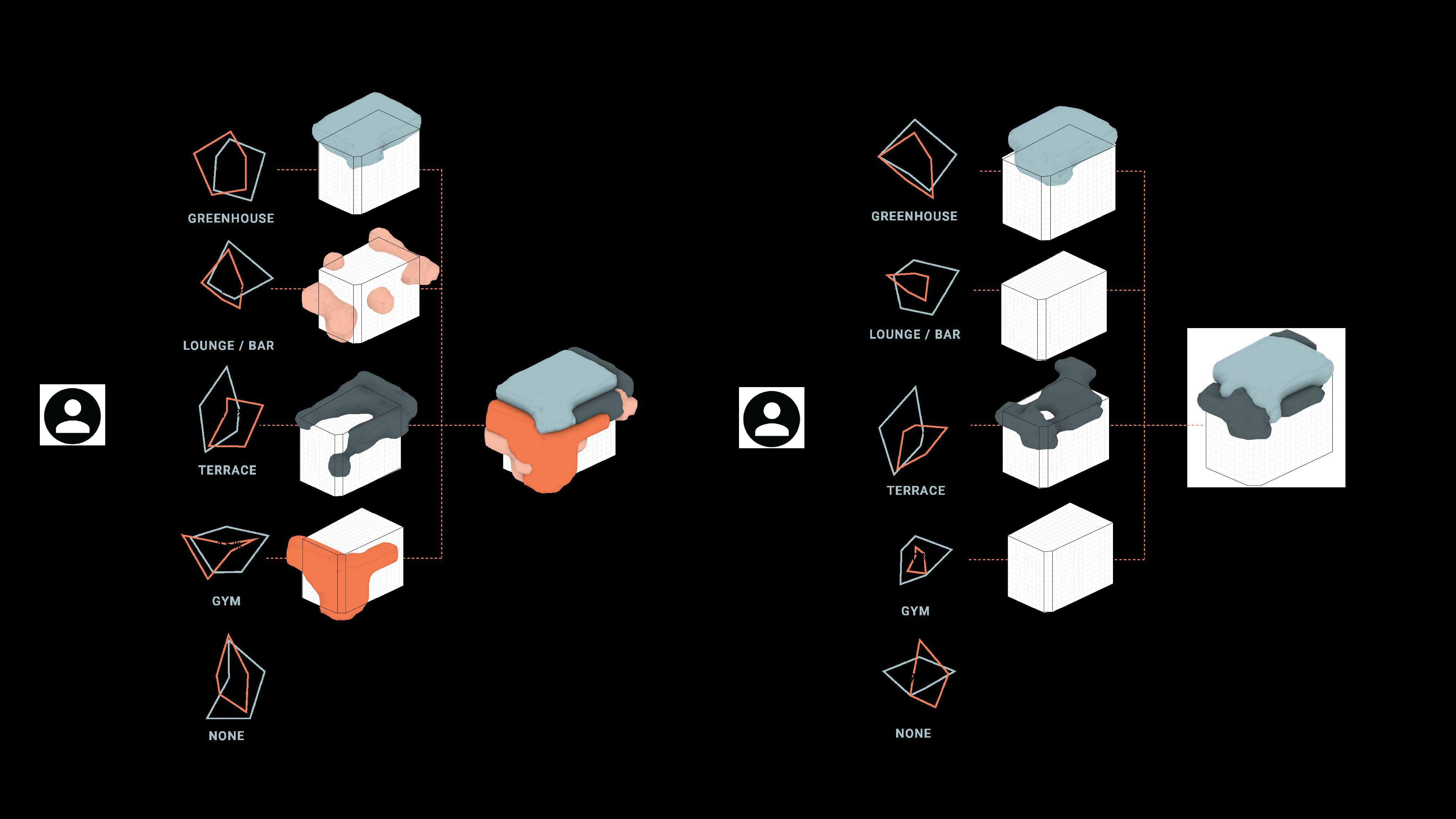
The full set of inputs is represented by two main groups: topological and user scores. The full set is finally used to determine areas on the building where to locate the different uses defined by the user.
FINDING VIABLE AREAS
While the environmental analyses are always the same for one building, , even on the same building. user preferences can change depending on the users inputs leading to different results every time
UNIQUE USER DRIVEN AREAS
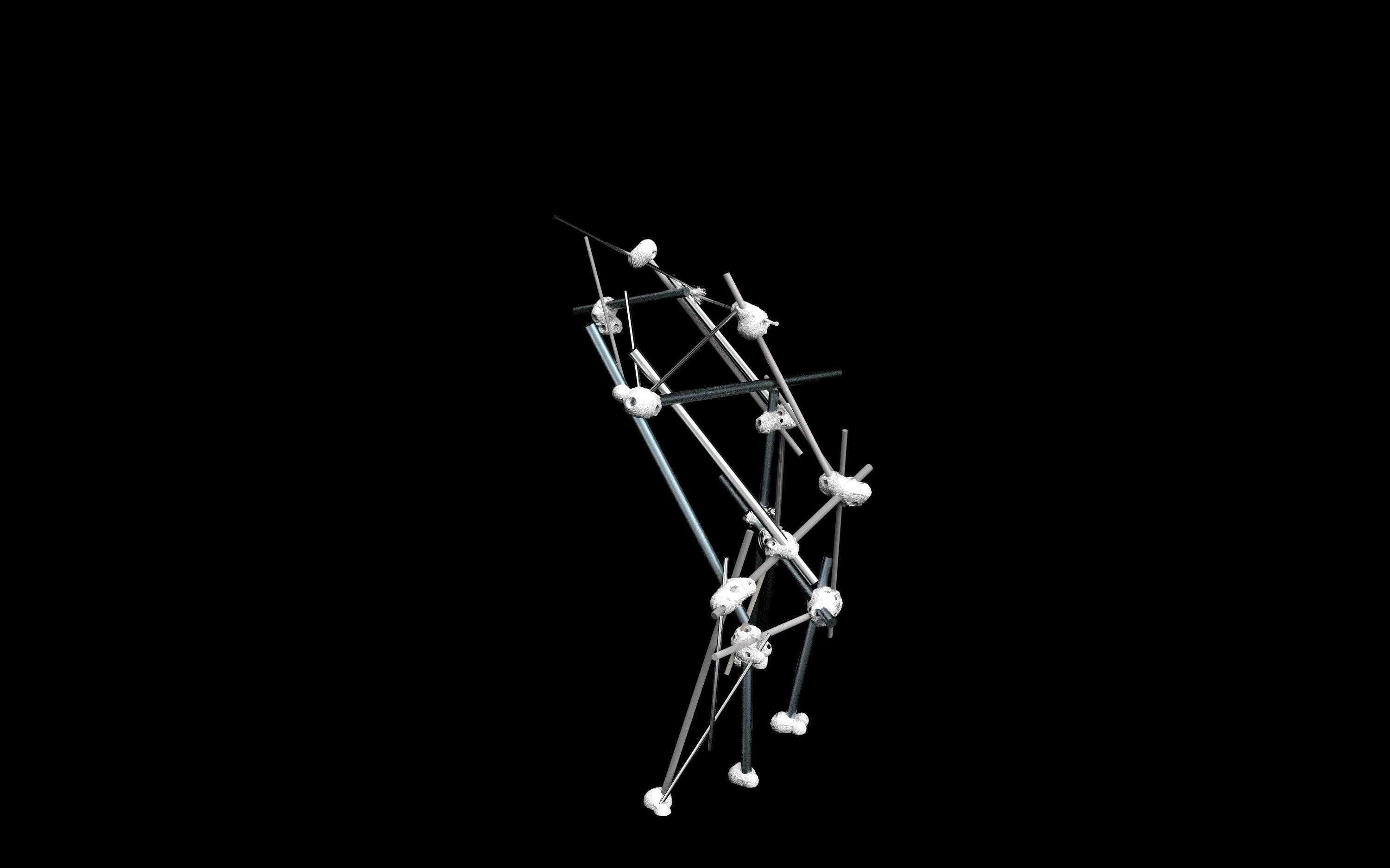
STRUCTURE GENERATION
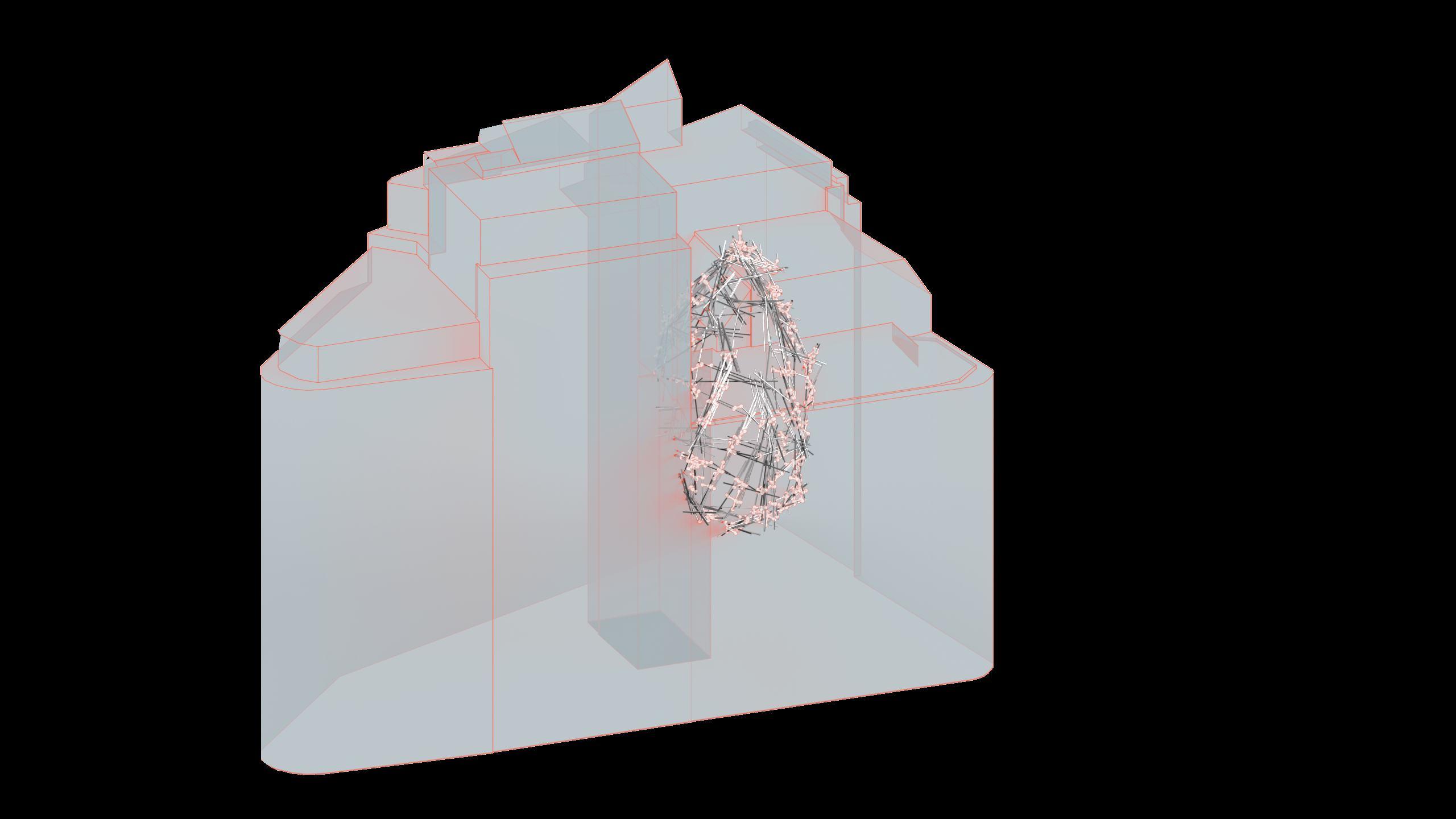
This chapter , a computational design workflow that translates sitespecific parameters into optimized, buildable forms using reclaimed materials.
The process integrates parametric design with material database matching, the system maximizes reuse, minimizes waste, and produces highly efficient, context-specific architectural structures—seamlessly bridging digital precision with sustainable fabrication. summarizes automated structure generation pipeline geometric analysis, stress mapping, and adaptive algorithmic placement of structural elements, including slabs, stairs, joints, and skins.
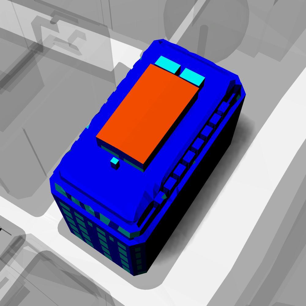
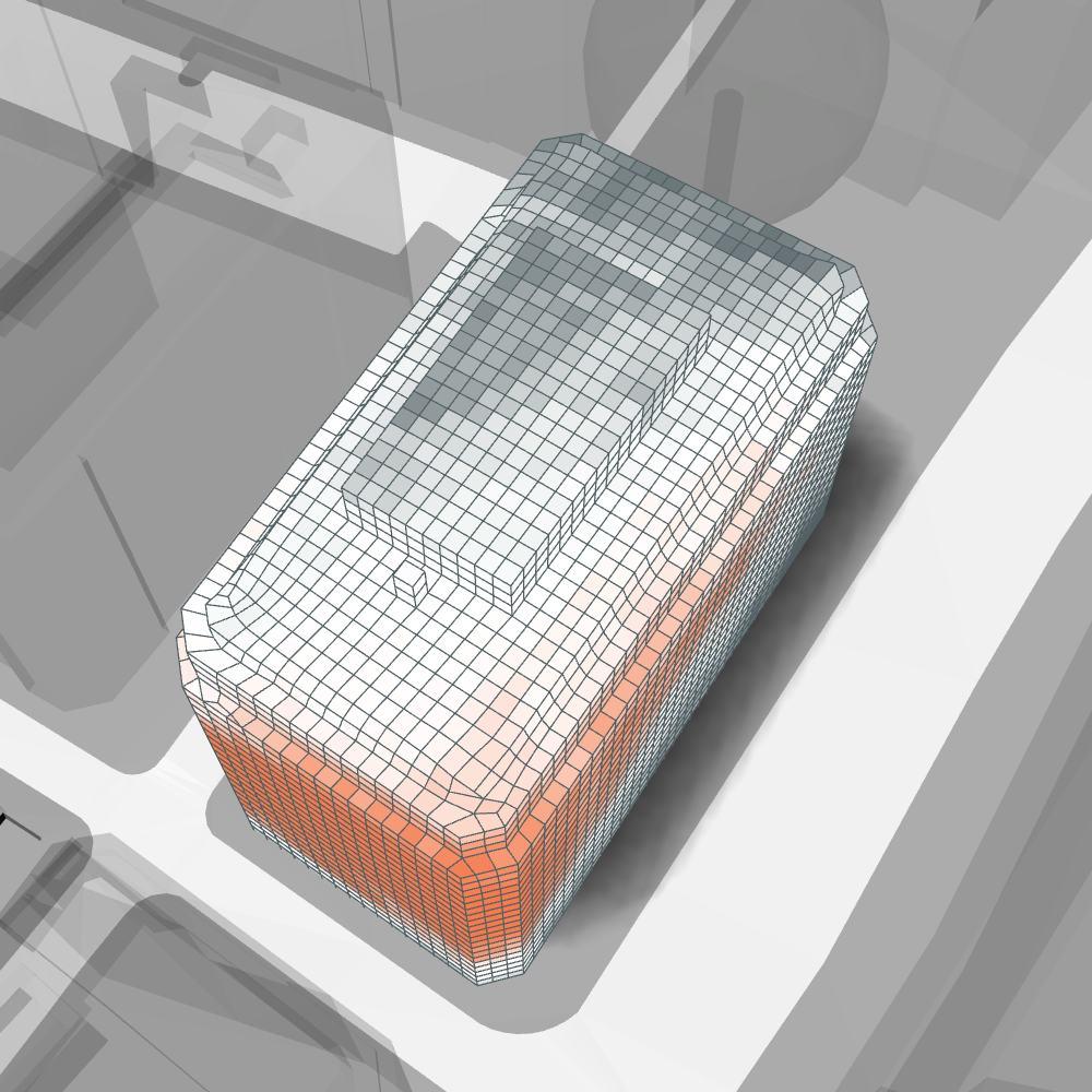
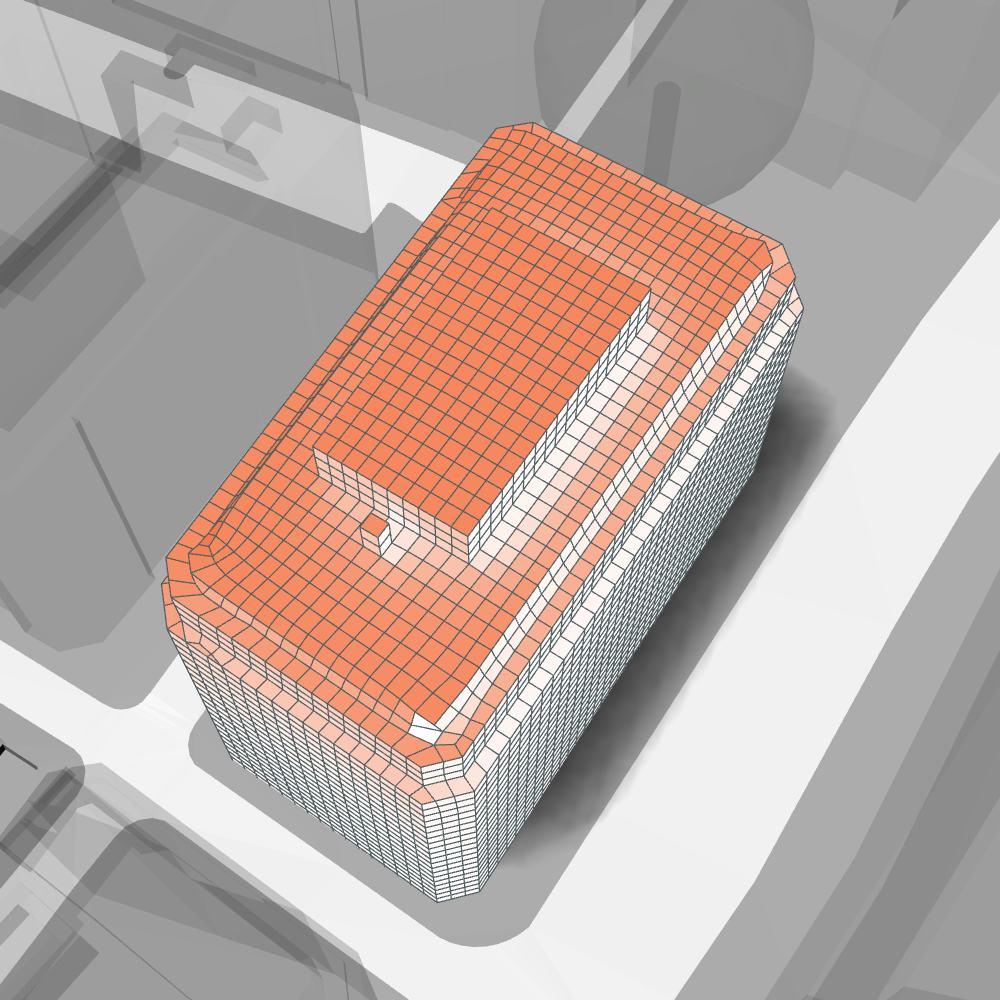
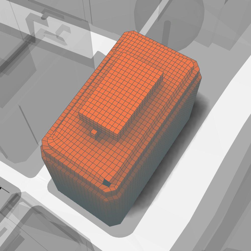
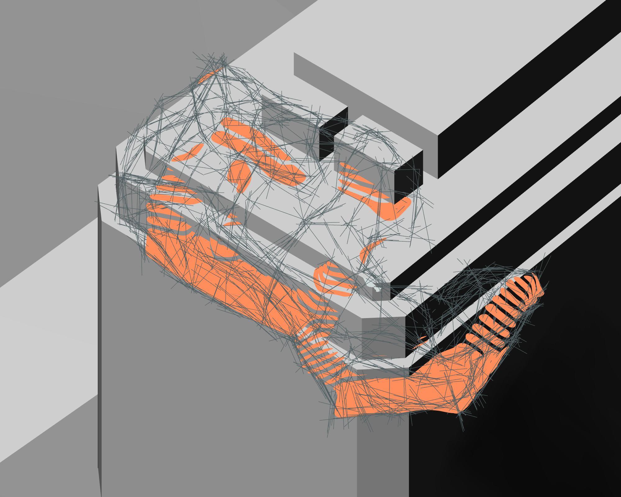
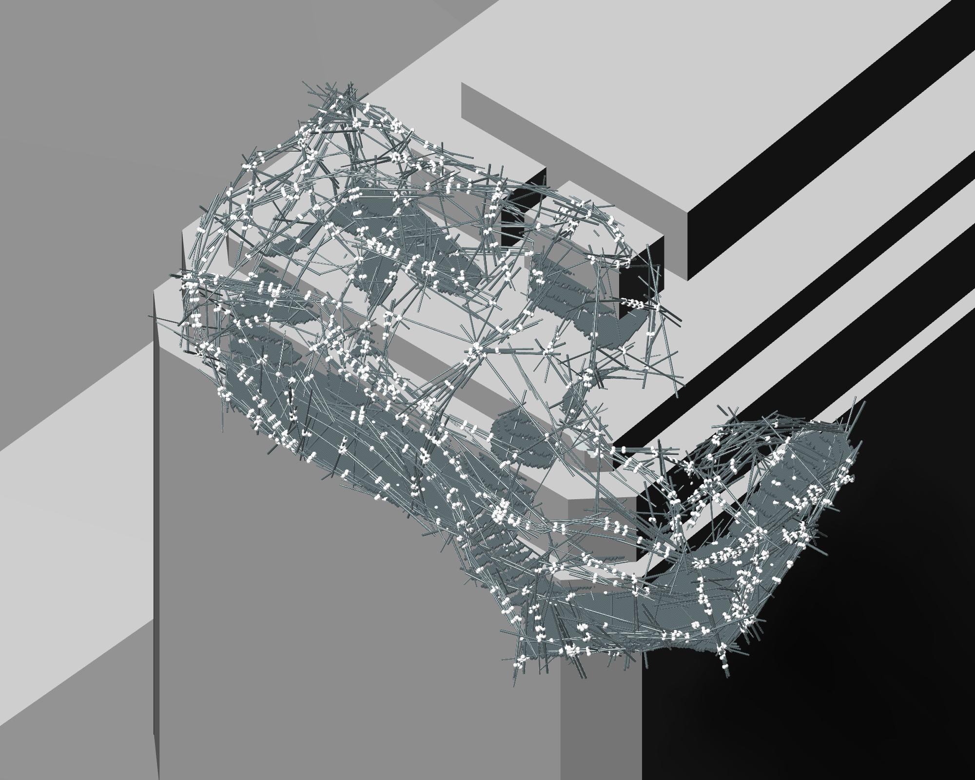
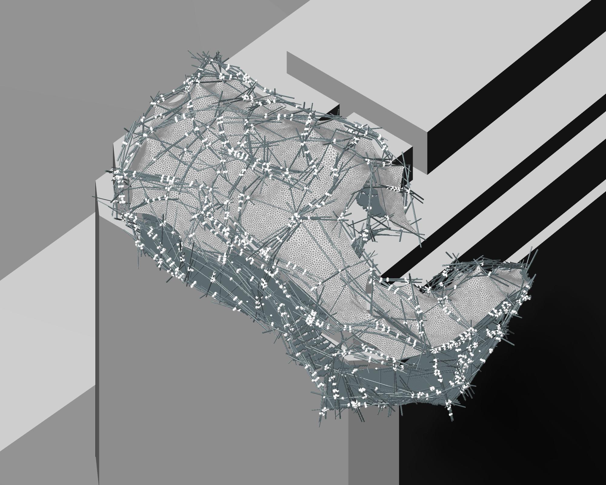
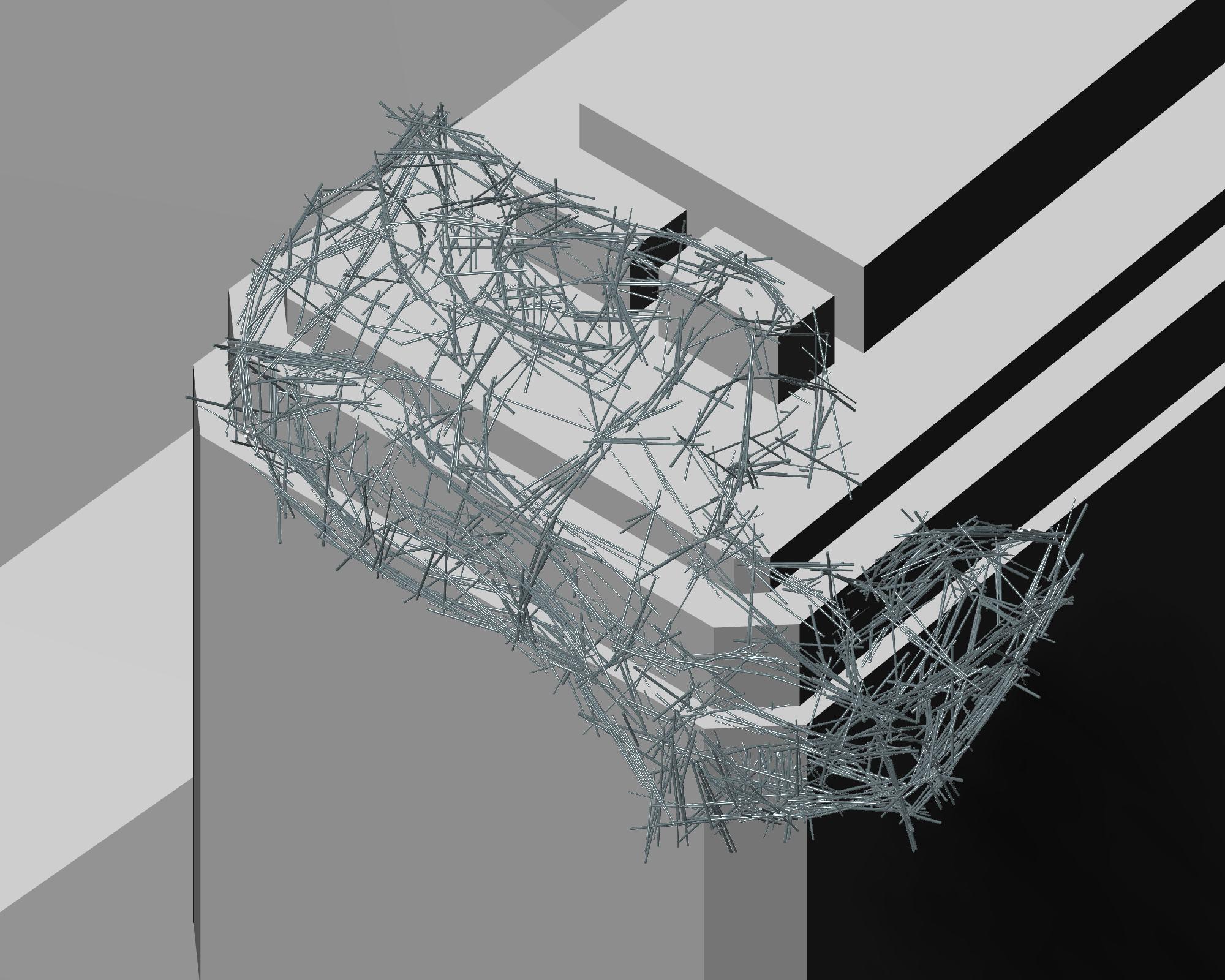
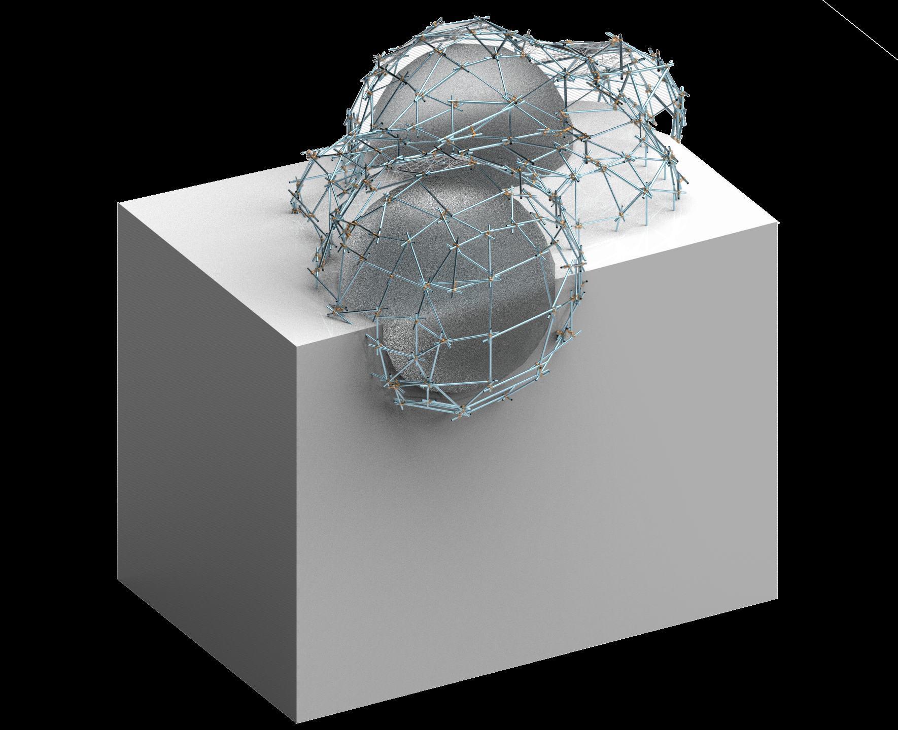
STRUCTURE GENERATION
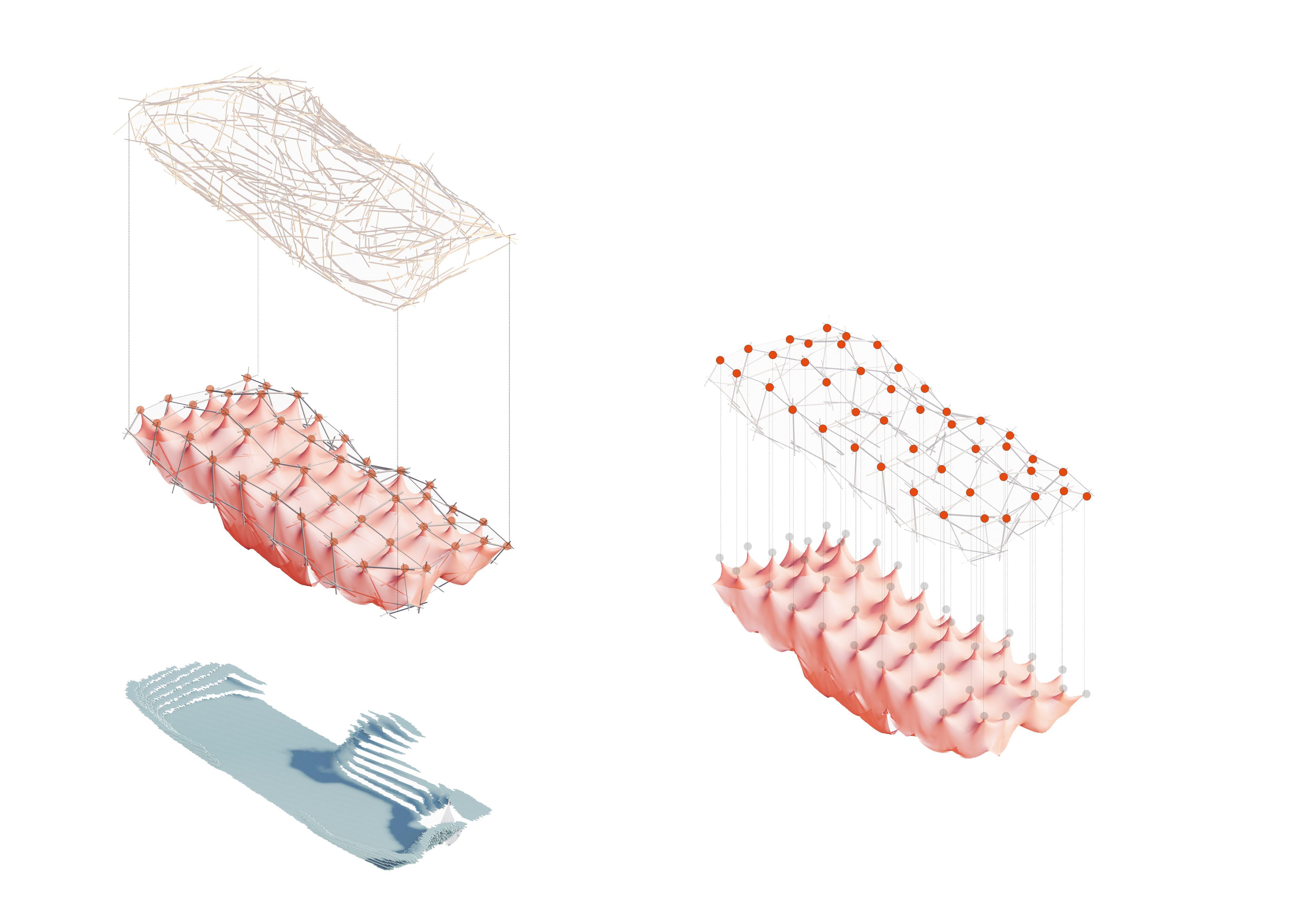
HoloLab’s automated structure generation pipeline
This diagram outlines , which translates site-specific inputs into optimized, buildable forms using reclaimed materials. Beginning with a base mesh and analysis of contact areas, the system generates a heatmap to guide geometric refinement.
Refer to appendix pg. 127-129 for more content.
STRUCTURE GENERATION
Stress lines and reinforcement branches inform structural decisions, while pipes are assigned based on cosine similarity, ensuring material fit and efficiency.
Additional layers such as slabs, stairs, joints, and skins are then generated algorithmically, culminating in a contextual, circular final structure.
This workflow combines architectural intelligence with computational precision, maximizing reuse and minimizing waste.
Refer to appendix pg. 134-139 for more content.
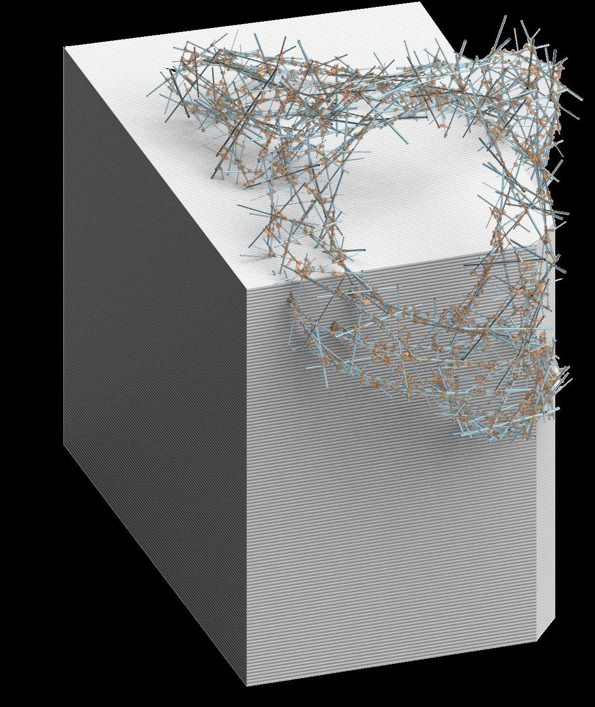
REINFORCMENTS BRANCHES BASED ON STRESS LINES
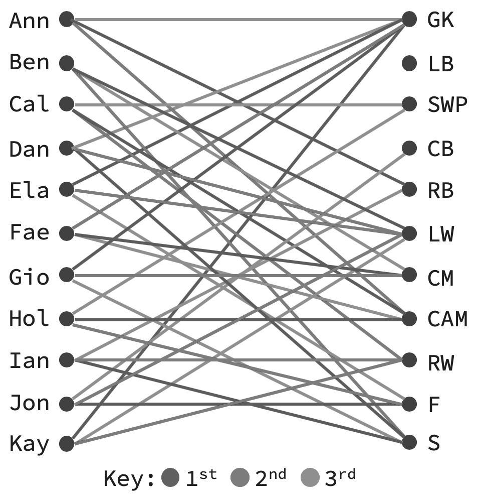
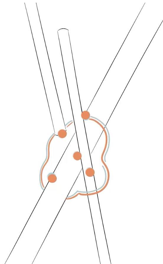
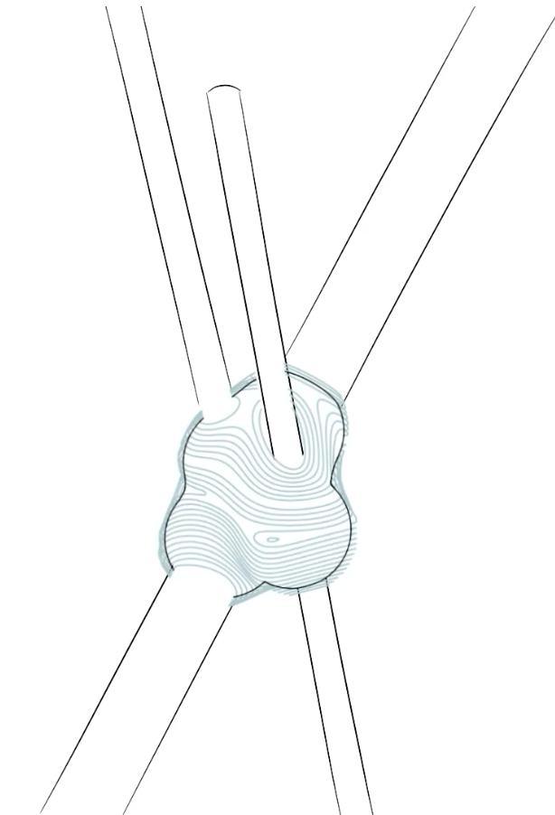
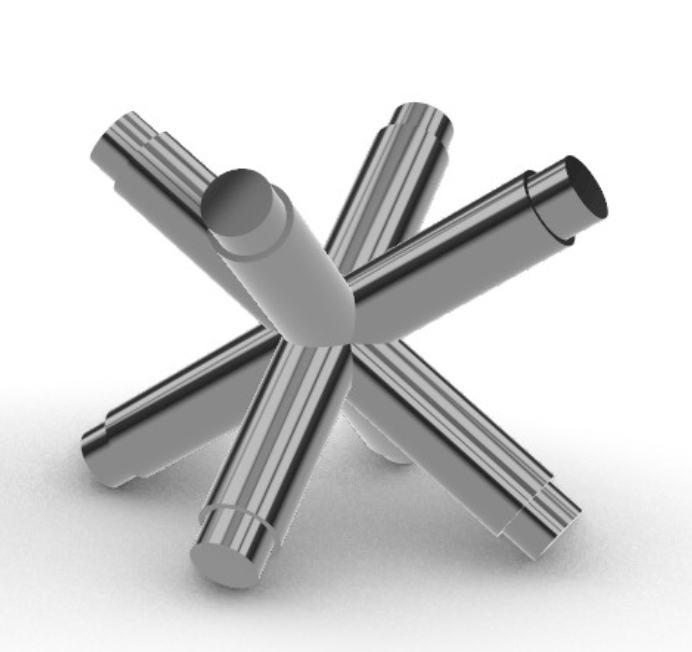
PIPES ASSIGNMENT BASED ON COSINE SIMILARITY
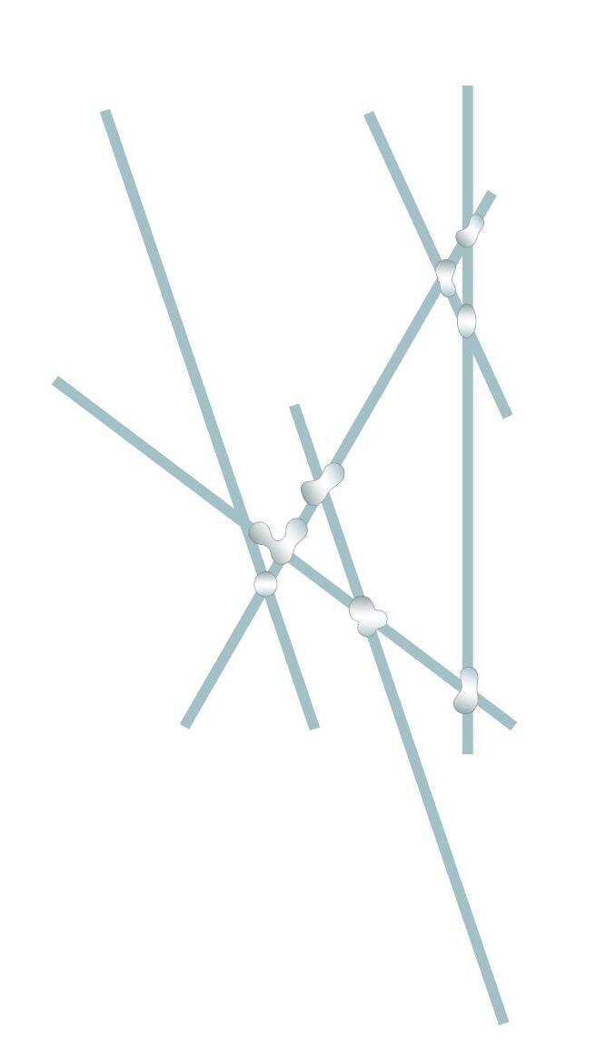
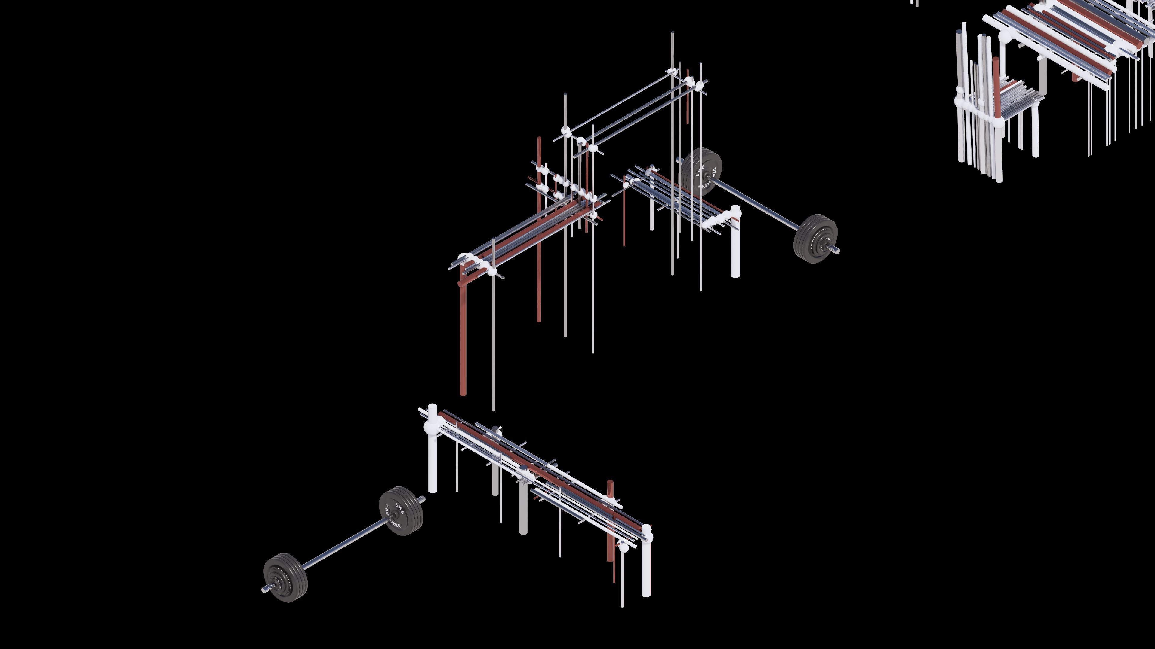
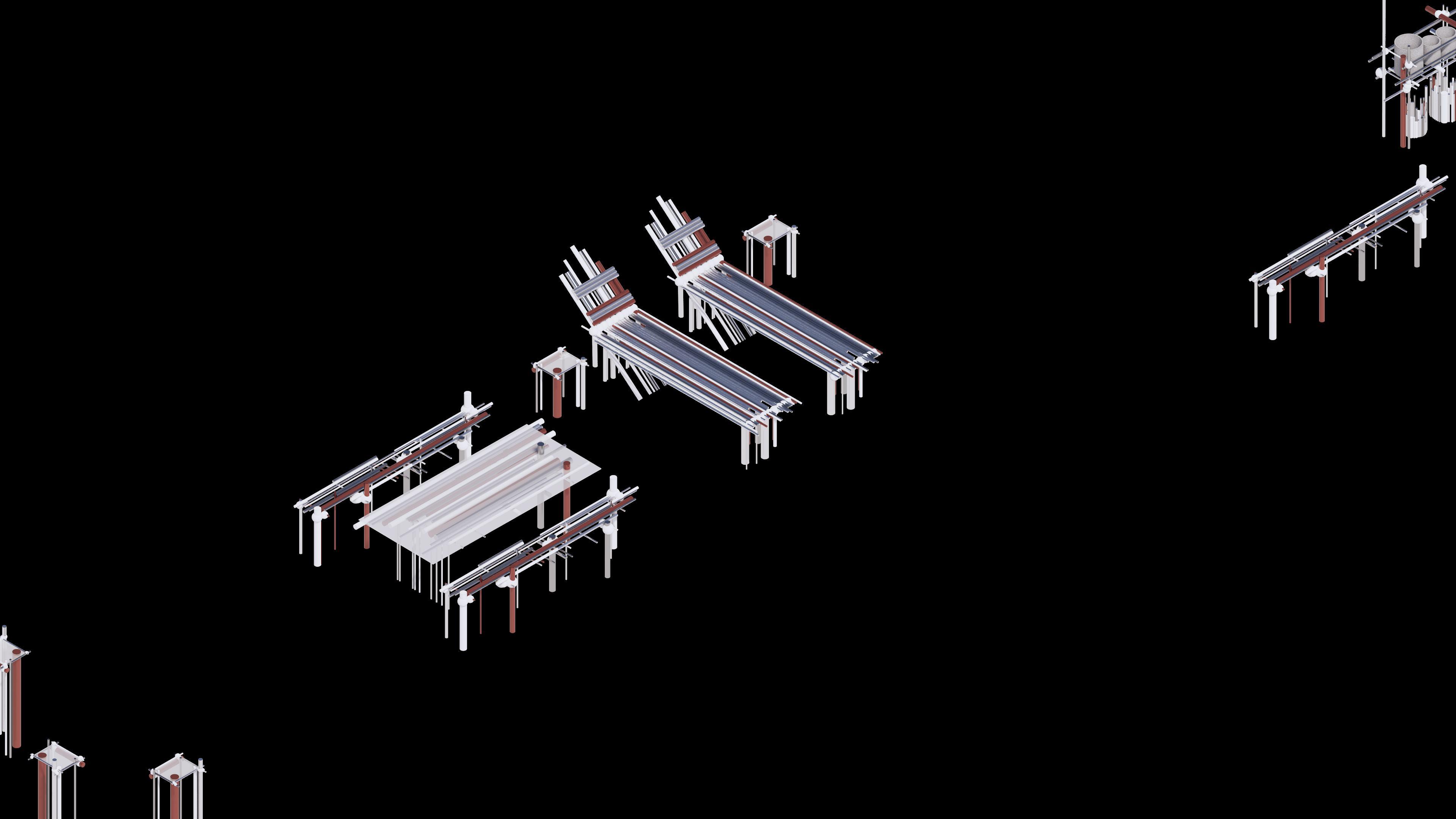
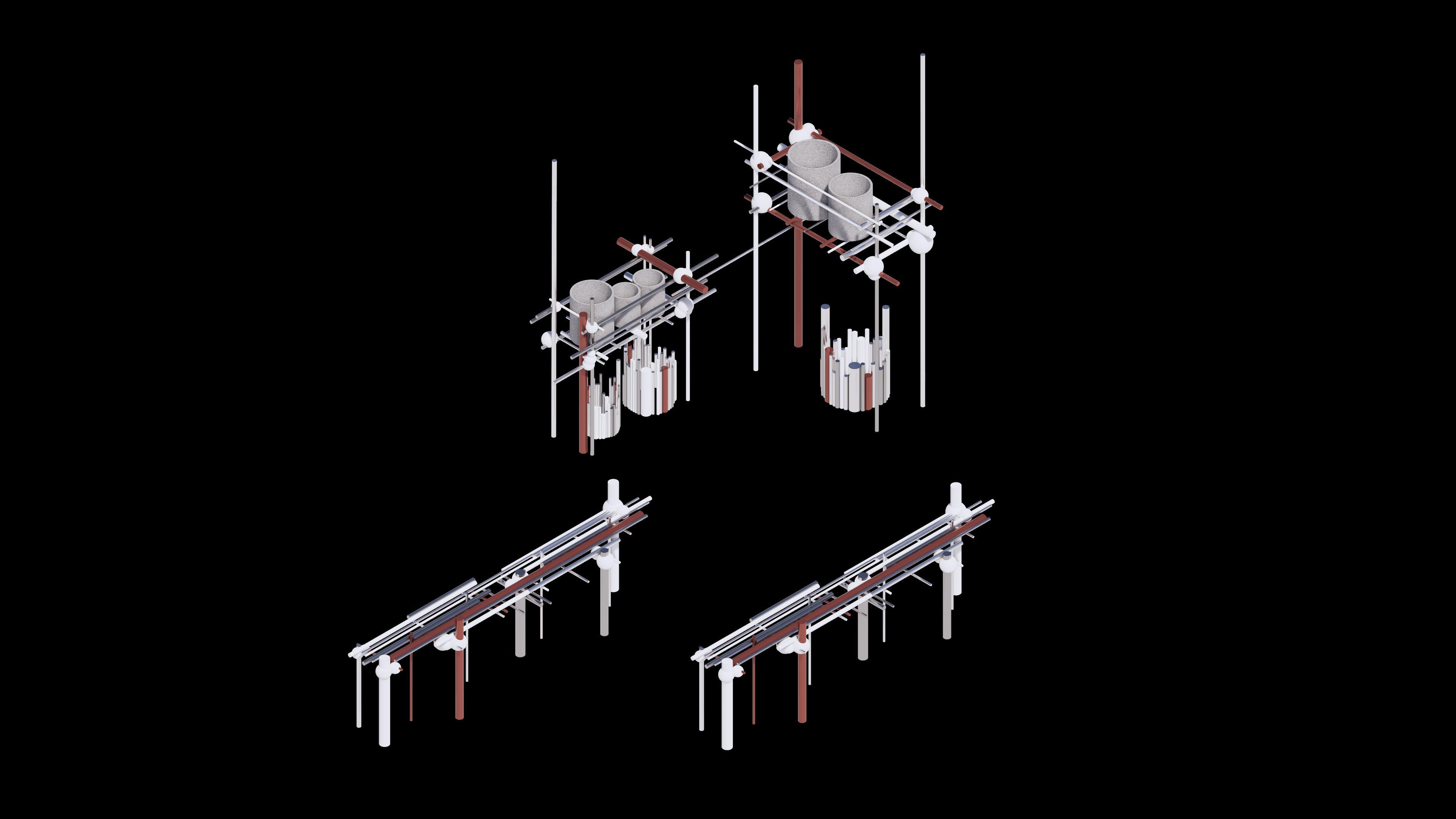
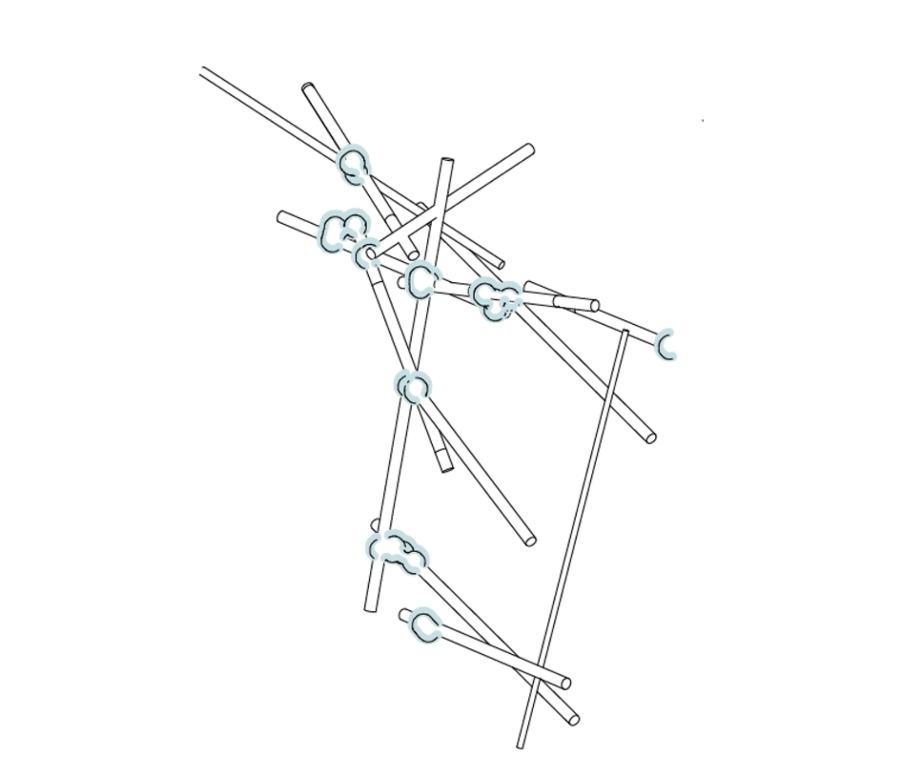
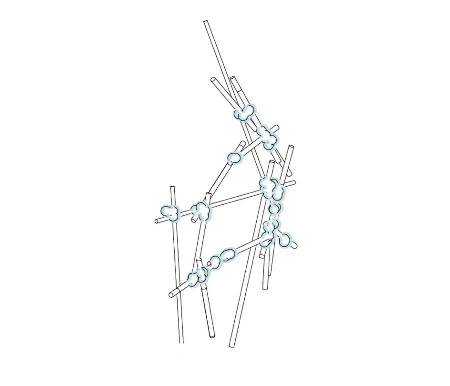
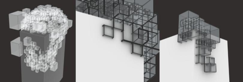
AGGREGATION STUDIES
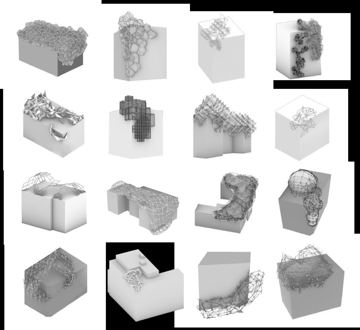
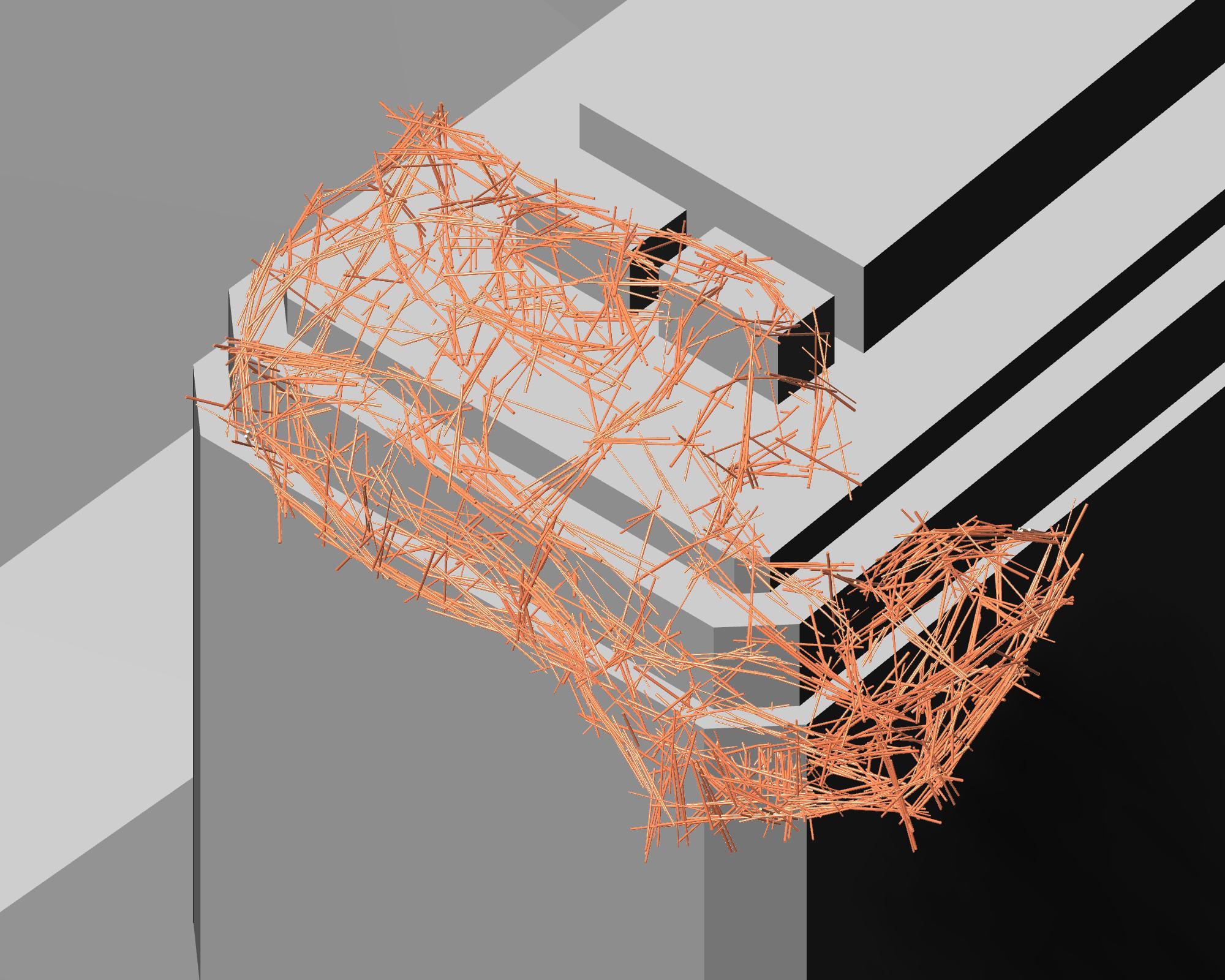
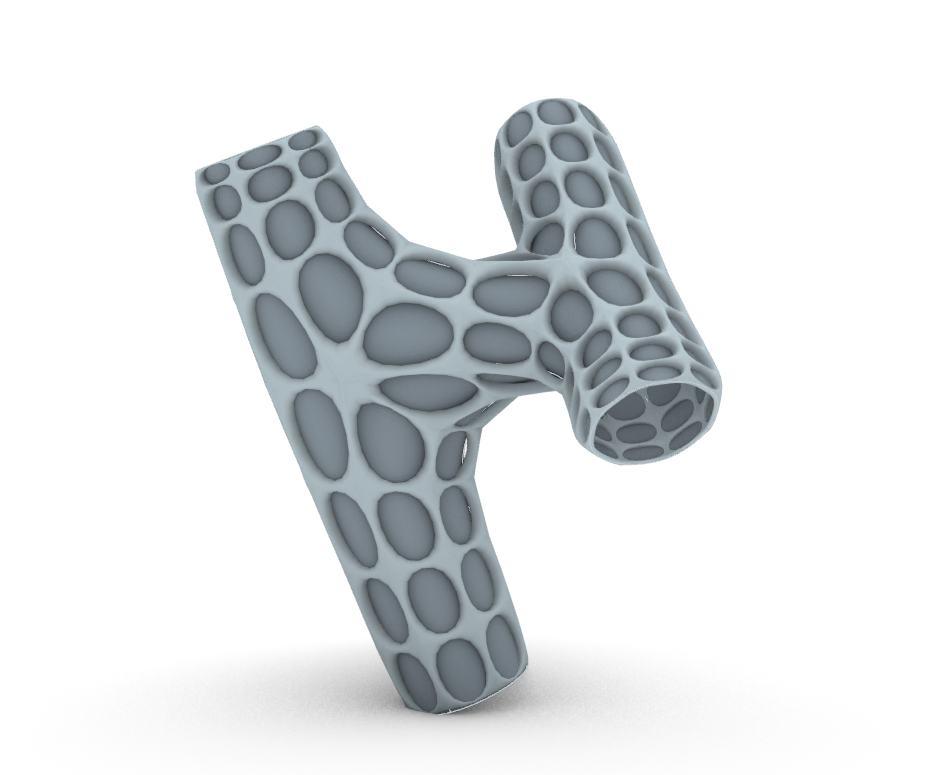
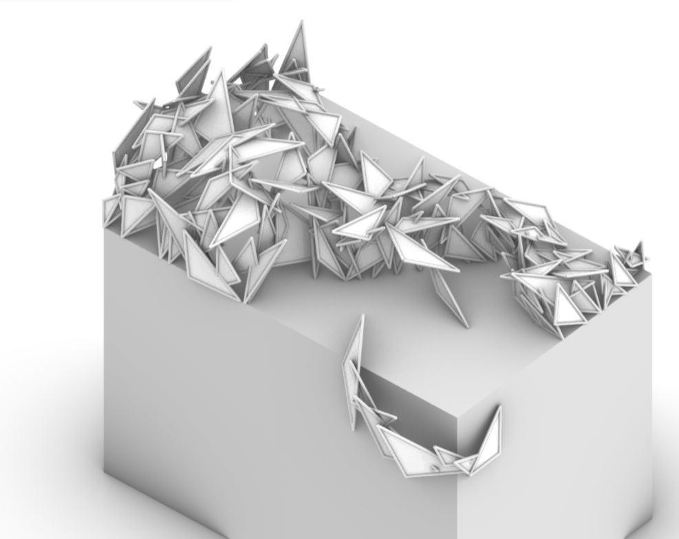
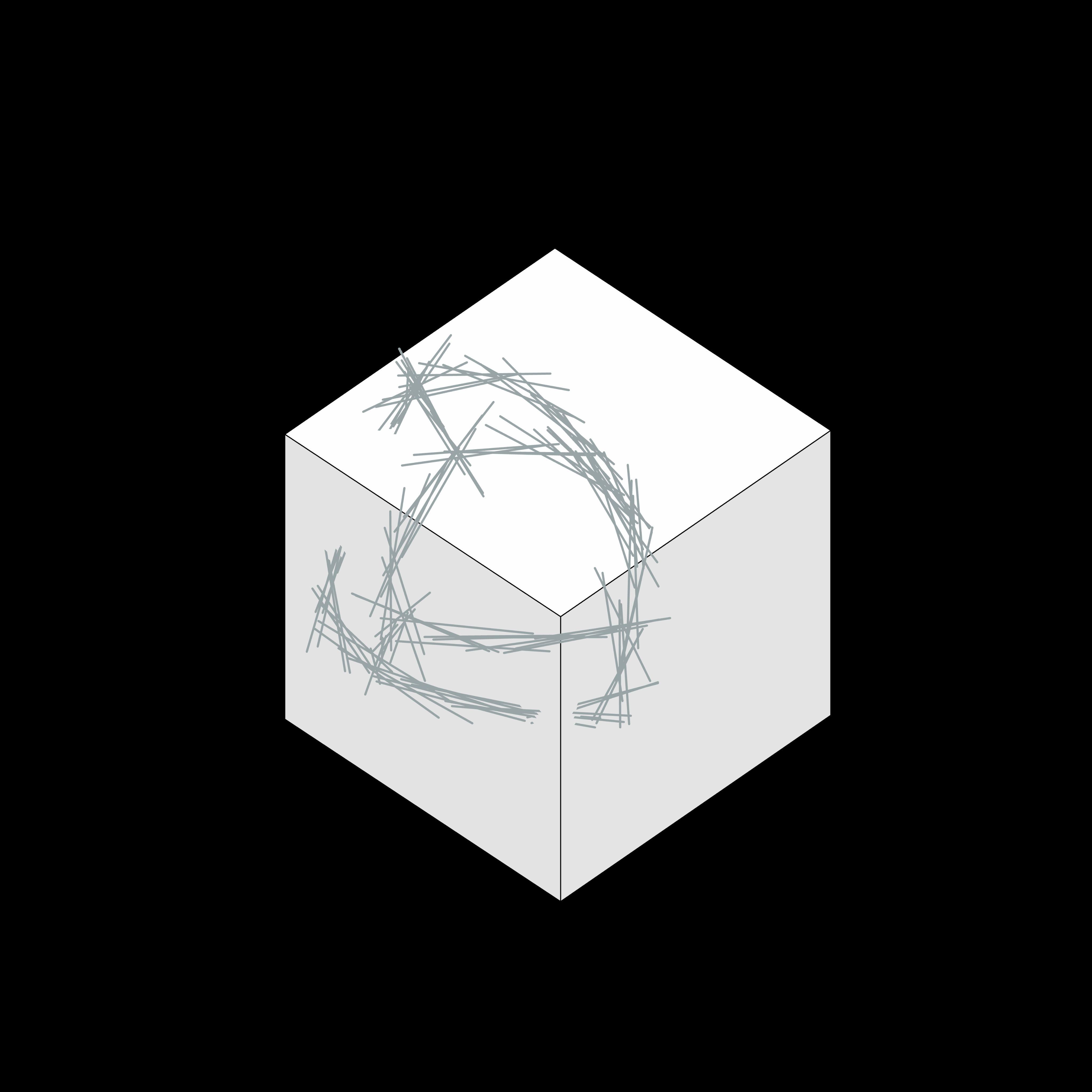
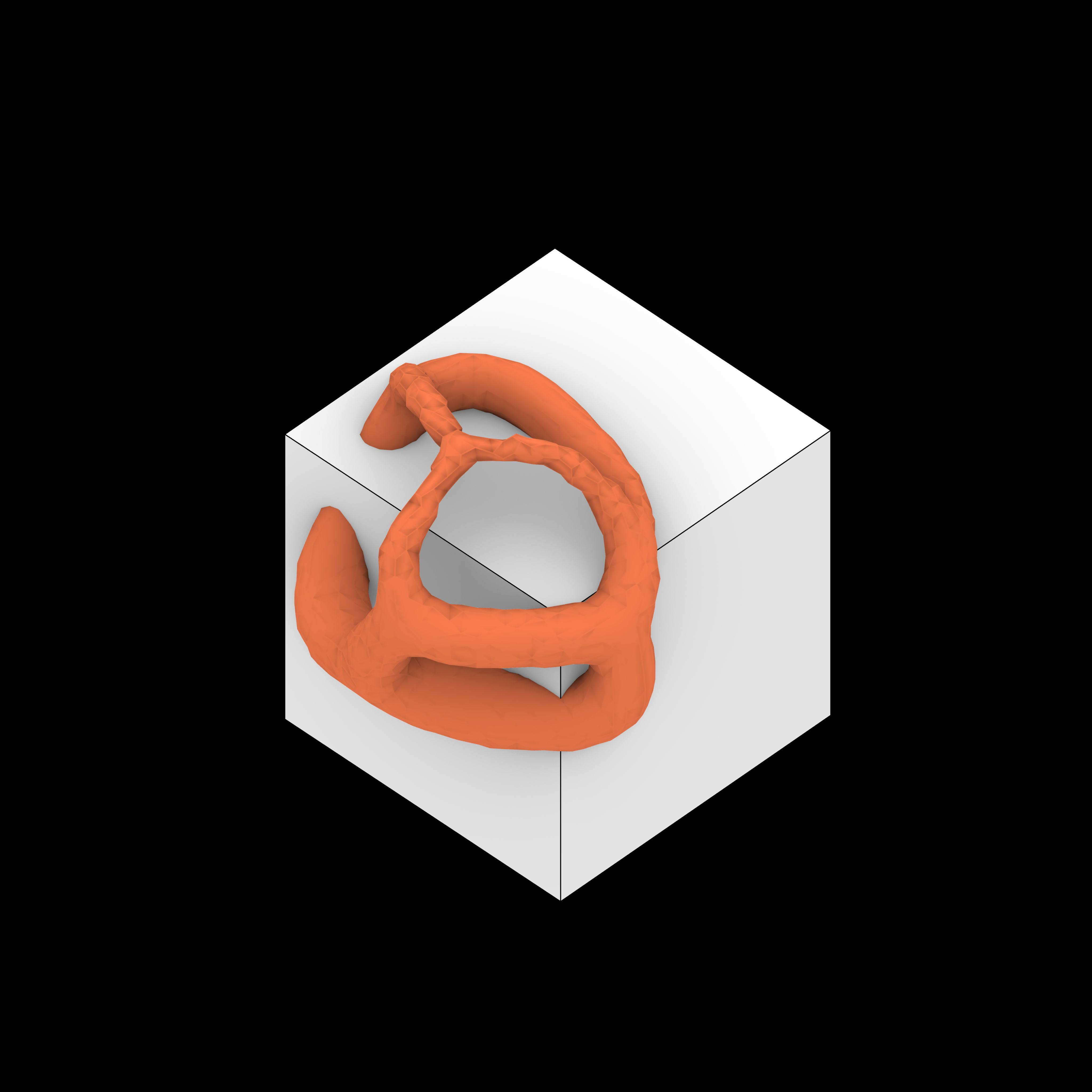
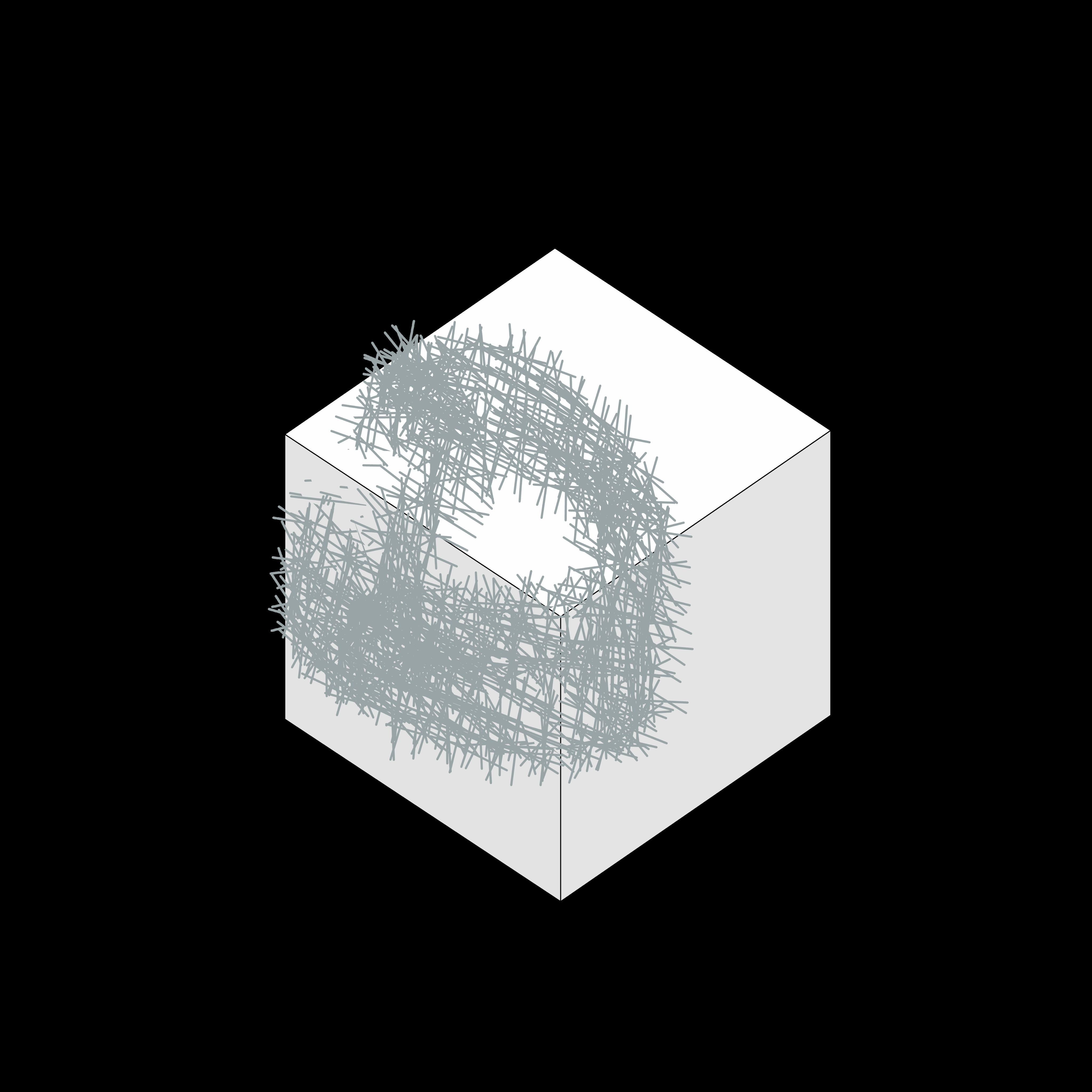
Pipe aggregation options avoiding off cut waste, materials first logic regarding the form finding. have been studied deeply in order to achieve some important goals such as:
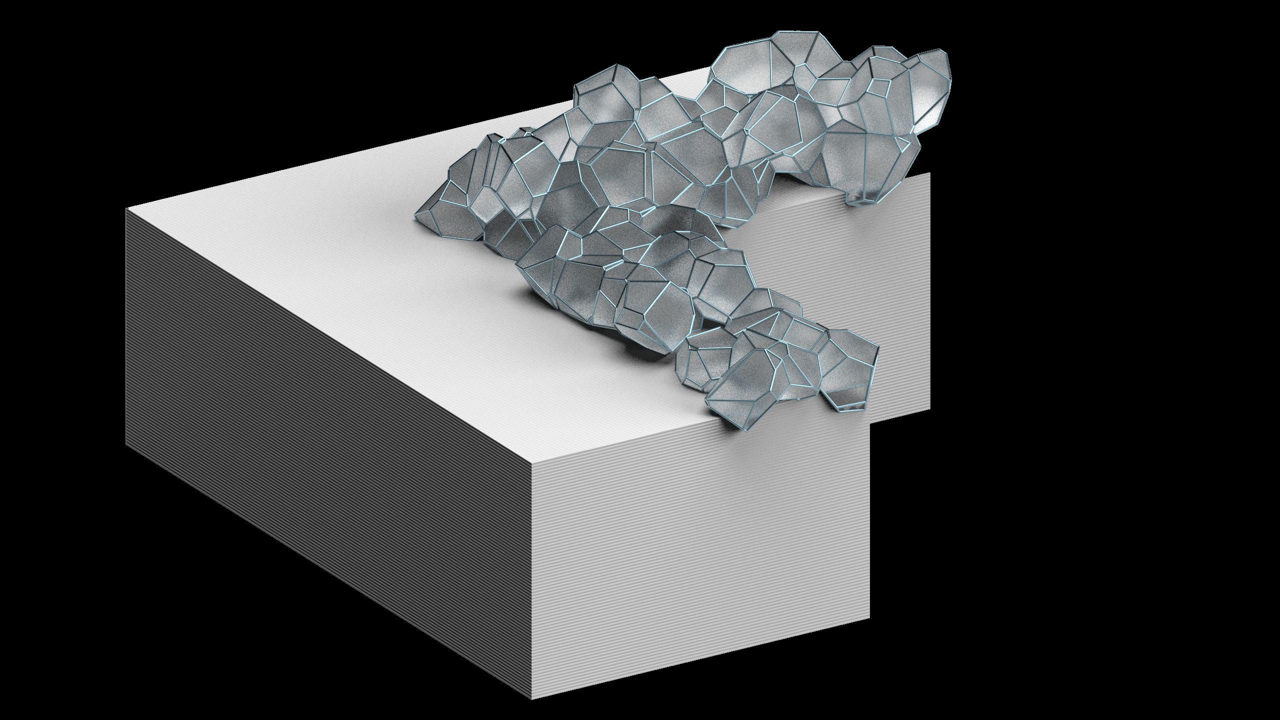
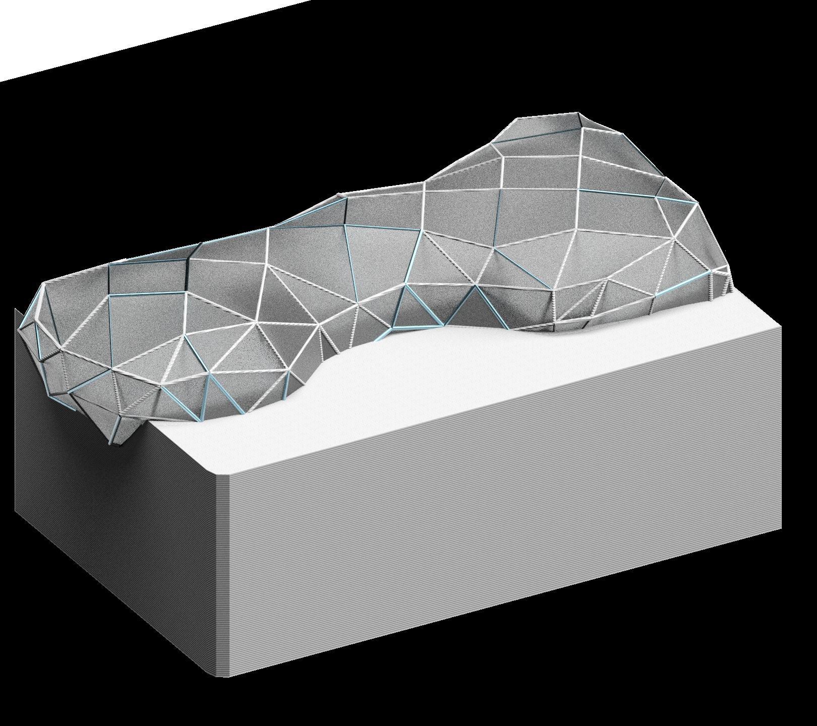
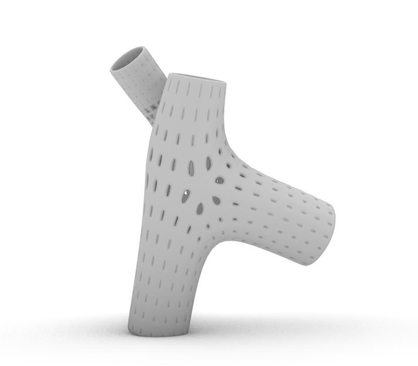
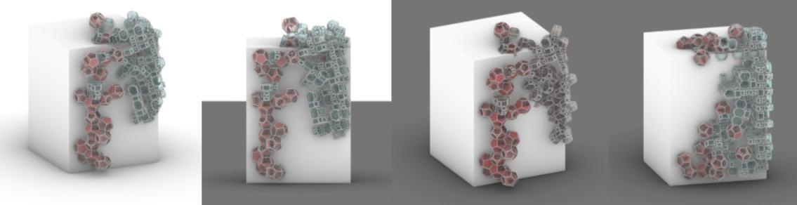
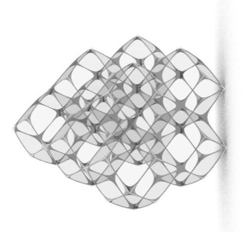
First attempts were Voronoi aggregation. Then space filling solids have been investigated for their capacity of leading to standardized joints. Due to the very large amount of off cuts in such structures we started investigating irregular mesh geometries and others, which can accommodate various lengths, radii, and materials.
Refer to appendix pg. 109-112 for more content.
GEOMETRY TIMELINE
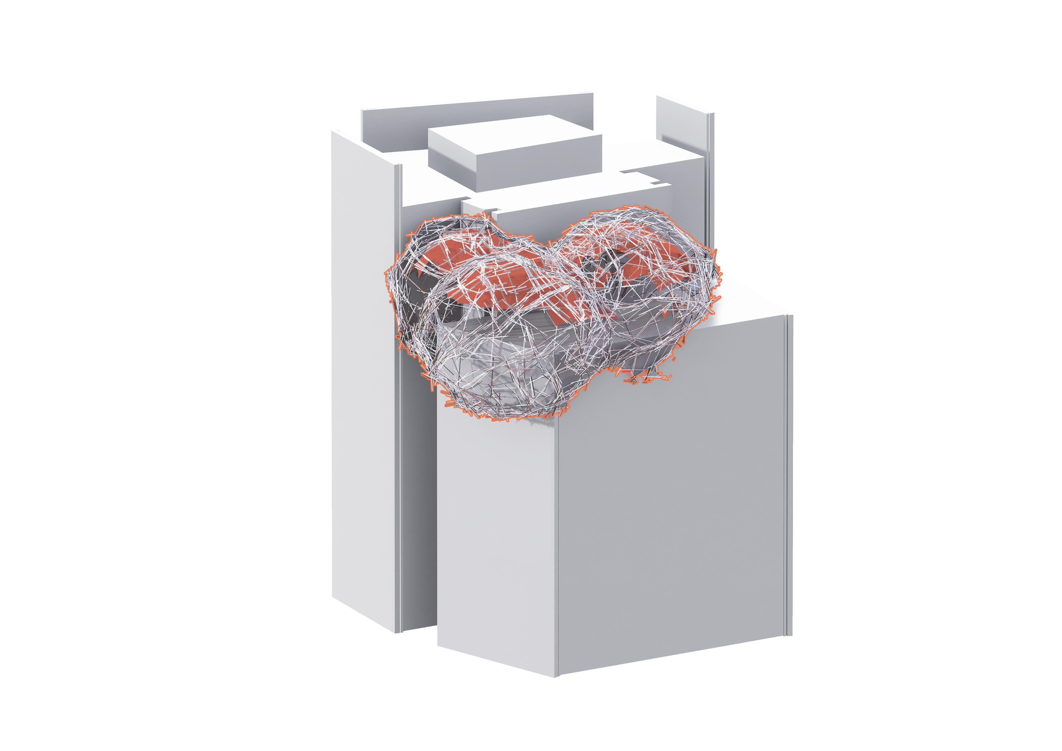
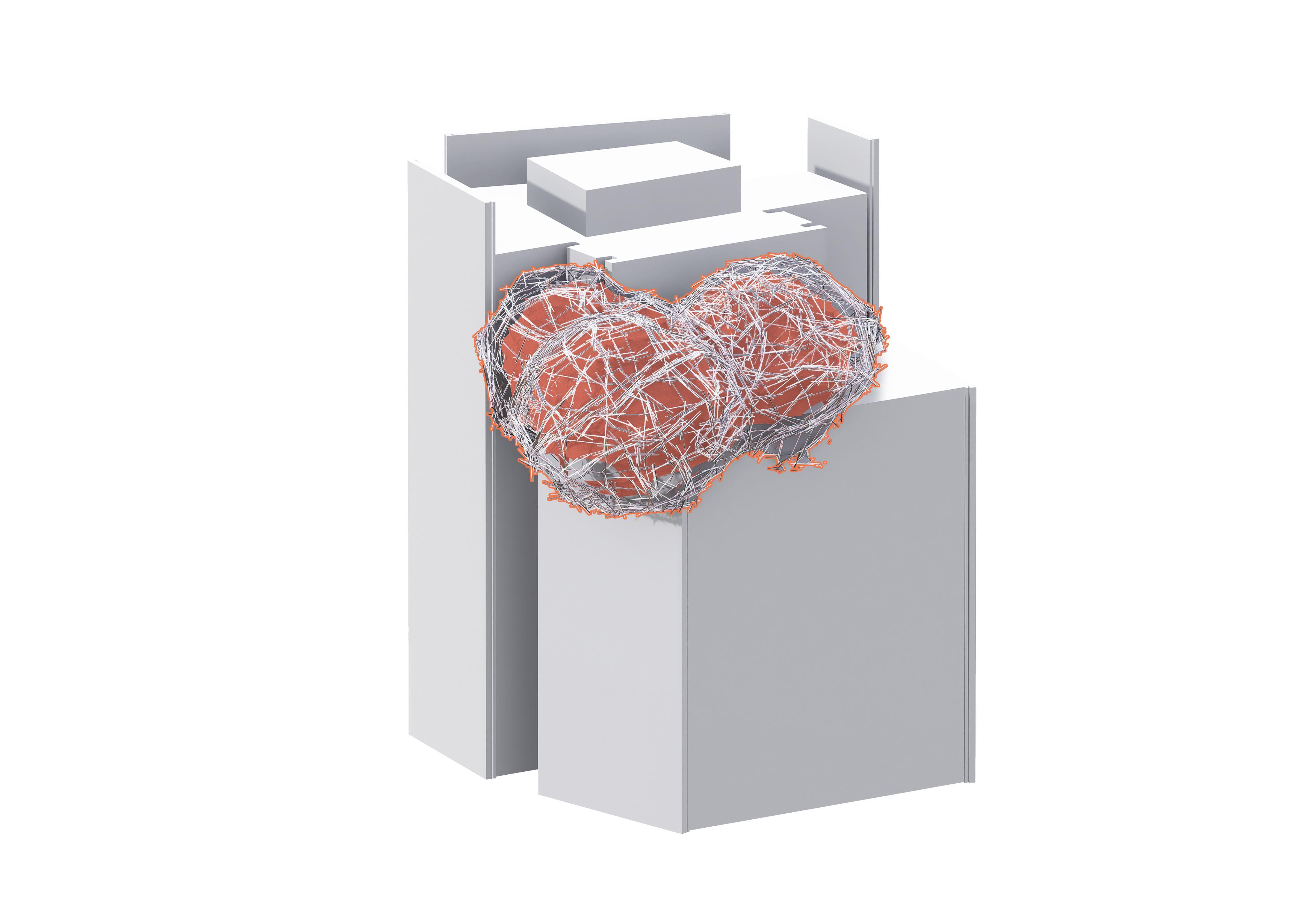
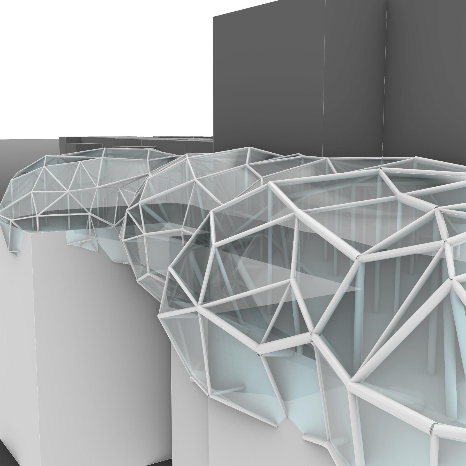
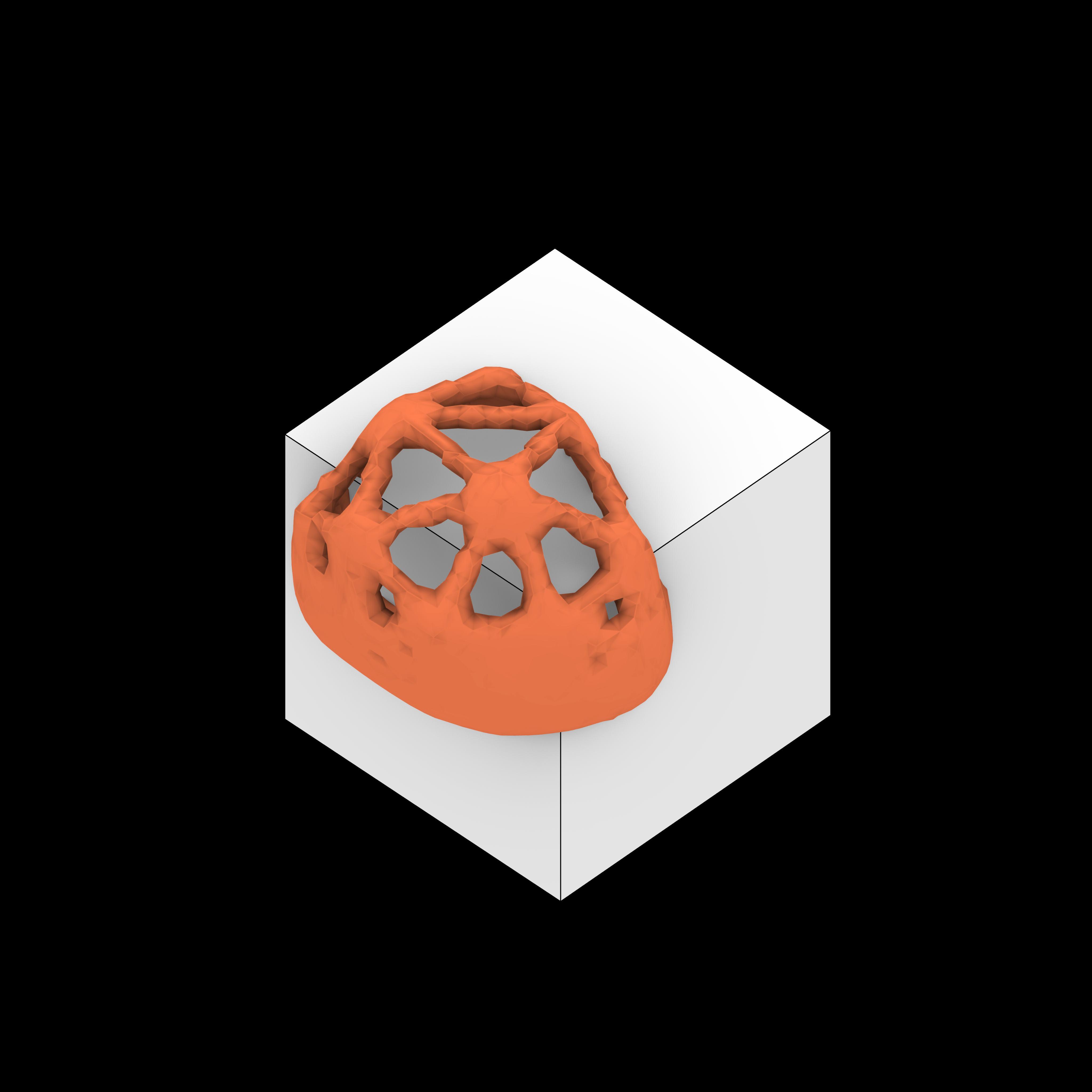
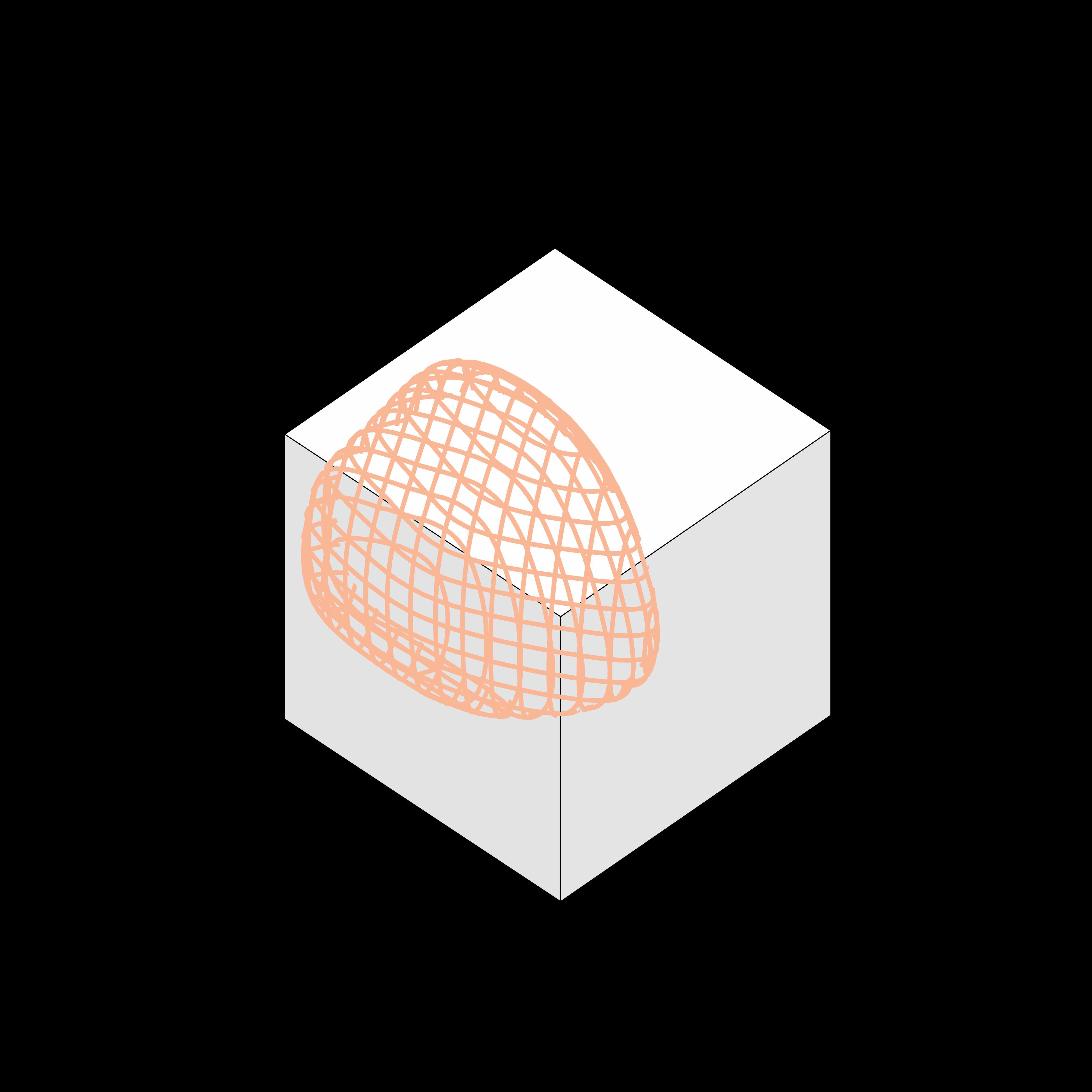
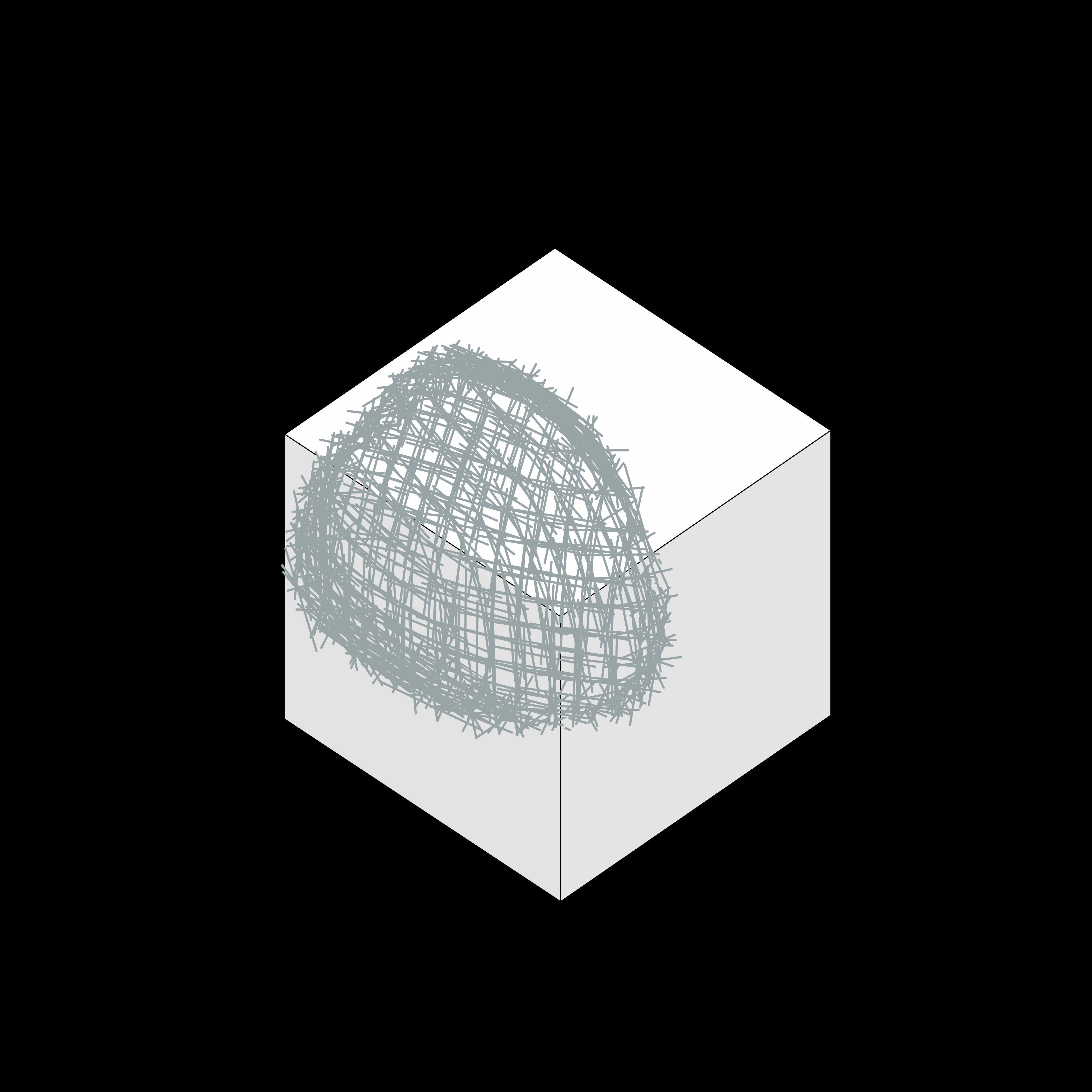
SHRINK WRAP DOME
BETWEEN Structural AXIS AND DATABASE availability PAIRS WITH THE MAXIMUM AVERAGE Galapagos structural configurations to determine the best
Refer to appendix pg. 129 for more content.
PIPES DATABASE
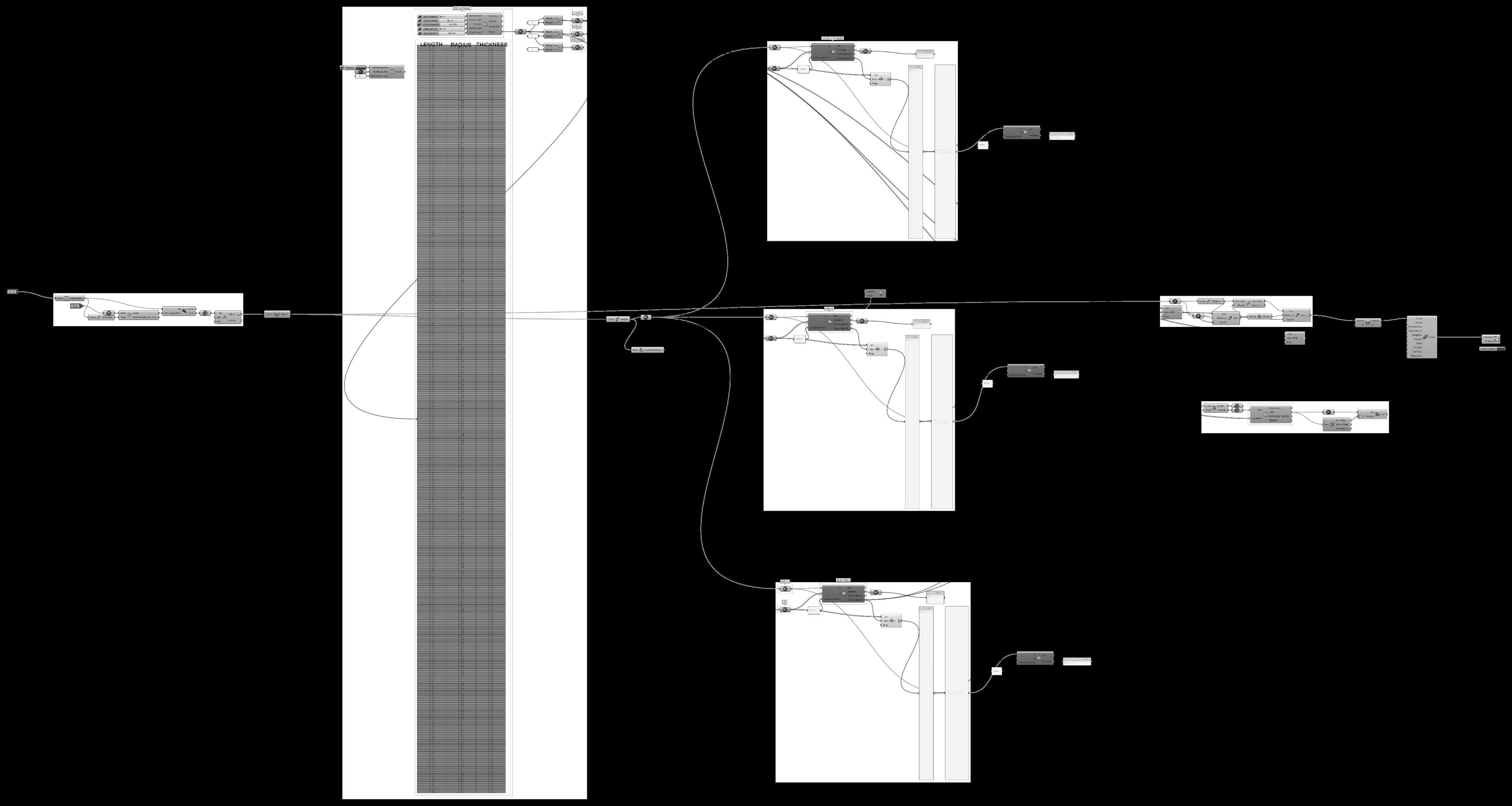
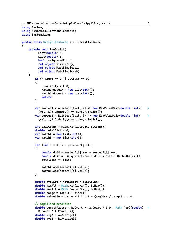
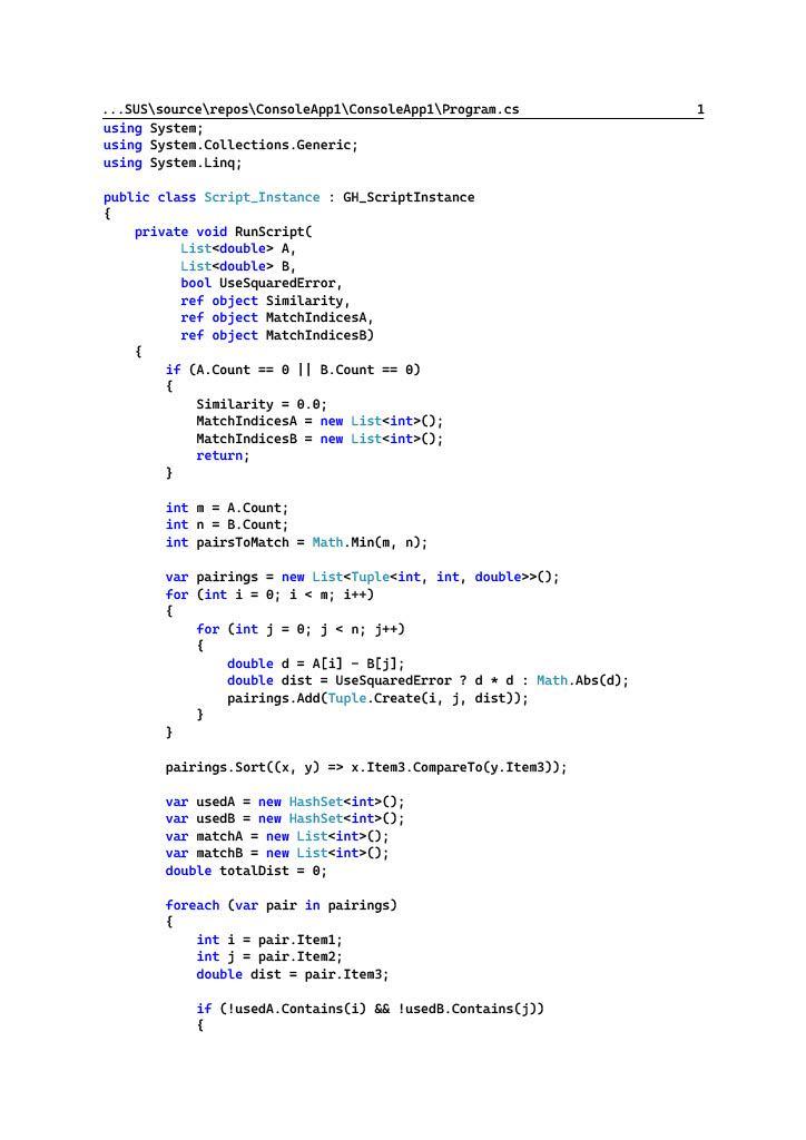
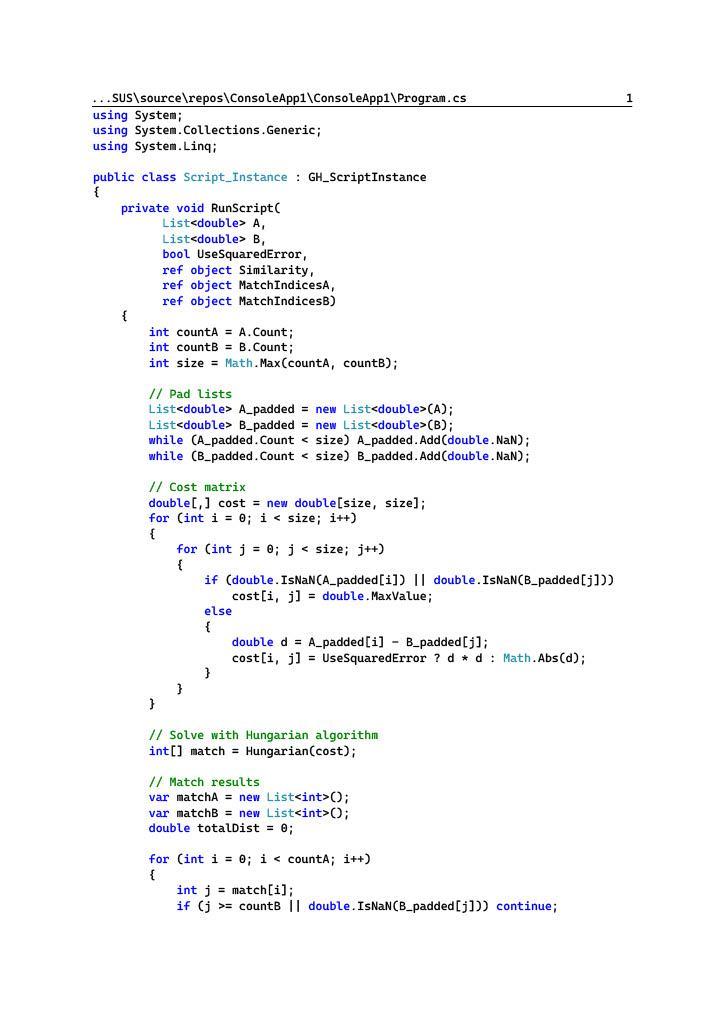
MATCHING ALGORITHM
HUNGARIAN
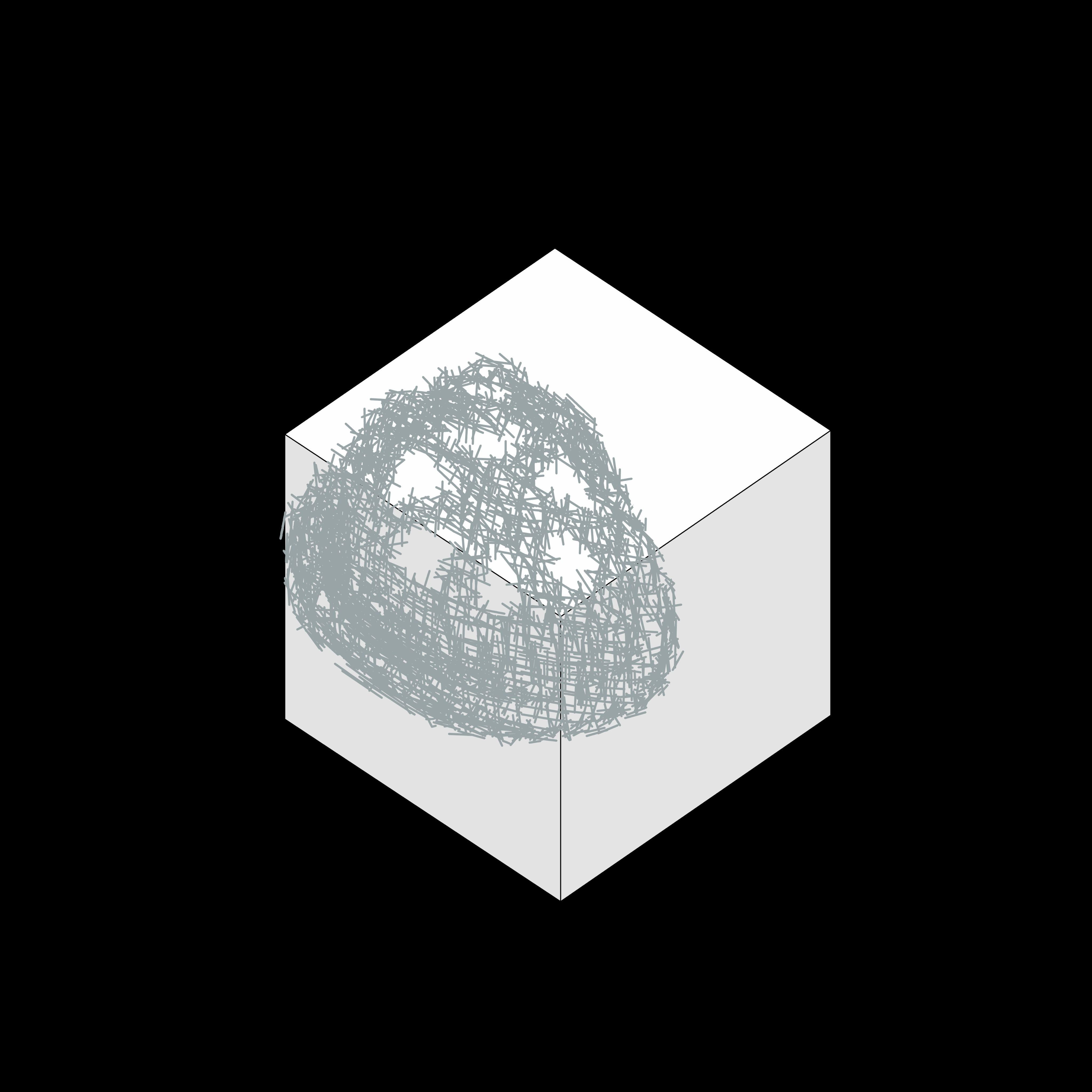
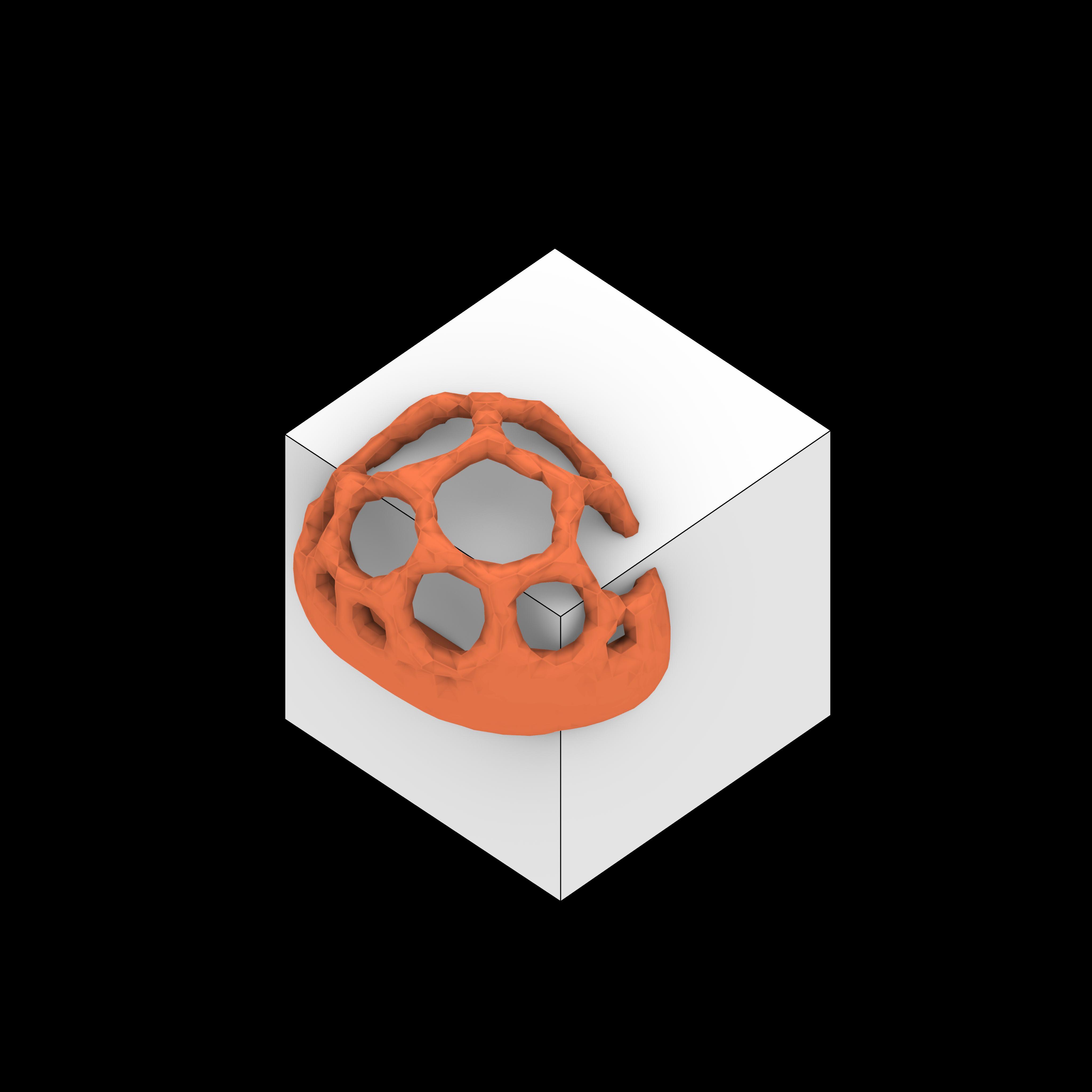
PIPES ASSIGNMENT TIMELINE
initial form-finding stage without database constraints to progressively refined stages incorporating real database matching,
The pipe assignment process evolved from an length-based fitting to eliminate offcuts, and finally, an adaptive structure that optimizes geometry to accommodate pipes efficiently.
Refer to appendix pg. 129 for more content.
NON-ADAPTIVE PIPE
MATCHING
REAL DATABASE
CUT PIPES
NON-ADAPTIVE PIPE COUNT
REAL DATABASE
FITTED PIPES
NON-ADAPTIVE PIPE COUNT
REAL DATABASE
ADAPTIVE PIPE MATCHING
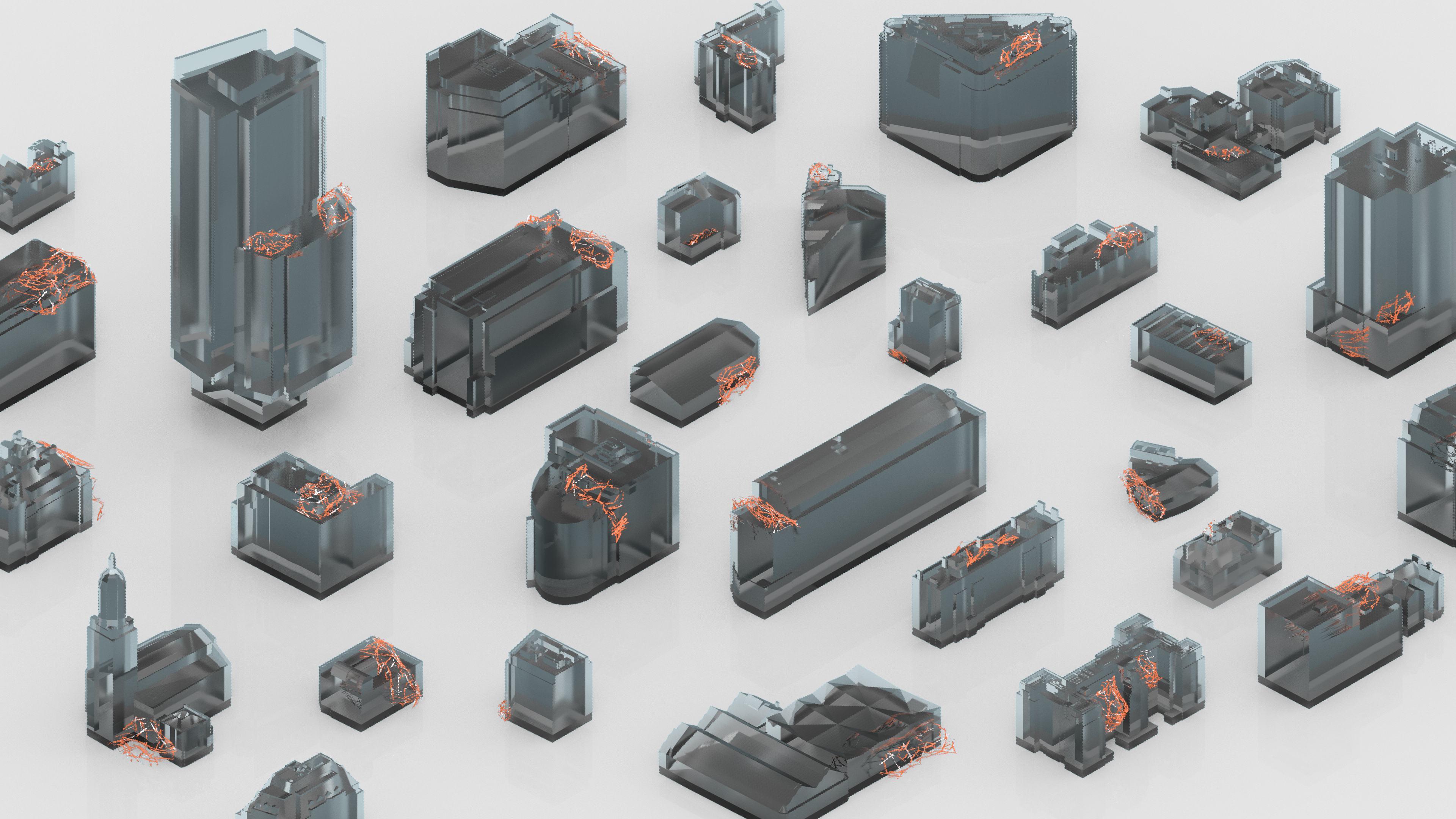
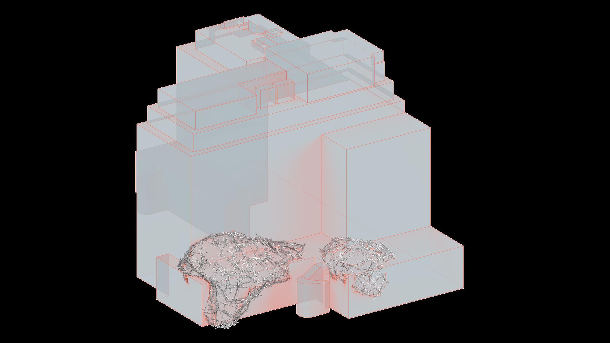
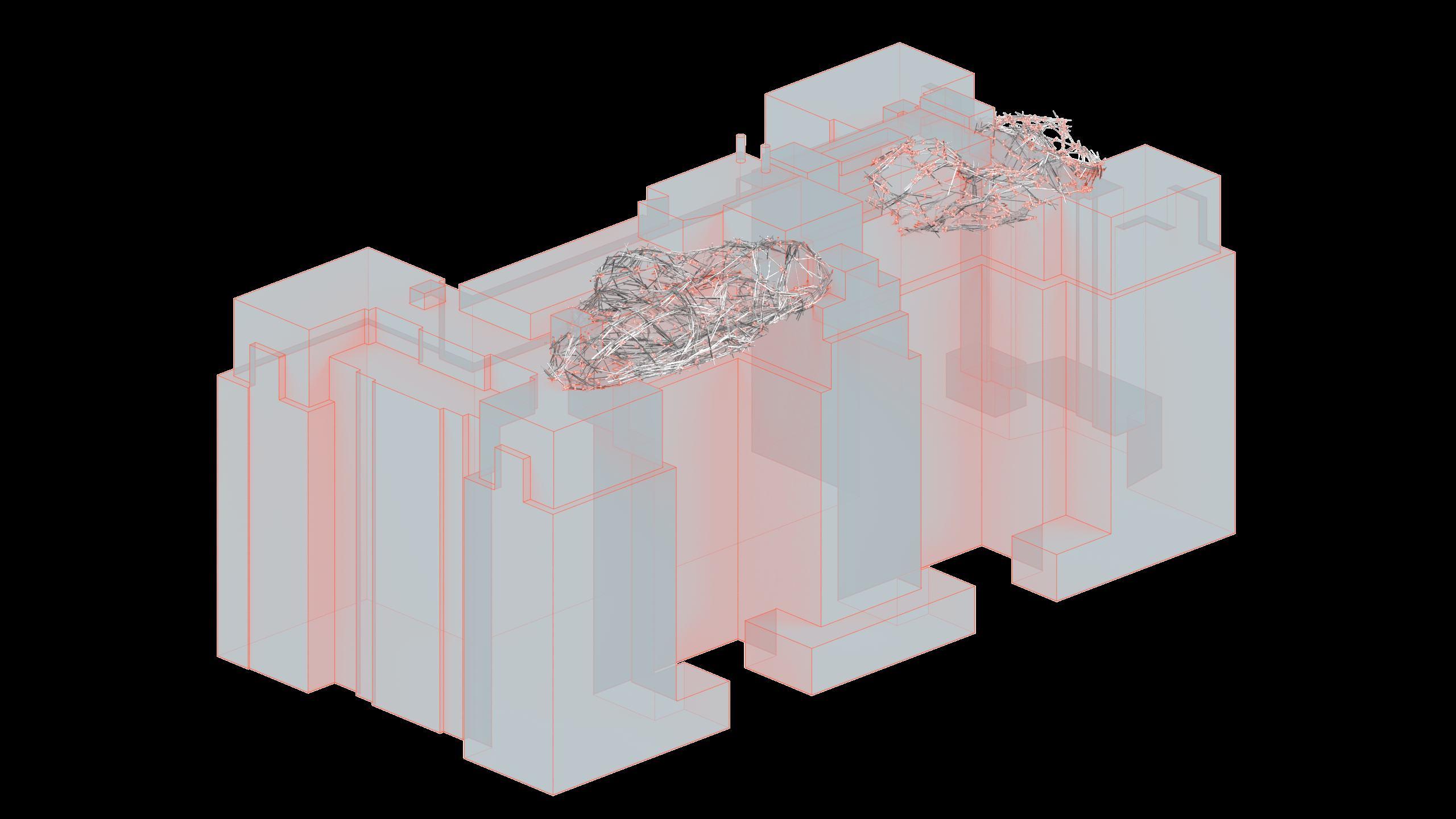
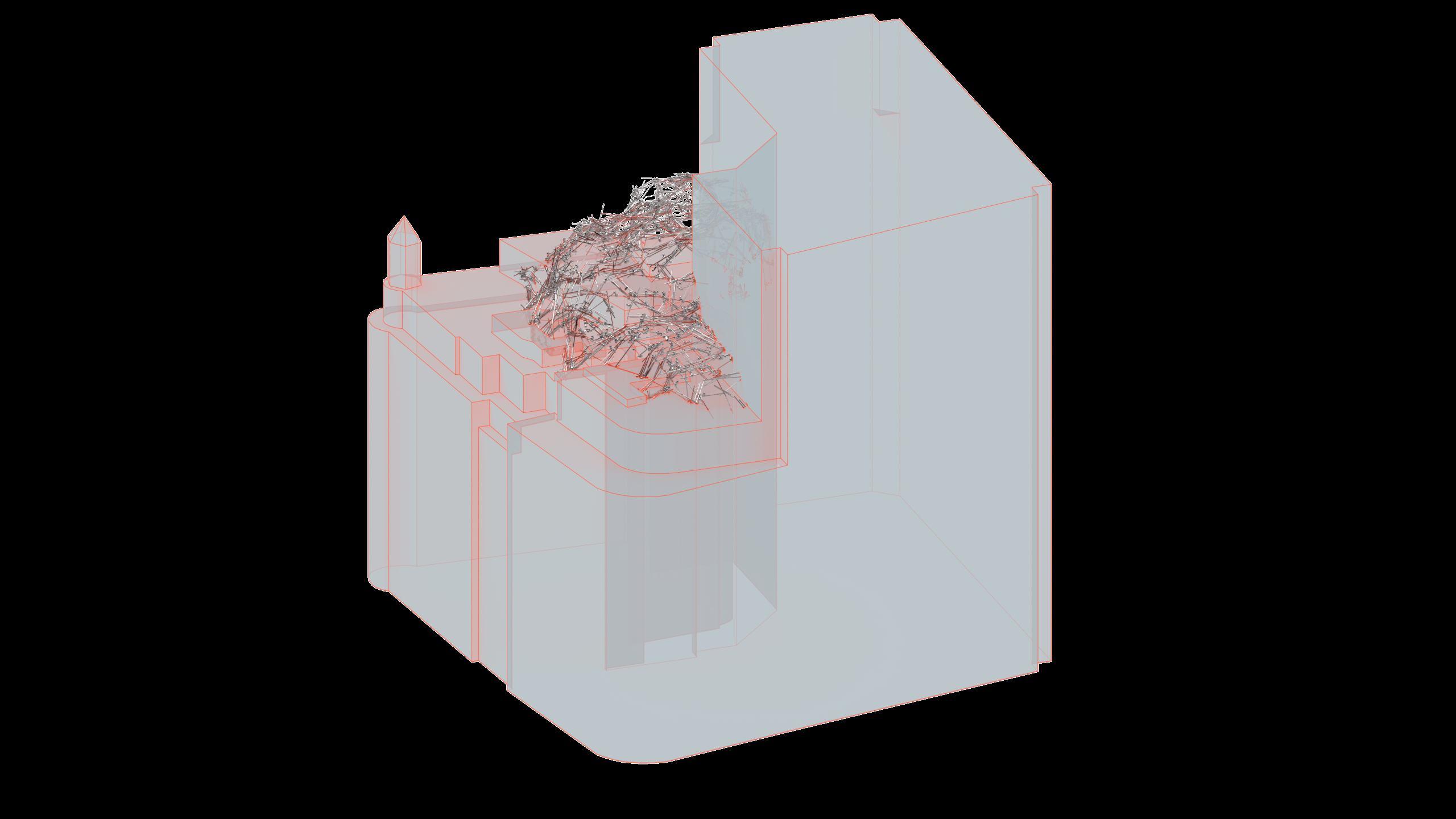
ADAPTABLE ACROSS SCALES
COMPLEX STRUCTES ACROSS SCALES
FOCUS AREAS
PHYSICAL PRODUCT
SKIN CREATION
ASSEMBLY + AR
AREAS
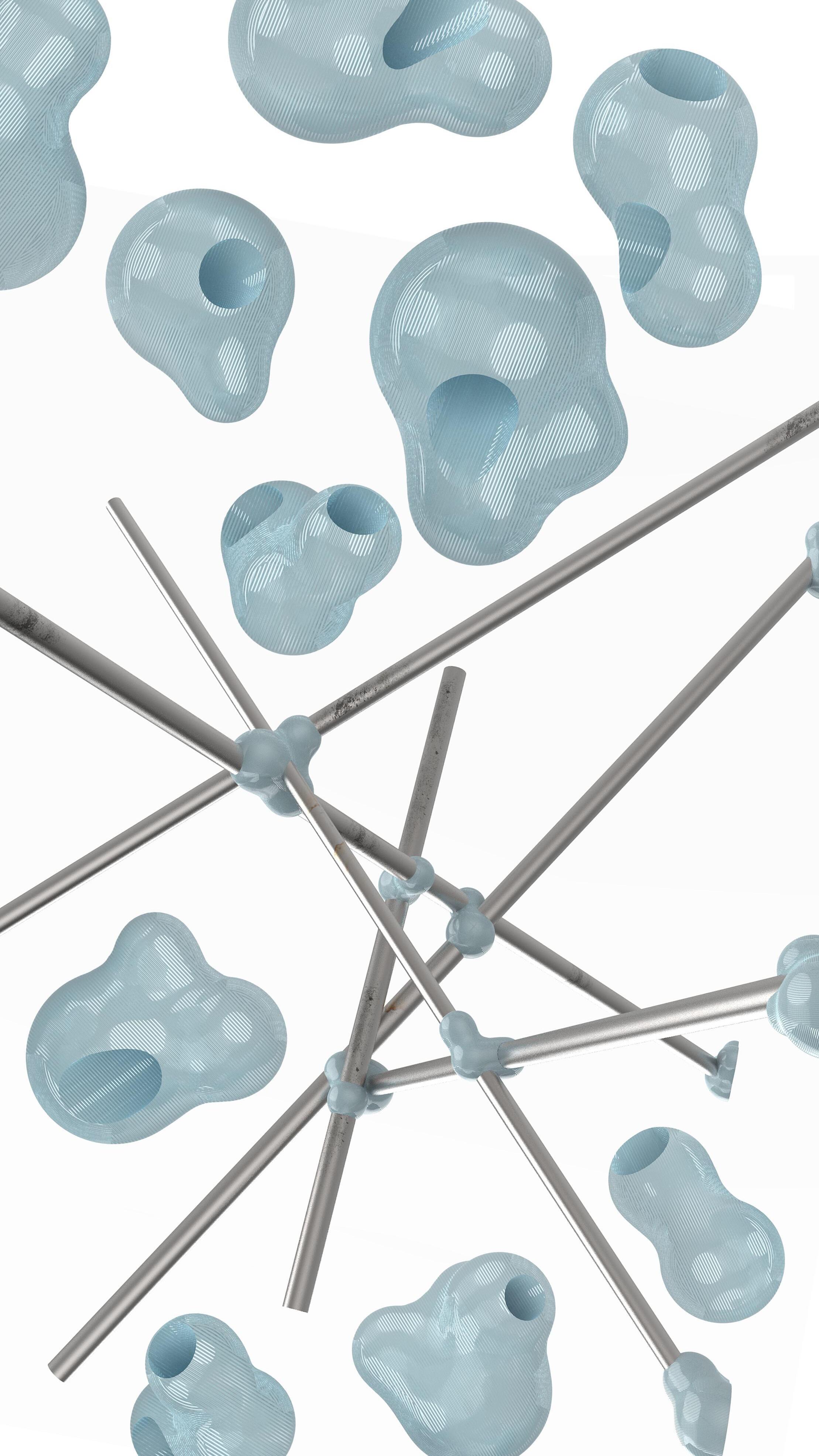
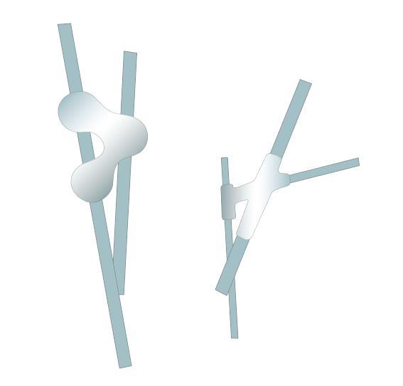
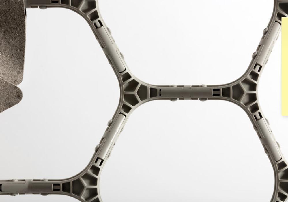
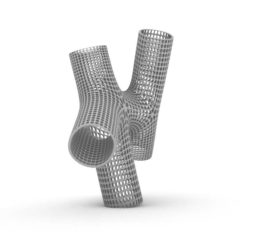
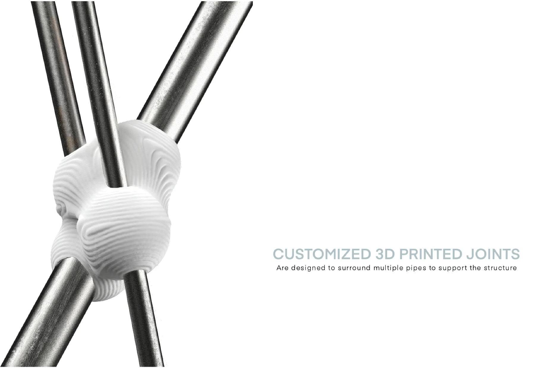
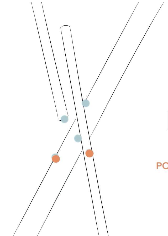
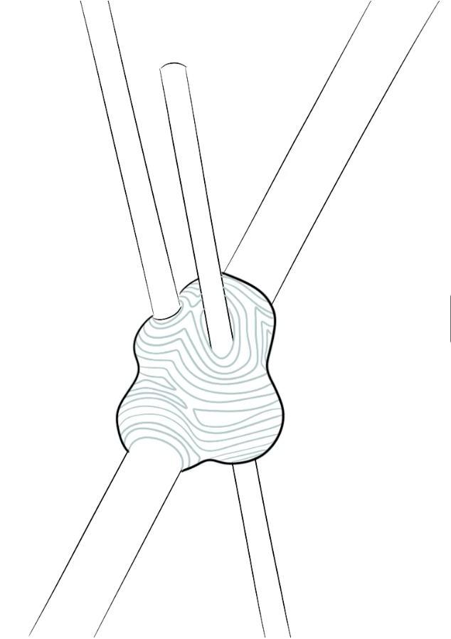
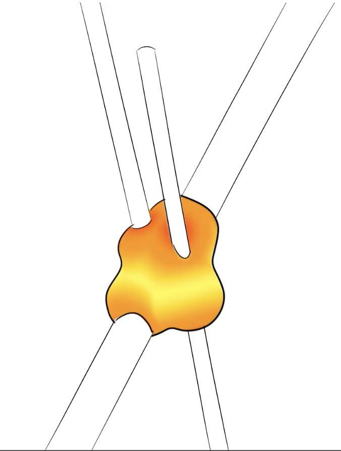
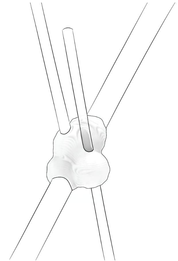
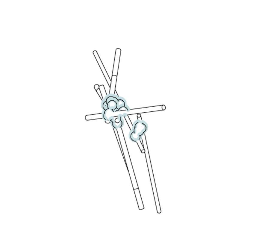
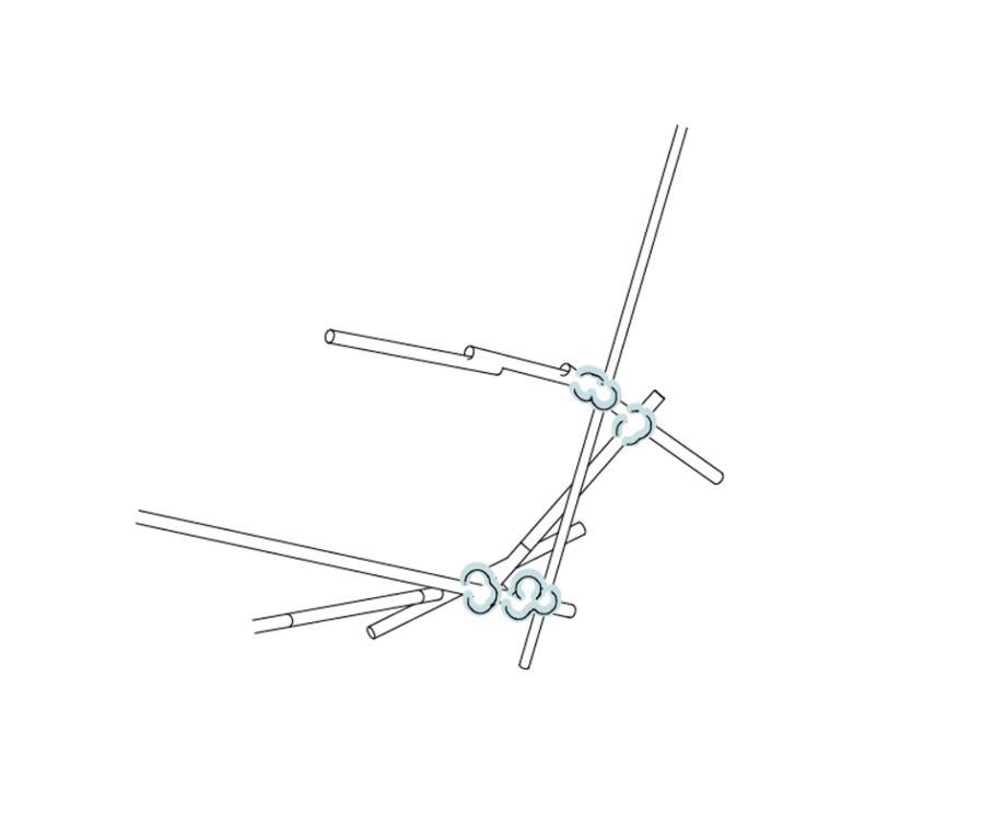
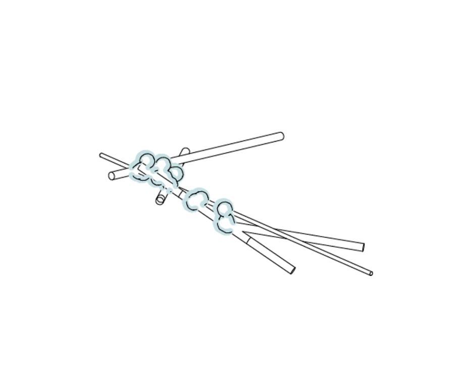
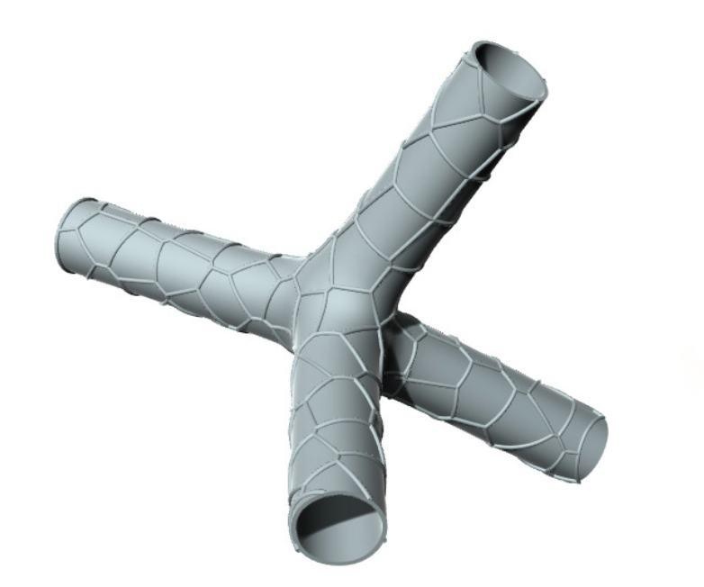
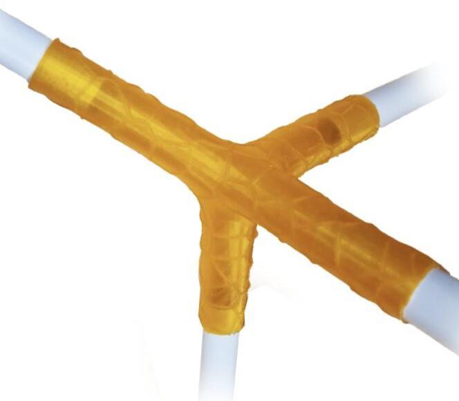
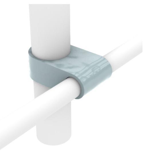
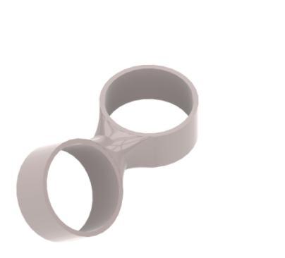
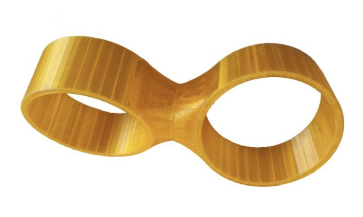
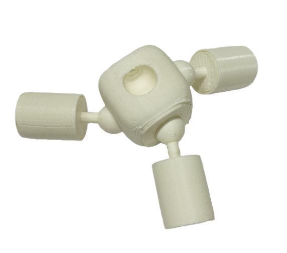
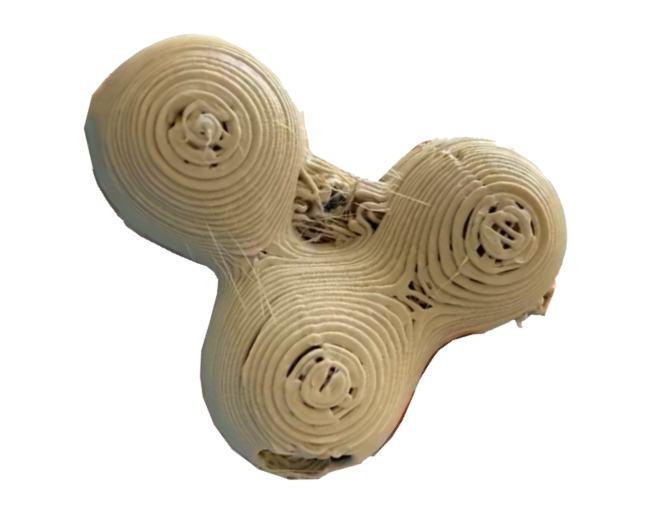
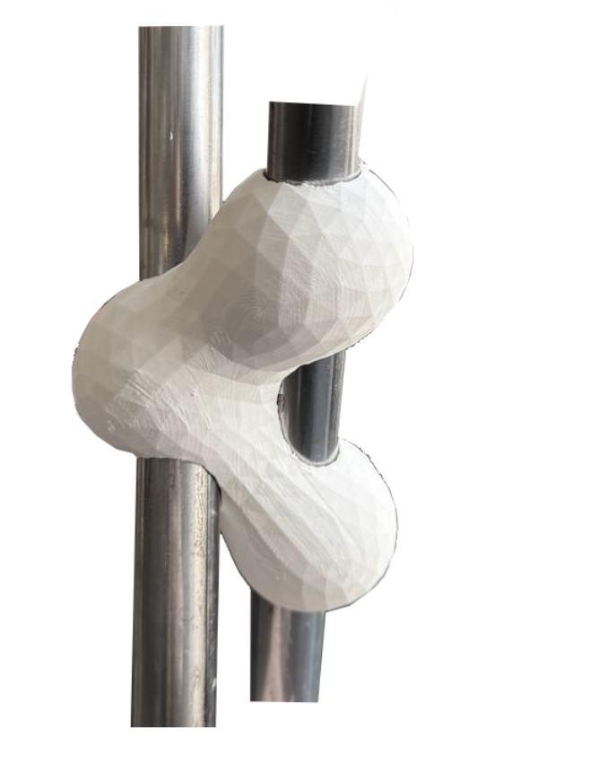
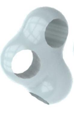
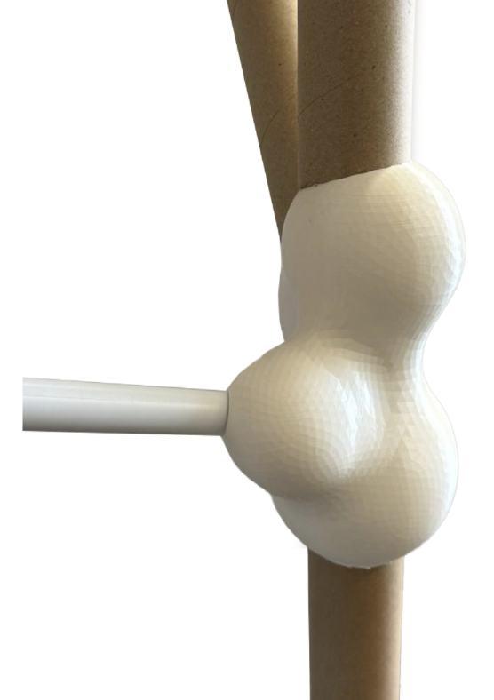
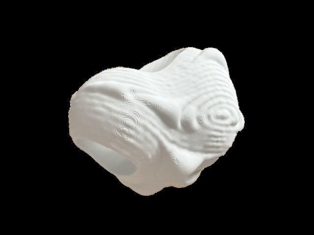
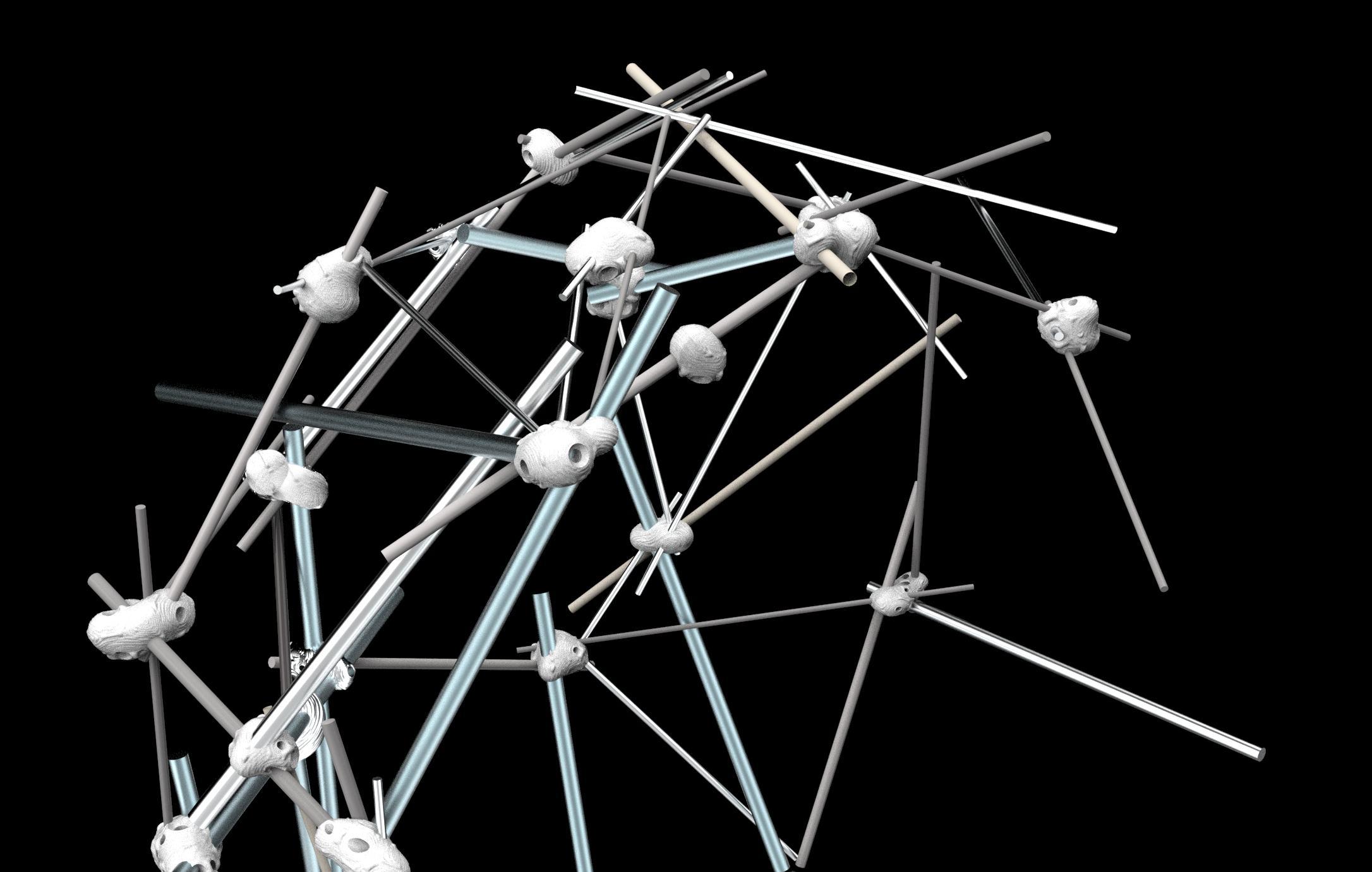
JOINT DESIGN
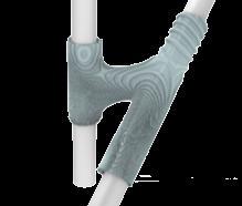
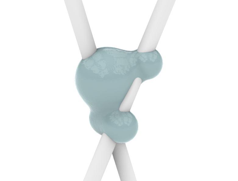
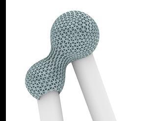
ADAPTABLE JOINT TYPE
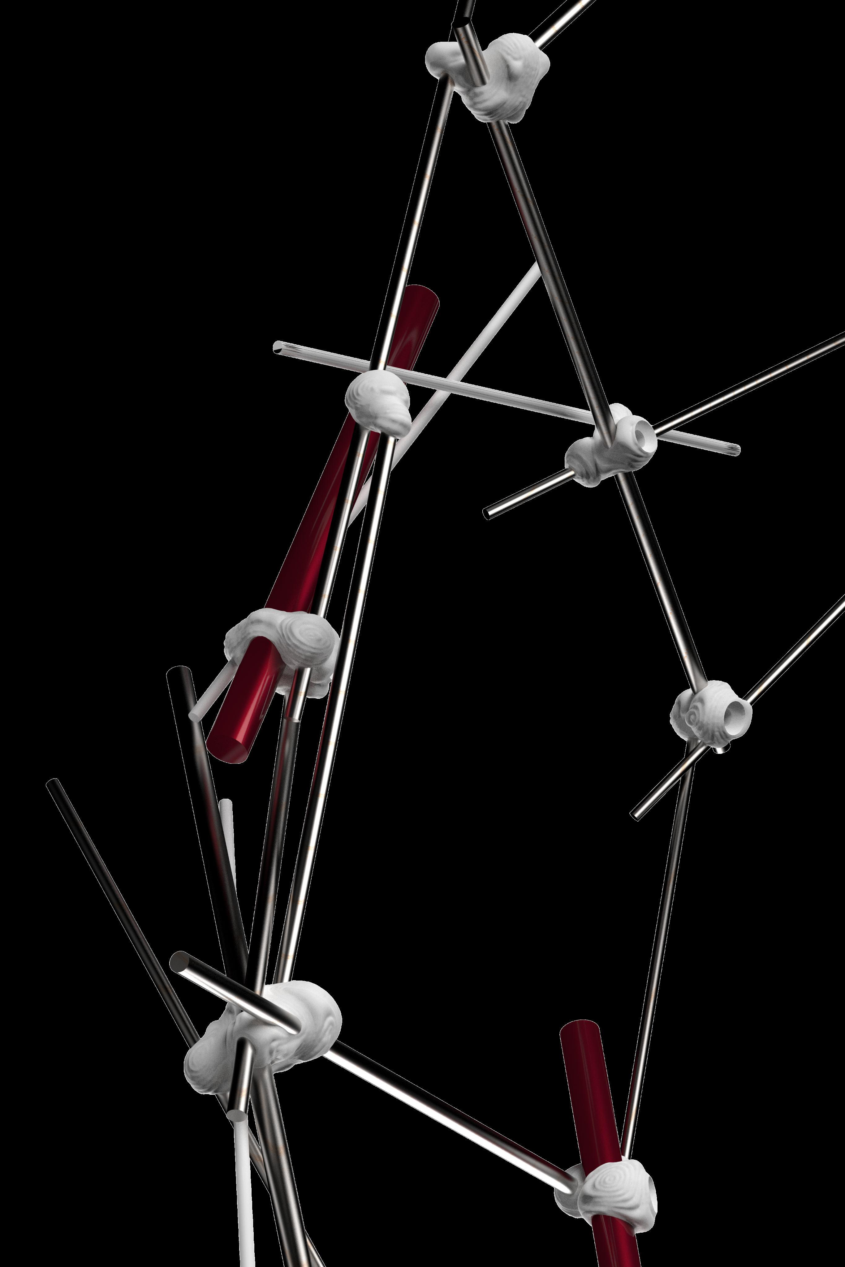
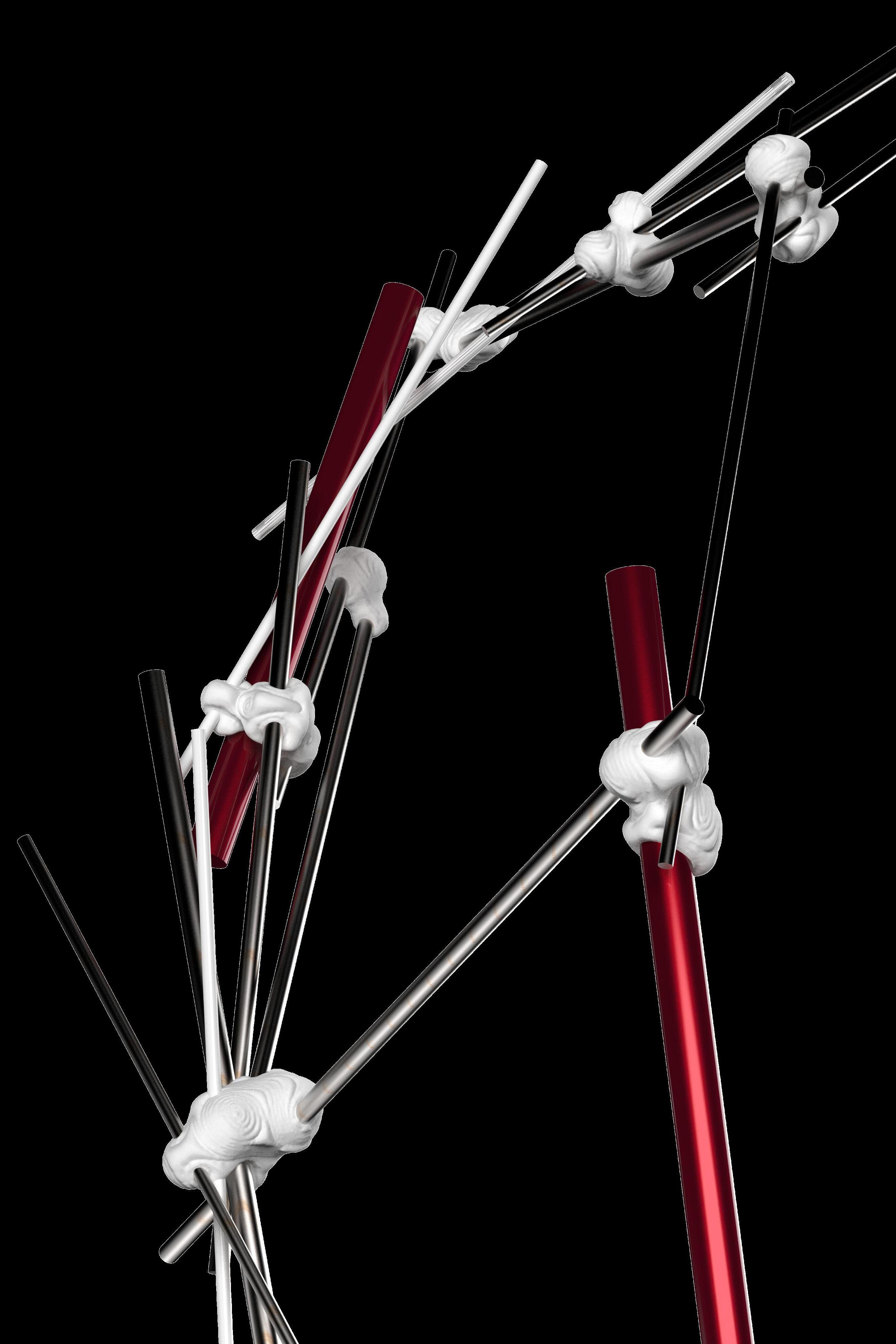
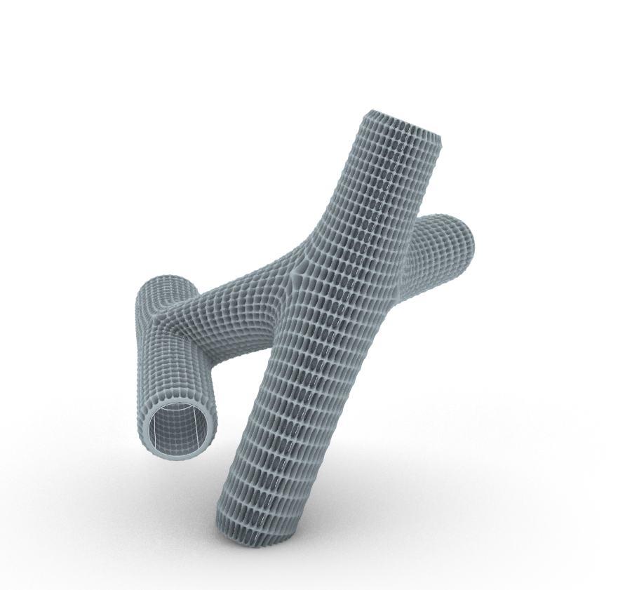
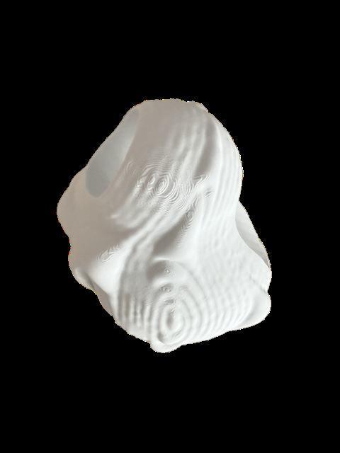
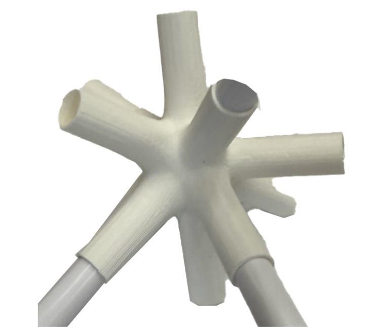
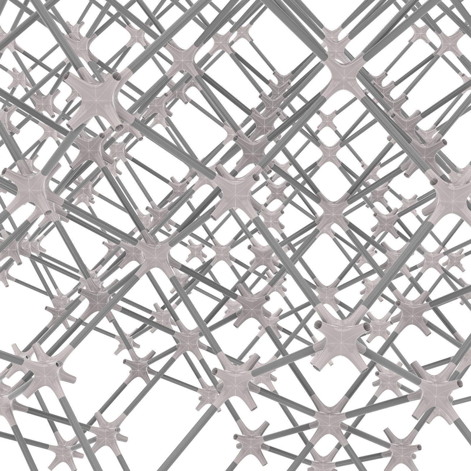
3D-printed, blob-like forms allowing structures to evolve organically without compromising design. They are especially effective in where dimensional inconsistencies are common. adapt to regular and irregular geometries. accommodating reclaimed materials, as well as additional uses,
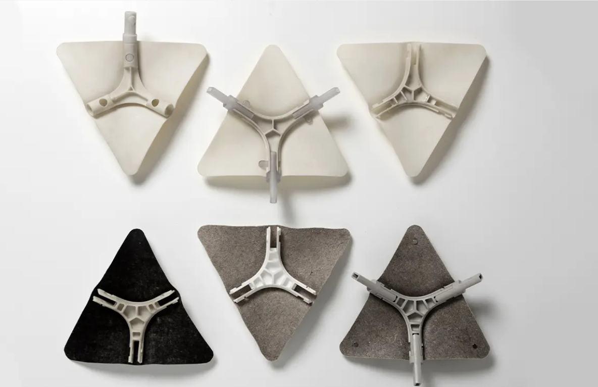
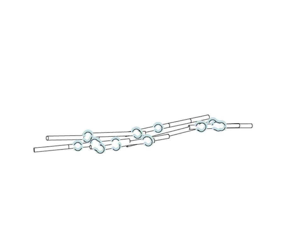
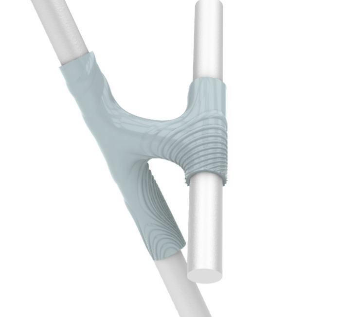
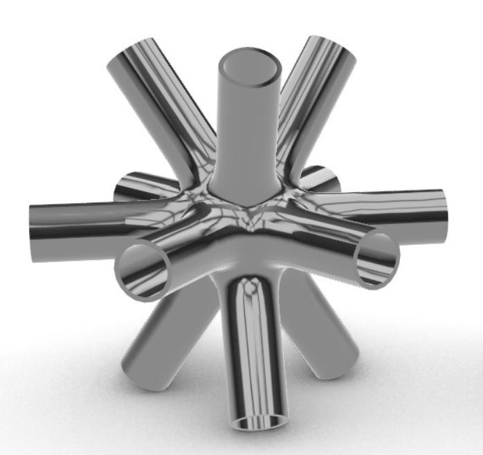
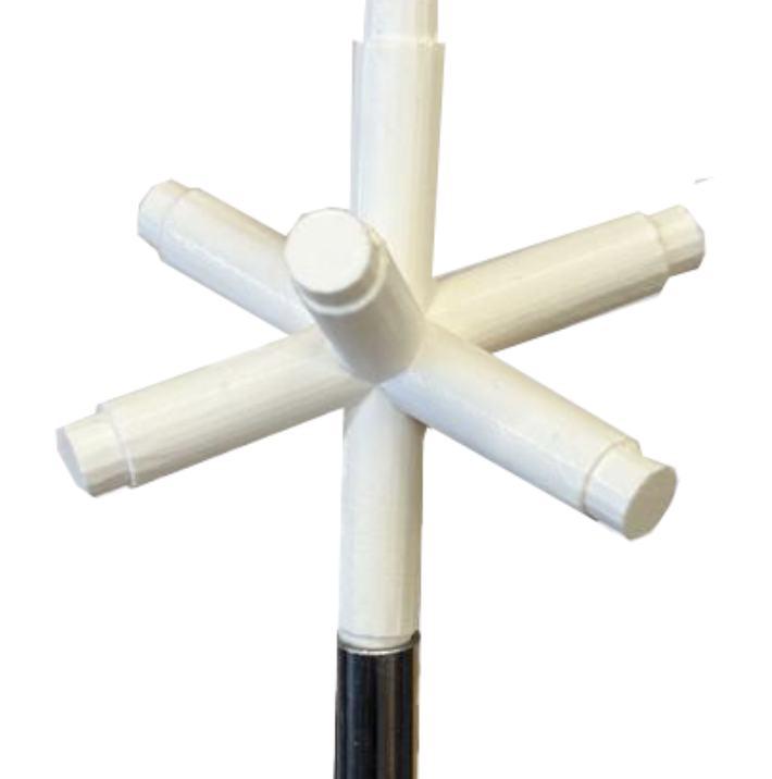
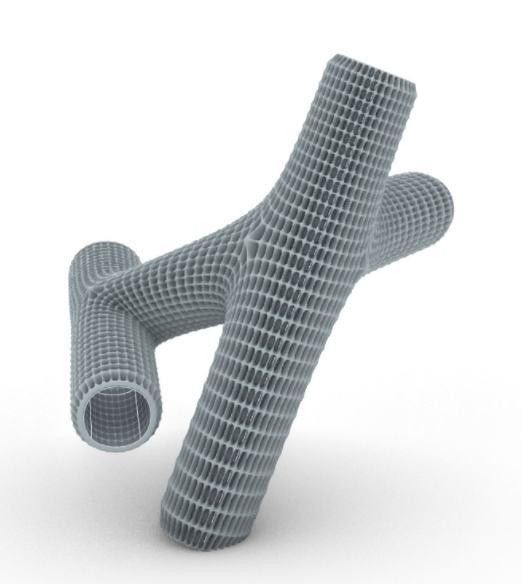
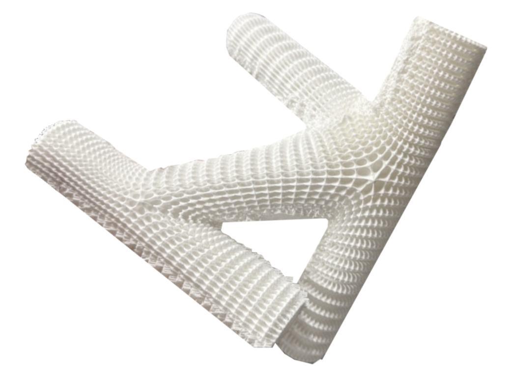
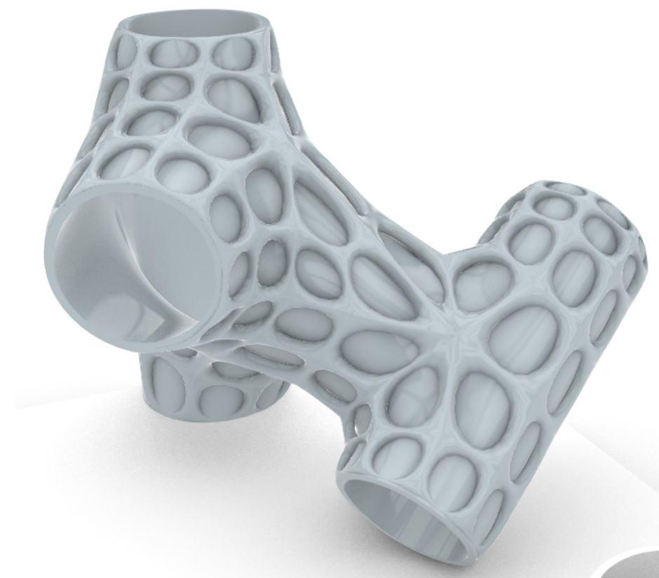
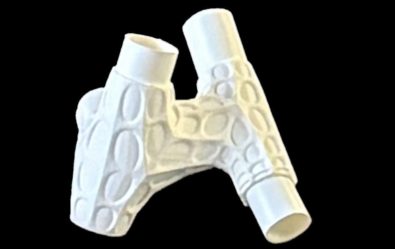
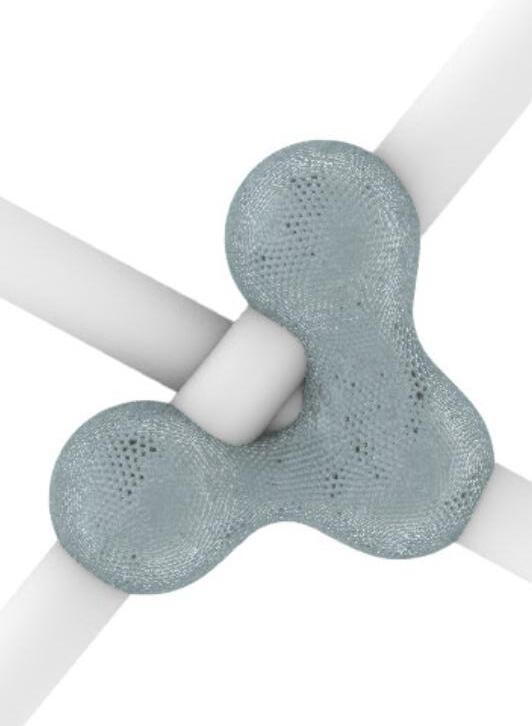
JOINT DESIGN EVOLUTION
The evolution of joint design from standardized to fully customized solutions, demonstrating a progression in adaptability, performance, and fabrication techniques.
Early iterations explore generic connector geometries suitable for mass production, while later designs leverage advanced computational modelling and additive manufacturing to create highly optimized, site-specific joints.
These customized joints respond to unique structural conditions, pipe orientations, and load requirements, achieving seamless integration with the overall framework while reducing material waste and enhancing structural efficiency.
Refer to appendix pg. 113-114 for more content. CUSTOMIZED
Refer to appendix pg. 141 for more content.
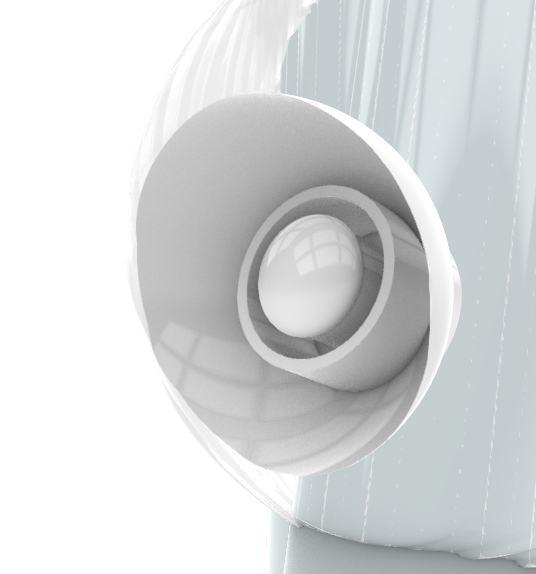
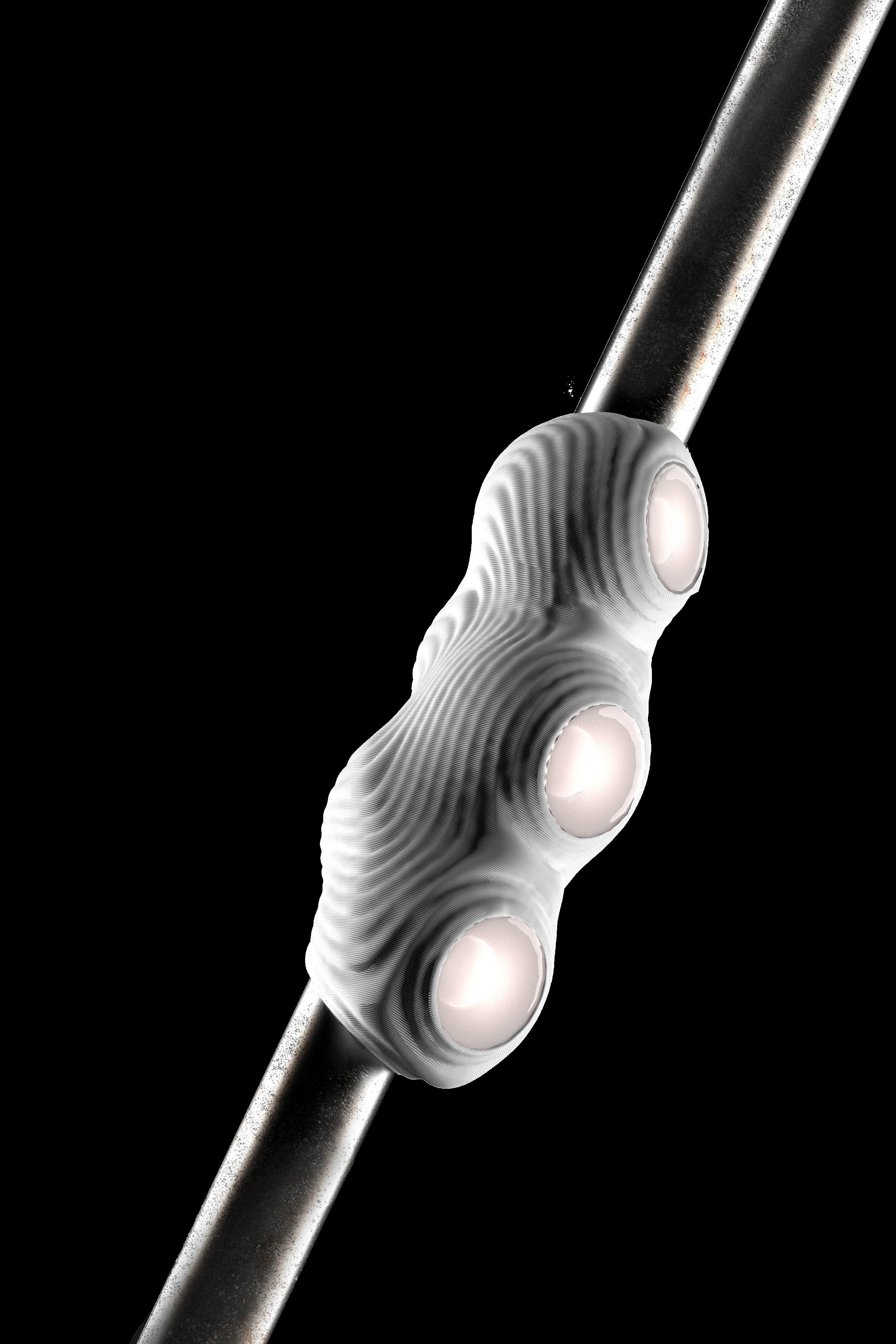
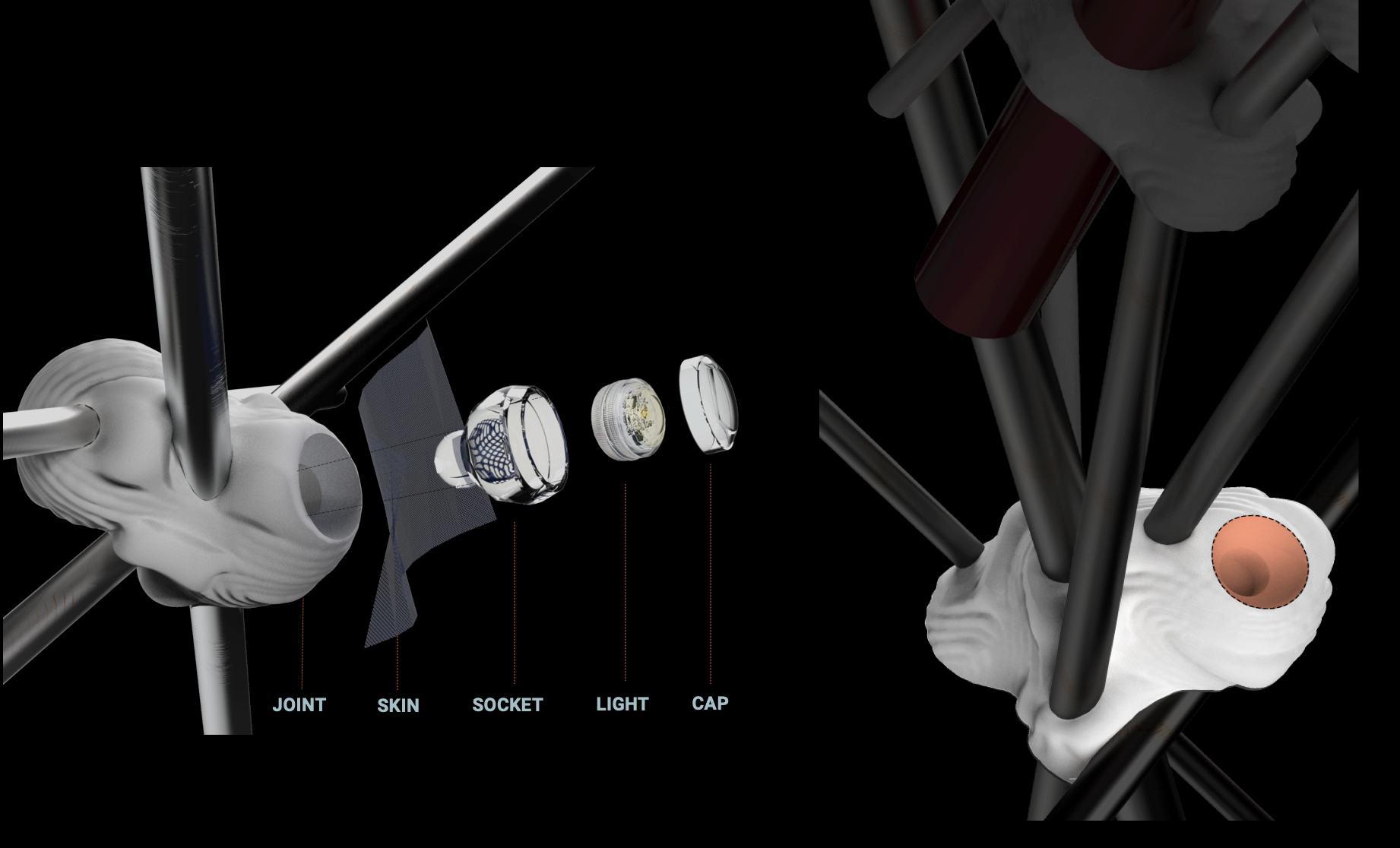
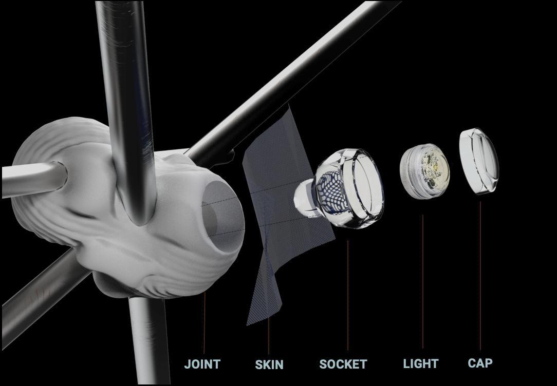
ADDITIONAL FEATURES
LIGHT FIXTURE:
Joints can be fixed with lighting based on
FURNITURE
LESS VIABLE MATERIAL
The pipe furniture was developed
By integrating these robust components, the approach reduces reliance on smaller, less structurally viable materials, enhancing durability while streamlining construction. both to accommodate various programmatic needs and to explore the use of larger pipe elements within the design. This strategy balances functional adaptability of spaces with efficient material use.
Refer to appendix pg. 115-116 for more content.
SMALLER DIAMETER PIPE FURNITURE
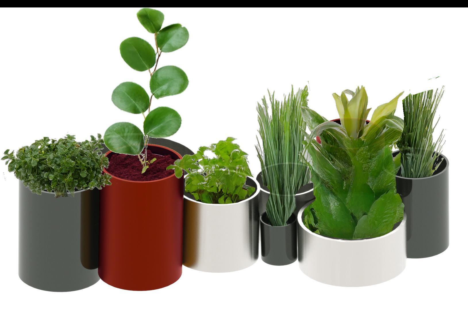
PLANTERS
BENCHES
PICNIC TABLES
CHAISE LOUNGES
FURNITURE PLUG - INS
TABLE AND CHAIRS
DINING TABLES
PLANTERS
FURNITURE PLUG - INS
LARGER DIAMETER PIPE FURNITURE
Furniture can be created using It can also incorporate larger sheet material to create table tops and other furniture parts. less viable pipe material.
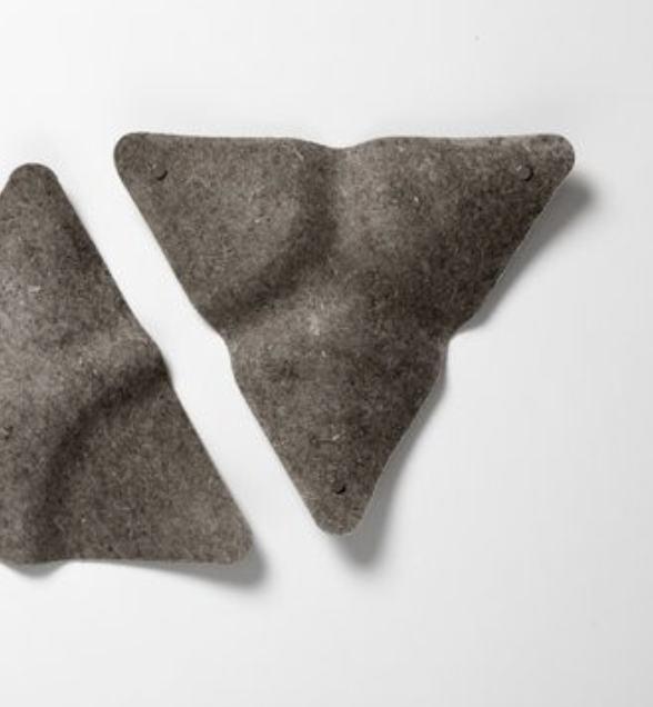
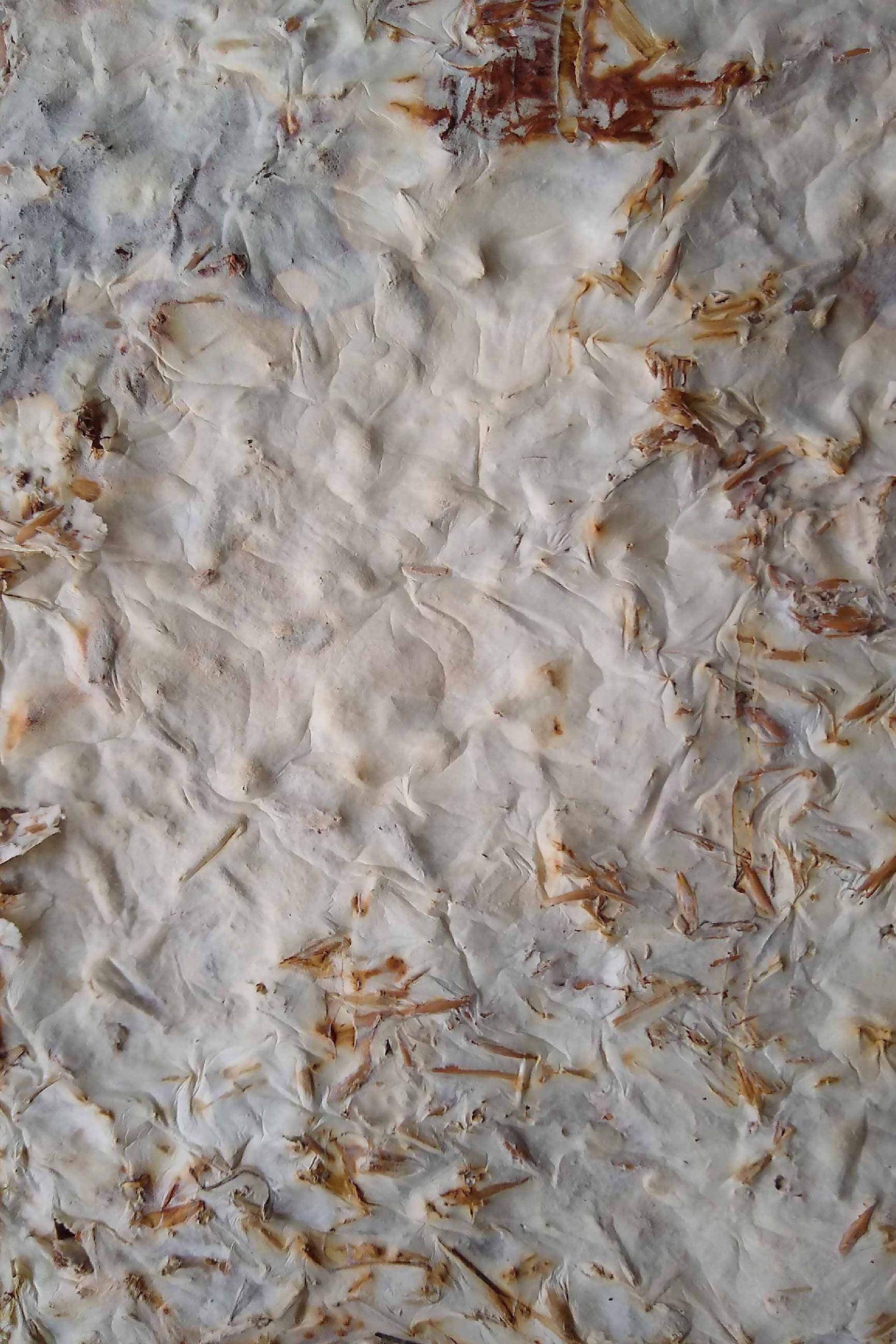
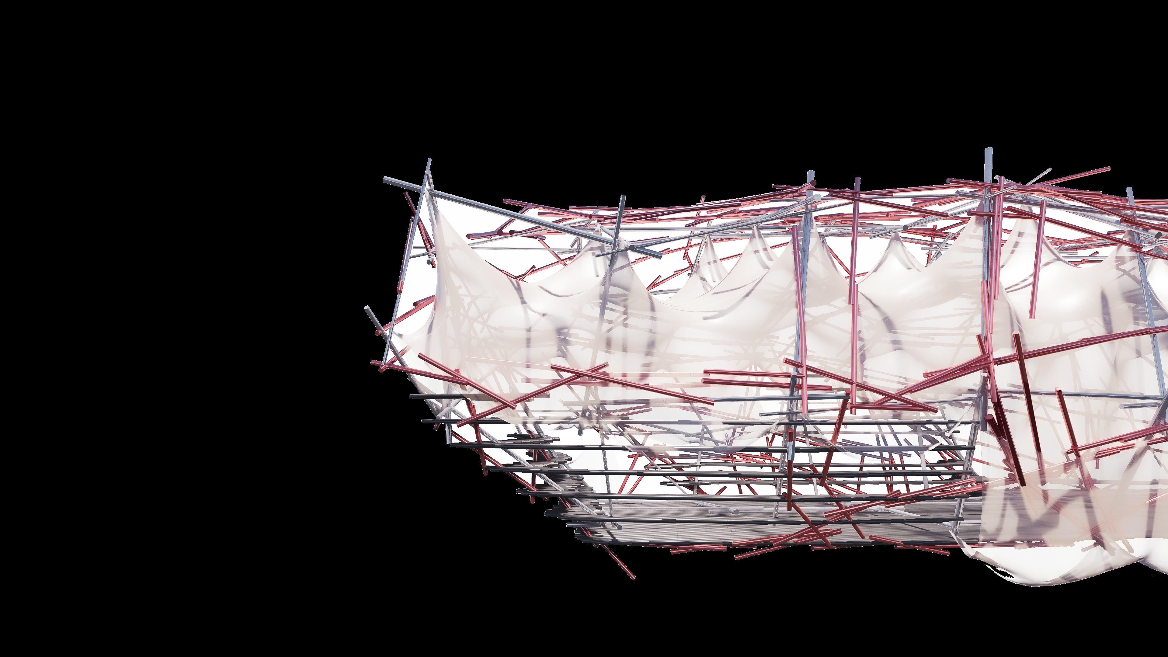
SKIN DESIGN
ADAPTABLE SKIN DESIGN
This adaptable façade system, constructed from , offers a flexible form that and programmatic needs while emphasizing the low-cost, sustainable reuse of materials. The translucent surface both , creating a responsive and expressive architectural layering. recycled parachute fabricadapts to structural changes provides enclosure and filters light
Refer to appendix pg. 117-119 for more content.
PARACHUTE MATERIAL REUSE
· High tensile strength.
· High weather and water resistance.
· Lightweight and high strength.
· Recycling and sustainability.
· Translucent.
· Colour and aesthetic expression
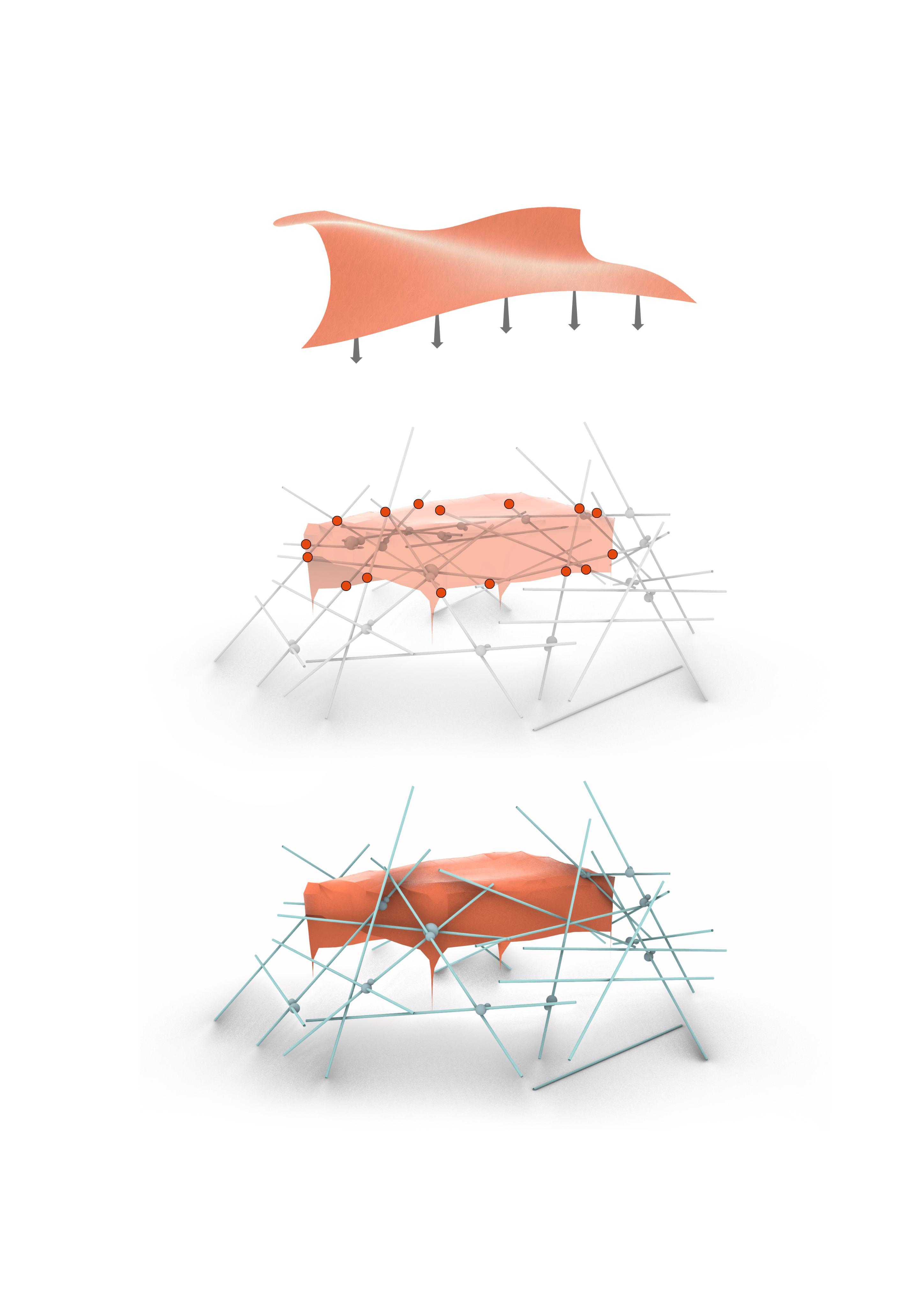
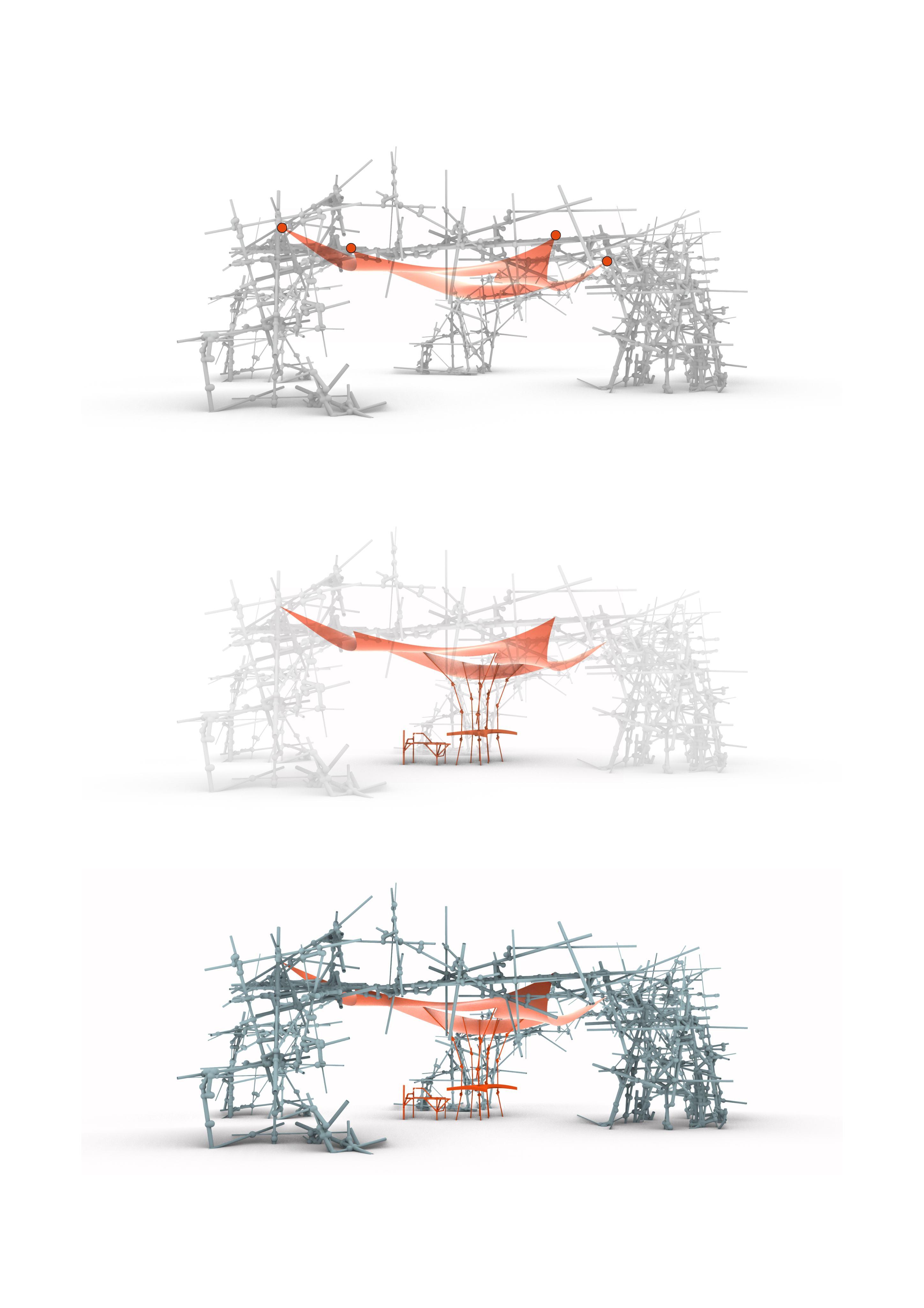
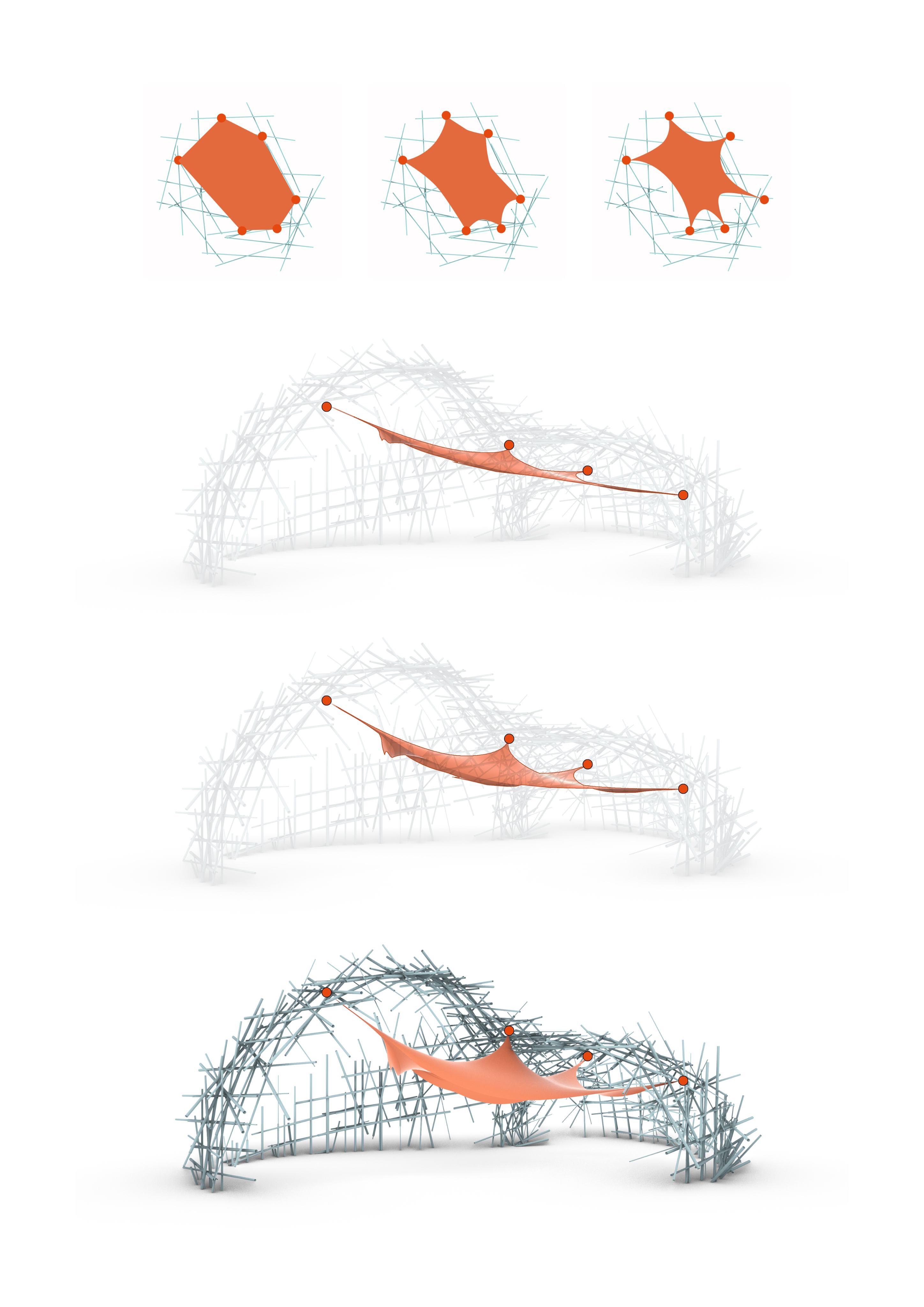
SKIN DESIGN EVOLUTION
The design of structural skin is a The design explores the tension relationship between development from the initial covering form to morphological control. the fabric and the frame through the arrangement of different support points.
Extension into furniture structures
Overall structure
Adjust the shape
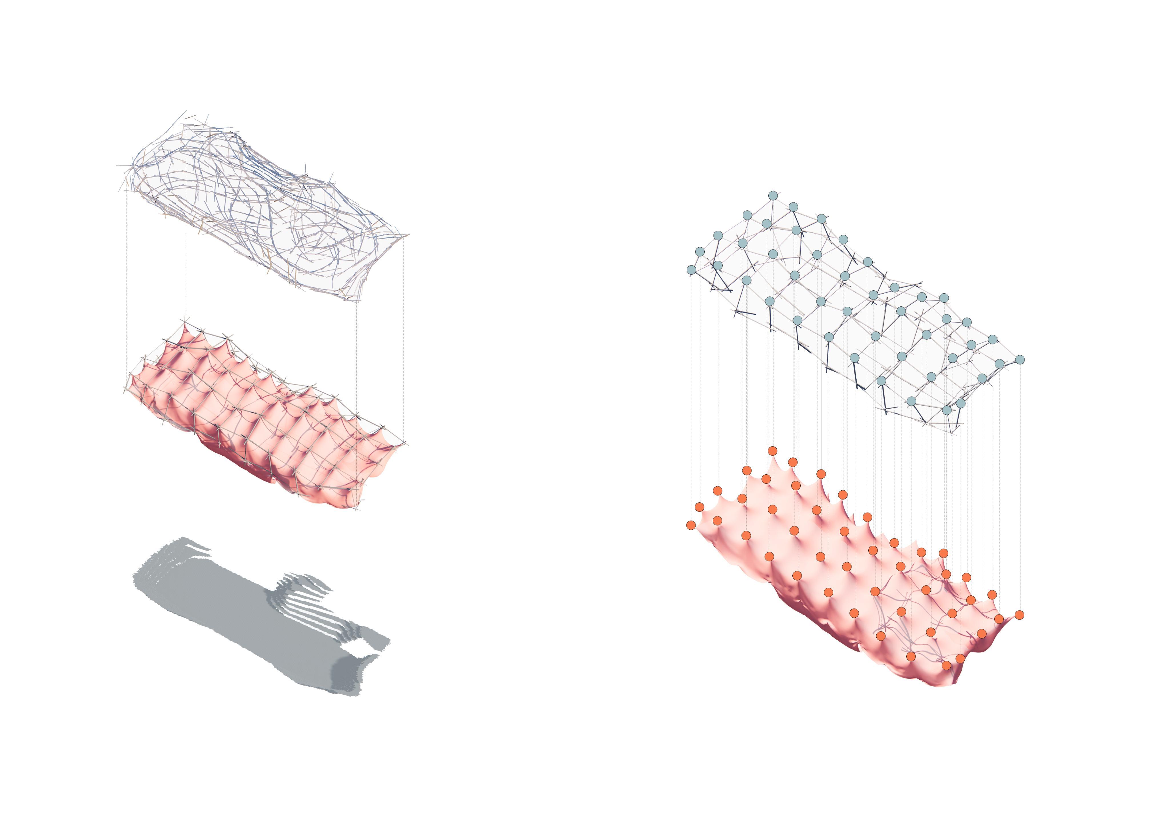
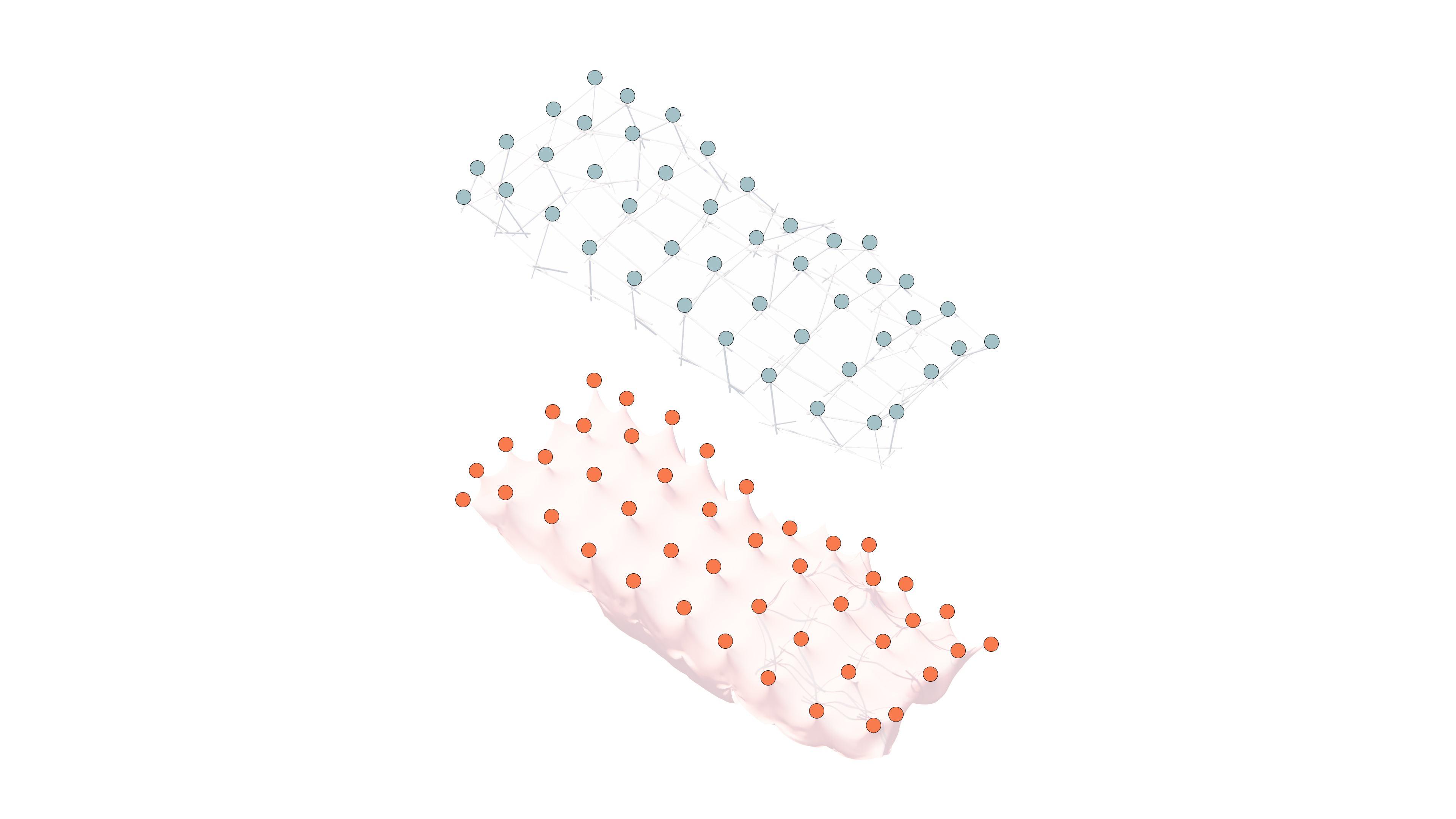
SKIN METHOD OF ATTACHMENT
In terms of details, by constructing , efficient hanging and morphological response between the skin and the spatial scaffold are achieved, a hanging point structure layer ensuring structural stability and flexibility in geometric control.
SKIN VARIETY
Based on the skin system can flexibly achieve a variety of states, enhancing its responsiveness and structural expression in different scenarios. user preferences, environmental requirements, and spatial functions, from completely open to partially covered to fully enclosed,
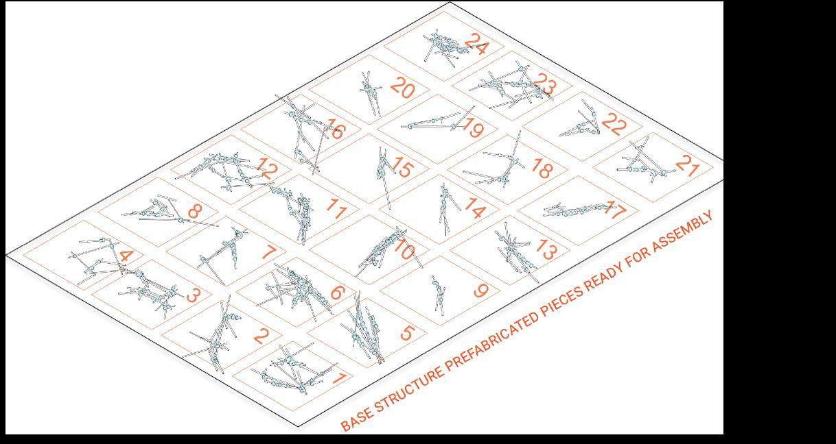
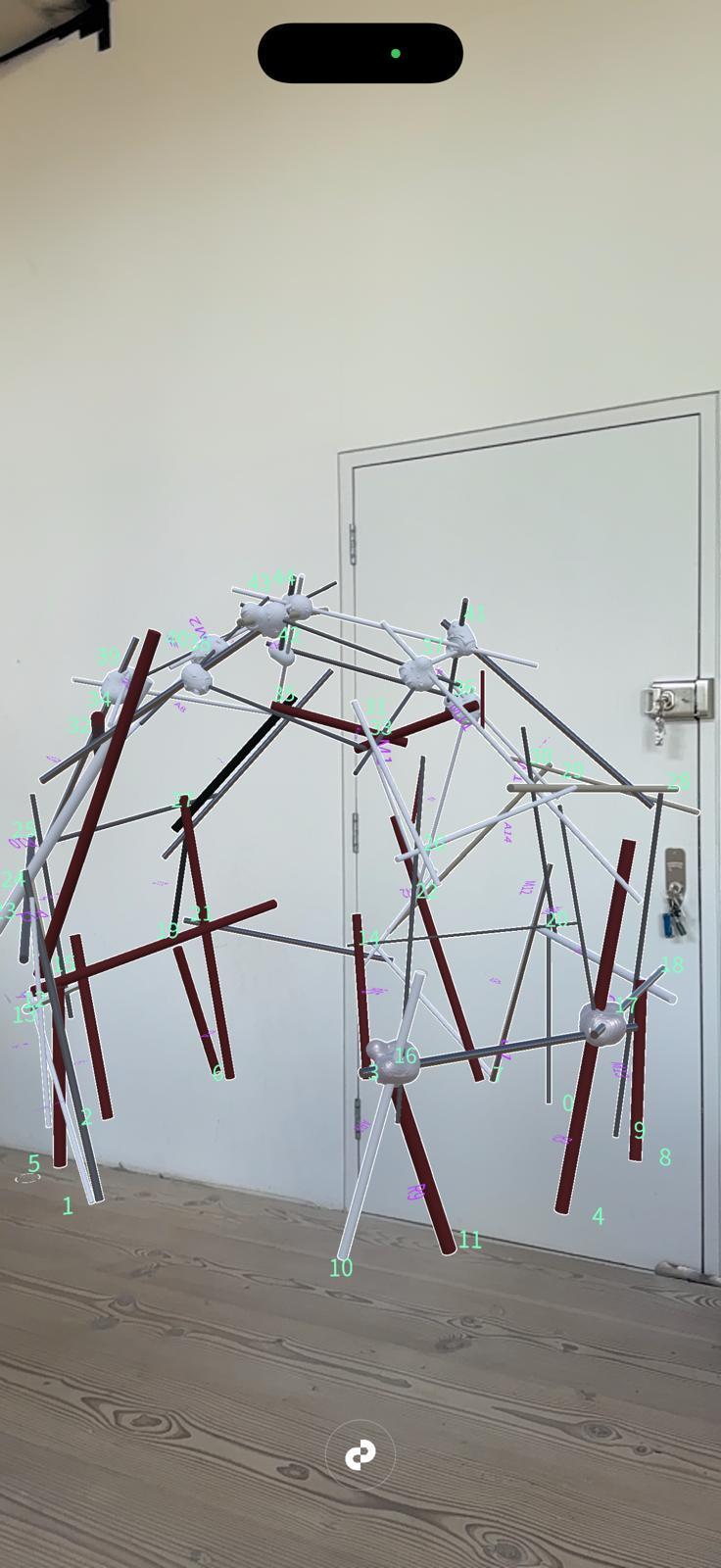
PREFABRICATED ASSEMBLY
STEP-BY-STEP ASSEMBLY
A series of prefabricated chunks of structure are combined with Using AR the process can be assisted and tracked. on site mapping of stress lines to increase the structures stability.
Refer to appendix pg. 140 for more content.
AR ASSEMBLY ASSISTANCE
STEP-BY-STEP ASSEMBLY
A series of prefabricated chunks of structure are combined with Using AR the process can be assisted and tracked. on site mapping of stress lines to increase the structures stability.
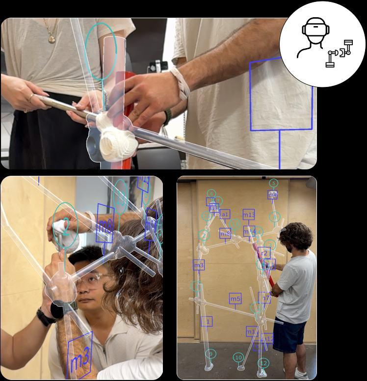
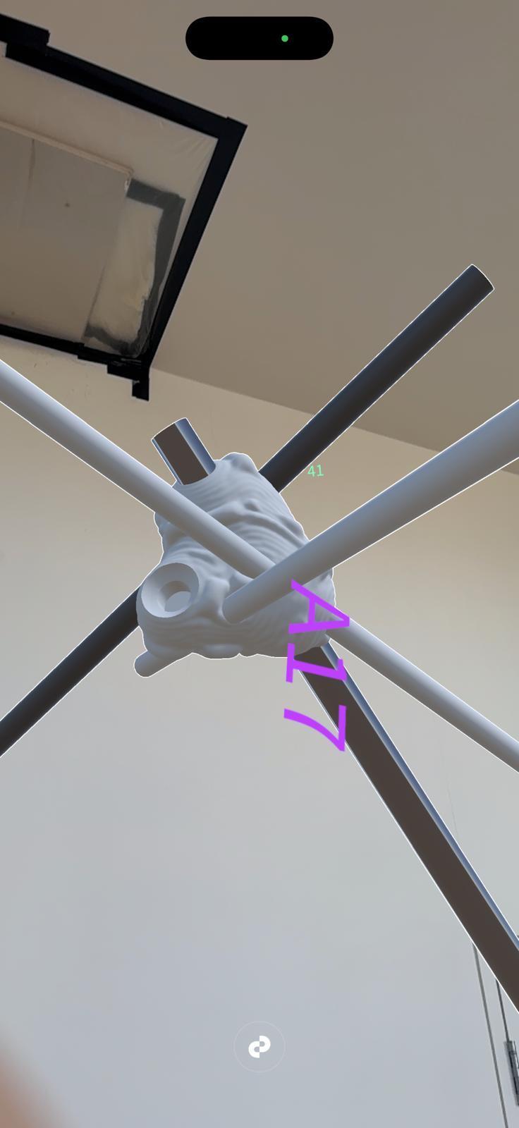
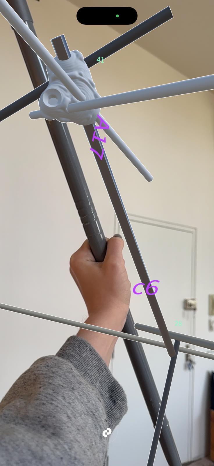
FOLOGRAM ASSISTANCE
When assembling the physical model we used assistance from augmented reality. Using AR the process can be assisted and tracked. Labeling of every piece physically and in the model allowed us to have a more streamlined assembly process.
Fologram allows us to place the 3d model in any space. Projecting it to help us build.
AR ASSEMBLY ASSISTANCE
AR GUIDES
Detailed labeling of joint locations and pipe types helps keep the assembly process in check.
Fologram allows each joint to be shown in AR while we collect and assemble to pipe types and unique joints.
SPECULATIVE STUDIES SPECULATIONS
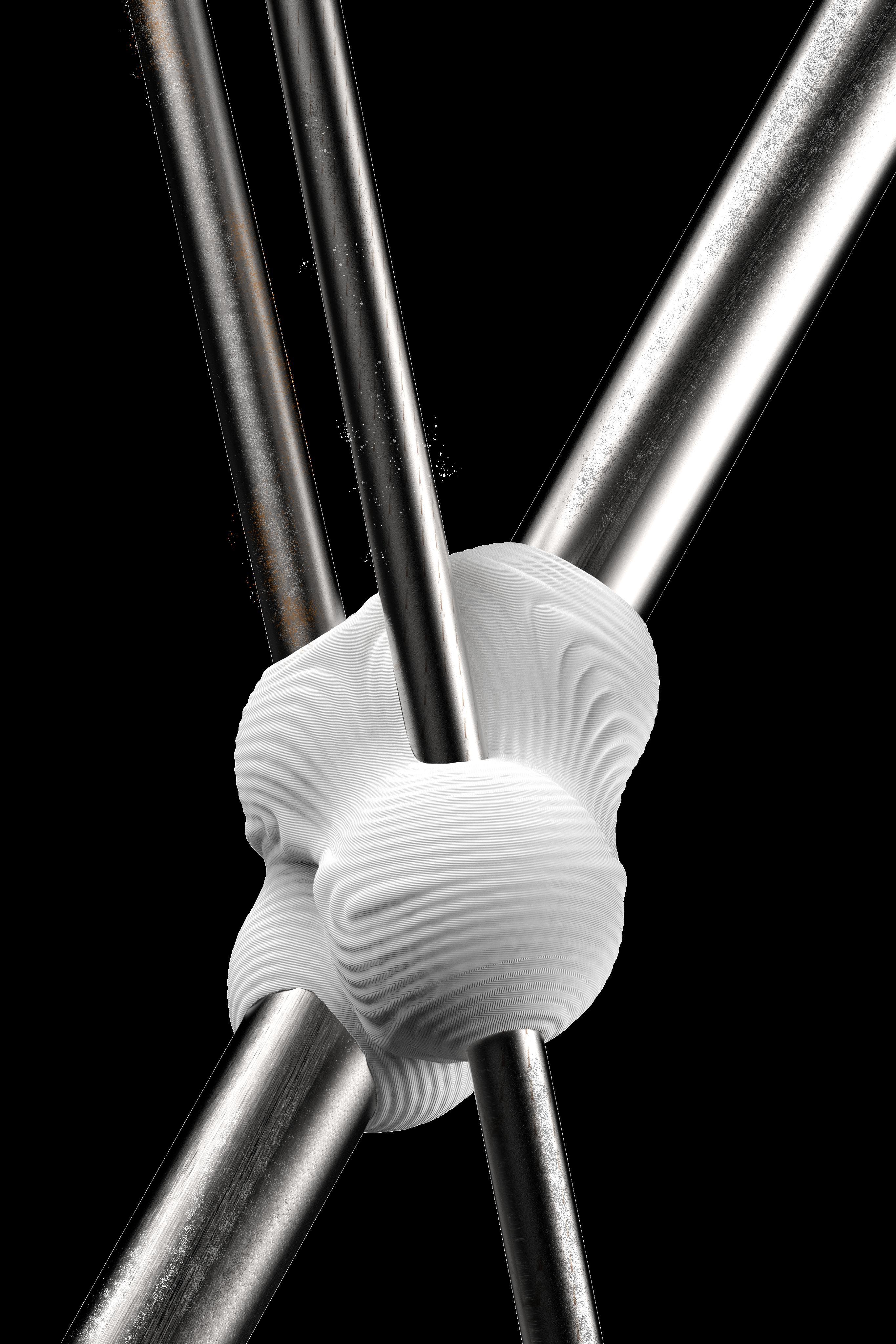
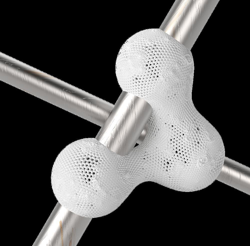
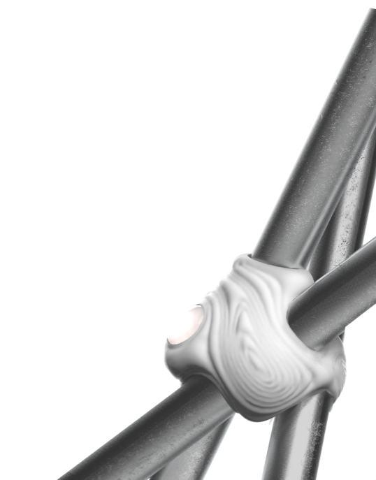
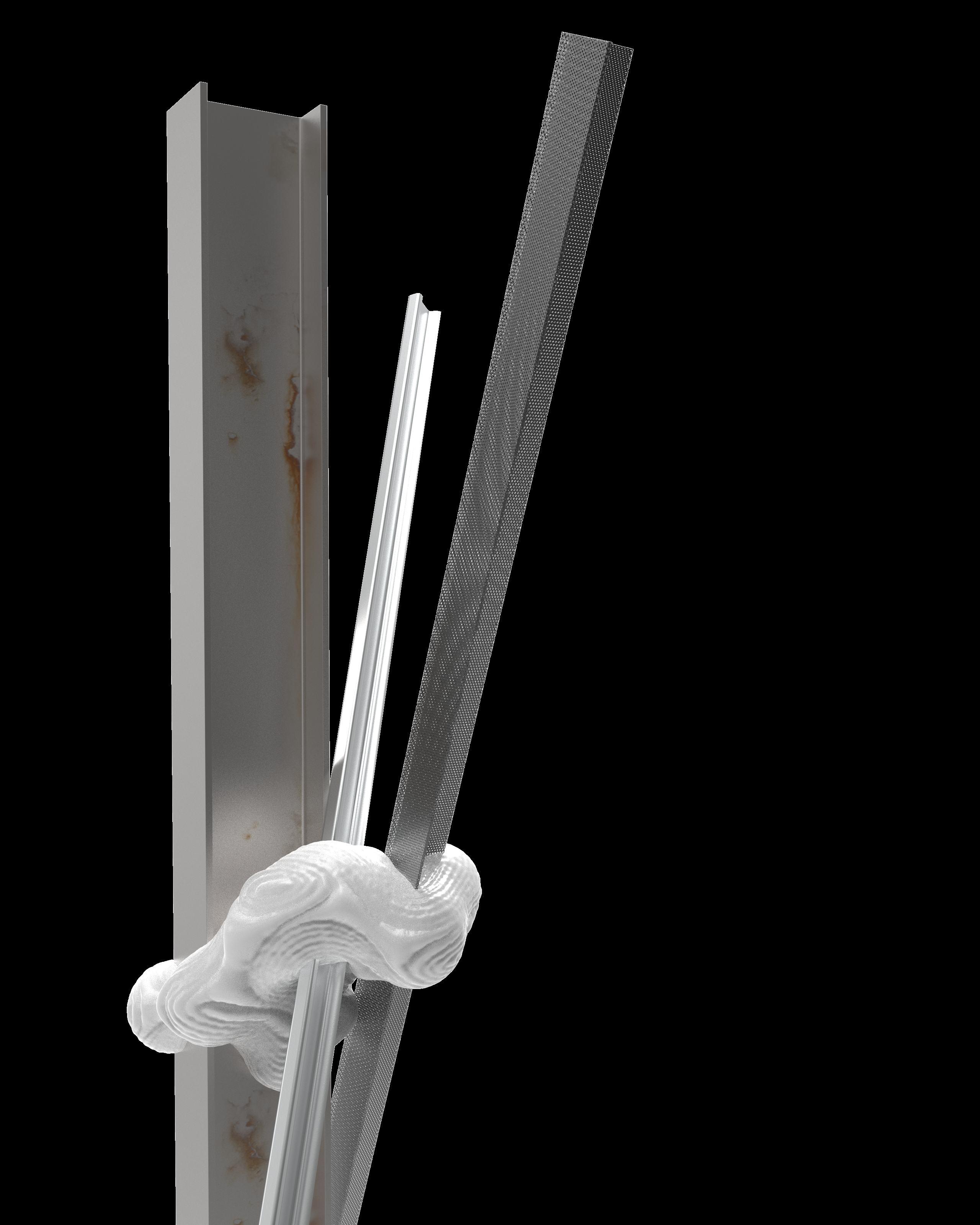
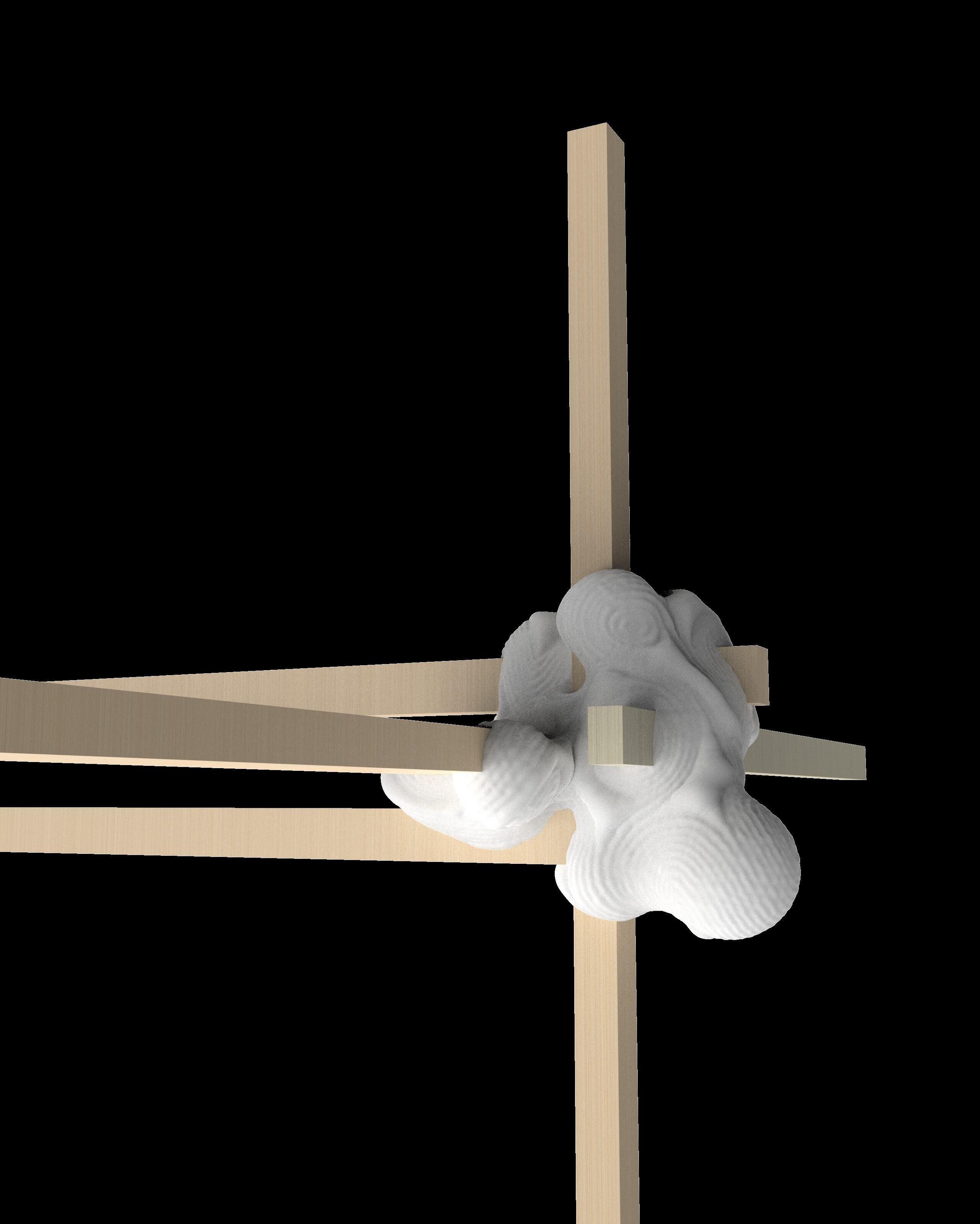
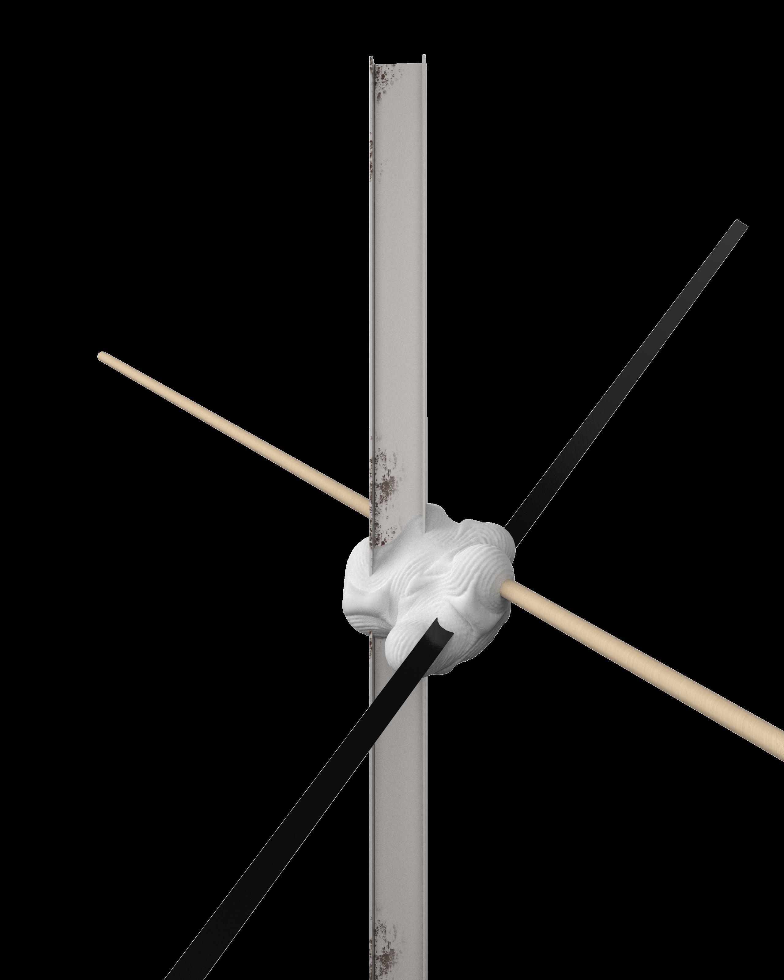
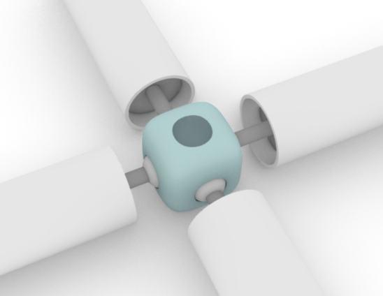
MULTI MATERIAL JOINT SPECULATIONS
Different profiles of materials can be encompassed by the customizable joints, allowing the design to modify freely with availability of materials. profiles are held together
JOINT SPECULATIONS
accommodate an extensive range of materials wood, metal, plastic, composites,
The joint system is designed to and more making it adaptable across scales and contexts. By varying the joint’s internal geometry and surface grip patterns, each connection can be tailored to the mechanical and frictional properties of the inserted elements.
These prototypes demonstrate how
a single joint typology can seamlessly integrate mixed-material assemblies, enabling hybrid constructions where reclaimed timber, steel tubing, and lightweight composites coexist in one structural framework
. This adaptability not only broadens design possibilities but also supports material reuse by allowing irregular or non-standard sections to be incorporated without modification.
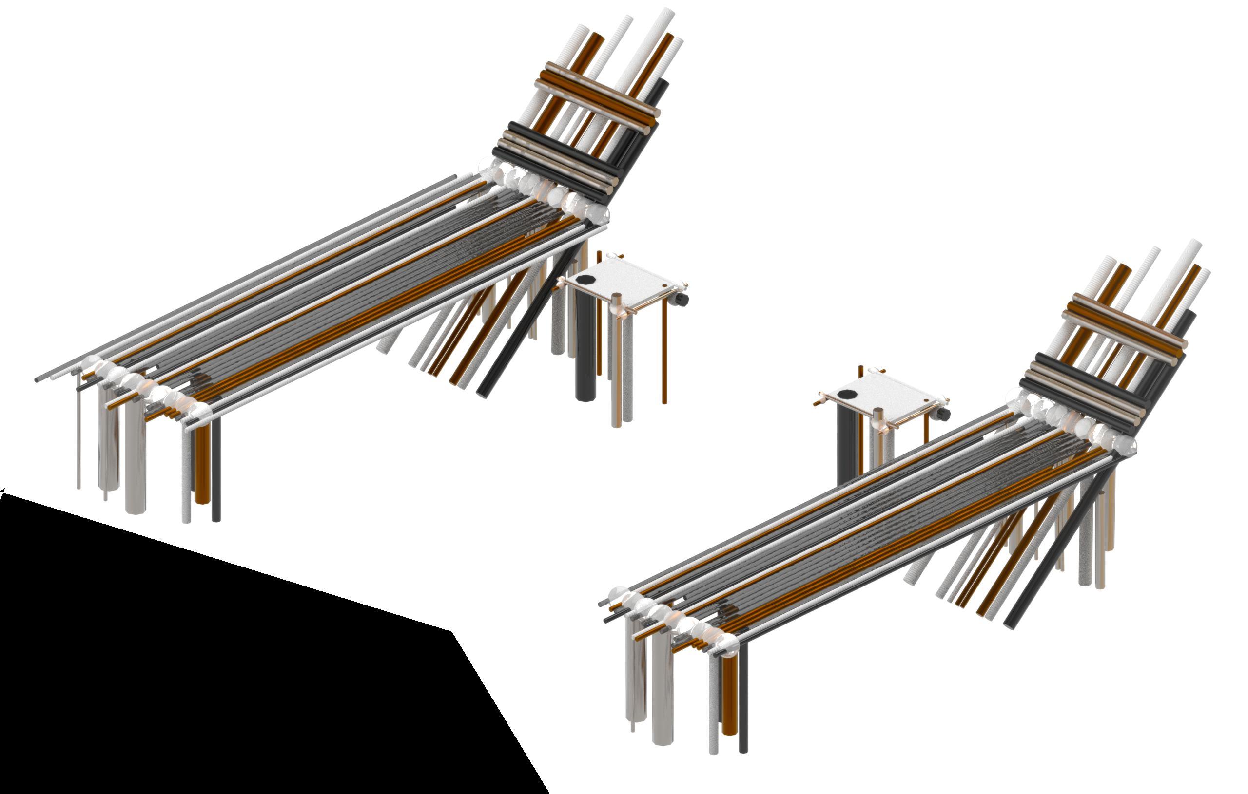
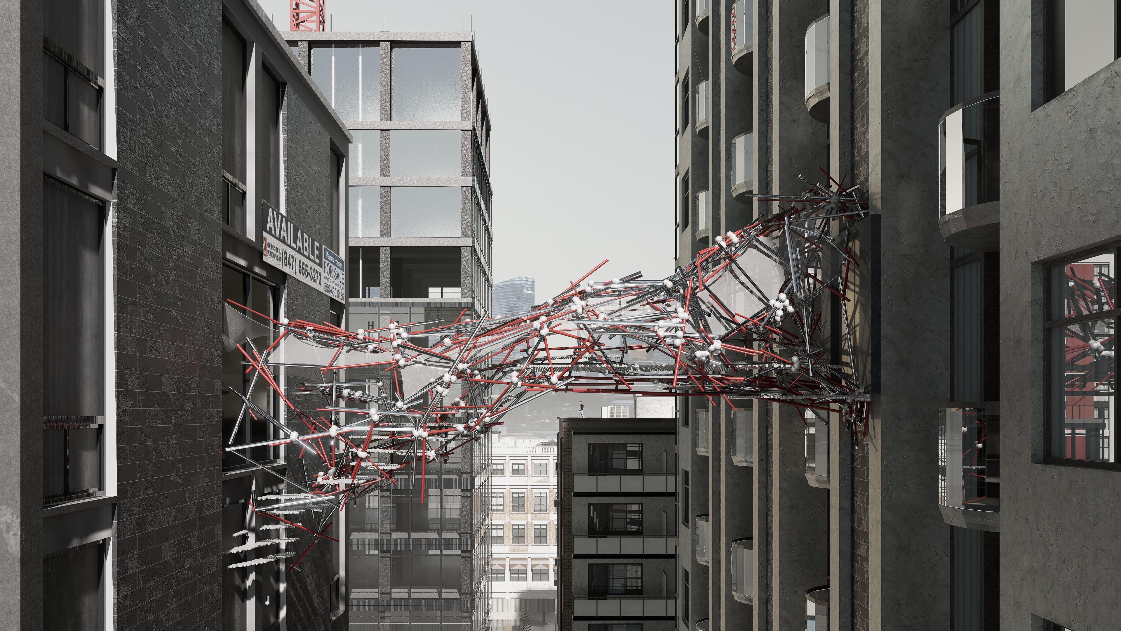
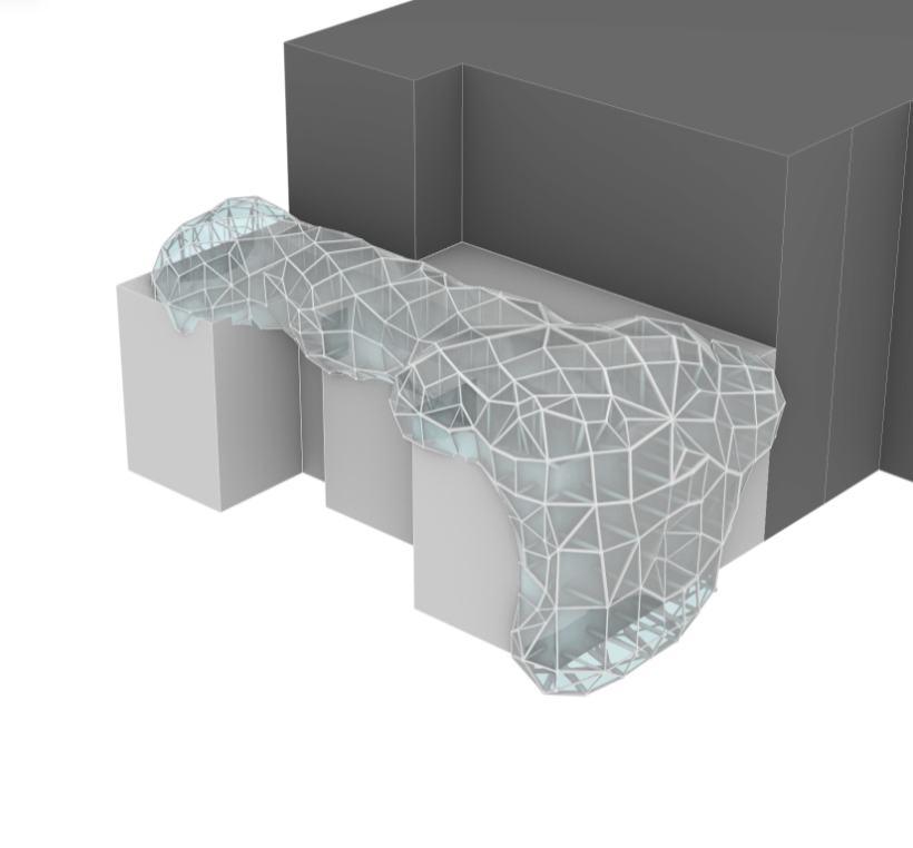
BRIDGE SPECULATIONS
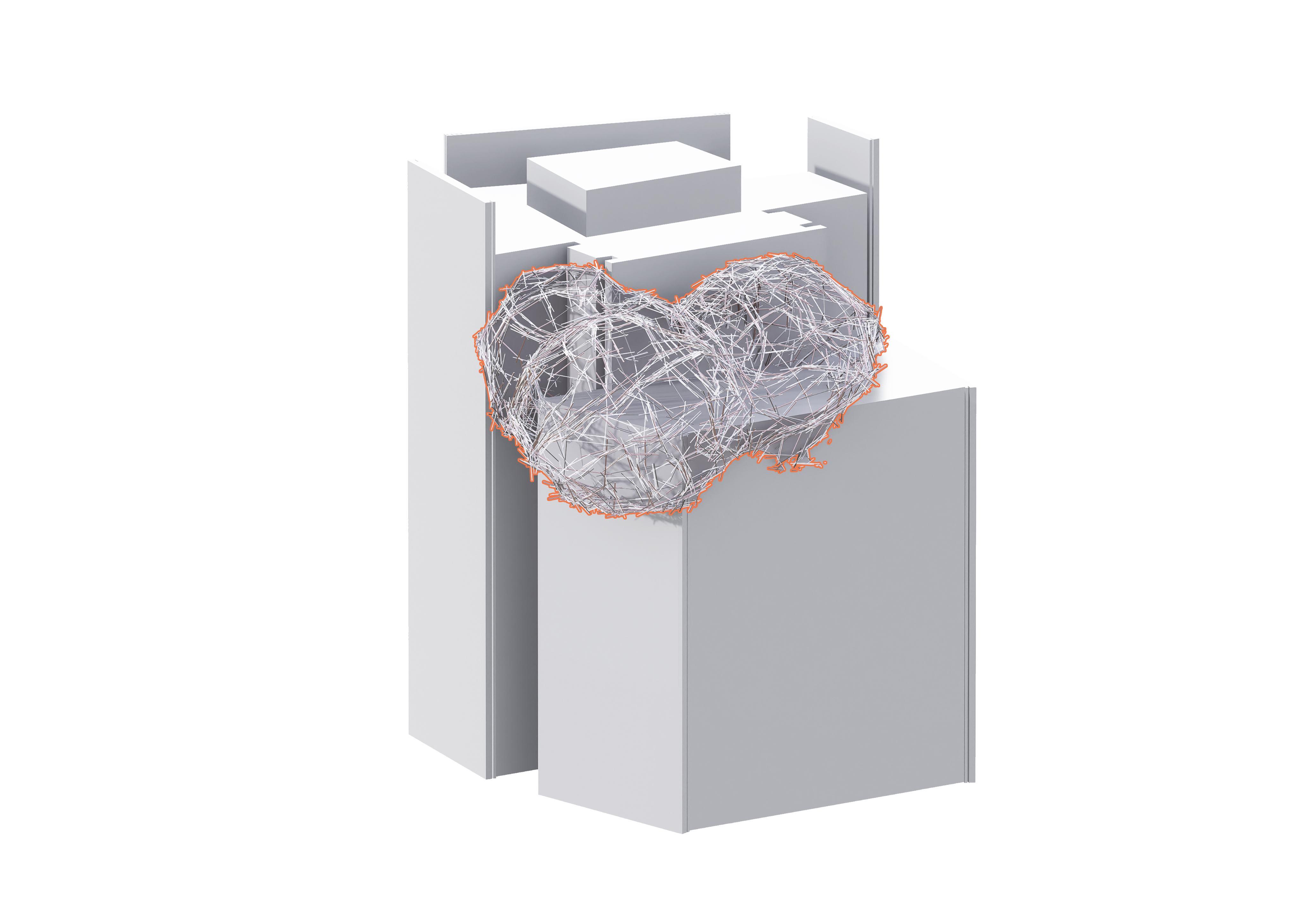
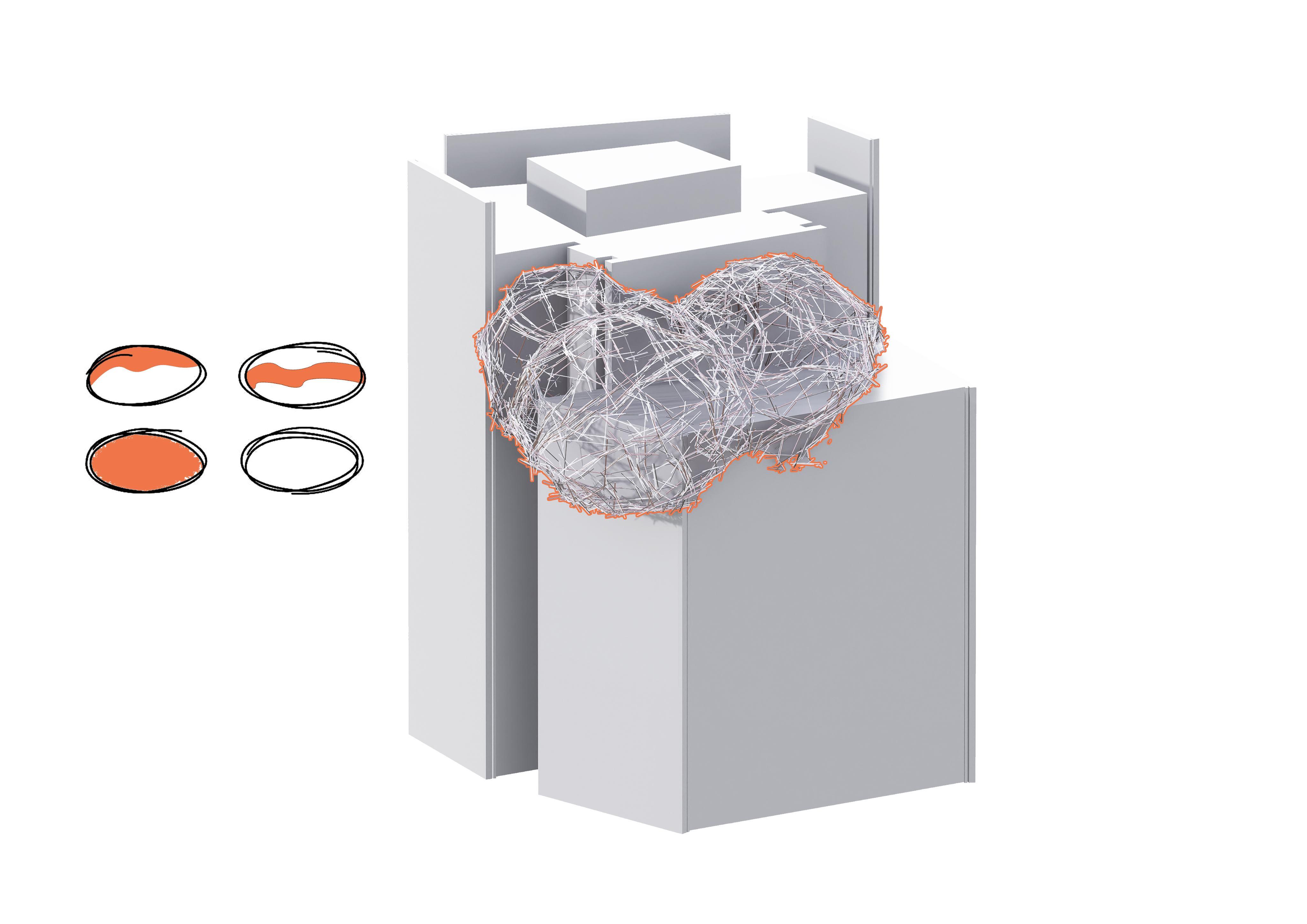
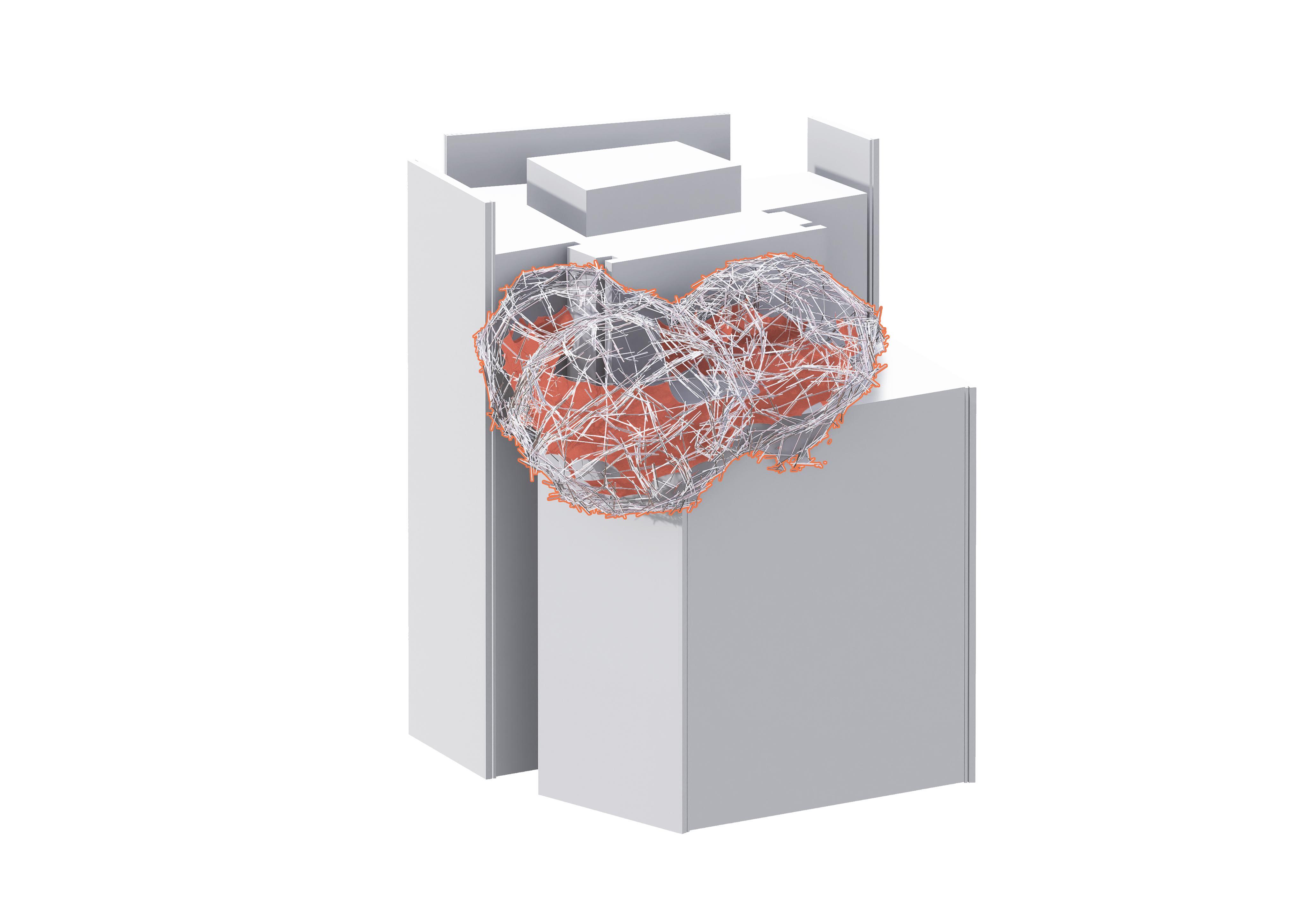
bridge speculation explores an adaptive structural system capable of spanning between existing buildings in dense urban contexts
structure demonstrates how modular components can be assembled into complex forms
This . The design integrates irregular, interwoven pipe geometries, responding to spatial constraints while creating a visually dynamic connection. By leveraging parametric design and database-driven fabrication logic, the suggesting possibilities for temporary or permanent pedestrian links.
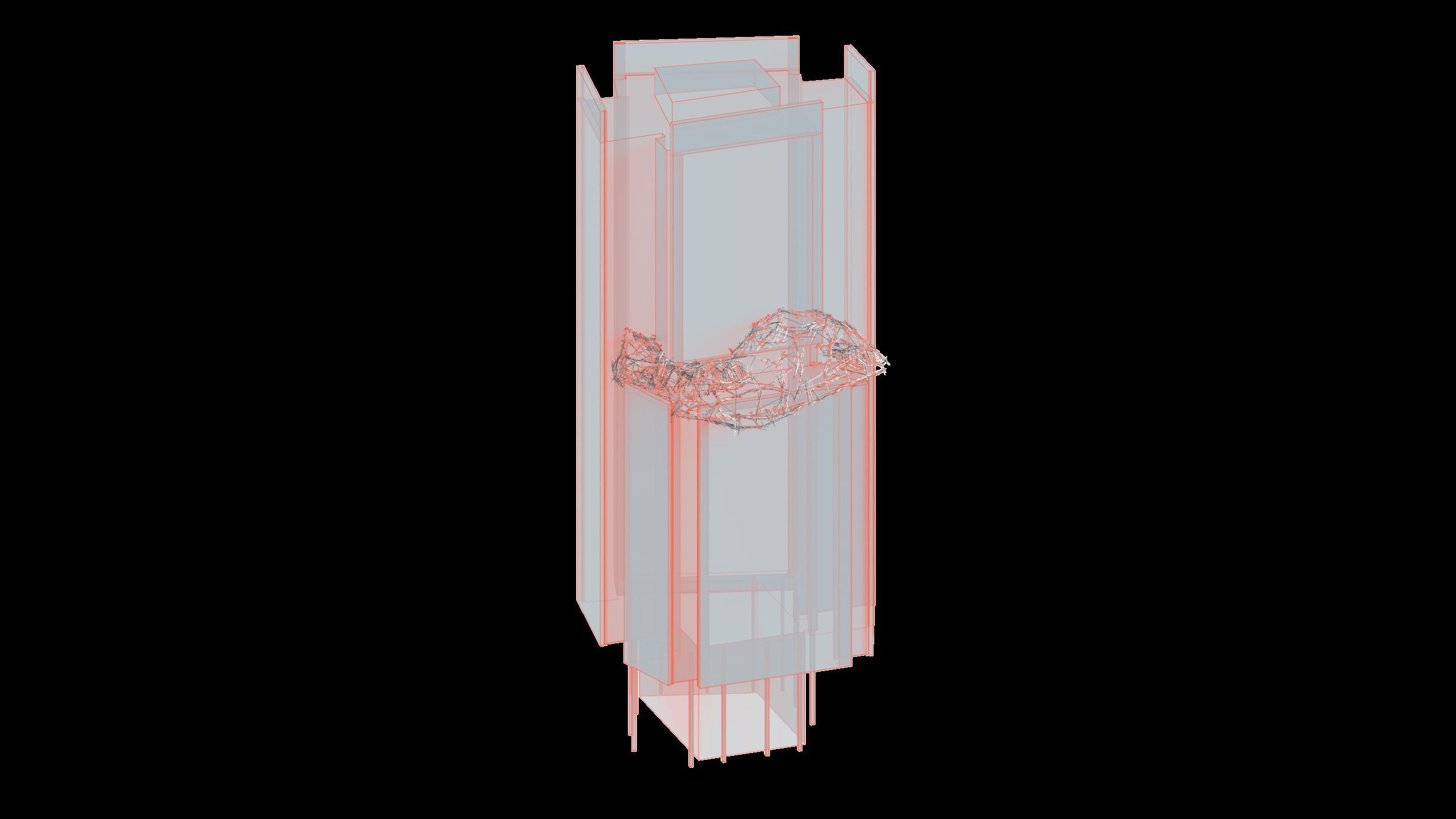
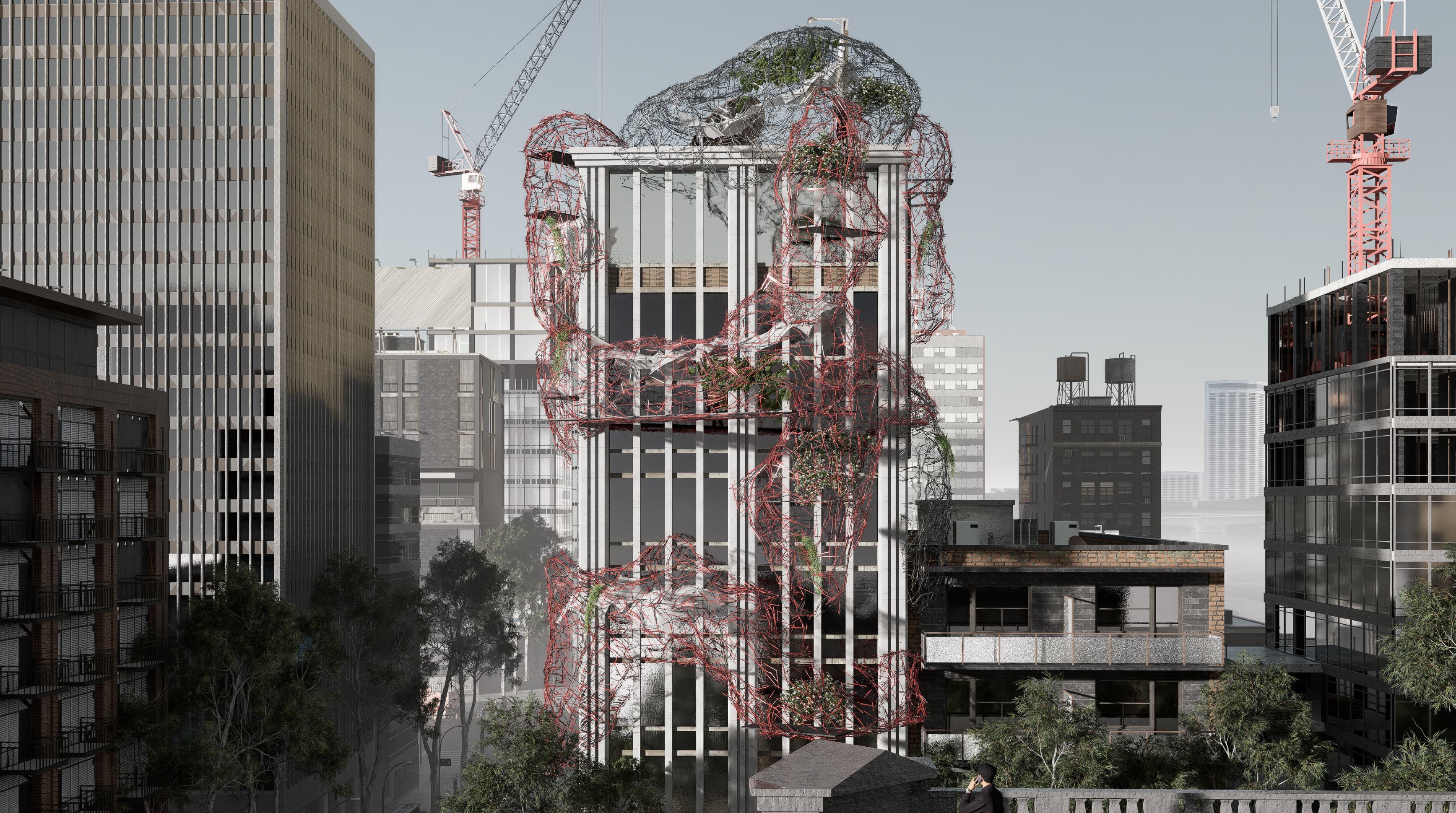
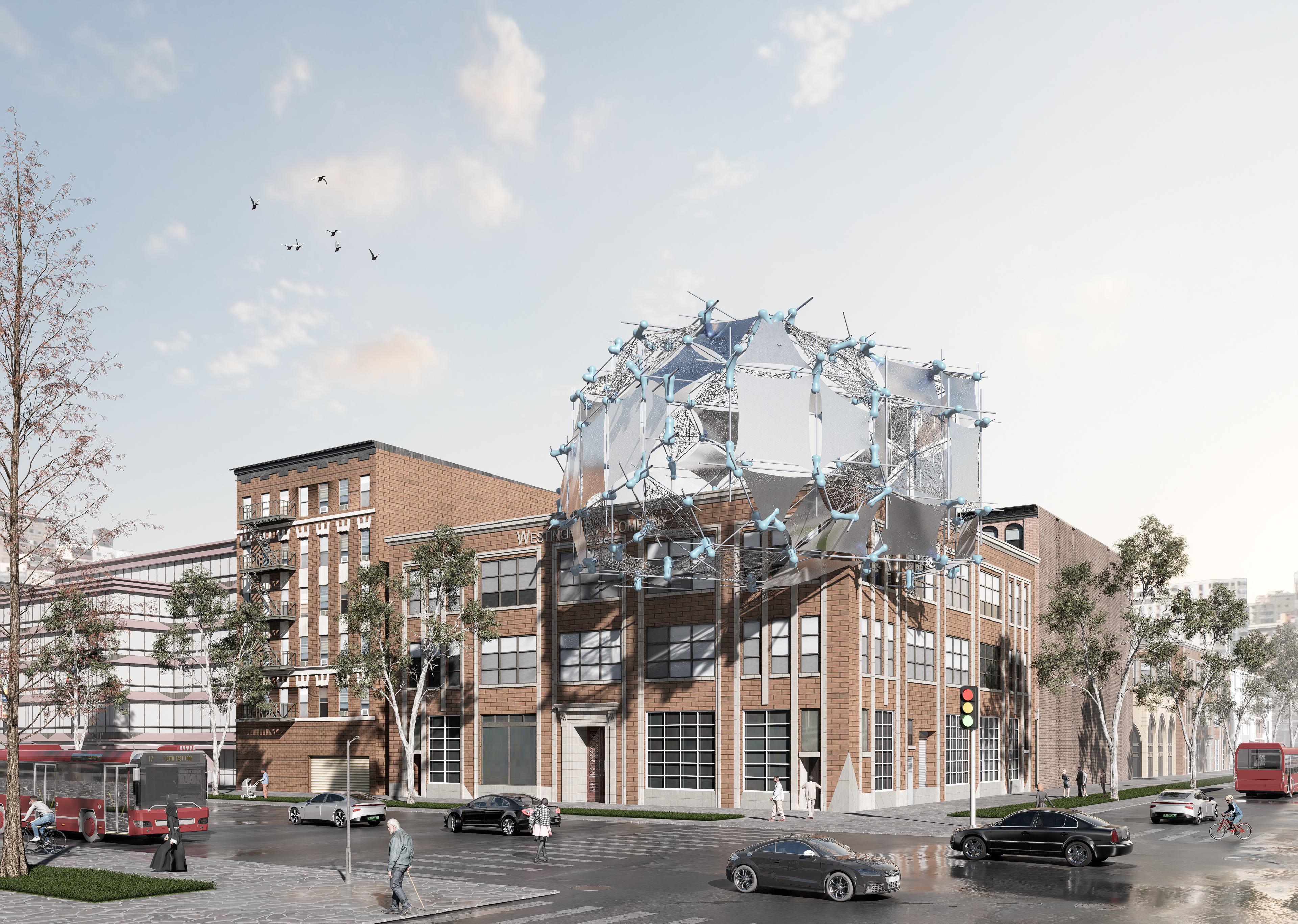
SKYSCRAPER SPECULATION
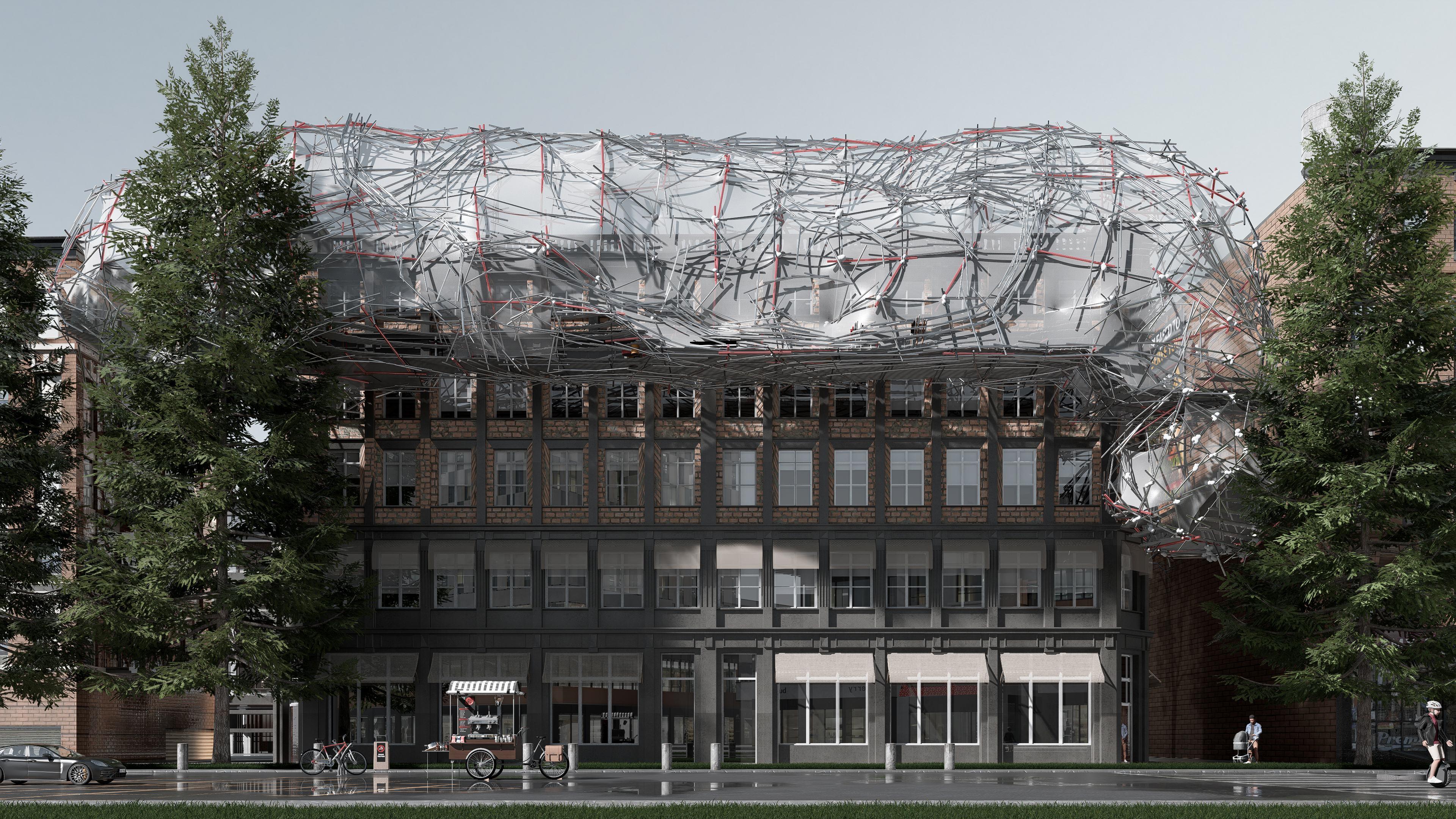
This skyscraper speculation envisions a vertical structure augmented by an adaptive, lattice-like exoskeleton woven from reclaimed structural components. , integrating greenery and creating layered terraces that blur the boundary between architecture and nature. Acting as both reinforcement and spatial extension, the structure adapts to the host tower’s geometry while introducing porous, inhabitable zones for circulation, vegetation, and shading.
The composition suggests a future where The framework wraps and climbs the façade high-rises evolve through material reuse to transforming rigid glass-andsteel silhouettes into dynamic, living urban organisms.
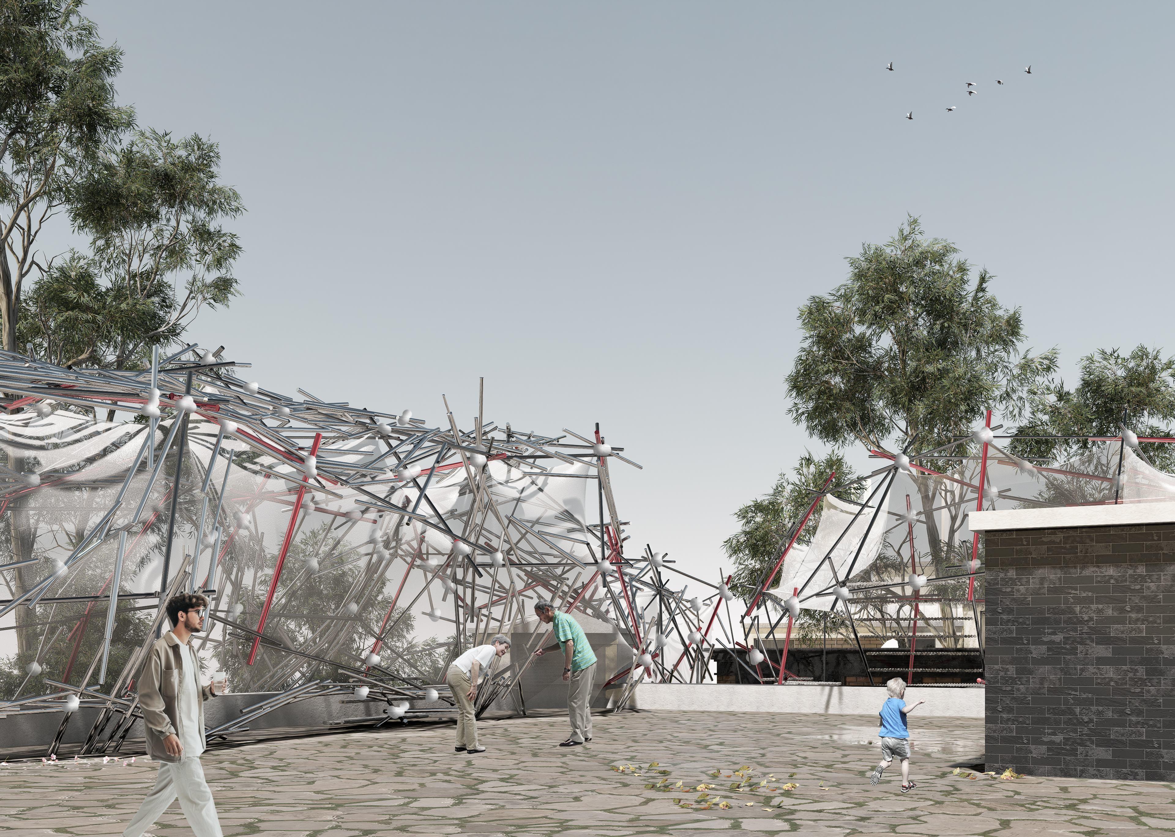
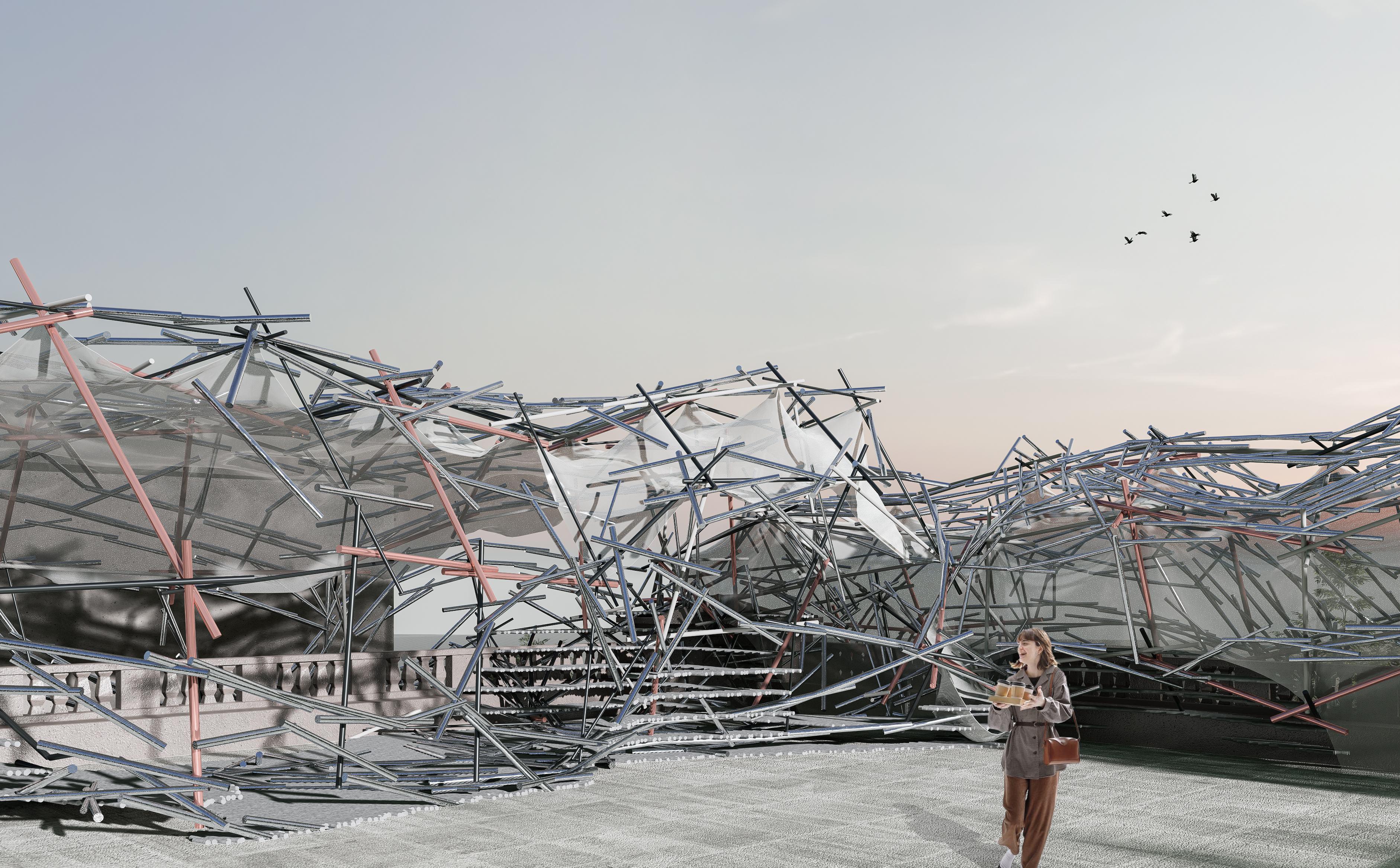
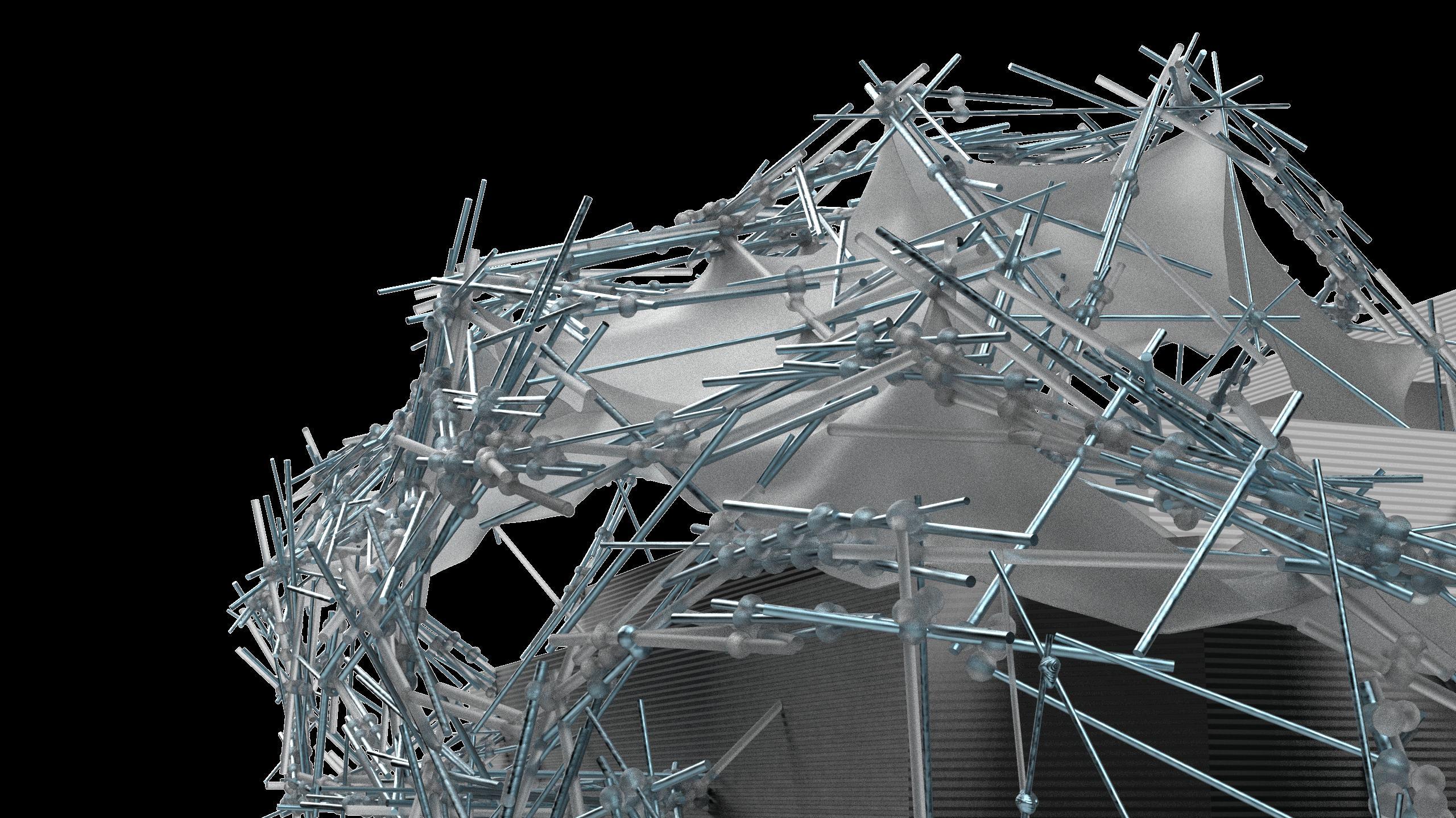
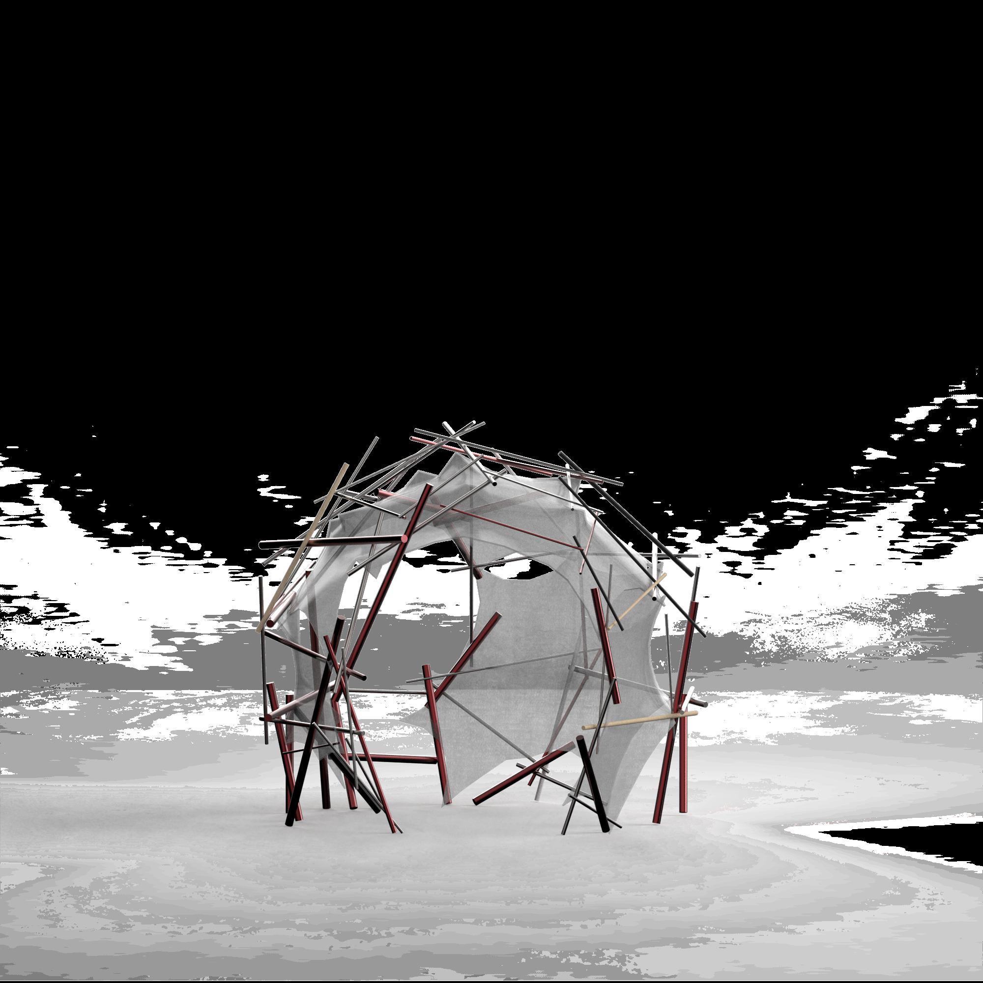
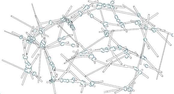
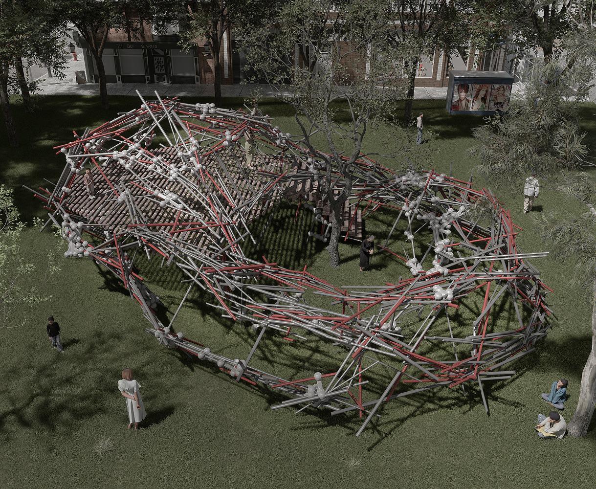
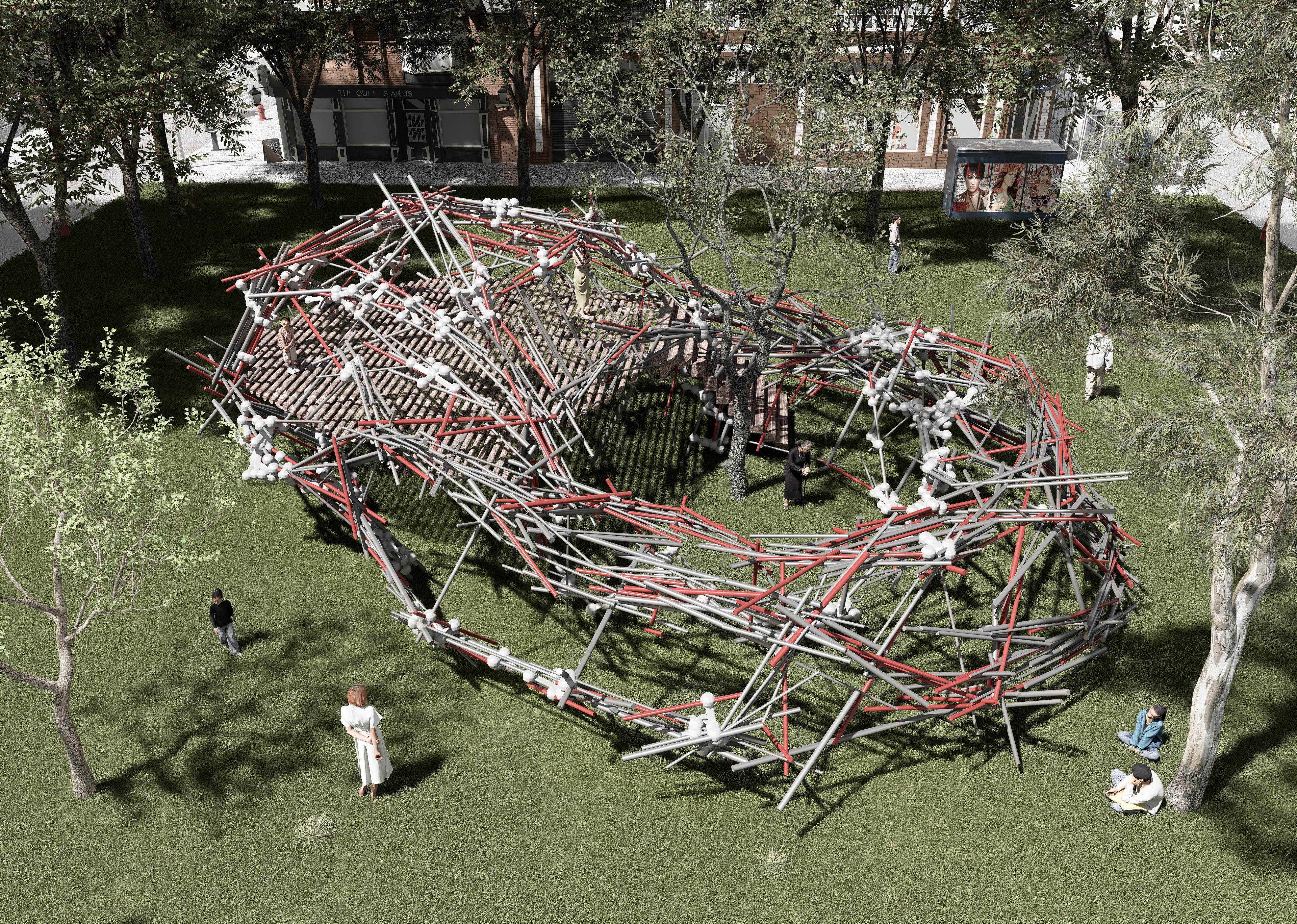
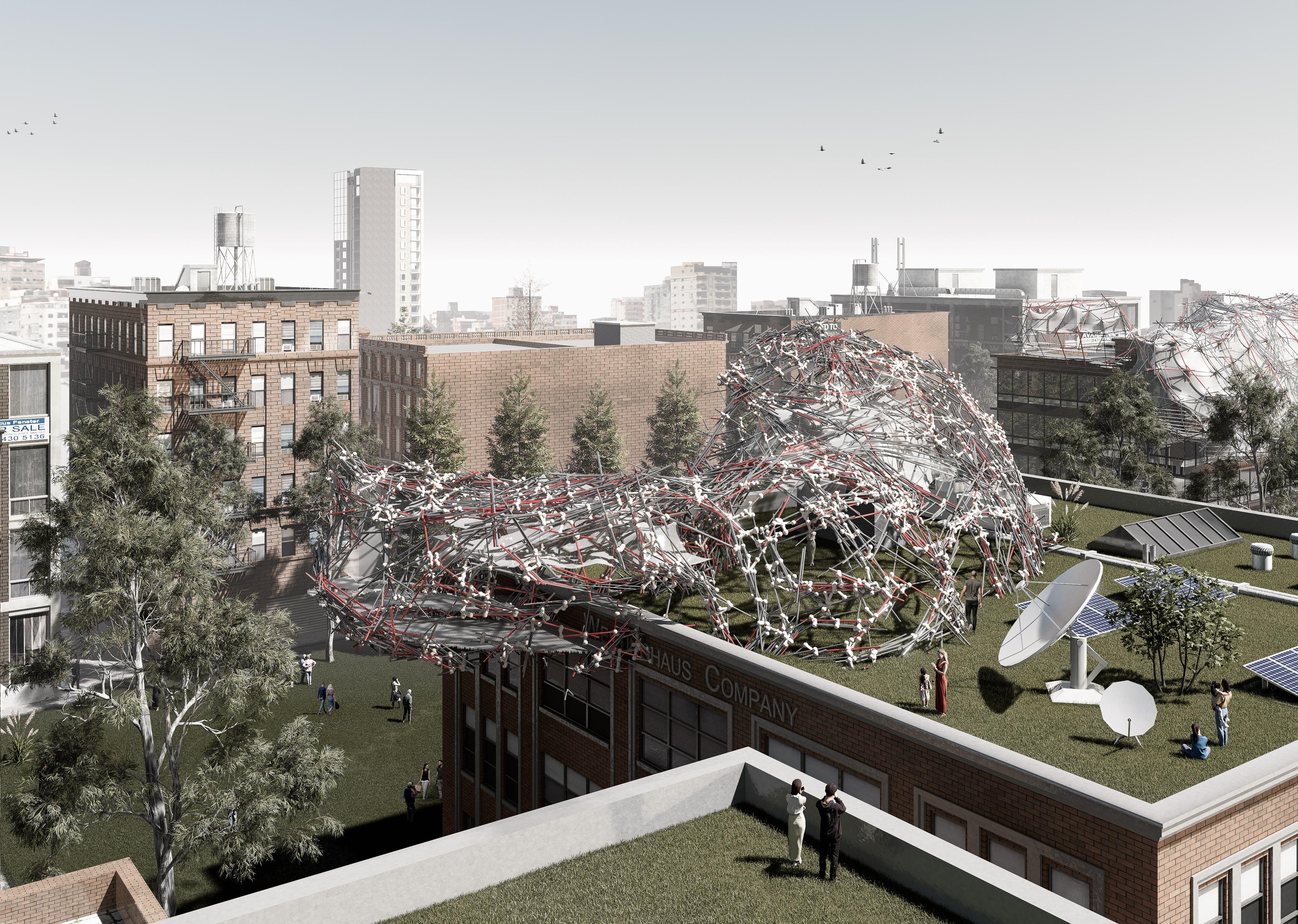
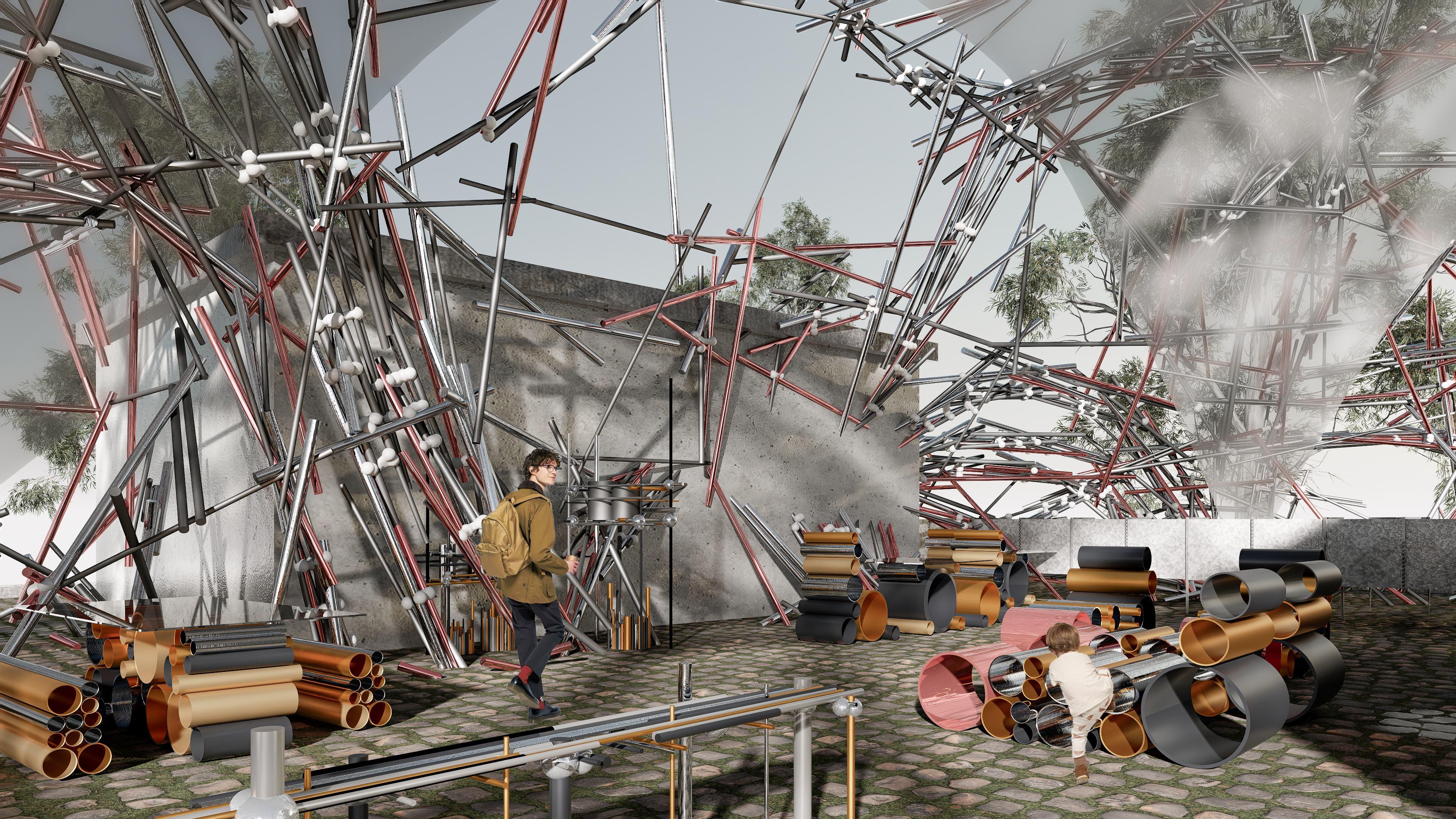
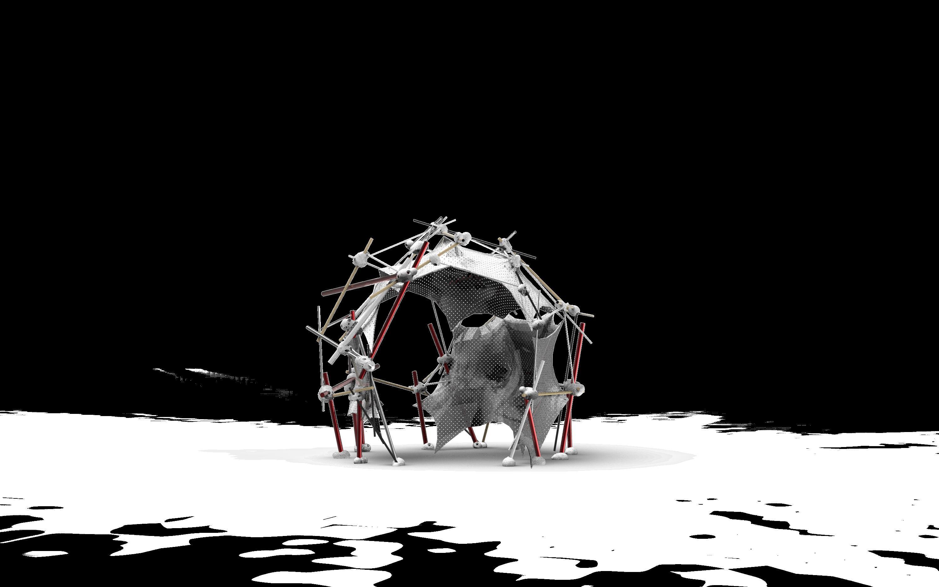
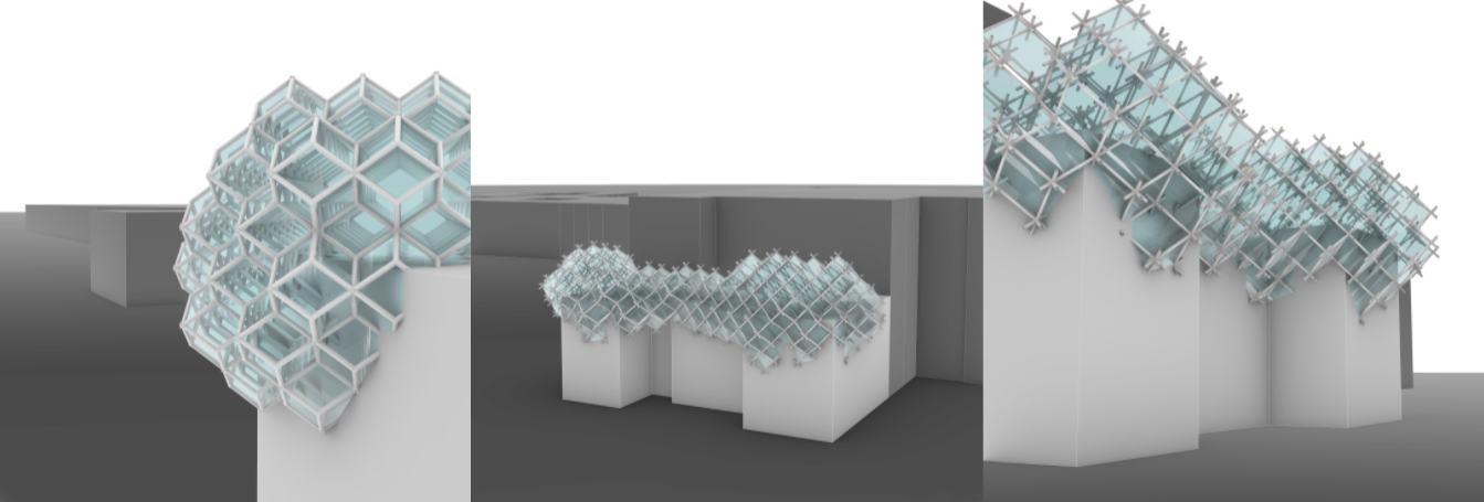
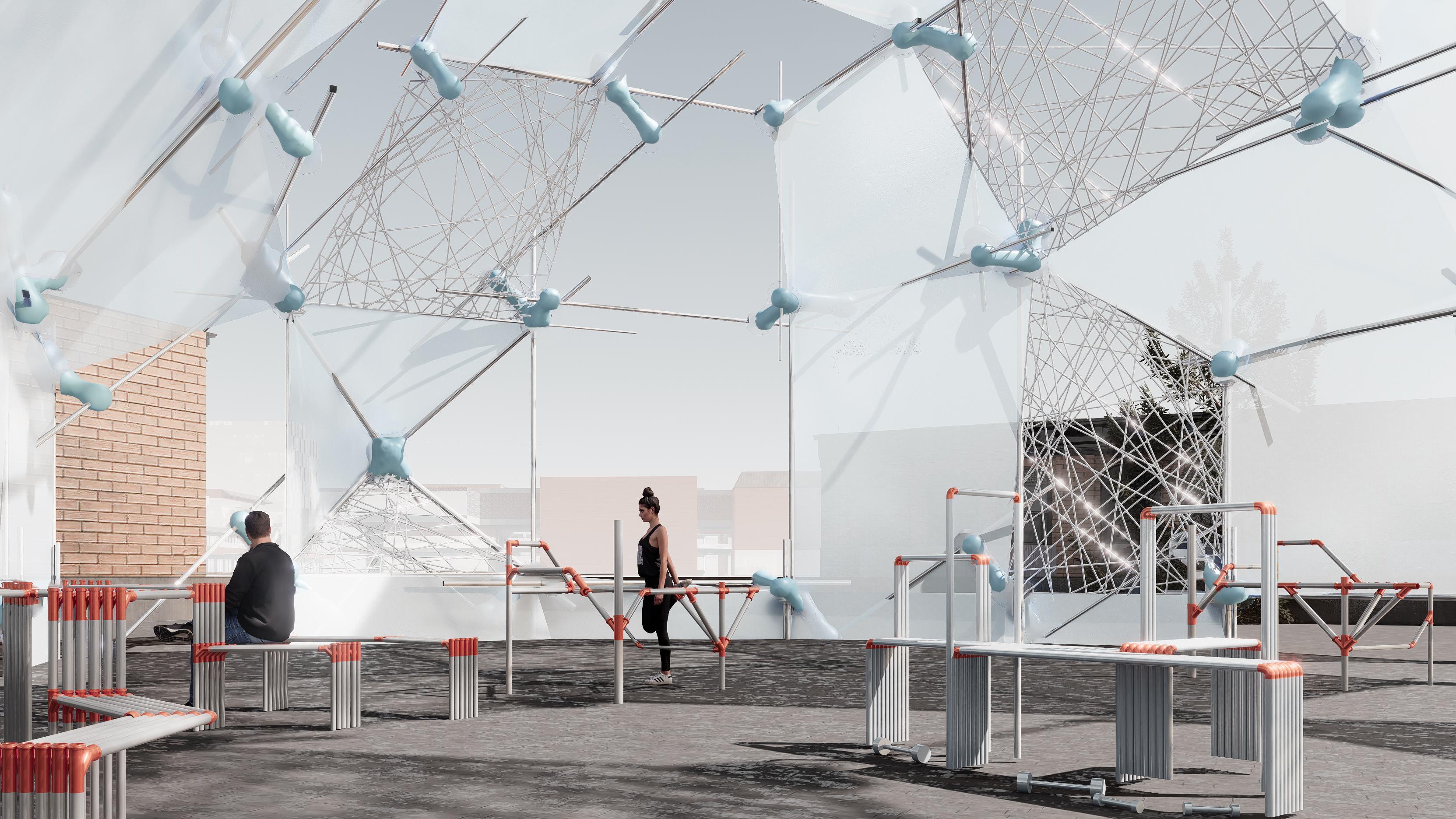
PAVILION SPECULATION
This pavilion speculation envisions a lightweight structural network embedded within a park
Its irregular yet intentional topology allows for both sheltered gathering spaces and open-air pathways , blending computational design precision with organic spatial integration.
Composed of an intricate lattice of different sized members connected by bespoke joints, creating varied pockets of enclosure and openness. , encouraging movement and interaction.
By situating the pavilion among trees, the design engages in a dialogue between built and natural environment. The concept explores the potential for generative structural systems to produce unique, siteresponsive and experiential richness.
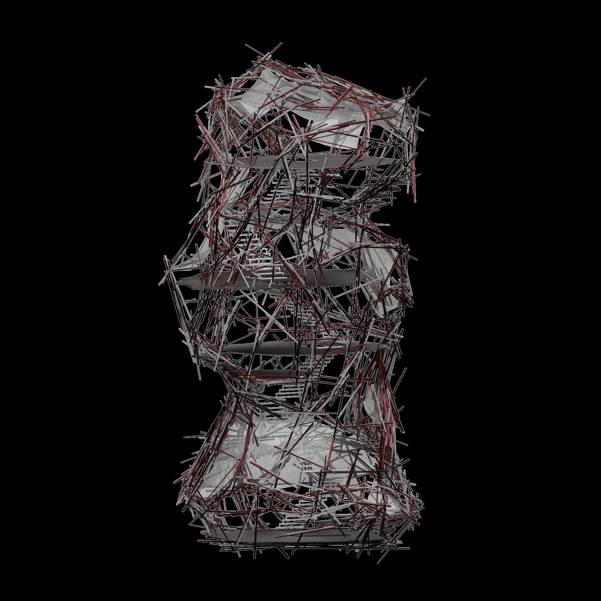
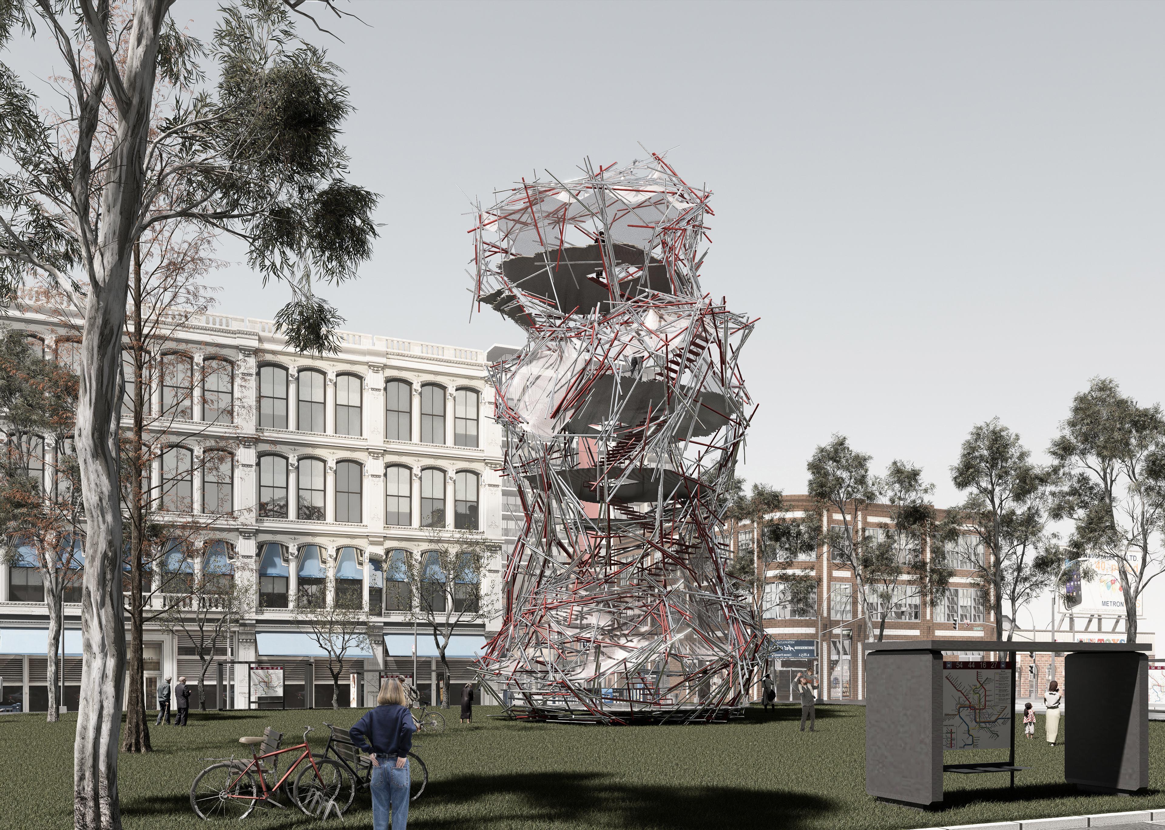
TOWER SPECULATION
This tower speculation proposes
The concept envisions future towers not as isolated icons, but as porous, participatory structures that accommodate both movement and pause.
a vertical framework that merges structural adaptability with public utility. layered platforms for resting, viewing, and gathering. encouraging interaction across multiple levels.
The design features a spiraling circulation path encased within a dense lattice of reused structural members. Acting as both support and enclosure, the framework introduces The structure negotiates between openness and protection, Its verticality not only adds visibility in the urban fabric but also offers new public territories that challenge conventional tower typologies.
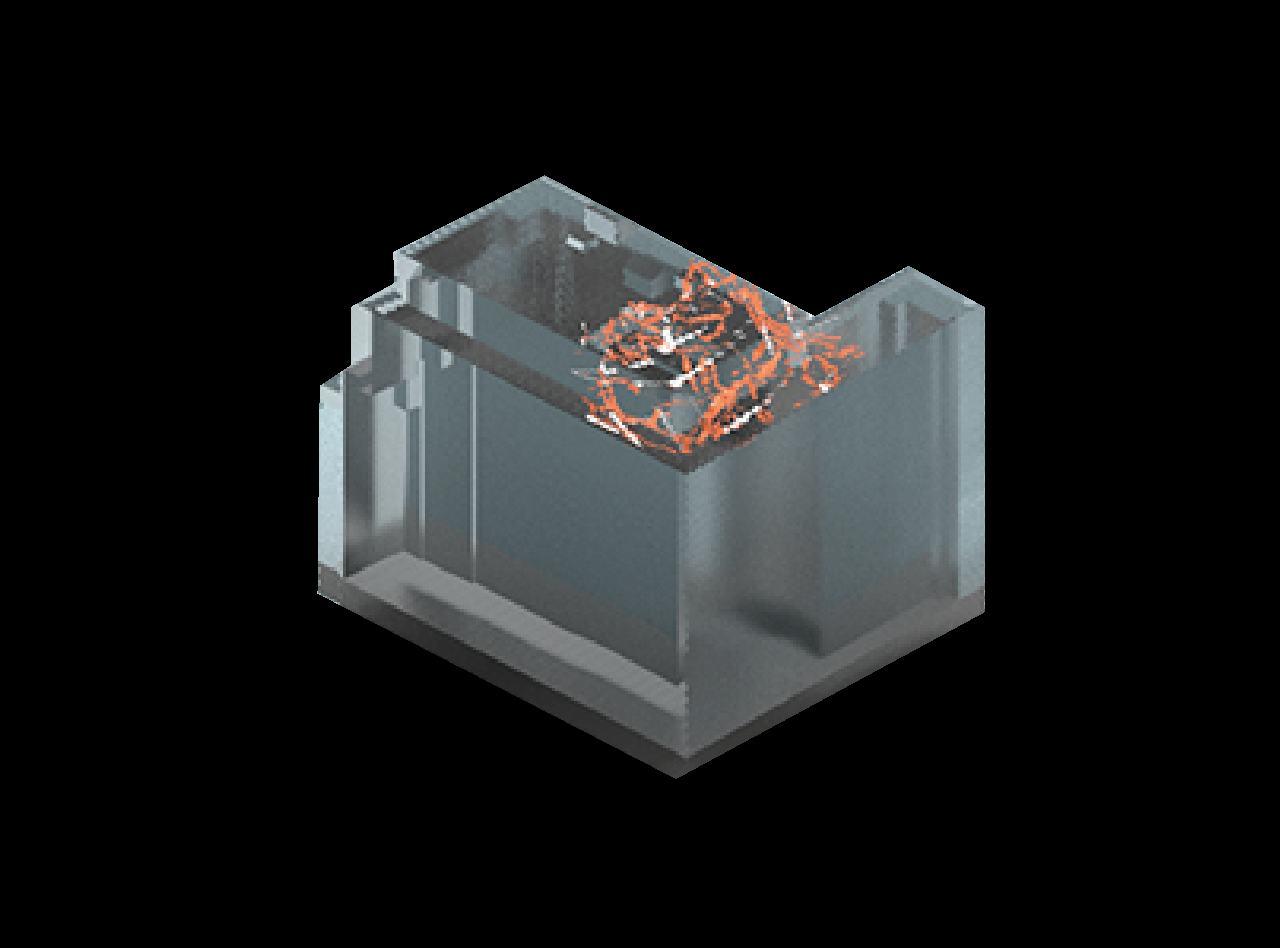
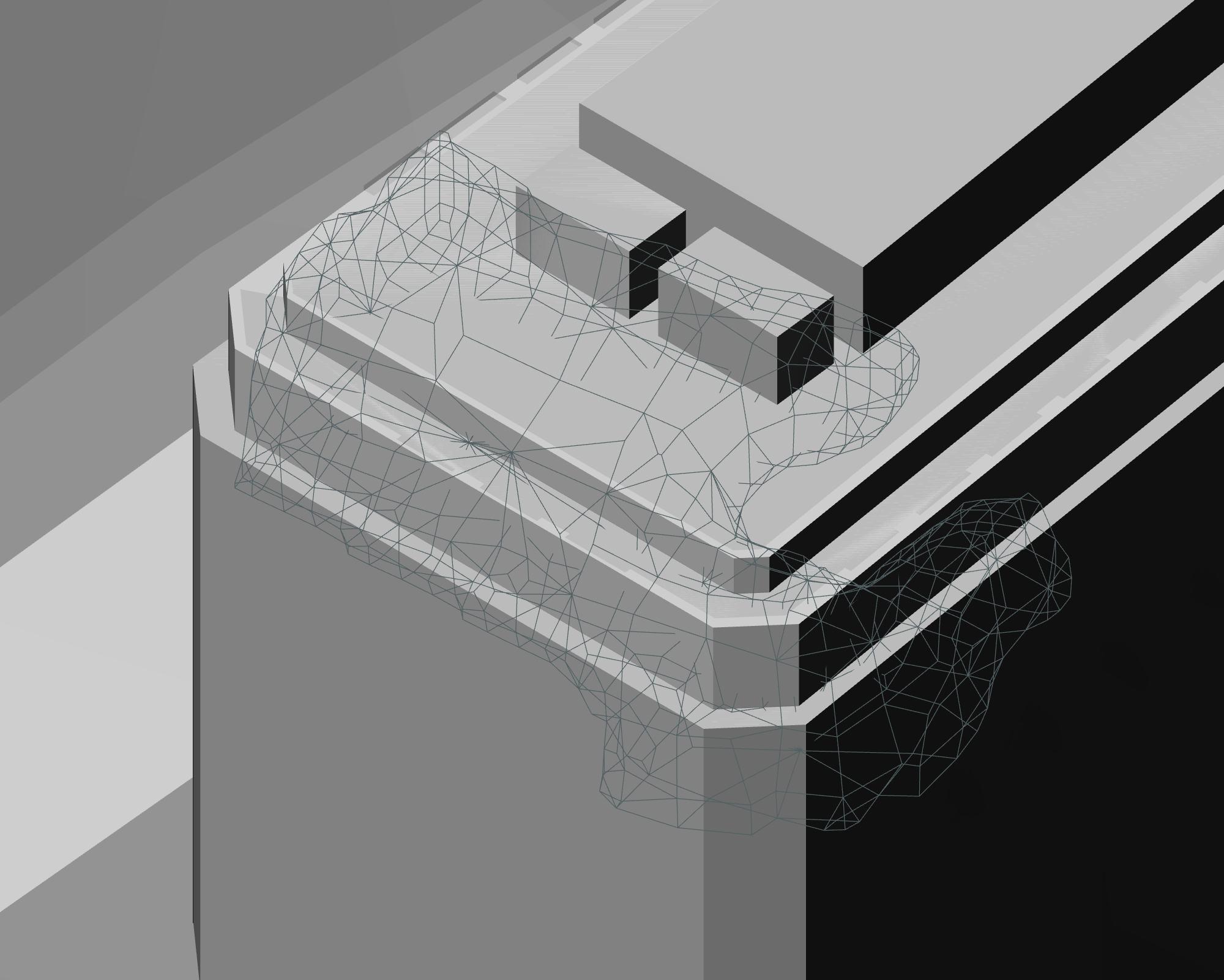
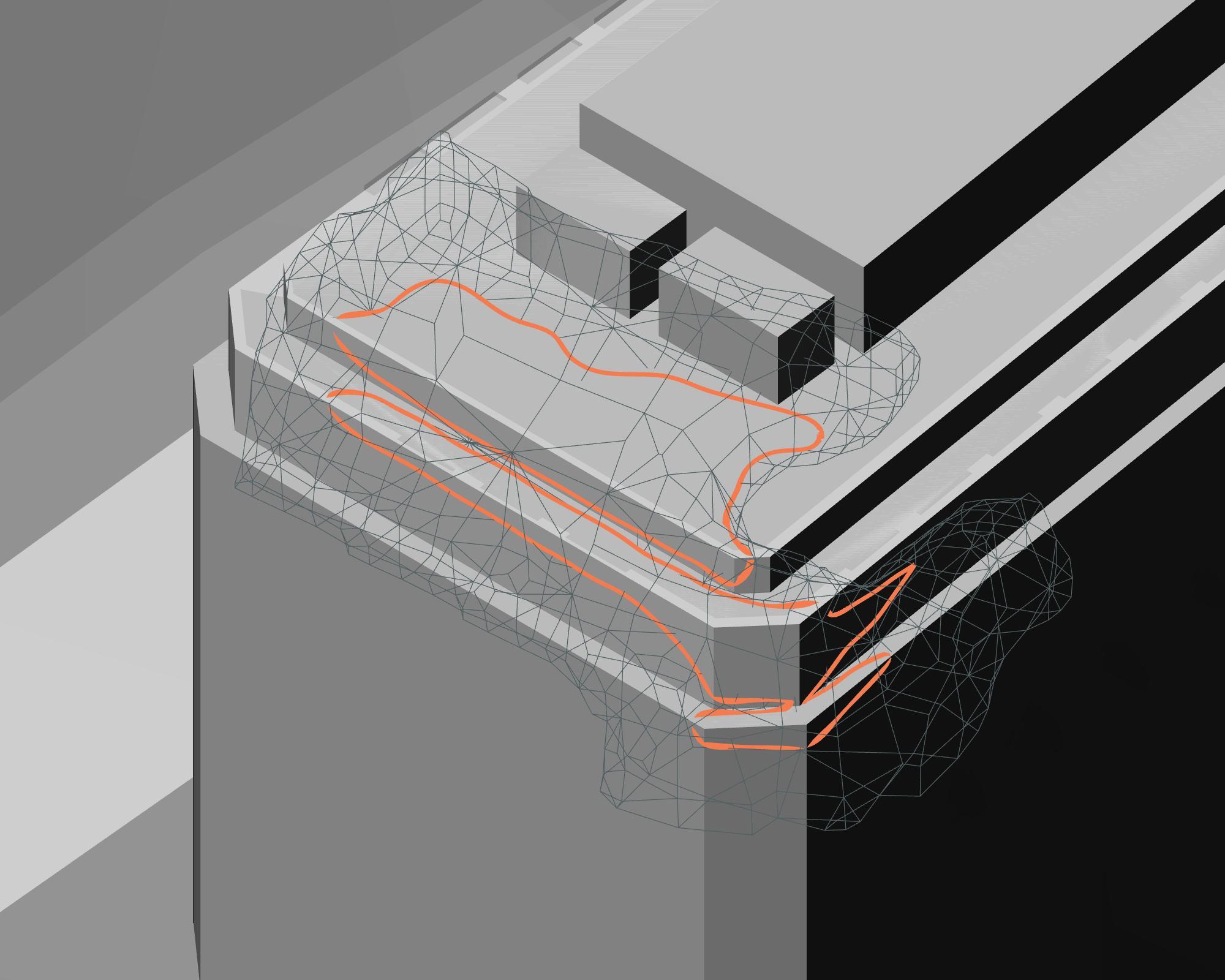
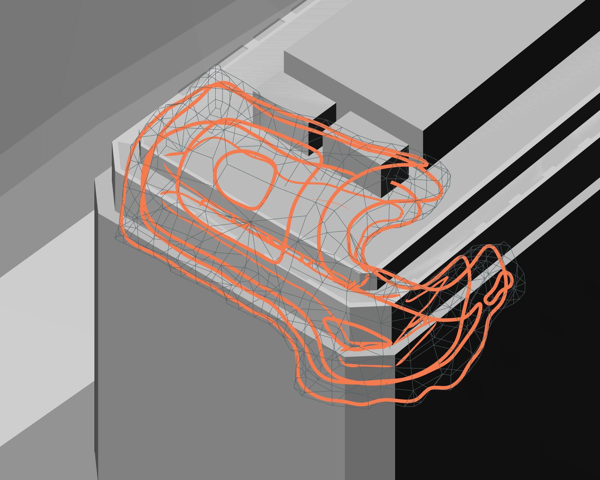
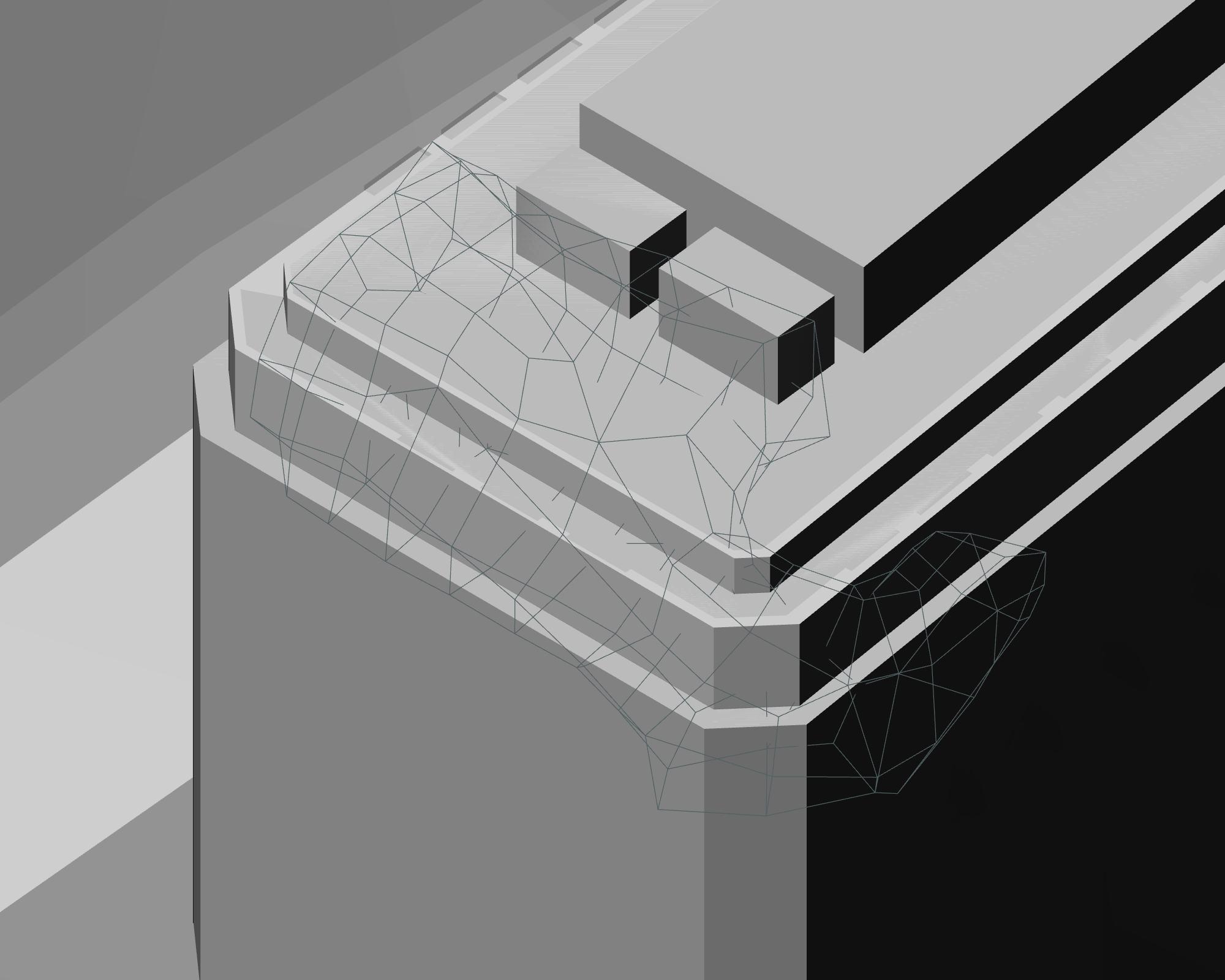
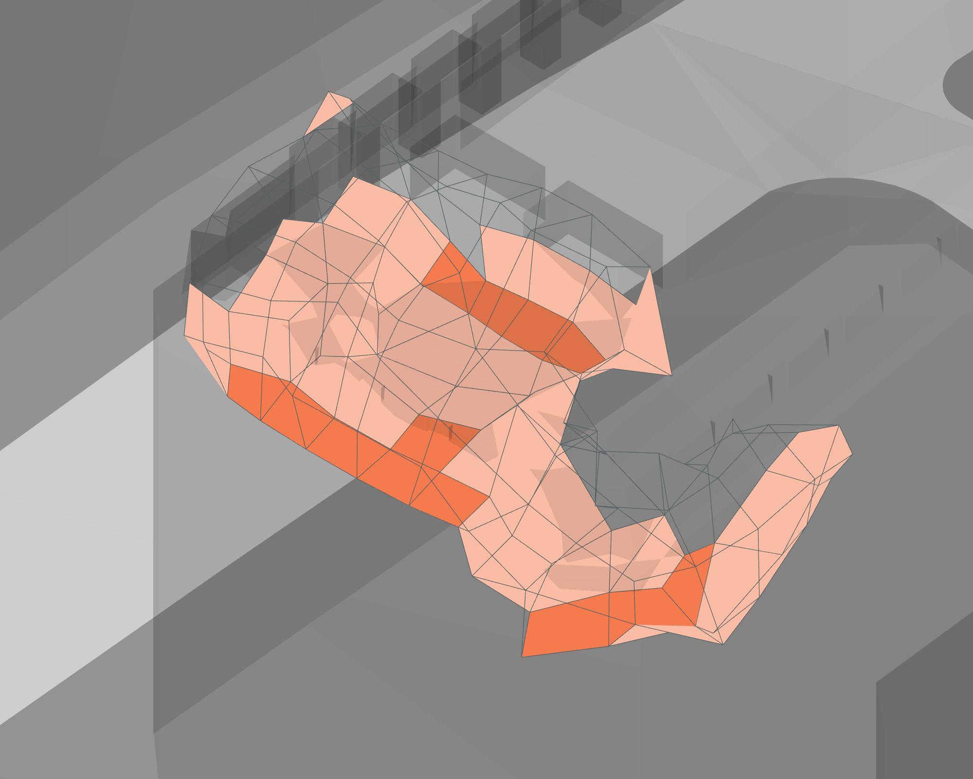
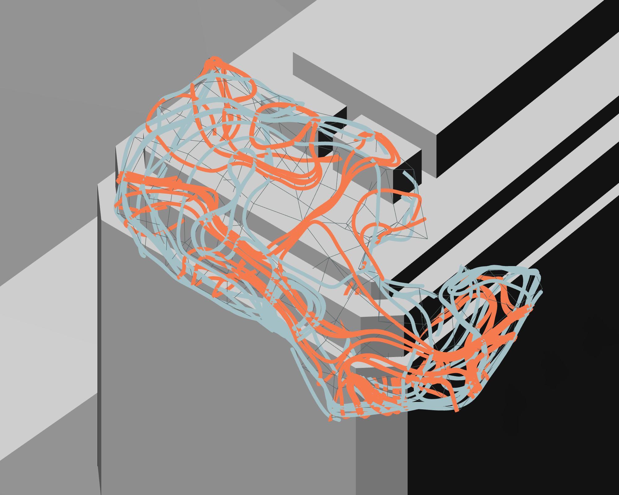
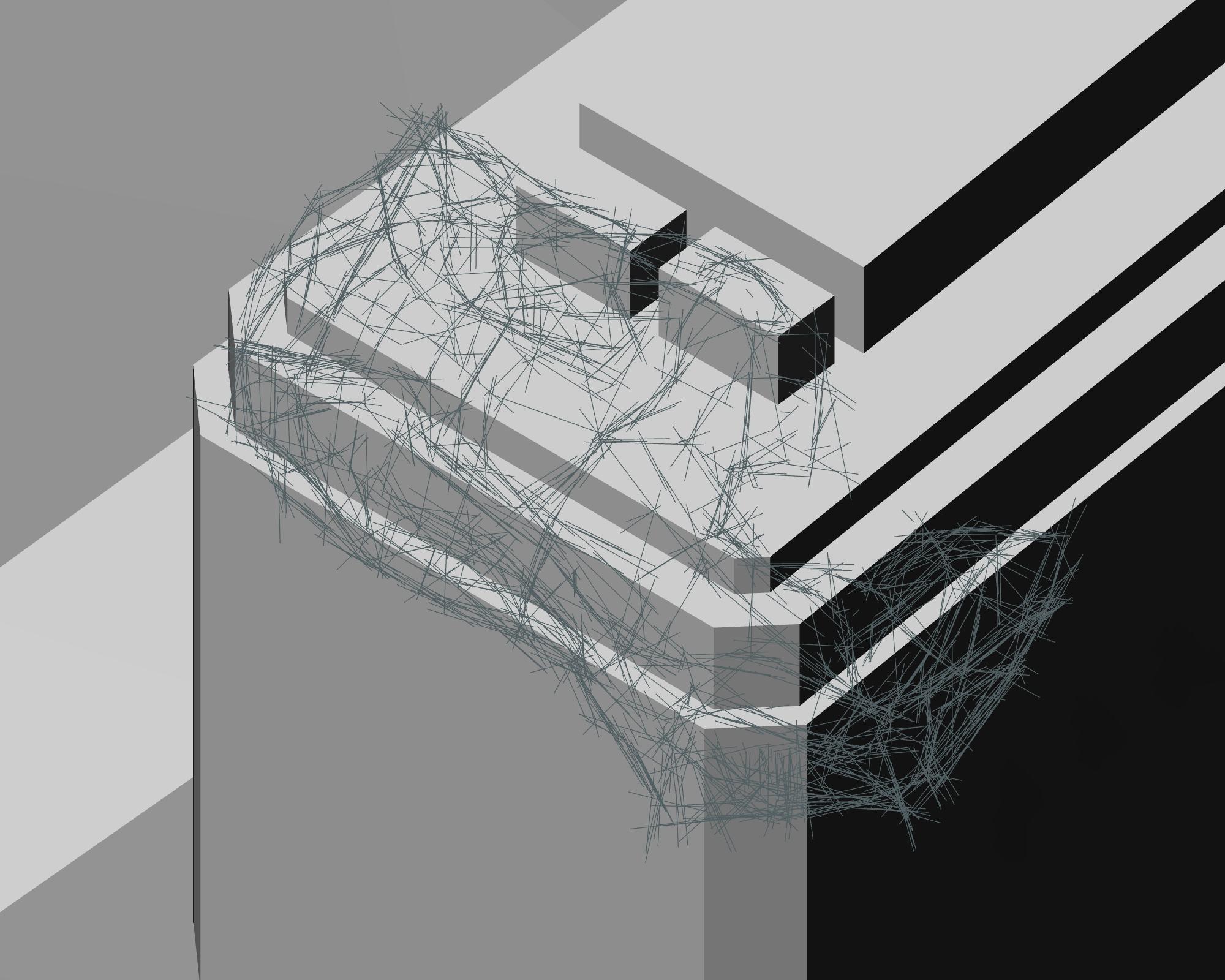
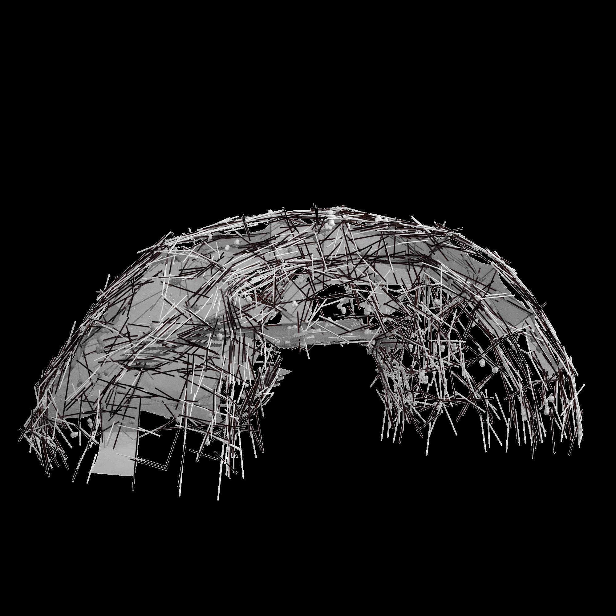
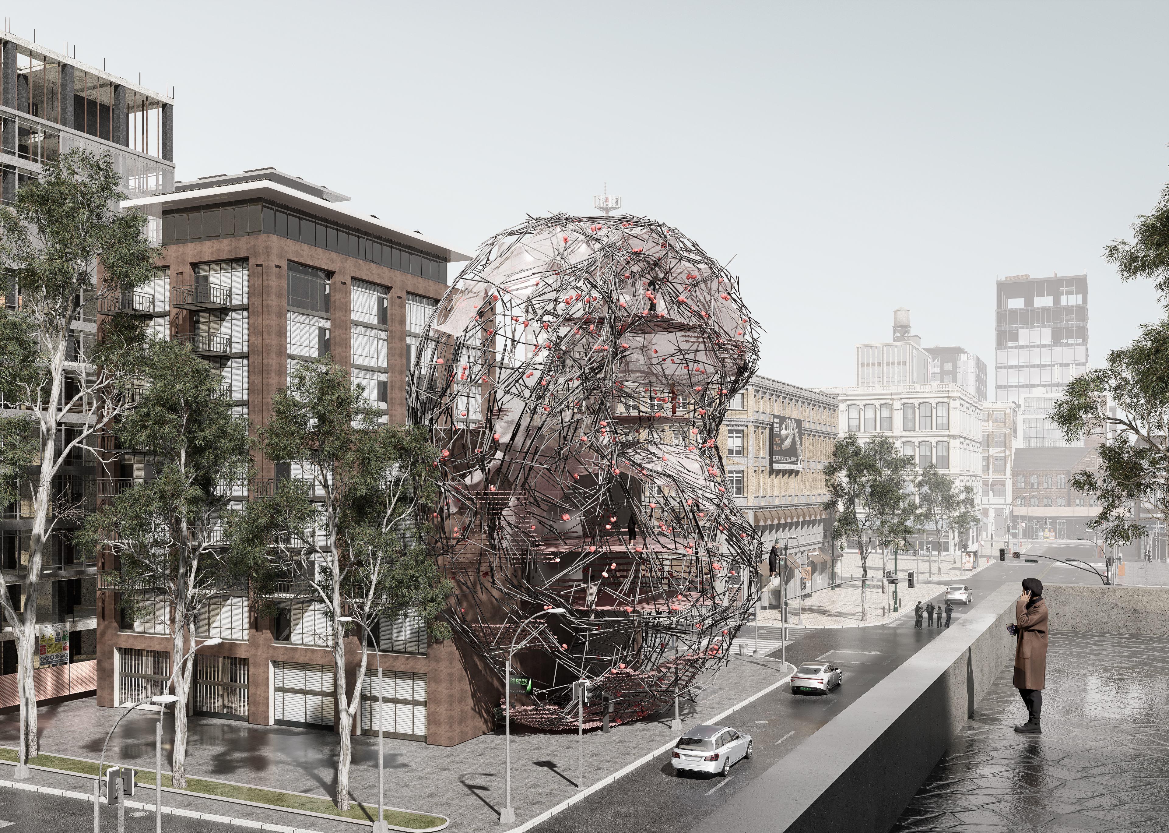
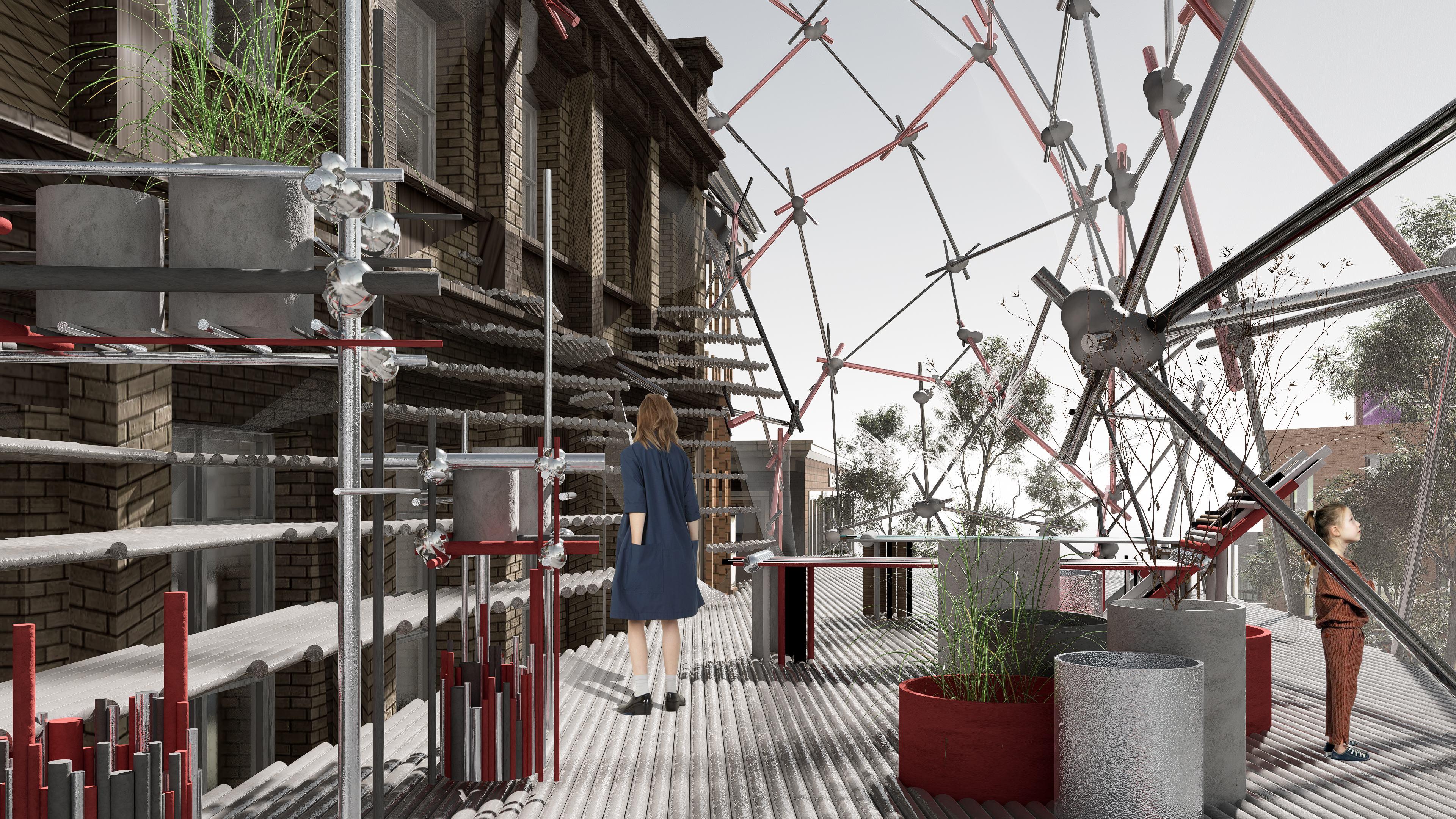
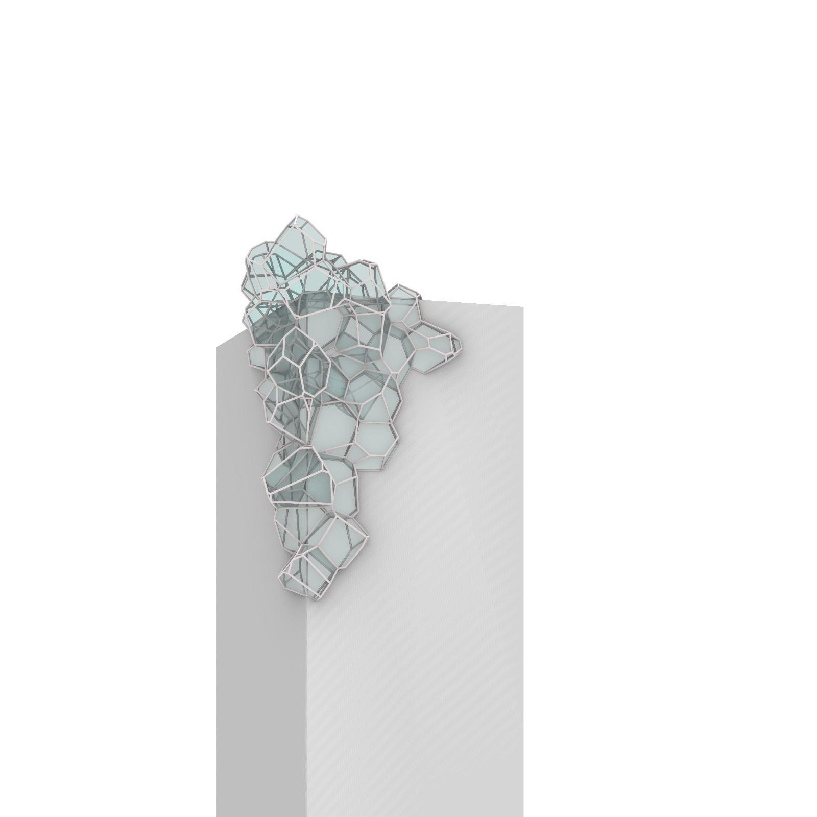
CORNER SPECULATION
This corner speculation as active architectural agents. and creating transitional spaces between interior and exterior. Through layering structural meshes and inhabitable pockets, the design transforms the façade into
By reclaiming the threshold as a space of encounter, the intervention proposes a typological shift—
The porous configuration enables light, air, and circulation, redefining the relationship between form and function at the street level.
reimagines underutilized building edges A hybrid exoskeleton wraps around the corner volume, softening the rigid geometry an interactive buffer zone.
where the building’s corner becomes a spatial mediator between structure, city, and community.
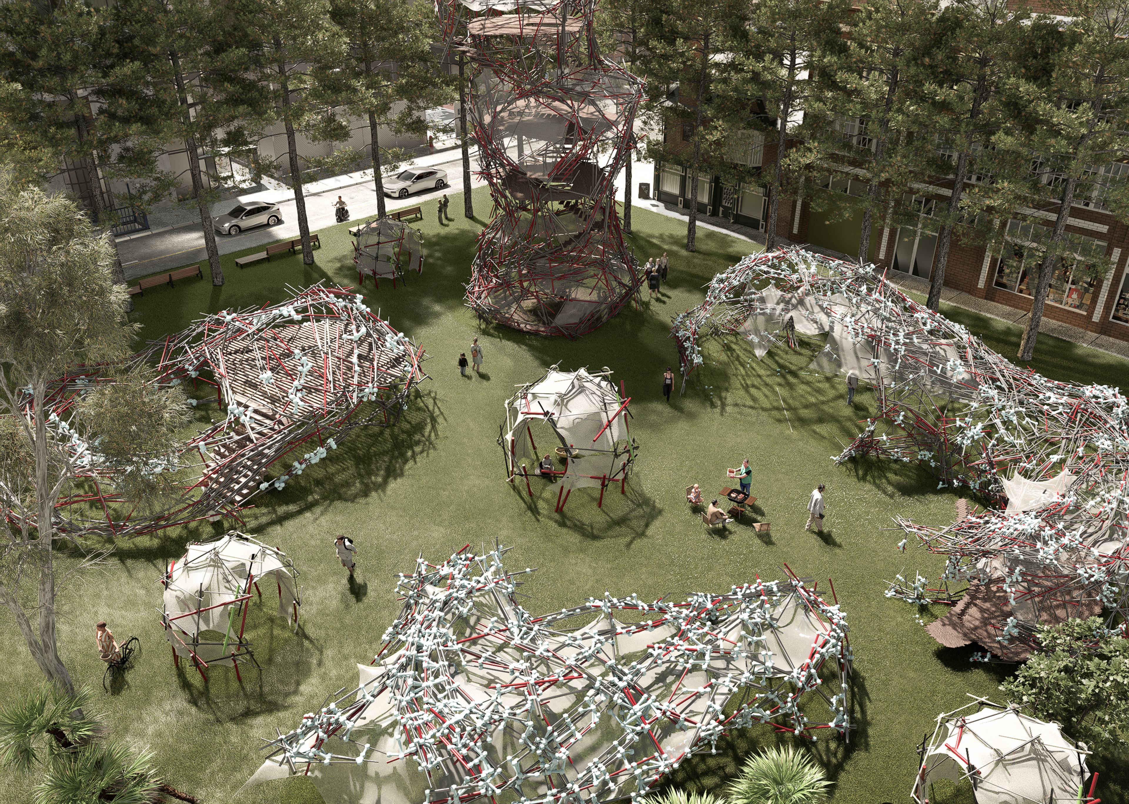
GARDEN SPECULATION
This garden speculation imagines forming a Each individual element—ranging from towers to shaded pavilions, shares a common formal language yet The aggregation of these components creates a heterogeneous environment of open lawns, semi-enclosed shelters, and connective corridors. encouraging movement, gathering, and interaction beneath and between lightweight, lattice-like geometries.
a landscape composed of clustered speculative structures, collective system embedded within an urban park. varies in scale, porosity, and enclosure.
The garden becomes a porous field of activity,
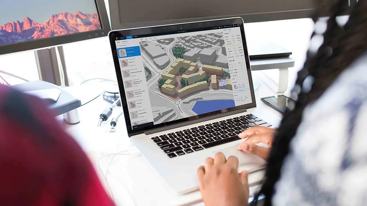
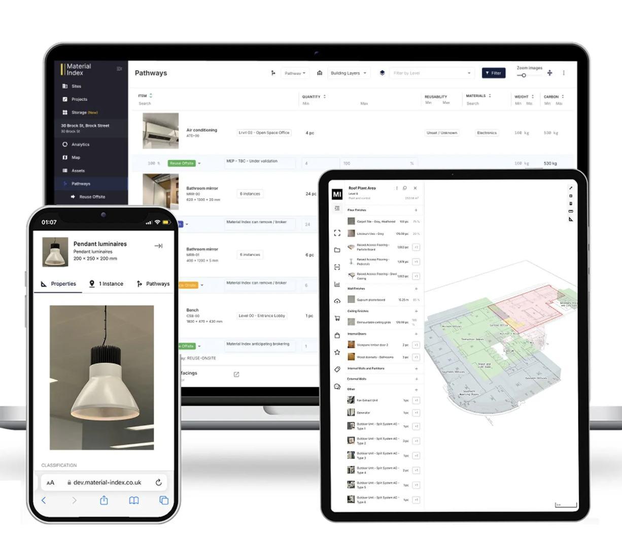
DIGITAL PLATFORM
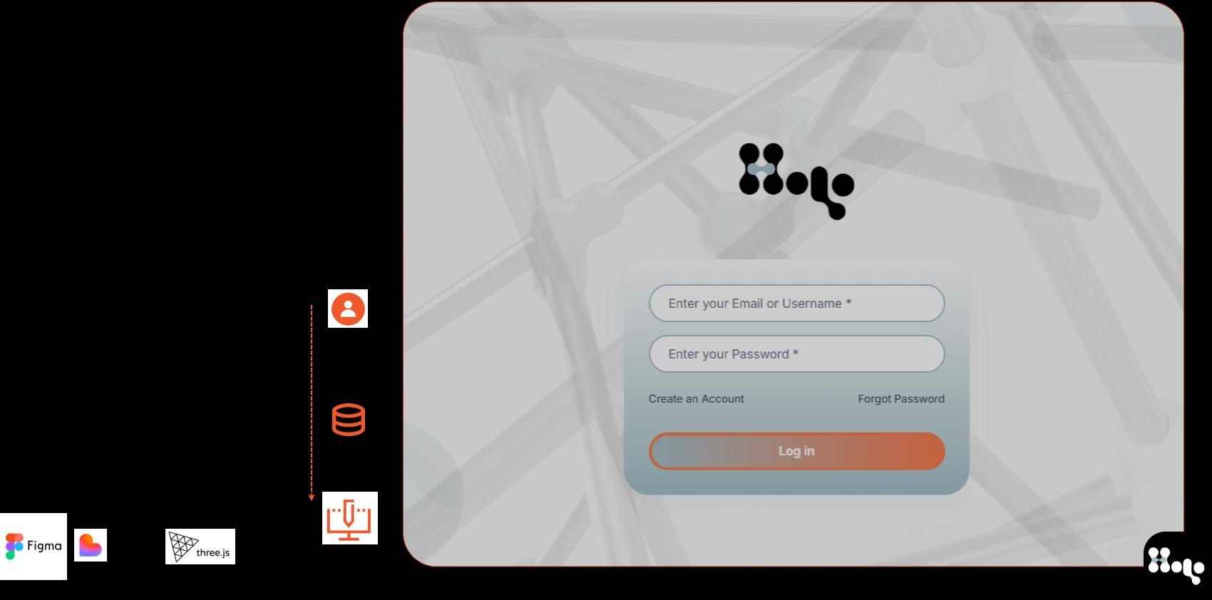
USER INTERFACE FRONT END
DIGITAL PLATFORM
The platform integrates a material
database, environmental analysis tools, and
machine learning algorithms to
use reclaimed materials to . Users can enter to design or as
suppliers looking to upload materials. generate site specific structures
Refer to appendix pg. 120-122 for more content.
STEP BY STEP USERFLOW
Hololab’s design workflow is
mapped through two interconnected flowcharts:
The first captures the, outlining the decisions, actions, and pathways taken when engaging with the platform.
user-facing process internal operations,
The second illustrates the system’s detailing how data is processed, responses are generated, and backend tasks are executed to support the experience. Together, these flowcharts align user intent with computational precision, ensuring a seamless and efficient interaction between human input and system functionality.
USERFLOW
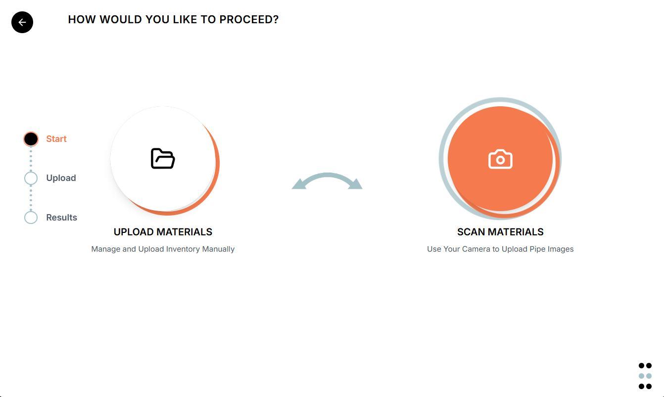
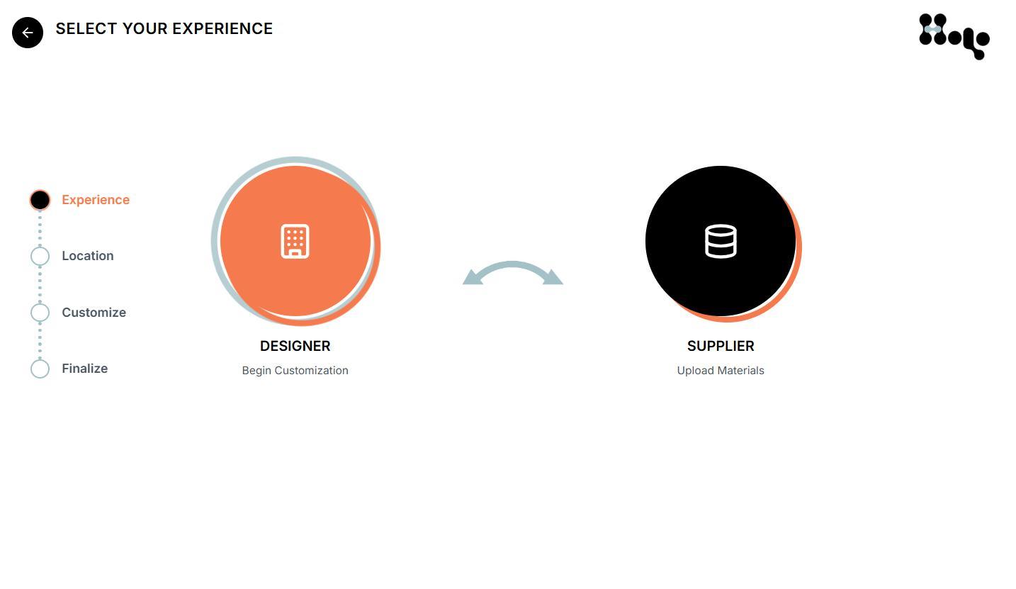
TWO ENTRY PATHS
Users have the option to enter as a or ausing each different path for different uses. with this route. and track available stock for designing with. designer supplier Designers can engage and create unique structures Suppliers can upload materials
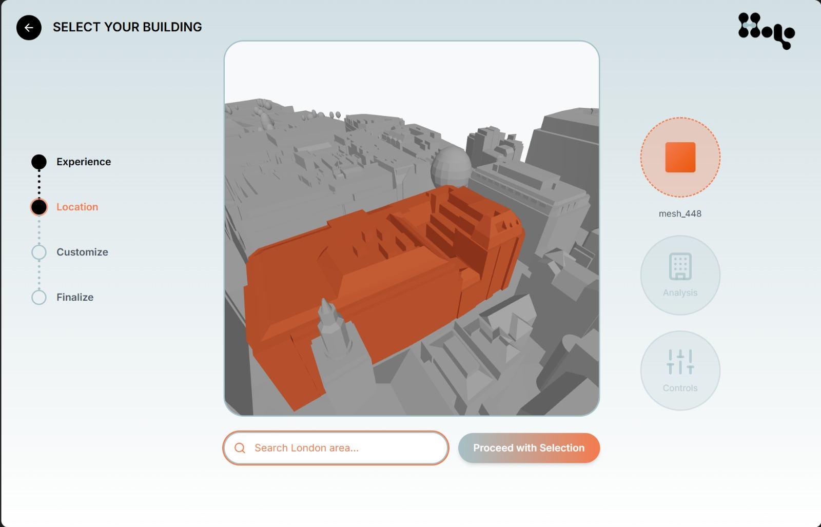
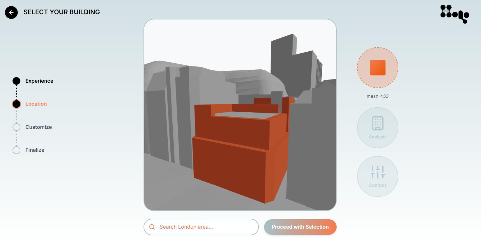
DESIGNER ROUTE
LOCATION SELECTION TO BEGIN DESIGNING
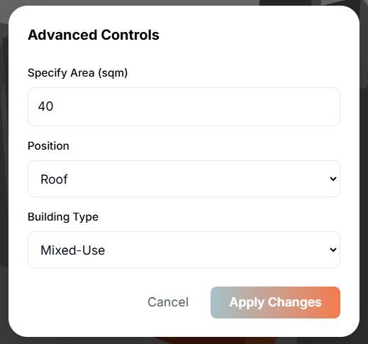
VIEW ANALYSIS AND ACCESS OTHER CONTROLS
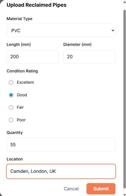
SUPPLIER ROUTE
Suppliers can upload material data manually or use the scanning tool , specifying type, dimensions, quantity, condition, and location for automated identification and quality assessment. This dual input system streamlines onboarding, increases material traceability, fostering a transparent and efficient reuse network.
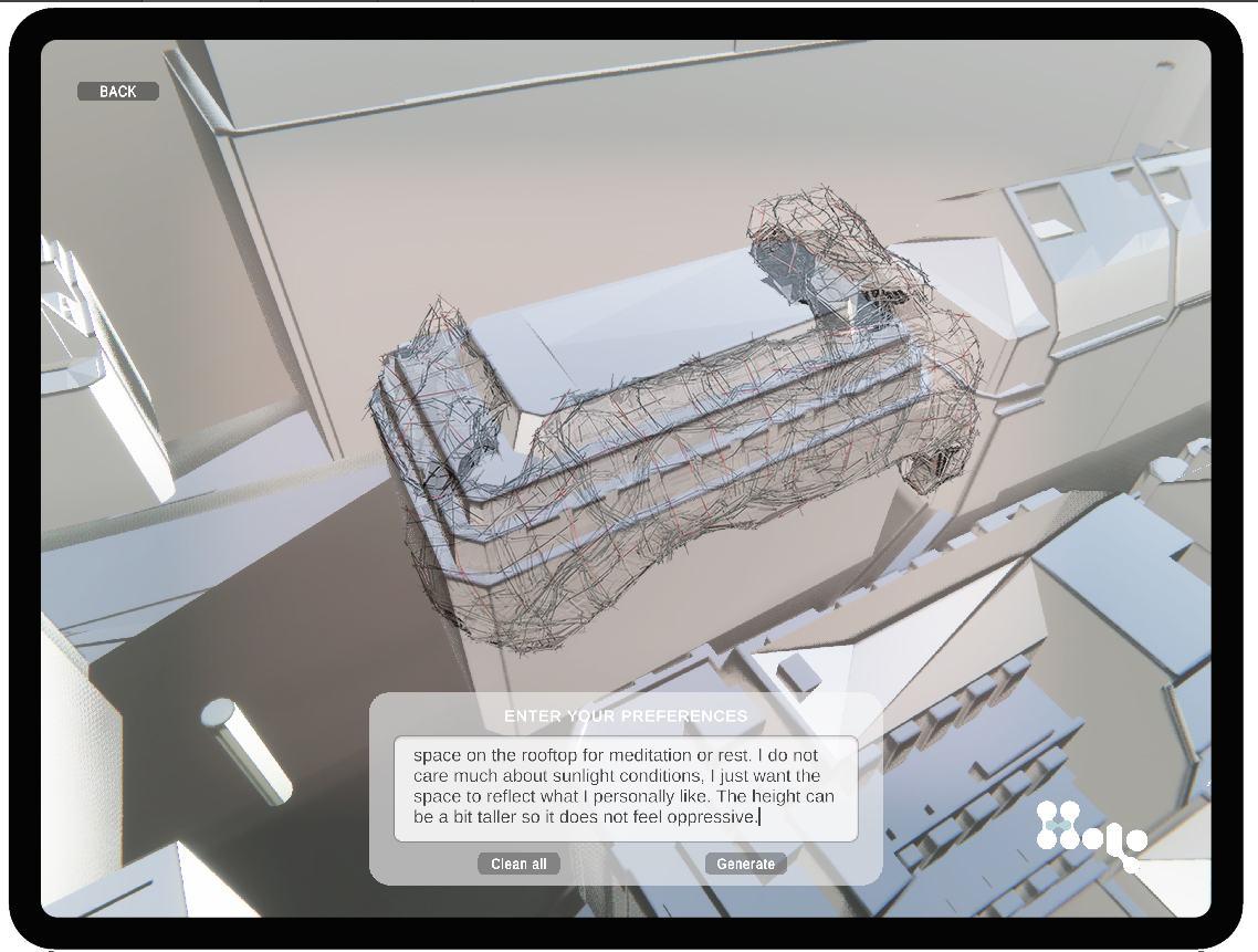
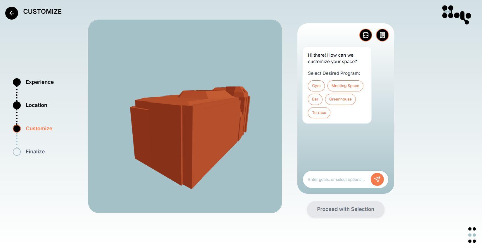
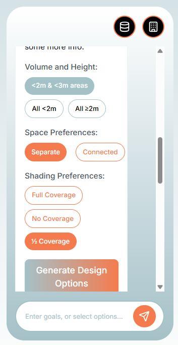
USER CUSTOMIZATION
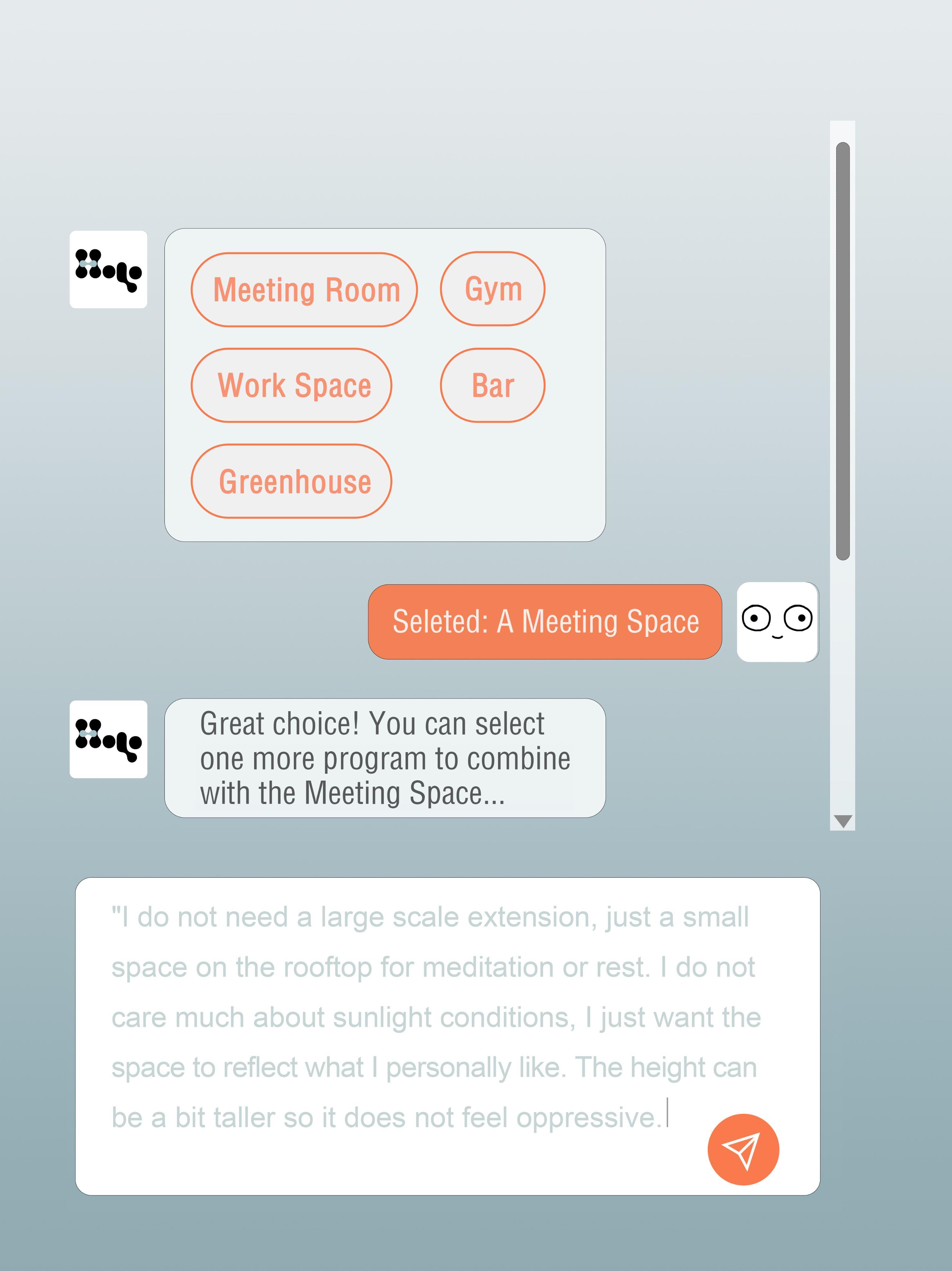
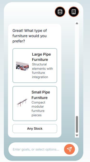
The user can have a natural language conversation with the chat, which is aided in the back end with machine learning models. By selecting different programs, furniture types, and asking other natural requests, which are processed using an LLM in the back-end.
AI CHATBOT TO RELAY USER DESIRES TO BACKEND STRUCTURE CREATION
USER CAN SELECT PROGRAM,
COVERAGE, AND HEIGHTS
USER CAN SELECT DESIRED FURNITURE PLUG-INS
USER
CUSTOMIZATION
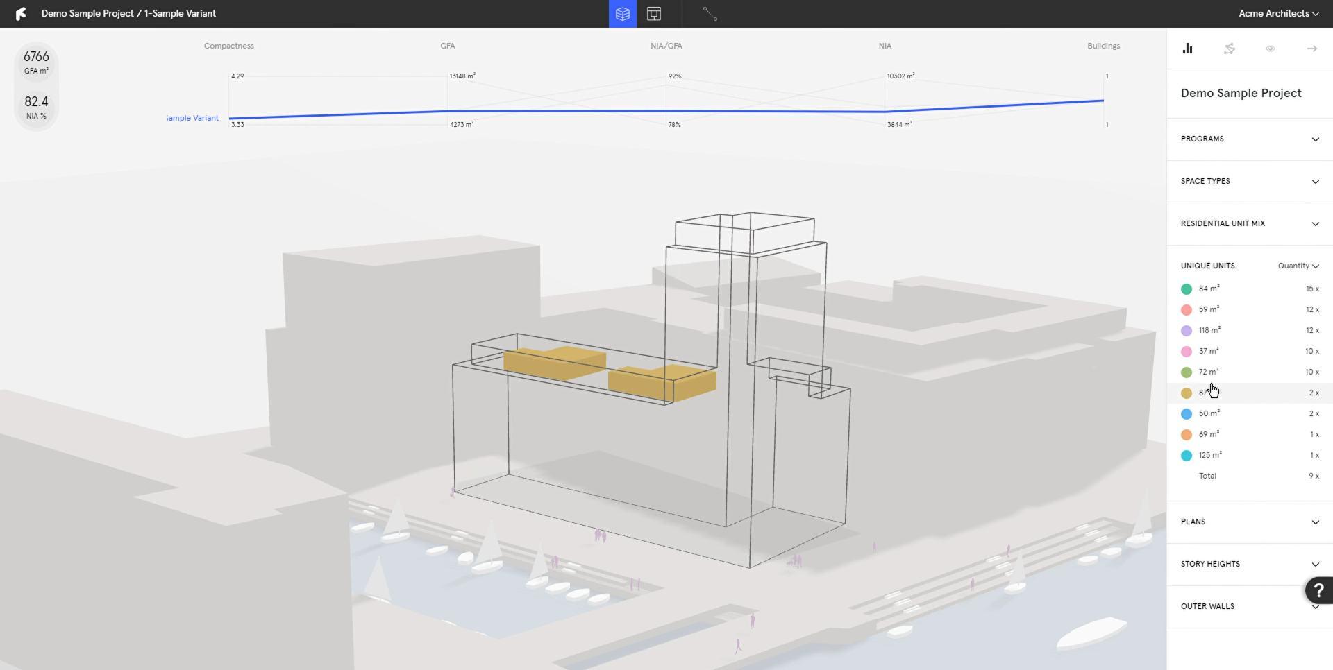
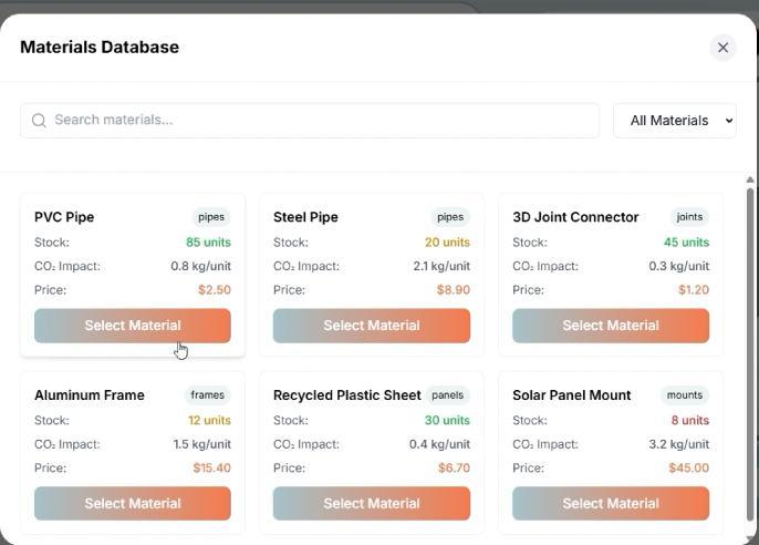
Users can browse a materials database displaying stock availability, CO₂ impact, and pricing. while tailoring structures to their functional and aesthetic needs. By integrating environmental and cost metrics into the selection process, the platform empowers users to make informed, sustainable design decisions
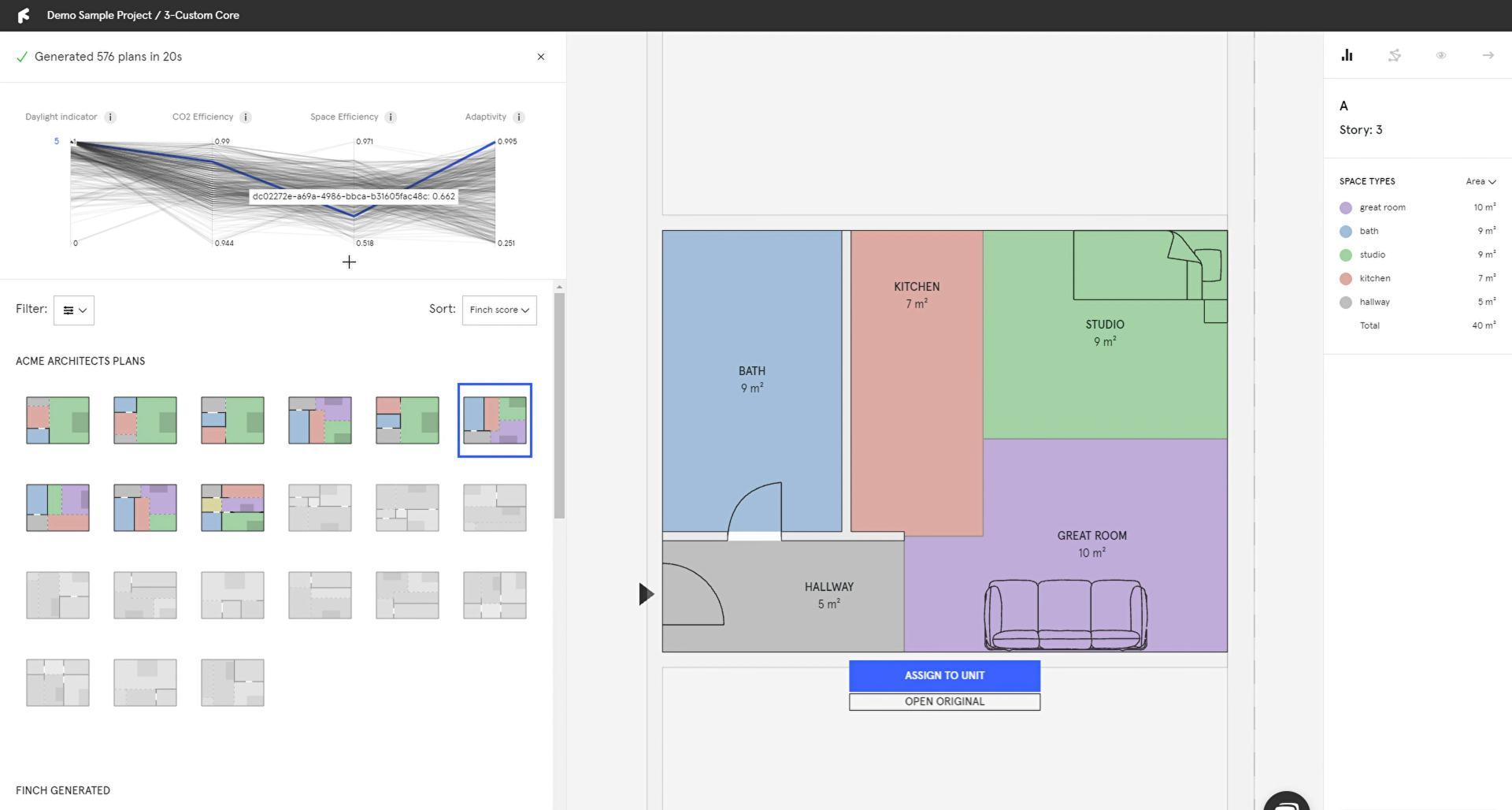
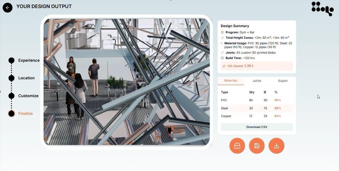
DESIGN RESULTS
Hololab’s design output interface, where users can review their finalized structure, complete with a visual rendering and detailed material breakdown
. The platform provides key statistics, such as the quantities and types of materials, joint counts, build time, and CO₂ savings.
Users can download high-resolution renderings as JPG files, export material data in CSV format, and access an immersive VR view to experience the design at scale.
This integrated output ensures both visual and technical clarity, supporting fabrication, assembly, and communication of the design.
RENDERINGS + OVERVIEW
RENDERINGS
SYSTEM OVERVIEW
PROFILE VIEW
STREET VIEW
AERIAL VIEW
INTERIOR VIEW
INTERIOR VIEW
BUILT SYSTEM
Modular Pipe Frameworks:
Assembled from reclaimed construction pipes of varying materials (metal, plastic, composites)
3D-Printed Custom Joints:
Physical joints connect irregular or standard pipe geometries, accommodating flexible assembly
Recycled Fabric Skins:
Lightweight, water-resistant skins made from recycled materials (e.g., parachute nylon)
stretch over frameworks
Furniture Plug-Ins:
Additional functional elements like benches, tables, and gym equipment constructed solely from reused pipe components
DIGITAL PLATFORM
Material Driven Design System:
Starts with real time databases of reclaimed materials with background data available
Unique Site Recommendations:
Uses environmental data, building geometry, and user input to generate optimized designs
Automated Aggregation + Joint Design:
Generates modular frameworks by suggesting aggregation patterns (based on available material dimensions) and designs custom joints
User Customization:
Users can adjust priorities (privacy, shading, greenery, volume) and see updated structure options
Output Files:
Export ready 3D files, material lists, assembly diagrams, and reports
MANUFACTURING + PHYSICAL MODEL
3D PRINTING
PHYSICAL MODEL
MANUFACTURING PROCESS
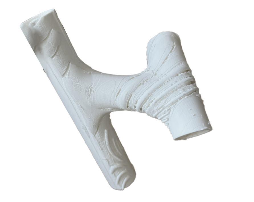
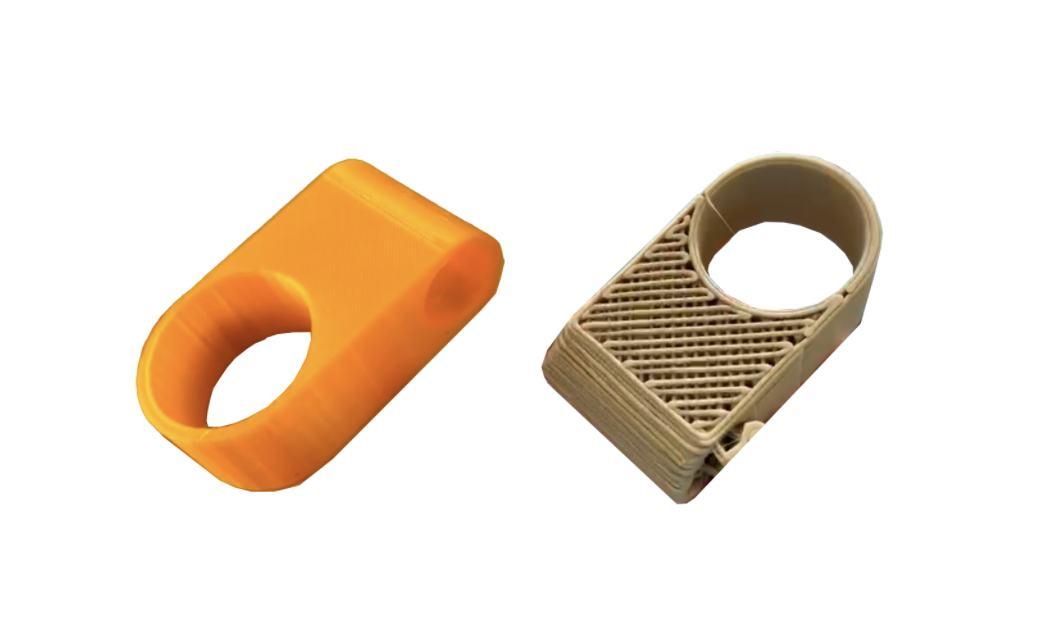
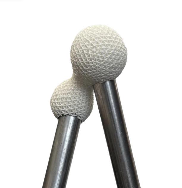
Prototyping many types and shapes of joints allowed us to grasp different issues with manufacturing 3D prints. Early prototypes struggled with excessive print times and inconsistent quality, especially when designs included fine details or unsupported overhangs.
Larger scale prints introduced challenges to avoid warping and maintain high resolution. Overly intricate geometries often led to failed prints due to lack of structural support during fabrication as well as difficulty removing supports that held the detailed textures.
These results prompted a shift toward more print-friendly designs, balancing form and functionality. By testing and adjusting parameters, HoloLab developed a set of joint typologies that are geometrically versatile and fabrication friendly, with meaningful texture.
JOINT PROTOTYPING
This phase of the HoloLab project . A wide variety of joint geometries were tested using PLA 3D printing to evaluate structural behavior, print resolution, and the feasibility of applying surface texturing directly to printed joints.
Early prototypes revealed challenges such as inconsistent layer quality, long print times, and failure due to unsupported overhangs and issues especially evident in complex or finely detailed parts.
We adjusted form complexity and printing parameters to develop robust joints that were not only structurally sound but also fabricationfriendly, while maintaining our meaningful application of texture across the pieces. To achieve high-resolution output, we refined our mesh optimization strategies and evolved our designs to accommodate limitations of the printing process. focused on developing joint typologies through extensive physical prototyping, exploring the interplay between digital design and fabrication constraints
JOINT PRINTING EVOLUTION
A collection of successful and unsuccessful attempts as we navigated from standardized joints to customized organic wrapping joints. Using different filament, nozzle size, and resolution.
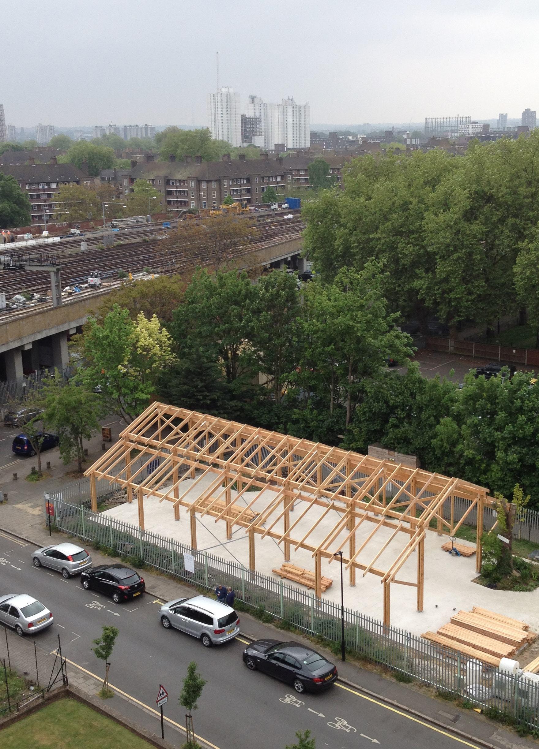
PHYSICAL BUILT MODEL
Refer to appendix pg. 123-124 for more content.
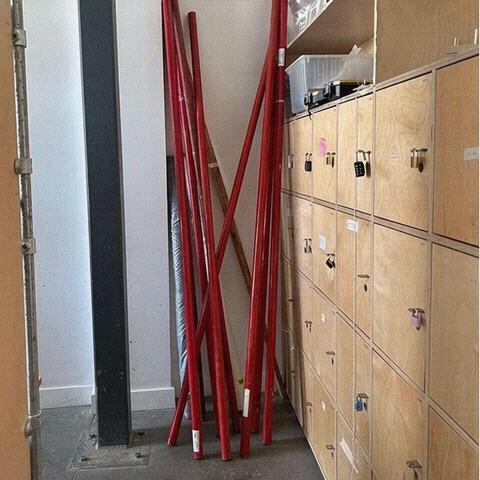
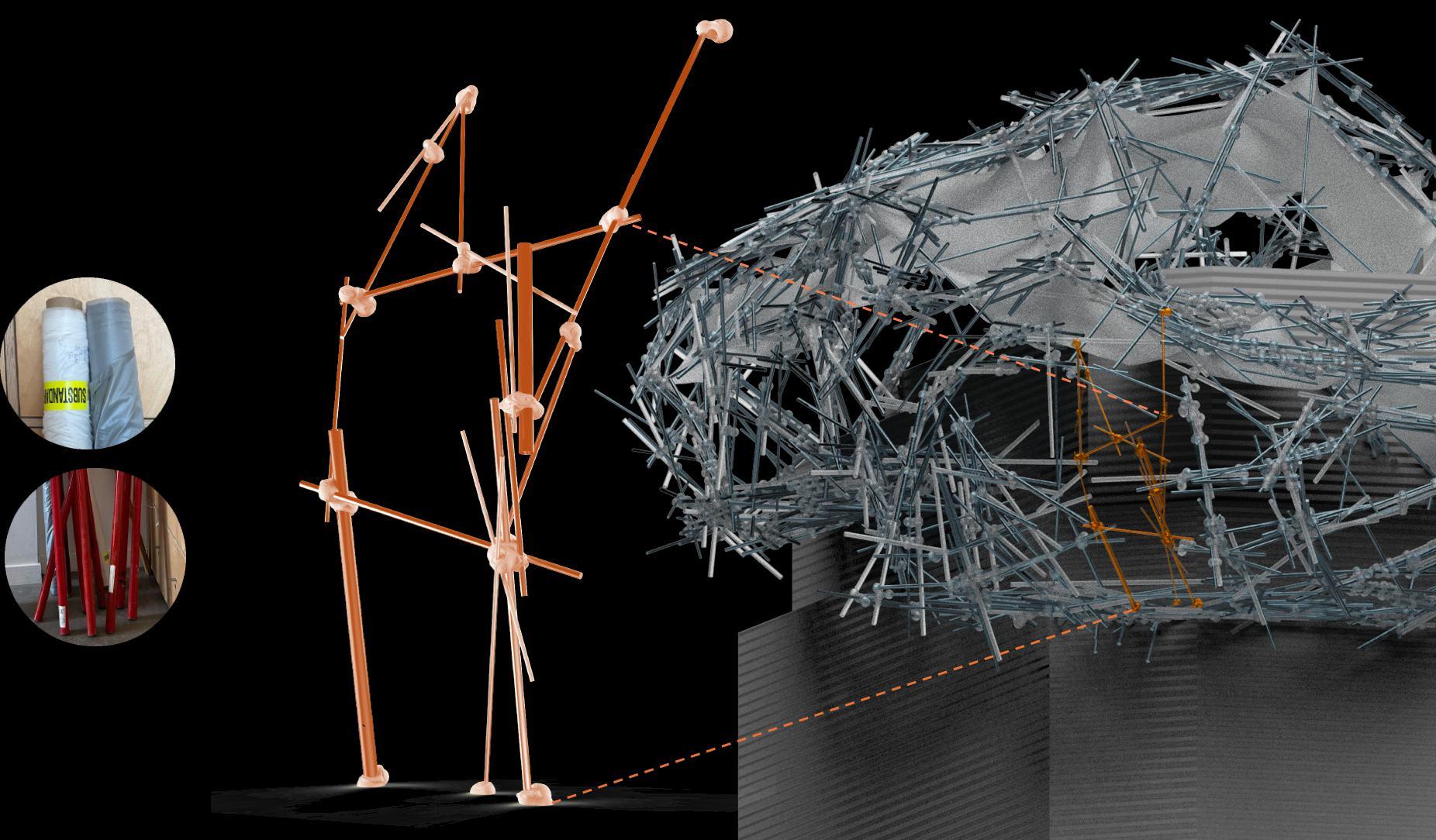
RECYCLED AND DONATED MATERIALS
Our main contributors for this work were Material Index UK and Heathcoat UK
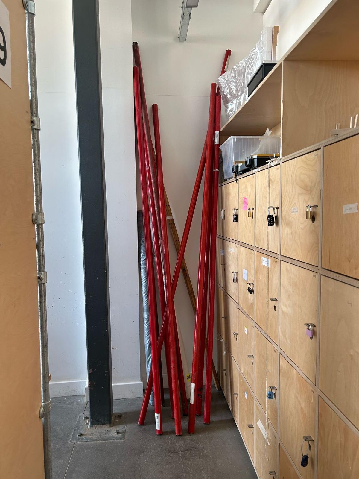
MATERIAL INDEX - PIPE REUSE
AUDITING PLATFORM - CONNECTING VIABLE DEMOLITION MATERIALS TO USERS. Connecting us to demolition materials from GSK House in west london.
Demolition audit
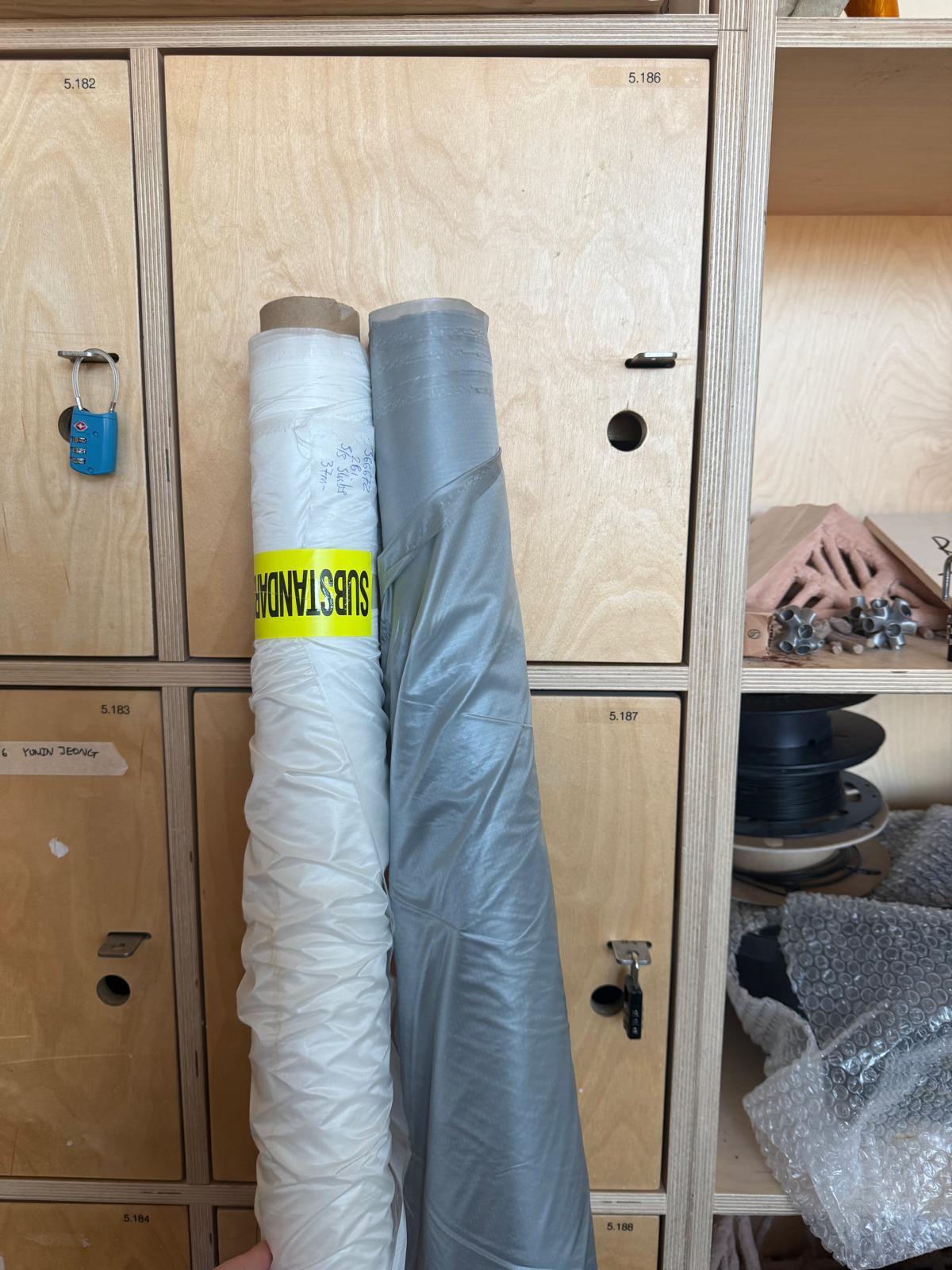
PARACHUTE MATERIAL REUSE - HEATHCOAT UK
Military grade nylon production company. Donated two bolsters of fabric with production quality errors, sitting as waste at their factory,
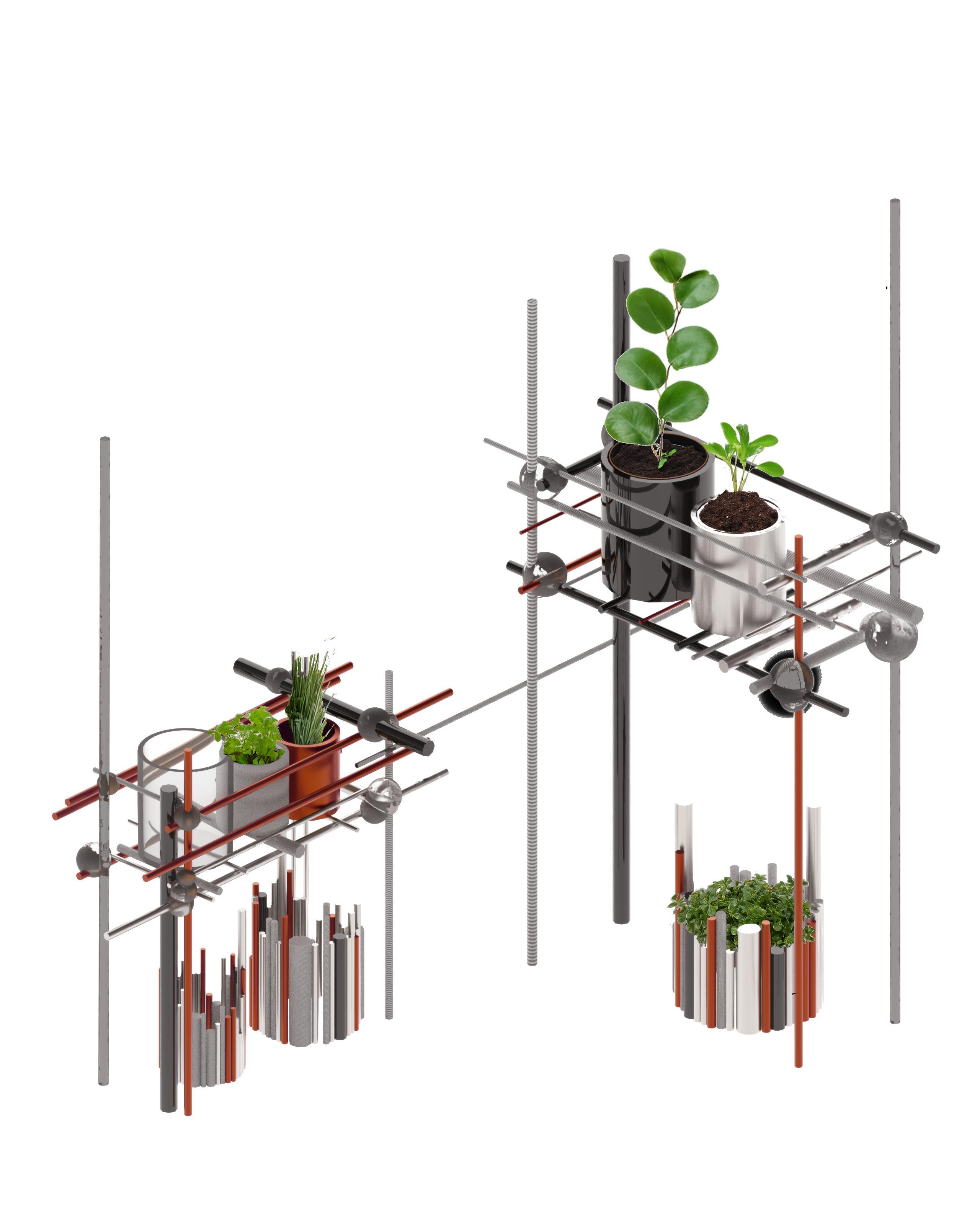
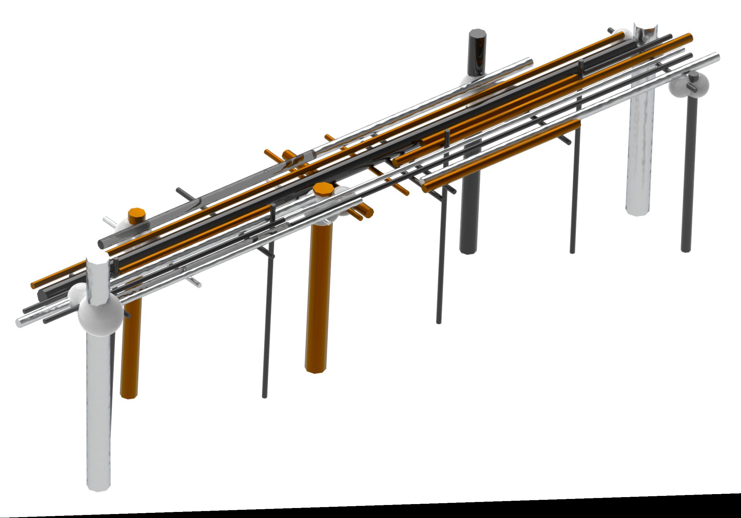
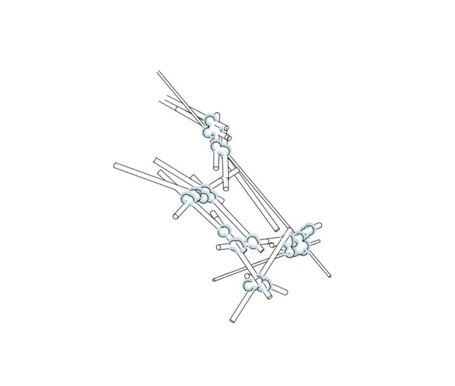
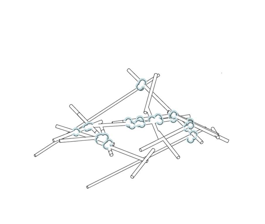
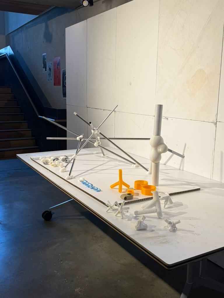
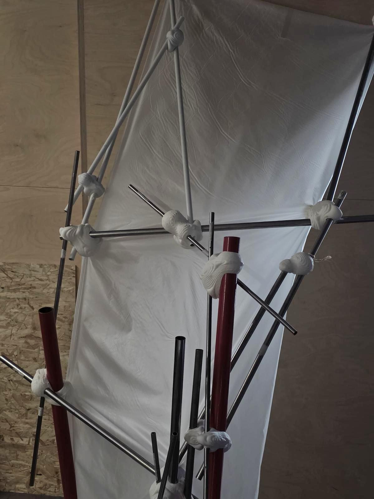
PHYSICAL MODEL ONE
This physical model represents . The assembly serves as an early exploration into the integration of customized 3D-printed joints with readily available materials, demonstrating how computationally generated connectors can adapt to varied pipe diameters and orientations.
a tangible prototype in the project’s development, constructed using a combination of found pipes and additional components generously donated by Material Index London
This is one prefabricated section from a larger structure.
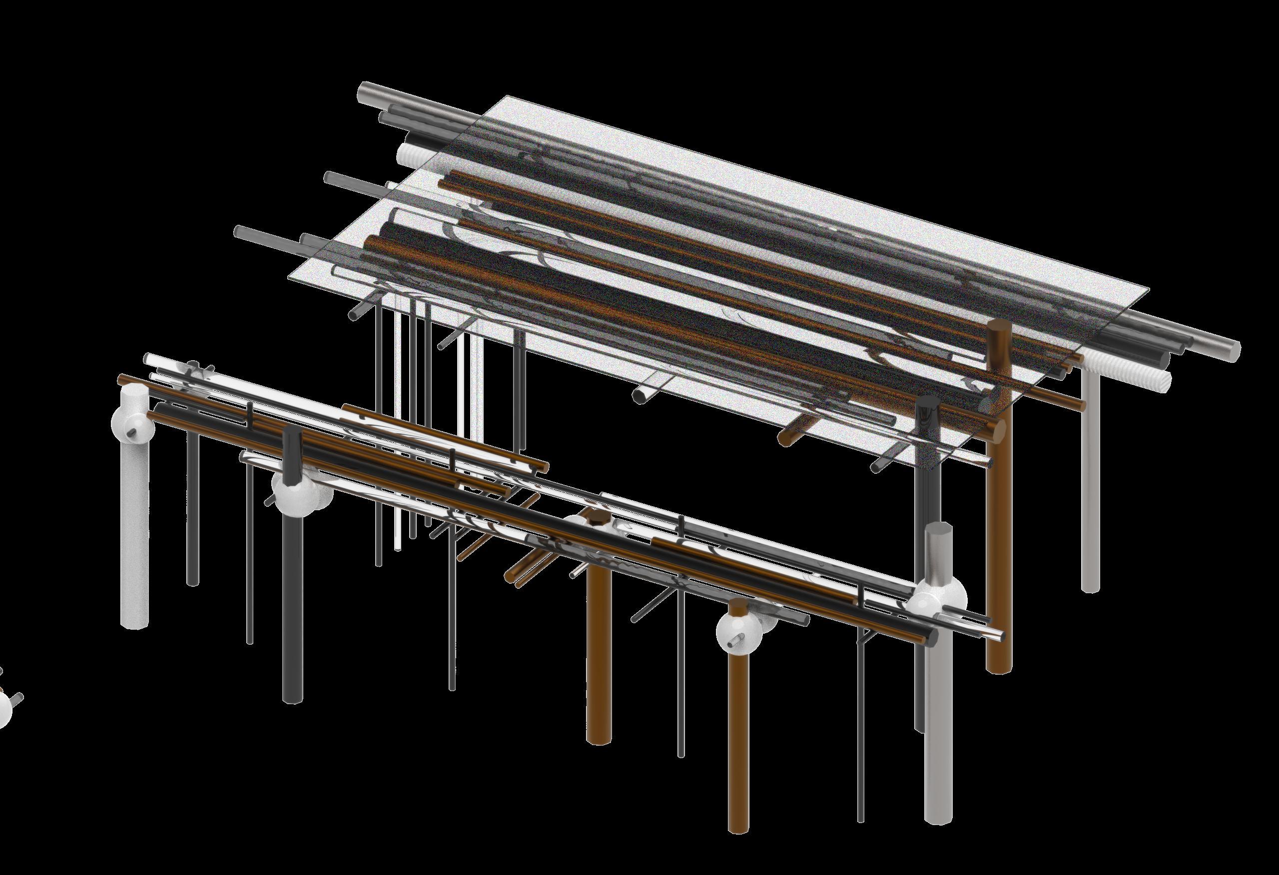
PHYSICAL MODEL TWO
The second physical model, designed for the BPRO Show began by selecting stable reclaimed pipes to serve as the vertical base elements.
Insert each pipe into the custom 3D-printed joints, ensuring the base joints rest flat on the ground for stability. Attach shorter horizontal or diagonal pipes into the base joints, locking them with angled connectors
. This creates the initial frame triangle or square, giving the structure its first measure of rigidity. Continue adding layers of pipes and joints in an iterative process, testing balance and structural capacity as you go.
This prototype pavilion demonstrates Hololab’s approach to sustainable and adaptive design through the reuse of reclaimed materials. the structure is held together by custom 3D-printed joints designed to accommodate irregular dimensions and maximize material viability.
Built from donated pipes and surplus parachute fabric, Designed for the BPRO Autumn Show. blurs the line between digital precision and improvised construction,
The result is a lightweight, expressive assembly that showcasing how computational design and circular material strategies can generate new architectural possibilities.
APPENDIX
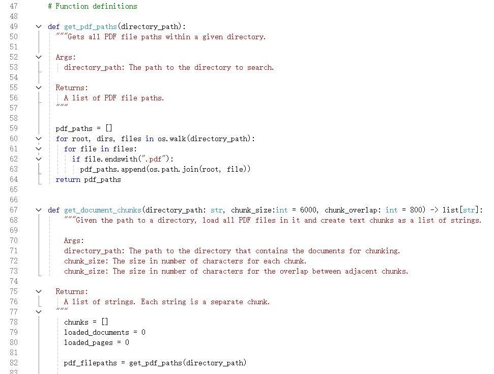
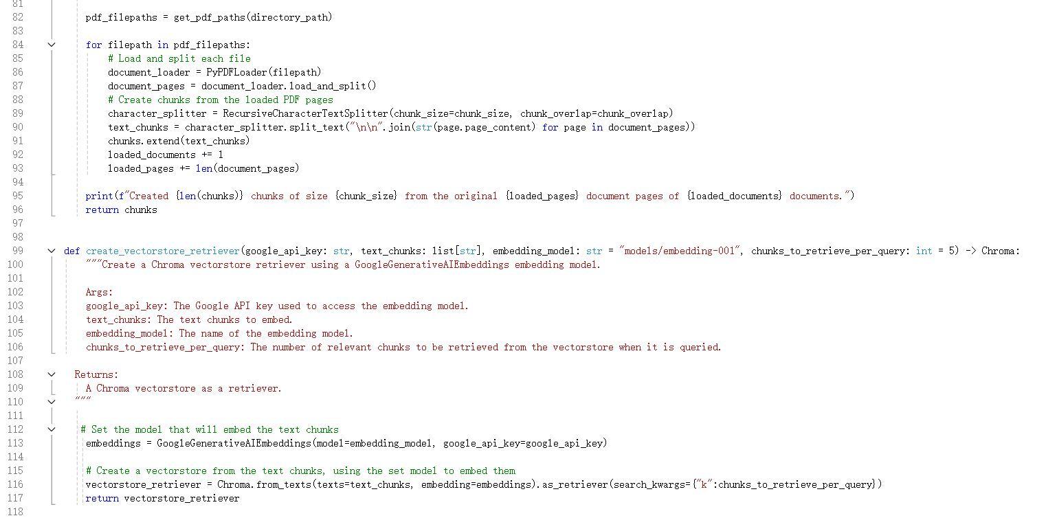
SCRIPTS
REFERENCES
APPENDIX 01 03 02
PREVIOUS ITERTATIONS
CODE SCRIPTS
VORONOI
RHOMBIC DODECAHEDRON
RHOMBIC DODECAHEDRON
CUBIC EXPLORATION
MESH FACES
TRIANGULAR EXPLORATION
MESH FACES HEXAGONAL PRISM
PIPE METHOD STUDIES
PIPES PLACING
EDGES
EDGES
LINES CONTOURS
DIFFERENT PIPE AGGREGATIONS PROCESSES PER AREA
JOINT EVOLUTION
JOINT EVOLUTION
FURNITURE ITERATION ONE
FURNITURE + SPACE ITERATIONS
SKIN DESIGN EVOLUTION
SKIN ATTACHMENT EVOLUTION
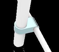
These connectors are designed to attach flat, recycled materials like parachute nylon sheets to the structural pipe framework. They create clean, tensioned surfaces that act as protective skins or shading layers.
ATTACHING SHEET MATERIAL
RIBBON-LIKE MATERIAL
For more dynamic or sculptural applications, HoloLab employs connectors that support woven or ribbon-like materials. These systems embrace curvature and movement, enabling the creation of textured, breathable facades.
DIAGRAMMING
This page presents the
The wireframes outline a streamlined experience beginning with user login, project creation, and design intent selection. first iteration of the HoloLab platform's user interface, developed in Figma to explore user flows and interaction design.
Subsequent screens allow users to input site details, adjust spatial parameters (like coverage, solar penetration, and volume), and receive intelligent region suggestions for potential structural insertions.
FIGMA UI ITERATION TWO
This second iteration of the HoloLab platform interface
builds upon the initial flow by introducing two distinct user paths: Designer and Supplier.
After login, users are directed to choose their experience. Designers are guided through site selection using an interactive urban map interface to locate and define the target building.
Suppliers, on the other hand, access a structured material database to upload or browse available components—such as copper, HDPE, and PVC pipes—each tagged with size, material type, and source information. This iteration prioritizes a more polished UI.
FIGMA UI ITERATION TWO
PHYSICAL MODEL VERSIONS
PHYSICAL MODEL OPTIONS
PREVIOUS ITERTATIONS
HUNGARIAN ALGORITHM
WIND ANALYSIS
VIEW ANALYSIS
USER LOCATION PREFERENCES
HEATMAP REMESH
MESH MANIPULATION
STRESSLINES
JOINTS GENERATION
SKIN GENERATION
ASSEMBLY PROCESS
PREVIOUS ITERTATIONS CODE SCRIPTS APPENDIX
WEIGHTED COSINE SIMILARITY WITH TARGET PERCENTAGES