
DANCE AND PERFORMANCE COLLEGE IN NEWCASTLE (THIRD YEAR PROJECT)
RE [CHARGING] COMMUNITY HEALTH HUB (FIFTH YEAR PROJECT, SEMESTER TWO)
WORK IN PRACTICE (YEAR OUT)
CONTENTS
THESIS: TRANSFORMABLE ARCHITECTURE (FINAL YEAR PROJECT) 20222020201920182021
SUBURBAN FAMILY HOUSING AND RETROFITTING PROJECT (FIFTH YEAR PROJECT, SEMESTER ONE)
river
North
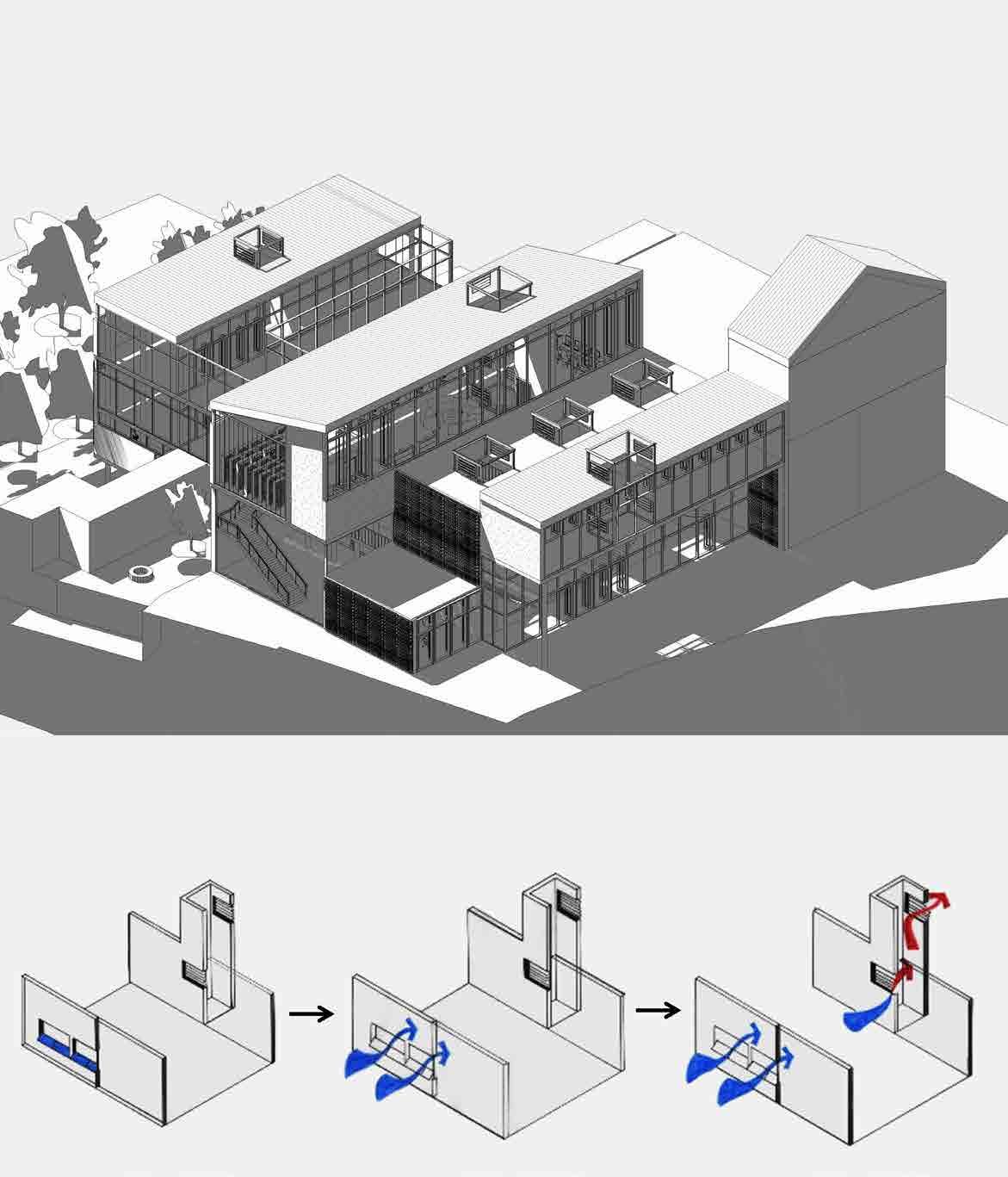
2 DANCE AND PERFORMANCE COLLEGE IN NEWCASTLE THIRD YEAR THESIS PROJECT, SEMESTER TWO, INDIVIDUAL WORK Exterior Render of Dance and Performance College with Plans KEY 0. Solar Chimneys for ventilation; 1. Indoor performance area; 2. Reception and waiting area; 3. Meeting room; 4. Café ground floor and first floor with balcony looking down to performance area; 5. Office; 6. Existing Roman Wall; 7. Private Entrance for office; 8. Outdoor Performance area; 9. Bridge with folded façade main connection; 10. Dance Studios; 11. Library; 12. Resource Room; 13. Bridge above performance area; 14. Classrooms; DESIGN DRIVE To create a college and choose what activities and studies will be taking place where my project is an institute for dance and performance. have created a place where students can do what they love, practice dance, learn about music and have live performances in front of an audience of family and friends.The college is separated into 3 main parts: •PUBLIC – café; library; resource; classrooms •PRIVATE – Office; Dance Studios •HEART of the building – Indoor and Outdoor performance area

The college circulation is formed by bridges which designed in reference to the seven bridges in Newcastle but also inspired by the dance and the constant movement in it. The main bridge above the roman wall serves as a connection between the two parts of the college as well as a threshold between the public-private and rehearsalperformance. decided to build above the roman wall instead of demolishing it because find the ancient remains beautiful and coming via the dance studios or café occupants can stand on the bridge and examine it from above then think about the past. In this way, the college connects with the past and ancient as well as the present moment and future. For the skin of the dance college, am using Polycarbonate and Glass so light can penetrate through the façade and make the spaces naturally lit. decided to use polycarbonate sheets because I wanted visitors to be drawn into the building in a desire to see what is happening inside and what type of performance is on. Polycarbonate gives the advantage to reveal things but not completely.
located
Side Render of Dance and Performance College


The site is next to Castle Garth to the and Tyne to the South. order get the there that lead situated East from the site. The site wasoriginally a car park and green area with remains of the Roman wall. The site slopes toward the river. Newcastle is an industrial city but has its history, landmarks and monuments. The landmarks of Newcastle include some of England’s most famous and impressive. There are many historical ruins in Newcastle Area for example the roman wall, Castle Garth and the Black Gate.
river
During the nighttime, the polycarbonate sheets become colourful and the façade starts to glow.
to
down to
you down. They are
External Render of Bridge above Roman Wall

3D Exploded Floor PlansInitial Sketches Exploring Form

Polycarbonate Dance Studios
is stairs
In
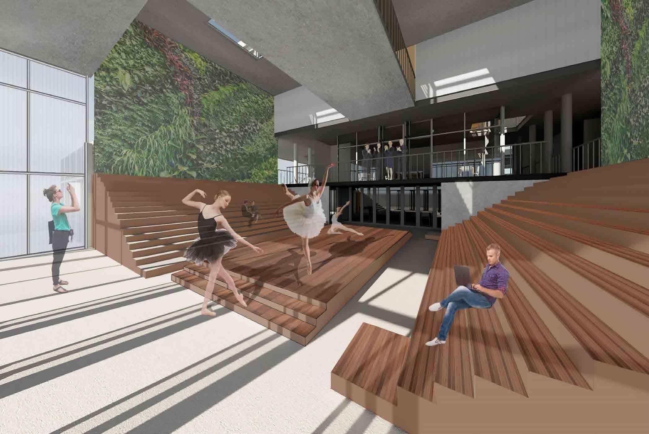
Imagining the Cafe Balcony when there is a live show
Interior Render of Library

Dance College Stack Ventilation through Solar Chimneys

In my design, used natural ventilation because wanted to achieve the maximum human comforts for occupants. incorporated glass shafts through the whole building which plays the role of a chimney and stack ventilate the whole building. In order to have good airflow, placed windows at the opposite sides as well each block of the college is at a different height so it can catch the prevailing wind without being blocked. The chimney has ventilation shafts from where the hot air escapes. Another use of these chimneys is that used glass so they can act as a light well and roof lights. They help light to penetrate deeper into each space.
Sustainability is one of the core objectives of the College therefore few strategies have been incorporated such as natural ventilation, rainwater harvesting, solar panels, passive cooling and heating strategies green walls and roofs as well as outdoor green spaces. The library is located on the second floor and has North facing windows which provide lighting that is consistent during the day without causing glare. The windows to the South are clerestory windows above eye level, their job is to deliver light deeper into the college. In cooperation, the windows to the North and South open help with natural stack ventilation which is achieved by the glass shaft. Inside the interior is from sustainably sourced softwood which is a natural material and creates a pleasing ambience. The classrooms on the second floor create a cantilever which is supported by two steel columns. In bad weather, it acts as an overhang and shelter for people to hide from the rain.
Form Finding MDF Model Scale 1:200


Cutting through the North Façade you can see the indoor performance area, the café ground floor which opens toward the performance and the first floor where people stand on a balcony watching the performances. The café and indoor performance area link together as one when there is a live show. Standing on the balcony provides the same experience for the audience as standing on the tribunes. The cafe is an important link between the performance area and other parts of the college. The café is supported by steel columns with small balconies looking towards the performance area. It has bifolding doors which open when there is a live performance allowing occupants to have a drink and still see the show. Even if occupants use the café on the first floor there is a balcony they could stay on and look at the performance from above. Green internal walls improve air quality and create a pleasant ambience. Dance Studios occupy the First and Second Floors on the South Façade. I am using glass and Polycarbonate sheets which have different colours during nighttime. In the corners, the folded façade is visible which creates places for dancers to sit and stretch. My inspiration for the folded bridge comes from the bridge at the Royal Ballet that rotates in sequence. The complex structure serves as a threshold for the dancers to get into the studio. My initial ideas started to form during my experimenting with paper folding. I began folding it in different ways and getting 3D shapes. There is a second main bridge which goes directly above the stage between the library and classrooms. The void between the ground floor and first floor helps the ventilation, allows light to penetrate several floors and most importantly helps to connect two–way communication between occupants located on different floors.
Interior Render of Indoor Performance Area (heart of the building) and Cafe


Cross Section showing Solar Chimney Scale 1:50
In terms of materiality the college is constructed of concrete floors, walls and roofs with steel columns supporting the dance studios and cantilever which is the classrooms. Concrete has high storage capacity with moderate thermal conductivity therefore it absorb the unwanted heat during the day and then release it at night and helps with ventilation. have exposed concrete ceiling and floors which will absorb, store, and later release significant amounts of heat during the night and will contribute for winter passive solar gain. For the steel columns am using concrete foundations which can help reducing thermal bridging.For the interior finishes and performance area am using timber because it has low embodied energy and it reduces the CO2 travel consumptions. Timber offers aesthetical advantages because of it is natural material and has warm texture. For the dance studios the materials are using concrete, glass and polycarbonate sheeting. Polycarbonate has been chosen instead of glass because it is transparent but doesn’t revel everything, moreover it is durable and can resist high and low temperatures and it is lightweight.
3
Interior Render of Folded Bridge above Roman Wall
Environmental Section North South Scale 1:200

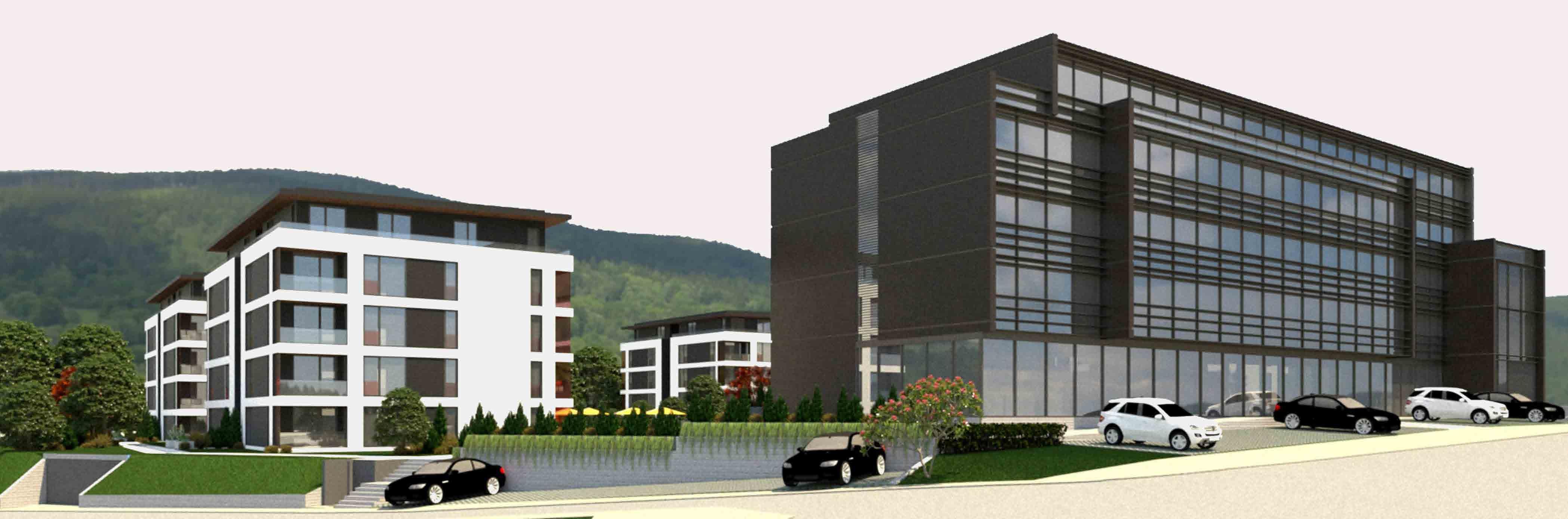
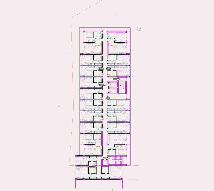
BASEMENT PLAN – We have designed a kitchen which serves the ground floor café and restaurant, a big conference room and a garage. GROUND FLOOR PLAN – We have designed a smaller conference room, outdoor seating and indoor café/restaurant FIRST FLOOR PLAN – We have designed twin hotel rooms with bathrooms. To the North and South, there are overall four apartments for sale as the client required, it is a one bedroom apartment with a view. The hotel has four floors where the second floor, third floor and fourth floor are the same as the first floor layout. The render below shows the hotel’s front facade looking towards the street.

was working on this project during my second placement in a company called VESTA Design. The design drive was to create a closed complex which consists of four residential buildings, the courtyard in the middle and a hotel for guests. Since started in April I have been part of the team which worked mainly on the hotel was involved in the creation of the floor plans using AutoCAD software. In addition to that, I was responsible for the positioning of furniture and internal layout rendering. As you can see below have shown the AutoCAD basement plan, ground floor plan and first floor plan.


Later on, when the client was please with the configuration and design of the Hotel everything was checked by the senior architect. Afterwards, used Photoshop to edit and render the proposed plans. As you can see below have shown the rendered basement plan, rendered ground floor plan and rendered first floor plan. The project now is in the final stage as we started to create exterior renders and thinking about the main façade and material considerations. The render below shows the hotel and residential buildings which enclose an interior courtyard. The existing site was a public pool area, therefore we decided to keep the existing feature.
Exterior Render of inner courtyard with ‘‘Raffy’’ Pool
4
Basement Floor Plan (Rendered)
YEAR OUT, WORK IN PRACTICE
First Floor PlanGround Floor PlanBasement Floor Plan
“RAFFY” COMPLEX
First Floor Plan (Rendered)

Ground Floor Plan (Rendered)

PROJECT DESCRIPTION
Exterior Render of ‘‘Raffy’’ Complex
Nighttime Render of Open Plan Living room
Proposed Plans and Elevations

Daytime
Daytime Render of Open Plan Living room Render of Kitchen and


REAR EXTENSION AND OTHER WORKS IN PRACTICE
PROJECT DESCRIPTION
Island
Existing 3D Rear View Existing Elevations Existing Ground Floor Plan Proposed 3D Rear View Proposed Elevations Proposed Ground Floor Plan


This is a project I worked on by myself using Revit software. It was completed in two days and checked by the architect. The client was pleased with the design and now it is submitted to the council. This is a rear extension designed for a client in Tiddington. The conservatory at the rear has been demolished and replaced with this extension. It is an open plan kitchen/diner/lounge with large side windows alongside, bi-folding doors and roof lights which bring plenty of light into the space making it naturally lit. I have also created exterior and interior renders showing the ambience with artifi cial lighting and without.


5
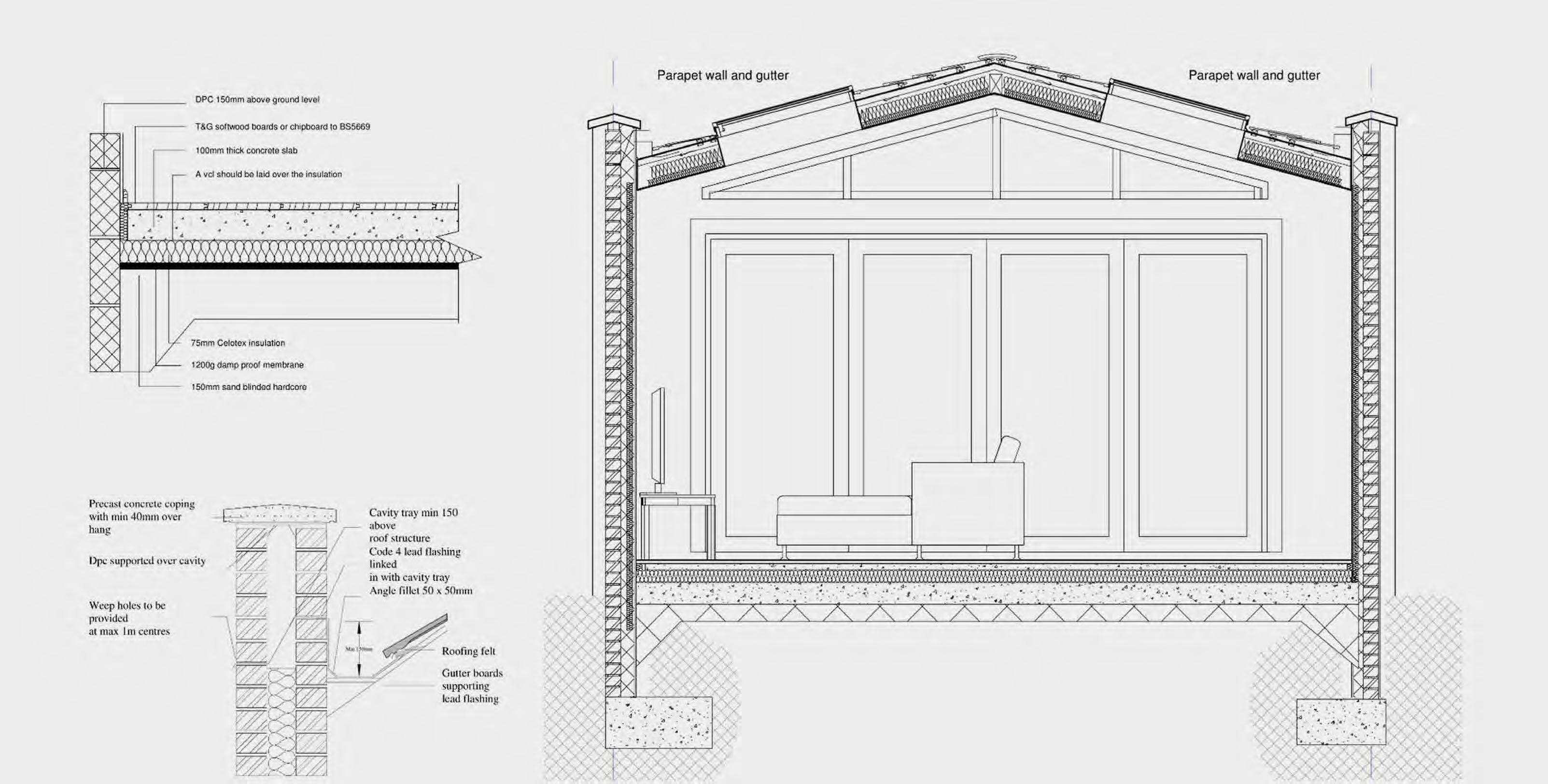
Parapet Detail with Box Gutter
Solid Ground Floor Detail
Exterior Proposed Rear Render
The second project to the right also developed by myself with the supervision of the architect. The client wanted a single-story rear and two-story extension, making use of natural lighting features and a domed window in the ceiling. The new space has a fresh feel with natural feel lighting features for a comfortable environment any time of the day. My additional job was to create external and in ternal renders for the client, as well as the proposed interior layout of the kitchen. On the two renders, natural and artificia light was tested as well as the layout of the kitchen. This project was used for the official website of the company.
Exterior Proposed Rear Render
Construction Cross Section of Rear Extension

YEAR OUT, WORK
Daytime Kitchen Render Nighttime Kitchen Render


Construction Detailing of New Built Houses
SUBURBAN FAMILY HOUSING AND RETROFITTING PROJECT

Project
FIFTH YEAR PROJECT, SEMESTER ONE, GROUP PROJECT (TEAM OF THREE)
PROJECT BRIEF:
The project area is on 13.600 square meter. There are 21 houses and 1 Energy Centre located in the proposal. On the west side of our site, there is an existing walking path covered with tall trees which connects Debdale and King George V Parks. Therefore the proposal is designed accordingly to the trees.
Project Site for New Build and Retrofit
While trying to achieve this we decided to create communities which will give residents a chance to socialize with other households in COVID-19 situations and by creating a community we are fairly reducing the cost for heating systems by connecting each house to an energy center.
For the design of houses, we tried to use open plan and also used modular systems to reduce the cost.


Our key principle is designing a sustainable passive house for a family of 4 with 2 working parents.


3D Construction Section

We aligned our buildings to north-south axis to get the direct sunlight and use it for both solar panels and passive heating of the house. For unwanted situations like for hot summer days, rain, increased humidity, all the houses are equipped with automated solar shades and operable automated roof windows. The roof windows are also used to get sunlight in the corridors and in the bathrooms. For passive ventilation and cooling, the house is equipped with windows on all sides. One can open windows on different sides for a soft breeze. With the Smart Home Control panel, the house will always controlled for optimum comfort levels. From the elevations, the materials of the façade can be seen. Wood panels are used for the first floor which correspond to structure material CLT and convey a nature feeling. Bricks are installed at ground floor which is coherent with the surrounding buildings. On the mono-pitched roof, solar panels are used to gain solar energy and generate electricity, which contribute to decrease energy cost. To prevent overheat and over exposed to sunlight, adjustable shutters are widely utilized to cover windows, and vary by smart home system according to changing temperature, weather, and light conditions. We used 45 cm walls for dividing public and private parts of the project site. A brick wall to correspond to the surrounding texture and wooden planks applied on top of the wall for using it as a bench.
The project goal is to design a prototype for new built and then apply it to existing neighborhood and retrofitting it.
Passive and Smart Home System Diagrams
We chose Manchester which a major city in the northwest of England with a rich industrial heritage.
New Built Project Development Site Manchester
Site Render of New Built and Retrofitted Neighbourhood


The scheme offers 3 entrances which are connected to the parking lots and direct connection to the walking path on the west side. On the site we propose 20 metre square farming area to each house-hold. In the centre of our site we are putting forward an energy centre for ground source heat pump, treatment systems and distribution of energy.
6
Retrofitting Project Development and Key Principles Design Manuel Brochure for Retrofitting


Site Plan and 3D Site Render of Retrofitted Neighbourhood

We have replaced the smaller traditional windows of the existing home with much larger windows, Velux roof windows and roof lantern. The reason for this was to maximize passive solar gain throughout the day. These types of openings will allow sunlight to pene trate deeper into the building for better lighting and to facilitate the concrete thermal mass. We decided that we wanted to use a concrete slab as a thermal mass for the ground floor as this would store heat through out the day and then slowly release this heat in the evening, allowing the hot air to rise and passively heat the whole house. The reason we have chosen natural ventilation is because we wanted to achieve maximum human comfort indoor. In order to have good natural ventilation we placed openings at the opposite pres sure zones. In order to enhance the natural ventilation so we designed a void between the ground, first floor and loft level to allow air flow to be sustained. The hot air rises and escapes through the Velux roof windows. The windows play a dominant role on the ventilation that is why we choose openings which are mechan ically operated by the people. This provides the oc cupants with control of internal environment. Thermal mass reduces the room temperature during midday and early afternoon and increases the room tempera ture late in the afternoon and early evening hours.
7
Construction Cross Section of North Orientation House Scale 1:50

Creating a green corridor will improve urban ventilation, al lowing the cool air from outside to penetrate into the North Manchester hospital area.

My initial idea for the Village green is to transform it into a sculpture park where individuals who are taking part in the creative therapy can contribute to its development by cre ating customised sculptures. It will also be a public open space for patients, staff and members from the wider com munity. The aim is to re-engage, relax and recharge.

Re [ charging] community hub puts forward the well-being, happiness, and prosperity of the local community of North Manchester. It provides plenty and a variety of activities in which the pub lic can participate and take back control of their lives. The main objective is to bring the region together through exercise, relaxation, creative therapy, and re-charging the body and mind. This program also aims to bring back the connection with nature meanwhile providing support and empowering the ones that need it. The activities are separated into two main groups healthy (BODY) and healthy (MIND). Occupants can choose from a wide range of support that has been worked out carefully for their emotional health and physical well-being.
8 RE [CHARGING] COMMUNITY HEALTH HUB AND A VILLAGE GREEN FIFTH YEAR PROJECT, SEMESTER TWO, INDIVIDUAL WORK Re [charging] Community Health Hub and Green corridor bridging the Sculpture Park and the community of North Manchester
Incorporating a green corridor into my design will pro vide a quicker route for visitors arriving from the West of the site coming from Crumpsall park. It will also serve as a green path connection between the park, the chosen site, and the Village green. It will act as a bridge between the community, the neighbourhood hub, and the hospital.
HOW DOES IT WORK ?
Sculpture parks engage with society by rewarding each visitor with a unique experience. It inspires, challenges and triggers emotions. Sculpture parks are great for walks, ex ercise, time to think and an opportunity to see something new meanwhile enjoying nature.
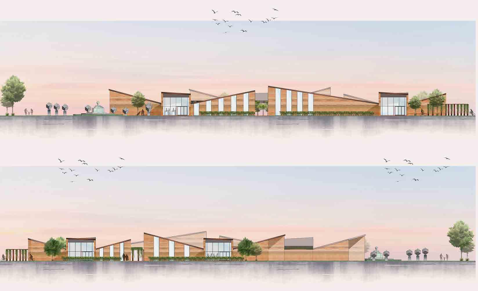
North and South Elevations fully Rendered with Photoshop Scale 1:200
The community of North Manchester experiences some of the highest rates of deprivation in comparison to other parts of Manchester and England where the economy is strong and the population grow ing. North Manchester General Hospital is a key institution in the north part of the city not only because of the health services it offers but also employs over 2,000 people, however, it needs a radical redesign and transformation to fit the model of a 21st Century health care facility. North Manchester registers the worst health outcomes therefore the current hospital needs significant investment and redevelopment so it can provide. North Manchester Hospital is located 2.5 miles to the North of Manchester City Centre and the surrounding area is mainly residential houses with few small industrial and commercial developments. Crumpsall Park is situated to the southwest of the site and to the east of the site is Irk River Valley. The redevelopment of the hospital will have many benefits for society such as boosting the economy and improving the health of local people. The scheme proposes A new Healthcare Hub and a modern mental health hospital, a wellbeing hub, an education hub, a healthy neighbourhood hub and a Village Green.
A water feature such as a fountain can become a commu nal area for people to sit and relax the audience. Fountains have many benefits such as improving air quality and can celling out noise by their calming sound.
The programme is suitable for all age groups including people with disabilities, visual impairments and hearing impairments. The aim is to improve a connection between generations for example kids, young adults, adults, and seniors. Combining younger and older generation interaction that takes part in a series of activities has many beneficial results. Linking young and old brings new energy, how ever, it involves carefully planned interactions. Studies show that many elderly people don’t feel old when they are in the company of young children. The little ones bring fun and trigger joyful emotions.
Green corridors also create habitats encouraging wind life and local migration. It allows the movement of animals with out the interaction between them and vehicles.
DESIGN DRIVE
WHO IS IT SUITABLE FOR?
Elevations of Re [charging] Community Health Hub, Green Corridor and Village Green (Sculpture Park) Scale 1:200


Construction Cross Rammed Earth Hub Section Scale 1:50
Excavated material is placed over the side and used for rammed earth production that has been used for the construction of the re [charging] health hub.
Step 2: Earth layer is being compressed by a backfill tamper
Render of Village Green (Sculpture Park)


HOW IS RAMMED EARTH MADE?


The external and internal walls will be made from rammed earth in combination with the ground floor slab and a timber structure. The external balconies on the ground floor will have timber cladding for the deck. The [charging] community hub will have glass windows floor to ceiling as well as roof lights and curtain walls from double to triple glazing.

Re [charging] hub layout:
• Creative Centre - (1. Office, 2. Meeting Room, 3. Social Space, 4. Sculpting, 5. WC, 6. Reception, 7. Art)
• Outdoor - (1. Yoga, 2. Tai Chi, 3. Outdoor Growing)
The re [charging] hub has two site entries one from the North and one from the Southside. There is a path that goes along the whole site between the two buildings and connects the North and South boundary for better transportation. The buildings can be entered from the West and East where folding doors have been placed. The re [charging] hub has two site exits one from the North and one from the Southside. The two buildings have exits from various points in each direction (N, S, E, W). This decision has been made to support fire escape routes. The building form consists of two twin buildings wrapped around two courtyards and connected by a path that goes all the way to the North (green corridor) and South boundary of the site. The first building is the Community center with a Cafe exten sion and the second building is the Creative Therapy Centre. The two buildings are linearly orientated N / S. The west boundary of the site is fully planted by trees which act as a wall as well as shading blending nicely with the landscape of Crumpsall park. The Northside is planted by smaller trees that indicate the boundary of the green corridor that goes all the way to the Village green. Planting trees to the West and North creates smooth frontiers and creates more private and enclosed places around the Community Centre building. Outdoor growing has been split in two to receive most of the sunlight and solar gains from the South. Looking at the site development and other features there is a kid’s playground next to the West boundary. It is located there because the trees enclose the space making it secure for the children without access to any roads. To the Northwest, there is bike storage where visitors can get a bike and use the green corridor to get to the village green. To the Northeast, there is a landscape feature with a fountain and few sculptures for visitors to sit and enjoy. The small landscape feature is like an addition to the Village green that is a Sculpture Park.
In the design of the Re [charging] community hub sustainability is a key objective. have considered natural ventilation to achieve good human comfort, solar panels placed on the South facing roof to gener ate electricity, and rainwater harvesting to provide a great opportunity to utilize rainwater harvesting and reduce the footprint of the re [charging] community hub meanwhile helping the environment. Moreover, have considered the ecological enhancement by planting different types of trees in the outdoor gardens to create biodiversity as well as green roofs. Underfloor heating and thermal mass provided by the rammed earth have been used in terms of passive cooling and heating. Solar shading has been used where appropriate to stop overheating on hot summer days. Bicycle racks within the building contribute to the main objective to keep people healthy and exercising.

Environmental Section West East Scale 1:200
• Community Centre - (1. Dancing, 2. Biomechanics, 3. Dining, 4. Changing Rooms, 5. Indoor Growing 6. WC, 7. Reception, 8. Cafe)
9
Step 1: Formwork is built and filled with a layer of moist earth mix of concrete, gravel, sand, clay etc.
Step 3: A new layer of earth is added, and the process is repeated
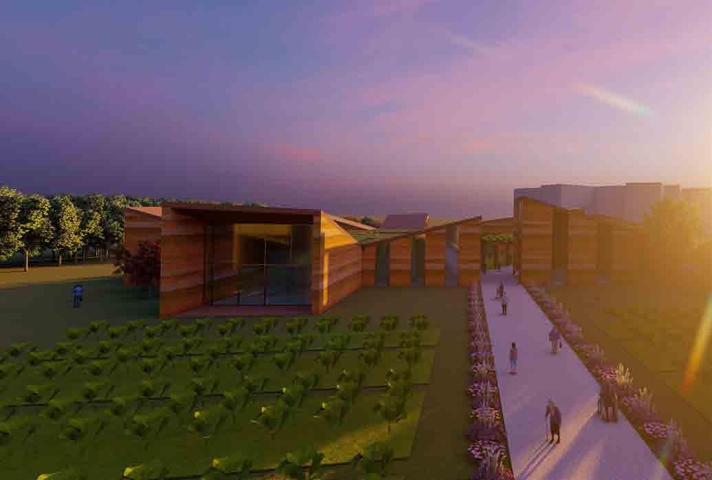
Re [charging] Community Health Hub and Sculpture Park
Rammed Earth made from Site Excavation and used in for hub
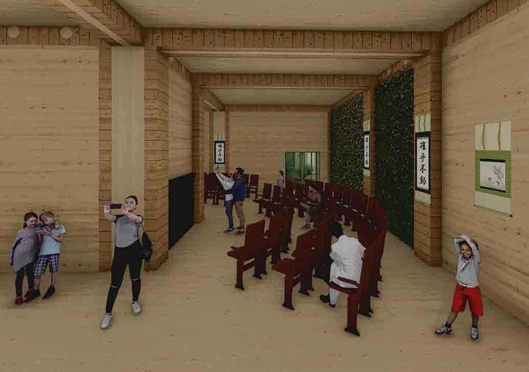
Creative Therapy, Sculpture Class, Interior Render
Village Green Sculptures Render
Step 4: All the additional layers of moist earth are added and then Stepcompressed5:Once dried the framework is being removed leaving the rammed earth wall
The chosen site had a slight slope therefore the earth has been removed and the topography has been flattened. Afterward, the removed soil has been used for the production od rammed earth walls and slabs for the re[charging] community hub.
HOW DOES TRANSFORMABLE ARCHITECTURE ENABLE ‘DESIGN AND REUSE’ THAT IS LOOSE-FIT AND CAN BE DISASSEMBLED FOR FUTURE USE


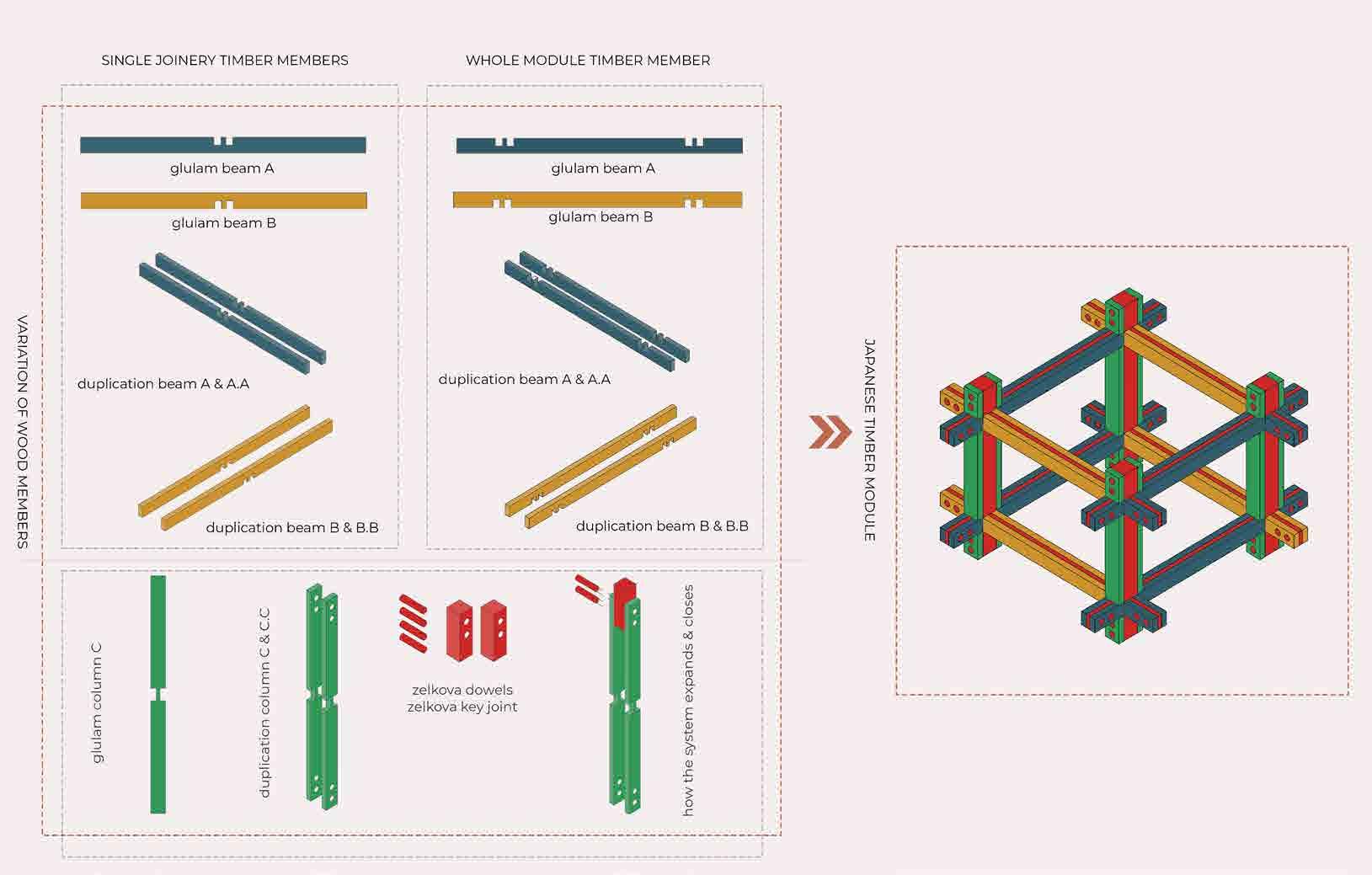
Assembly Sequence of Color Coded members (Studio Two)
Studio One focus was to design a transformable pavilion structure that is affordable, prefabricated, mass-produced, temporary and portable with no in-ground foundations offering extreme flexibility. The concept is based on origami-inspired corrugated cardboard shelter that can be a great temporary and instant solution for fast shelter. When the pavilion is not needed or must be transported, it simply folds up into a size. The cardboard origami pavilion is designed to be portable, lightweight, sustainable and naturally insulated.
From the Physical exploration of Japanese joinery, my research went down the path of digital testing to explore a structural system that was inspired by the old Japanese toy called Chidori. Developing my own Chidori system to be applied to any building type where no glue or nails are used allowing design for easy disassembly, relocation, and rearrangement. This structure aims to be flexible, adaptable, and easy to assemble and disassemble where the structural material will be glulam for the members, zelkova for the key joinery and CLT for walls, floors and roof. Timber is a sustainable renewable material that contributes to one of the objectives of this project which is designed for circular economy and reuse. The structure of the system will be modular off-site construction offering less labour, efficiency, less heavy machinery, minimal transportation, and wastage is minimised. Due to its flexible nature and ease to dismantle the system can give life to other buildings in the future or it can change its function and personality resulting in zero waste and longer life. Since it is prefabricated, it can be disassembled and relocated in different contexts meanwhile responding to technological, geological, environmental and cultural conditions. It becomes transformable architecture that can adapt to future needs.
10
FINAL YEAR, THESIS PROJECT, INDIVIDUAL WORK


(Studio Three)
In Studio One transformable architecture was defined as deployable kinetic moreover as a temporary collapsible structure that can be easily disassembled and transported from site A to site B and reused repeatedly. In Studio Two and Three, it is seen through a different lens as a permanent structure that can adapt to the future needs of the user and the unknown future allowing real-time reconfiguration and disassembly.
Prototype Form
The world is facing a massive climate crisis and we as architects must stand together against designing buildings for landfills we cannot continue to build the way we have if we want to be sustainable and save the planet.


By planning the design for future deconstruction and reuse, this project intends to be adaptable for accommodating future users, flexible not a fixed object that can be disassembled into parts giving new life to future projects and avoiding waste. Development of the Chidori Modules from a single Joinery (Studio Two)


Prototype Testing of Chidori Structure Potential use as a Pavilion (Studio Two) of Chidori Pavilion
THERE IS NO MORE SPACE.
Temporary Transformable Pavilion (Studio One)
Digital Experimentation of Folded Plane using Grasshopper (Studio One)

Digital Experimentation using Grasshopper (Studio One)
I am proposing to look at the transformable architecture with new eyes and as the door to a new way of designing that is loose-fit enabling design for the unknown future and design for deconstruction and disassembly (DfD) which is an alternative to demolition and waste. Transformable architecture can be many things from temporary redeployable structures that can be collapsed and easily transported to permanent adaptable and flexible building that awaits to be used again for new purposes. WE MUST STOP DEMOLISHING BUILDINGS.
Temporary Transformable Pavilion (Studio One) Area of Key Thesis Themes


3D Model of Site in Tokyo, Japan


Prefabricated Cross Laminated Timber Staircase Loose Fit Office Space dynamic urban dwellers”

Tokyo Modula provides spatial flexibility, allowing for creative space programming. As a result, it can handle a wide range of functions that can adapt and change over time. It provides a dynamic mix of commercial and socio cultural services, with the ground levels serving as the complex’s social hub, with a cinema, restaurant, shops, a coffee bar, and workspaces. Apartments of various types are mixed with branded smaller working spaces. Residents and occupants have the option of sharing automobiles and bikes.

Tokyo Modula is a sustainable and flexible mixed-used complex that is suitable for all age groups creating a cross generation living in the heart of Tokyo. Moreover, it will be creating shared living envi ronments for people of all ages, backgrounds, and living conditions. Tokyo Modula is suitable for people with disabilities, visually impairments and hearing impairments. The aim is to create a buiding that acts as a bridge between generations and people with disabilities, where each occupant has a special place in this community.
Massing Study of Tokyo Modula (Design Iterations)

South Sectional Perspective of Tokyo Modula (Studio Three)

“TOKYO MODULA ... a lively, future-proof complex as an iconic hub for
Second Floor of Tokyo Modula
Located in the eastern part of Asia, Tokyo is the capital and largest city of Japan. It is located at the head of Tokyo Bay, the region forms part of the Kanto area on the central Pacific coast of Japan’s main island of Honshu. Tokyo, Japan’s busy capital, mixes the ultramodern and the traditional, from neon-lit skyscrapers to historic temples as well as it is the largest urban economy in the world by gross domestic product and leading centre of business and finance.
First Floor of Tokyo Modula

Mezonet Green Terraces Balconies looking at Courtyard Greenhouses on the South Facade

11 The chosen site is located in Chuo city which forms part of the heart of Tokyo. It was formed in 1947 and it is divided into the three zones of Nihonbashi, Kyobashi and Tsukishima. Nihonbashi and Kyobashi are predominantly commercial areas on the east side of Tokyo Station. Tsukishima is a separate island in Tokyo Bay dominated by condominium towers.
Ground Floor Plan of Tokyo Modula
Multifunctional Hall and Event Space
Brief Programme Tokyo Modula (Studio Three)
Apartment
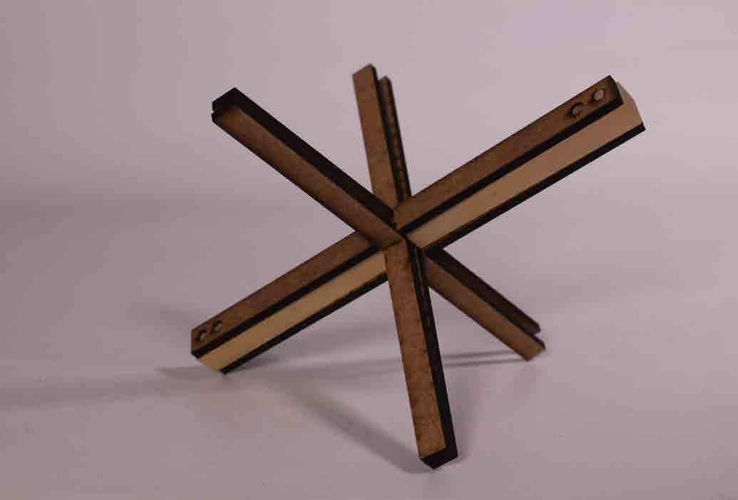
Physical Exploration of Japanese Wood Joinery (Chidori)Physical Assembly of Japanese Wood Joinery (Chidori)
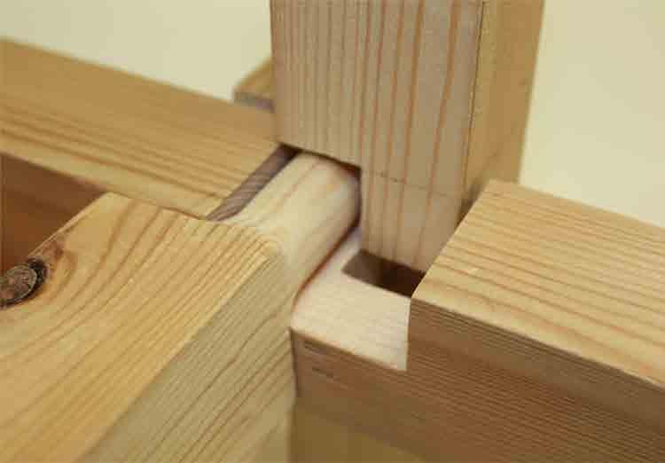
Instigated by the form of the existing Japanese wooden joint called Chidori where it carries the idea of wooden construction that does not require glue or screws making it easy for disassembly. It works as three pieces of wood interlocking with each other creating adaptable structure and spaces with the ability to accommodate various functions. The actual realisation of this concept is a simple picture in prin ciple, however, the actual creation and assembly of the joinery and connecting junction of each wooden block to one another is a very complex challenge that requires extreme accuracy and making skills.
Physical Model of Japanese Wood Joinery (Chidori)


Brochure of Own Chidori Joinery ‘‘Assemble it Yourself’’ (Studio Three)


12 Connection of Chidori Modules (Design Concept Expansion)
FINAL CHIDORI JONERY THAT WILL BE APPLIED AS A STRUCTURAL COMPONENT IN STUDIO 3
Comparison and Development of Chidori Joinery

Physical Model of Own Japanese Wood Joinery (Chidori)
ORIGINAL CHIDORI JOINERY APPLIED BY KENGO KUMA IN THE GC PROSTHO MUSEUM MODIFIED CHIDORI JOINERY FOLLOWING THE JAPANESE TECHNIQUE OF NO NAILS OR GLUE
Disassembly of Tokyo Modula, Kit of Parts (Studio Three)
Physical Model of Own Japanese Wood Joinery (Chidori)


Studio One focus was to design a transformable pavilion structure that is affordable, prefabricated, and mass-produced, temporary and portable with no in ground foundations offering extreme flexibility.

Tokyobuilding.Modula’s
STUDIO ONE (Application Cardboard Pavilion)
Deconstruction of Chidori Modules for New Purposes Scenario Two: Assembled as a Beach House (new location) Chidori Beach House Roof Terrace

Chidori Suburban House Interior View


Buildings are often created with one function in mind such as a shopping mall or an office or a housing estate, however, society needs, and their references change these mono functional buildings become obsolete resulting in high building demolition and waste. Demolition of buildings generates a huge amount of waste which is partially reused or recycled. Buildings should act as materials banks for new purposes, where they are a storage for valuable materials and components. A building that can be disassembled I parts and used again in a different
In Studio Three it has been applied to a large scale building that has residential / commercial function and then displayed in a different scenario in which the structure is deconstructed and transferred, albeit on a smaller scale.

Isometric View of Tokyo Modula (Studio Three)
Chidori Suburban House Exterior View


Scenario One: Assembled as a Suburban House
North Sectional Perspective of Tokyo Modula (Studio Three)
In Studio One transformable architecture was defined as deployable kinetic moreover as a temporary collapsible structure that can be easily disassembled and transported from site A to site B and reused repeatedly. In Studio Two it was tested as a pavilion medium scale.

Relocation of Tokyo Modula (Diagramx)

goal is to be adaptable enough to dismantle for future usage in situations where an imagined future scenario has been utilised. In the future, water levels rise due to climate change, and the Tokyo Modula is disassembled and transferred to two other areas, one suburban and one seaside, where it is repurposed as a two-story house.

STUDIO TWO (Application Chidori Pavilion)
STUDIO THREE (Application Tokyo Modula + Two Story House)
Design for Disassembly (DfD) of Tokyo Modula Showing Two Future Scenarios (Studio Three)
13

Venn Diagram Core Principles
Therefore in the end Transformable Architecture has been defined in a new way that challenges today’s way of thinking and designing.

14 Catalog Design It Yourself
Design Concept Digital Exploration of Chidori Joinery (own)


