5 minute read
PARAMETRIC BUILDING SYSTEM PRADA AOYAMA CASE STUDY

by ychen5

Course: Media and Modeling III
Instructor: James Park
Advertisement
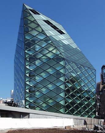
Location: Shanghai, China
Collaborator:
Yining Chen- Elevation Presentation+ Diagrid Analysis
Richard Fridy- Plan Presentation+ Interior Structure

Patricia Rangel- Section Presentation+ Massing Analysis
Spring 2020
For this assignment, students will work in teams. Each team will continue their study on the selected case study building by
1) identifying 3-4 critical building systems.
2) designing and implementing a parametric model for each identified building system.
3) illustrating the work with original diagrams and drawings.
The requirements of the parametric models: a) 1-3 photograph(s) of the building system with proper citation(s). b) a simple introductory diagram highlighting the key components, dimensions, and relations. c) a sample derivation visually describing the generative process in a step-by-step manner. d) the original design of the building system generated by the parametric model. e) a set of design variations of the building system generated by the parametric model illustrating the expressiveness (consistency and flexibility) of the parametric model.(Set and Get) and State GateDispatch.

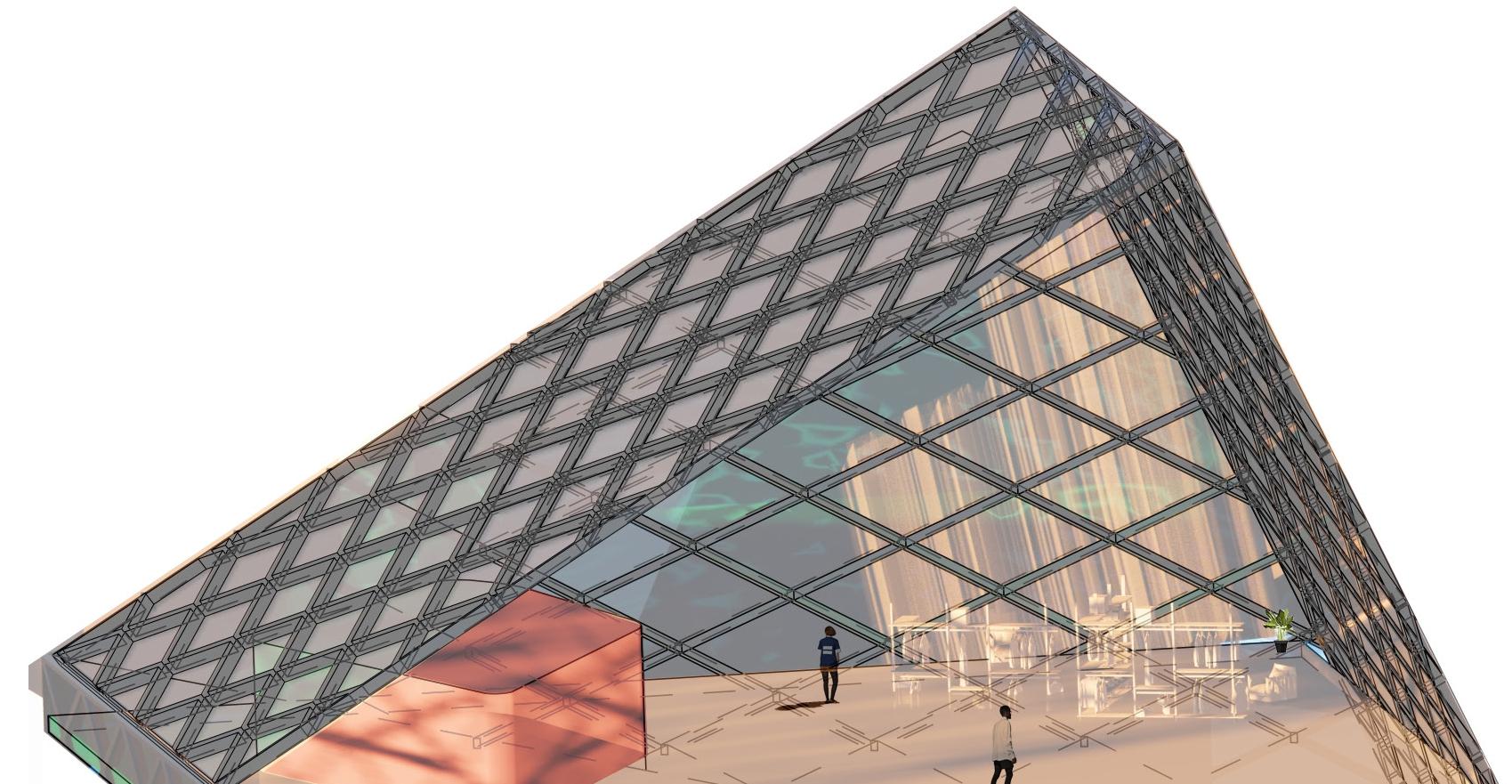
Reflection on Diagrids of Prada Tokyo Aoyama
Diagrid is an essential geometry of the building. Comparing our present understanding of the diagrids and the first day we started studying them, our thoughts on the diagrid change on two points: the sizes of the diagrids utilized as units on walls and roofs; the other is the forming process of diagrids.

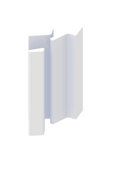
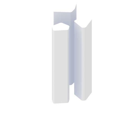
Projection lines traced between the segments described before frame the forms of the vertical chases that extend through the building.
side touching seam in the facade and the other reaching the middle of the opposite facade.
Parametric Design Variation- Prada Tokyo Aoyama
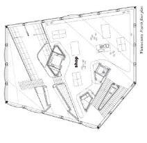
Annie Chen seen by these diagrams of the east and west elevation and sections, in the entirety of the building, only the second oor able maximizes the entire surface area the building’s footprint. The fourth oor because the third tunnel cantilevered on the east wall, though appears complete on the west wall. The fth oor, although not cantilevered, takes up smaller footprint due to the angle of the roof. Therefore the 2:5 ratio exhibits itself once again by establishing center of stability on the second of seven levels. piece of the massing the roof line that connects all the vertex heights to one of its two ends.
Our first speculation on these diagrids was that the shape of the diagrids on the walls and roofs was different in shape and size. Therefore when we first drew the diagrids, we treated them as various rhombic forms. There were five facades in total. Therefore we divided them into one diagrid unit for the walls and five others for different roofs. However, when we started to develop our diagrid system using the projection method, we realized there was only one diagrid unit for the whole cladding system. The diagrids on the walls are perpendicularly projected, whereas the projection on tilted planes causes the distorted diagrids on roofs. For our systems of diagrids, we used points and lines as basic units of our diagrids because we initially intended to treat the size of the diagrids as a parameter. With individual lines and points, we could easily change the sizes and shapes of the diagrids. We discovered that the diagrid could vary by following or breaking the original rule. The height and width could go by the ratio 2: 3.2, and all sides remain equal; or the regular proportion could be changed to another ratio; or the sides of the diagrids could be unequal to each other, which transforms the diagrids into an irregular net shape. However, it turned out that we used the original diagrid system and adapted it into different massings. As a result, the necessity of using points and lines as starting input was questioned. We wondered if there is a better way to begin the formation of the diagrid, for instance, starting with a single rhomb or an isosceles triangle. Further experimentation could be done by creating different geometries for the diagrid system.
- The centroid of Tunnel 1 is at the oor height 2H; the centroid of Tunnel 2 at the oor height 6H; the centroid of Tunnel 3 is at the oor height 8H. The distance ratio between the ground level and the centroid of these three tunnels are 2: 4: 2.
- Both Tunnel 1 and 2 begin from SPREAD 1 and ends at SPREAD 3, and both the distance from the beginning centroid to the end centroid of these two tunnels are 8L.
- Tunnel 3, unlike Tunnel 1 or 2, starts from SPREAD 1 and ends at Spread 5 which is adjacent to Spead 1 on the building, on the spread the distance from the beginning centroid to the end of the centroid is 17 L.
- According to the SPREAD, Each tunnel has a point hitting a corner of the building, Tunnel 1 hits the corner of the North and West facade (SPREAD 2&3), Tunnel hits the corner of the East and North facade (SPREAD 1&2), Tunnel 3 hits the South-West and South facade (SPREAD 4&5).
- From the observation of the glass types on the surface where all tunnels begin and end, most of the glasses are buble glass (to outside), therefore the visitors who traverse through the tunnel could see the outside world.
- Most glass panels on SPREAD 5 and partial glass panels on SPREAD 1 are smoky glasses, those are the facades for where the staircases locate inside the building.

- Most of the openable glasses are on SPREAD 1, 2 and 3. The ones on the vertical walls are re escapes. All the re escapes locate on the oors with height of 4H, 6H, 8H and 10H, the distance ratio between these oors are 2: 2: 2.
Inputs:
Input: Unfolded elevation with folding edges


Input
—Diagrid Lines —Edges of Vertical Chases (for alignment)
Parametric
Overview: is 9.
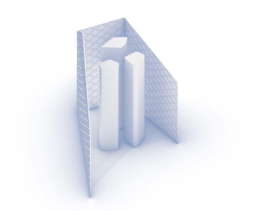
This system, still in progress, creates horizontal tunnels that function similarly to the vertical chases.
Instead of referencing the structural diagrid nodes and producing extrudable shapes through projection lines, the tunnels are extruded from the steel diagrid itself. Tunnels are varied by assigning differing start and end panels. Floor slabs are, in turn, trimmed by the intersections produced by these tunnels.
Step 1: Make the the first triangular set of points, set the gap length on the horizontal axis as 3200mm, and the gap length on the vertical axis as 2750mm. The number of horizontal intervals is 23, the number of vertical in-tervals 9.
Step 2: Create the second set of points as Step 1. Move them 1600mm to the right, then 1375mm up.
Step 2: Create the second set of points as Step 1. Move them 1600mm to the right, then 1375mm up.
Step 3: Connect the first set of points with the second in an one-to-two relationship.
Step 4: Connect the second set of points with the first in an one-to-two relationship. Step 5: Turn off the points and get only the diagrids.
Step 3: Connect the first set of points with the second in an one-totwo relationship, Step 4: Connect the second set of points with the first in an one-totwo relationship, Step 5: Turn off the points and get only the diagrids.
Variation: Roof Collage
Final Step: Project the diagrids onto the building.
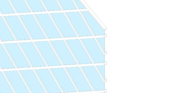
All diagrids are in rhombic shape which has the identical length of side. One diagrid, as module, determines the massing of the building in terms of the amount and size of it. The ratio of the shorter diagonal length of one rhombus to the longer diagonal lenght is always 2: 3.2. In the manner of the generative process illustrated above, the diagrds could keep expanding horizontally/ vertically to fit variety of massing (the prerequisite is that the massing changes in the unit of modules.) In all design variations, the diagrids expand in the horizontal direction in response to the length of the Nothern and Western Walls.


All diagrids are in rhombic shape which has the identical length of side. One diagrid, as module, determines the massing of the building in terms of the amount and size of it. The ratio of the shorter diagonal length of one rhombus to the longer diagonal lenght always 2: 3.2. In the manner of the generative process illustrated above, the diagrds could keep expanding horizontally/ vertically to fit variety of massing (the prerequisite is that the massing changes in the unit of modules.) In all design variations, the diagrids expand in the horizontal direction in response to the length of the Nothern and Western Walls.
SECONDARY SYSTEM- DIAGRID


