4 minute read
PARAMETRIC BUILDING SYSTEM

from Portfolio 2023_1
by ychen5

Prada Aoyama Case Study
Course: Media and Modeling III
Advertisement
Instructor: James Park
Location: Shanghai, China
Collaborator:
Yining Chen- Elevation Presentation+ Diagrid Analysis
Richard Fridy- Plan Presentation+ Interior Structure
Patricia Rangel- Section Presentation+
Shanghai Jiading Jiaxi Blower Limited Company (Manufacturer)
Spring 2020
This project aims first to explore the animation plugin in grasshopper, then flex an intricate Spatial Instrument in GH, utilizing dynamic analytical approaches for geometric construction and parametric operation. The limit of digital volume is 25m x 25m x 25m. In the volume, develop operable mechanisms that afford numerous modes of a variable input, relational hierarchies, dataflow logic, and behavioral differences. The required operations, approaches, and components are Global Values (Set and Get) and State GateDispatch.
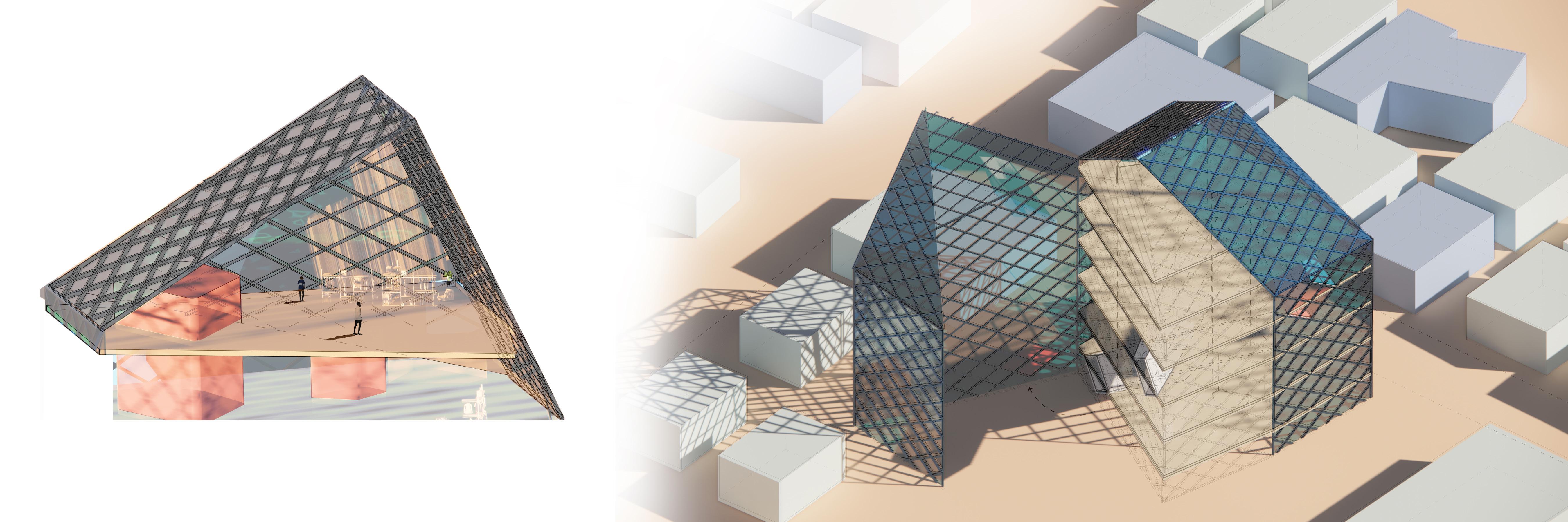
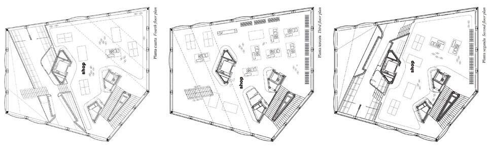
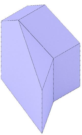
Parametric Design Variation- Prada Tokyo Aoyama
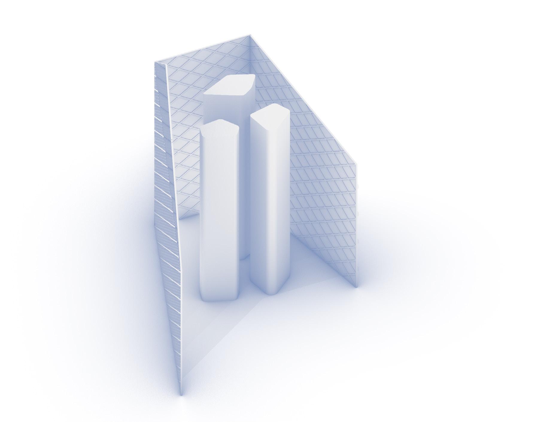
Projection lines traced between the segments described before frame the forms of the vertical chases that extend through the building.
in the facade and the other reaching the middle of the opposite facade.
- The centroid of Tunnel 1 is at the oor height 2H; the centroid of Tunnel 2 at the oor height 6H; the centroid of Tunnel 3 is at the oor height 8H. The distance ratio between the ground level and the centroid of these three tunnels are 2: 4: 2.
- Both Tunnel 1 and 2 begin from SPREAD 1 and ends at SPREAD 3, and both the distance from the beginning centroid to the end centroid of these two tunnels are 8L.
- Tunnel 3, unlike Tunnel 1 or 2, starts from SPREAD 1 and ends at Spread 5 which is adjacent to Spead 1 on the building, on the spread the distance from the beginning centroid to the end of the centroid is 17 L.
- According to the SPREAD, Each tunnel has a point hitting a corner of the building, Tunnel 1 hits the corner of the North and West facade (SPREAD 2&3), Tunnel hits the corner of the East and North facade (SPREAD 1&2), Tunnel 3 hits the South-West and South facade (SPREAD 4&5).
- From the observation of the glass types on the surface where all tunnels begin and end, most of the glasses are buble glass (to outside), therefore the visitors who traverse through the tunnel could see the outside world.
- Most glass panels on SPREAD 5 and partial glass panels on SPREAD 1 are smoky glasses, those are the facades for where the staircases locate inside the building.
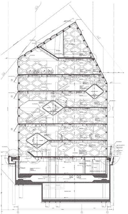
seen by these diagrams of the east and west elevation and sections, in the entirety of the building, only the second oor able maximizes the entire surface area the building’s footprint. The fourth oor because the third tunnel cantilevered on the east wall, though appears complete on the west wall. The fth oor, although not cantilevered, takes up smaller footprint due to the angle of the roof. Therefore the 2:5 ratio exhibits itself once again by establishing center of stability on the second of seven levels.
- Most of the openable glasses are on SPREAD 1, 2 and 3. The ones on the vertical walls are re escapes. All the re escapes locate on the oors with height of 4H, 6H, 8H and 10H, the distance ratio between these oors are 2: 2: 2.
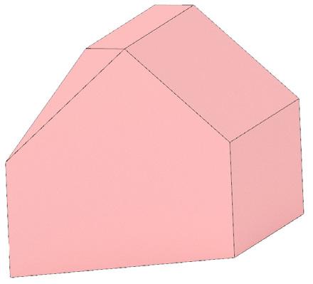
of the massing the roof line that connects all the vertex heights to one of its two ends.
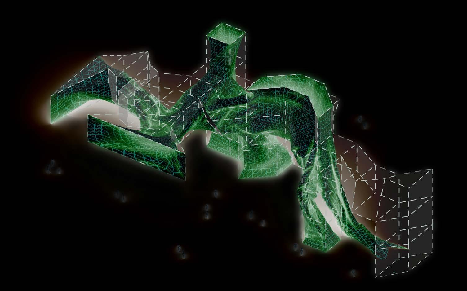
Inputs: —Diagrid Lines —Edges of Vertical Chases or alignment)
Parametric
Overview:
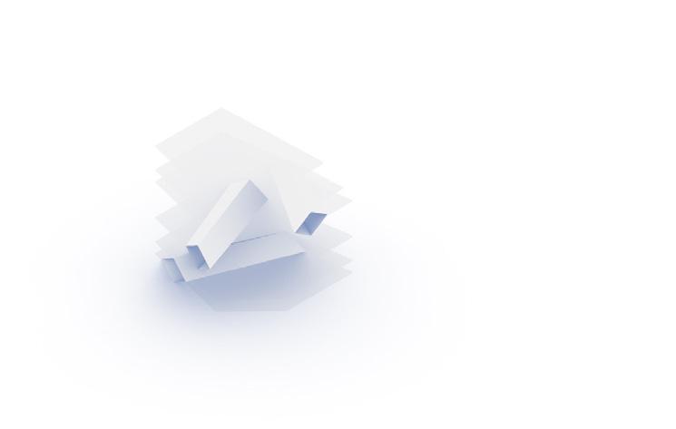
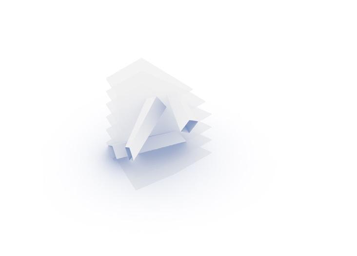
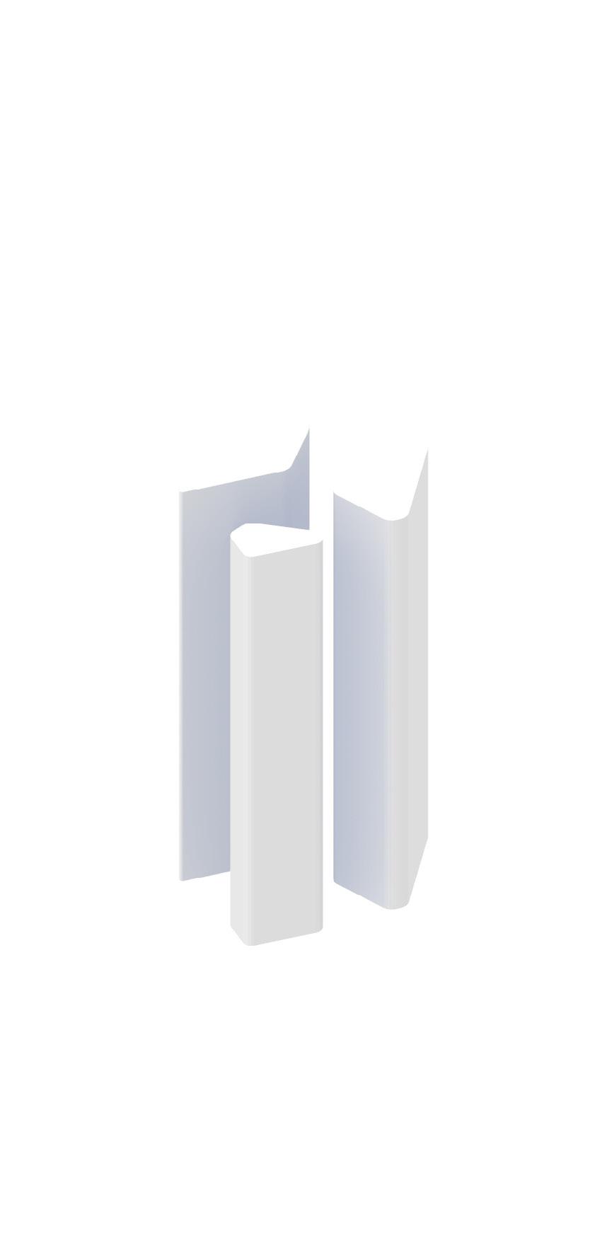
This system, still in progress, creates horizontal tunnels that function similarly to the vertical chases.
Instead of referencing the structural diagrid nodes and producing extrudable shapes through projection lines, the tunnels are extruded from the steel diagrid itself. Tunnels are varied by assigning differing start and end panels. Floor slabs are, in turn, trimmed by the intersections produced by these tunnels.
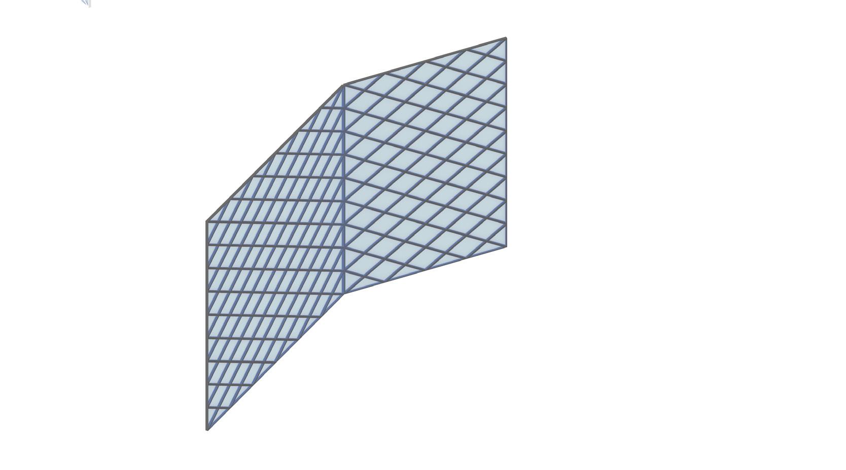
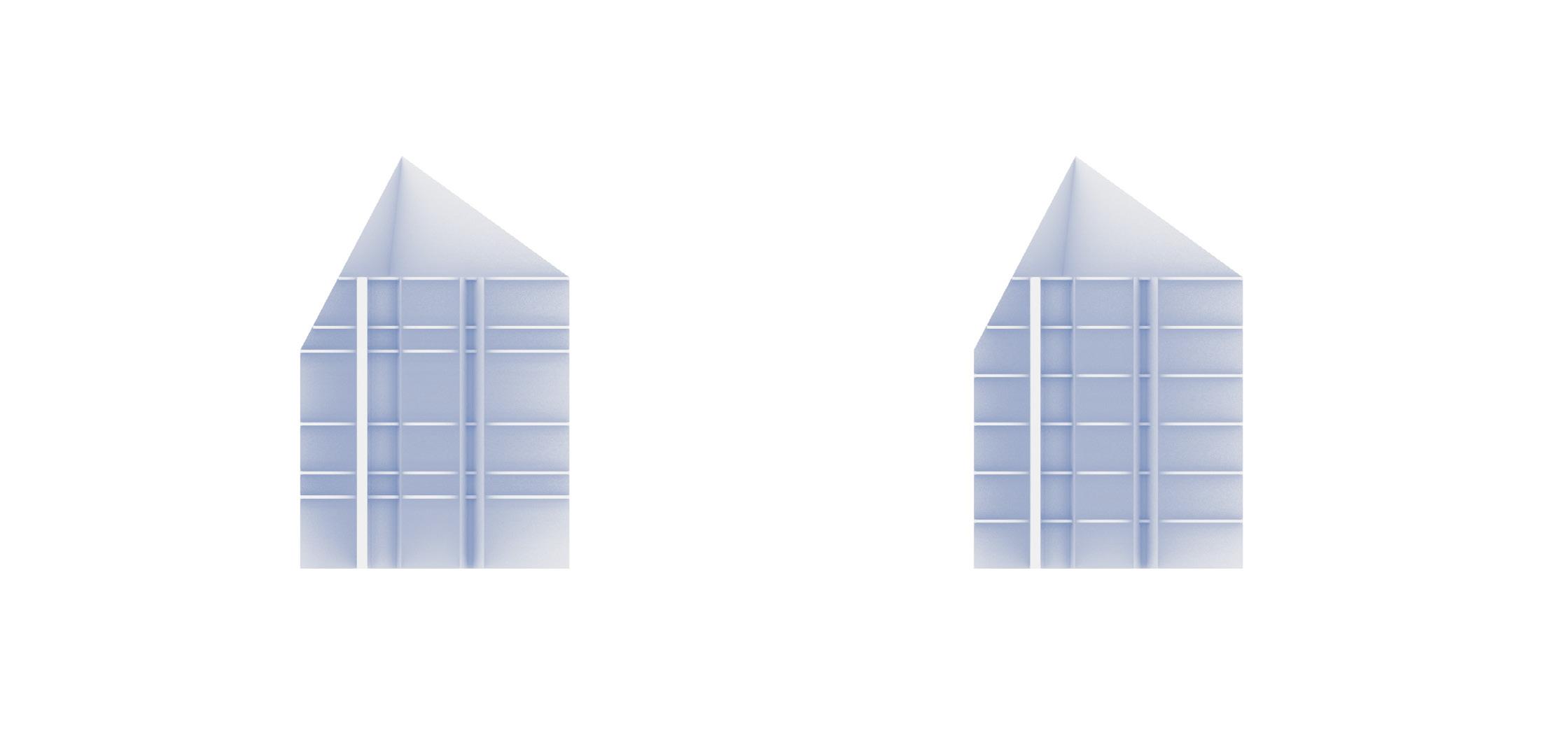
Input: Unfolded elevation with folding edges


Input is 9.
Step 1: Make the the first triangular set of points, set the gap length on the horizontal axis as 3200mm, and the gap length on the vertical axis as 2750mm. The number of horizontal intervals is 23, the number of vertical in-tervals 9.
Step 2: Create the second set of points as Step 1. Move them 1600mm to the right, then 1375mm up.
Step 2: Create the second set of points as Step 1. Move them 1600mm to the right, then 1375mm up.
Step 3: Connect the first set of points with the second in an one-to-two relationship.
Step 4: Connect the second set of points with the first in an one-to-two relationship.
Step 5: Turn off the points and get only the diagrids.
Step 3: Connect the first set of points with the second in an one-totwo relationship, Step 4: Connect the second set of points with the first in an one-totwo relationship, Step 5: Turn off the points and get only the diagrids.
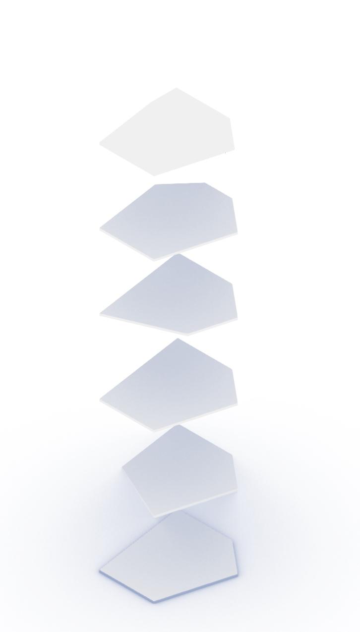
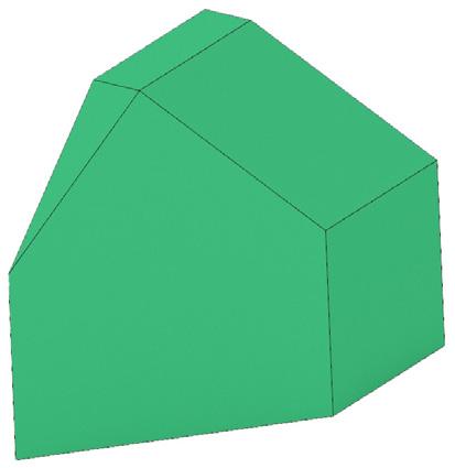
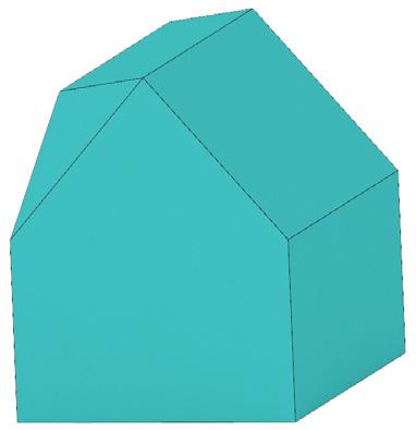
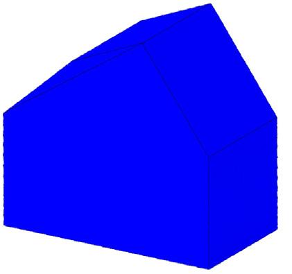
Variation: Roof Collage
Final Step: Project the diagrids onto the building.
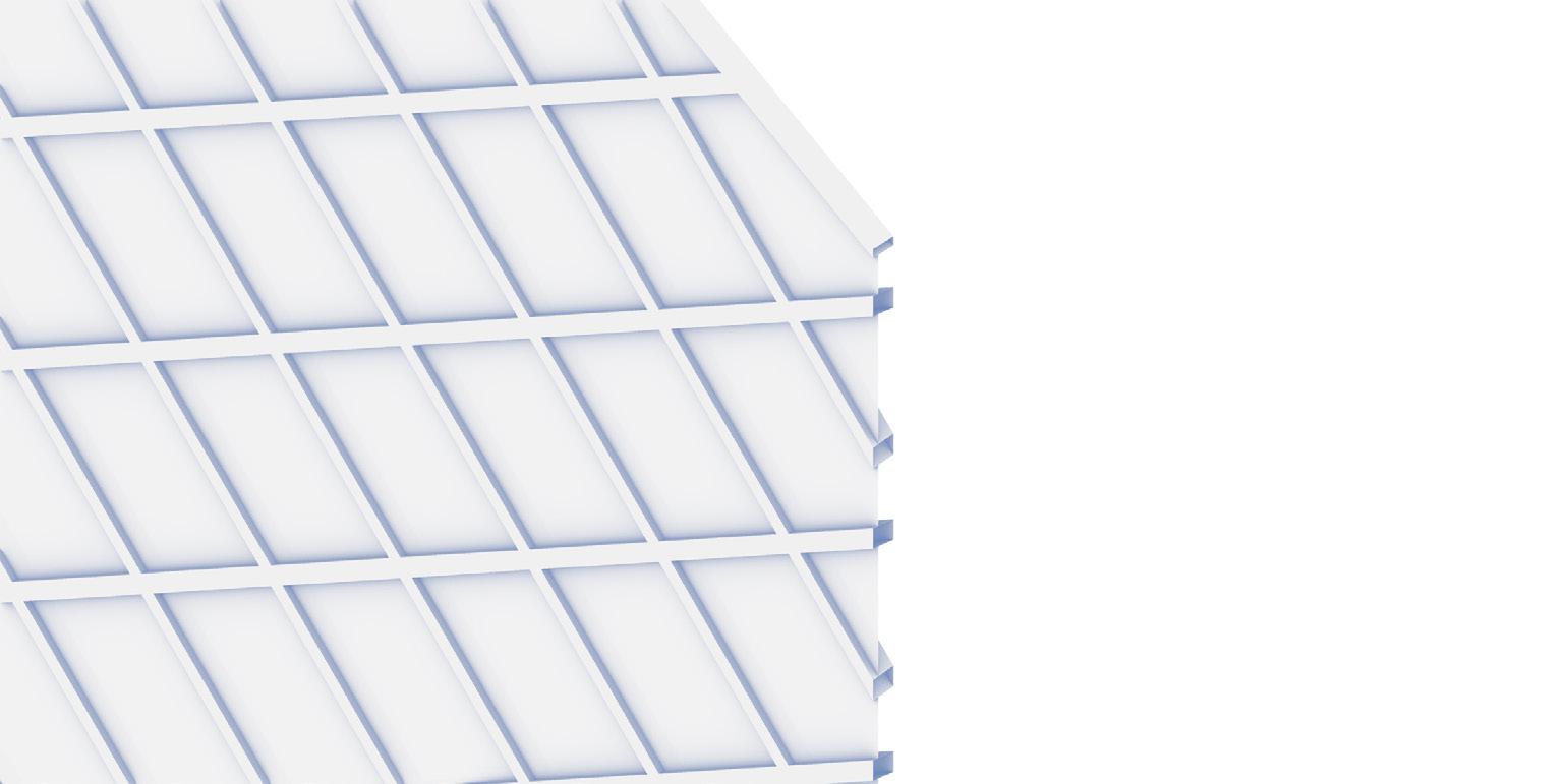
All diagrids are in rhombic shape which has the identical length of side. One diagrid, as module, determines the massing of the building in terms of the amount and size of it. The ratio of the shorter diagonal length of one rhombus to the longer diagonal lenght is always 2: 3.2. In the manner of the generative process illustrated above, the diagrds could keep expanding horizontally/ vertically to fit variety of massing (the prerequisite is that the massing changes in the unit of modules.) In all design variations, the diagrids expand in the horizontal direction in response to the length of the Nothern and Western Walls.


All diagrids are in rhombic shape which has the identical length of side. One diagrid, as module, determines the massing of the building in terms of the amount and size of it. The ratio of the shorter diagonal length of one rhombus to the longer diagonal lenght always 2: 3.2. In the manner of the generative process illustrated above, the diagrds could keep expanding horizontally/ vertically to fit variety of massing (the prerequisite is that the massing changes in the unit of modules.) In all design variations, the diagrids expand in the horizontal direction in response to the length of the Nothern and Western Walls.