PORTFOLIO YU-CHIAO HUANG SELECTED WORKS 2011-2022 For the Application to Architectural Computation (MSc) The Bartlett School of Architecture, UCL Application Number: 23094181

With over ten years of experience in academic and professional practice, Yu-Chiao Huang is a progressive and passionate learner seeking to broaden his vision in architecture research, especially in computation and studies. Based on his previous interests in digital tools and skills, he desires to improve his relational knowledge and face emerging data-driven issues in architecture practice.
National Cheng Kung University, Tainan City, Taiwan Sep 2016 – Feb 2018
Degree: Master of Science in Architecture
Thesis Design: “Architectural mass-customization for the mass: guiding design, representing and fabricating to the end user”
Tunghai University, Taichung City, Taiwan Sep 2011 – Jun 2016 Degree: Bachelor of Architecture in Architecture
Thesis Design: “The users city: adjusting hubs in local gaming”
Justin C. H. Shin Structural Engineer & Associates, Tainan City, Taiwan Feb 2019 – Jun 2022
Architect & Engineer, 4 years
• Analyzed and designed suitable structure reports and drawings by using structural model analysis tools to reach related requirements of the building codes.
• Developed the projects related historical environment by utilizing conserving and rejuvenating ideas. Assisted architects to examine the condition of buildings and to produce related suggestion reports and drawings.
• Provided architects with solutions of construction and structural problems.
• Completed approximately 50 projects during this career period.
United Technical Group Engineering Consultant Co.,Ltd, TaichungCity, Taiwan Jan 2015 – Feb 2015
Intern Designer, 2 months
• Analyzed the environment of the site and developed a schematic design about a residential housing.
Atelier Zhang Lei Architects, Nanjing City, China Jun 2015 – Aug 2015
Intern Designer, 2 months
• Analyzed the spatial organization with programs and developed a schematic design for competition about a kindergarten in Shanghai.
Registered Architect, Taiwan Taiwan Minister of the Interior, No.8093 Mar 2021 Public Construction Quality Management Engineer, Taiwan
Taiwan Public Construction Commission, No. IE1100301 Jan 2022
Taiwan 20 Selected Thesis Design Exhibition, Selected Award Jul 2016 Re-thinking the Future Sustainability Award, First Award Jul 2016 Cross-Straits Architecture Competition for Graduate Projects Award, Dept.Recommended Jul 2016 Far Eastern Architecture Young Talent Award, Dept.Recommended Jun 2014 Elite Freshmen Scholarship for studying Sep 2011 Monochrome Photography Awards 2020, Honorable Mention Jan 2021 5th edition of MonoVision Photography Awards, Honorable Mention Jul 2021
Designing Resilience in Asia International Research Programme, NCKUArch team Aug 2017 (collaborated with National University of Singapore)
THUArch Thesis Design Exhibition Jun 2016
Tunghai Innovators Expo Jun 2016
Taipei Maker Faire, THUArch & GoodWork team May 2015
NCKU Student Summer Seminar Structural Study Workshop Apr 2015 Tunghai in Rome Summer Program (collaborated with Cornell in Rome) Aug 2014
Tamkang Actuating Geometry in Design Workshop Aug 2014
Digital Fabrication Factory, Tunghai University Dept.Architecture
• Operated and maintained the facilities (3D printers and laser-cut machines) and also taught related manufacturing skills to students.
Processing Study Group, Tunghai University Dept.Architecture Student Association
• Hosted a Processing workshop and taught related scripting skills to students.
Part-Time Research Assistant, Tunghai University Dept.Architecture, Dr. Hao-Hsiu Chiu
• Assisted the professor to develop the prototype model research in parametric design.
Digital Fabrication Factory, National Cheng Kung University College of Planning and Design
• Operated and maintained the facilities (3D printers, laser-cut machines and CNC machine) and also taught related manufacturing skills to students.
Part-Time Research Assistant, Fu Jen Catholic University Dept. Landscape Architecture, Dr. Chi-Hsin Chiu
• Assisted the professor to interview related experts for research and survey.
Digital Drafting: AutoCAD/ Adobe Creative Cloud Suite
Digital Modeling: Revit/ Rhinoceros/ Grasshopper/ Sketchup
Digital Manufacturing: 3D Printing/ Laser Cutting/ CNC/ RhinoCAM
Digital Scripting: Python/ Processing/ Arduino
Digital Analyzing: Midas/ Etabs
Thesis Design/ National Cheng Kung University/ 2nd year/ 2018
Thesis Design/ Tunghai University/ 5th year/ 2016
Studio Project/ Tunghai University/ 4th year sem7/ 2014
Studio Project/ Tunghai University/ 4th year sem8/ 2015
Studio Project/ Tunghai University/ 3th year sem5/ 2013
Actual Project/ Justin C. H. Shin Structural Engineer & Associates/ 2019-2022


Thesis Design/ National Cheng Kung University/ 2nd year/ 2018 Advisor: Tay-Sheng Jeng, Kane Yanagawa tsjeng@mail.ncku.edu.tw / kyanagawa@mail.ncku.edu.tw
Thesis Fulltext File Link: https://thesis.lib.ncku.edu.tw/thesis/detail/dddba090dc489bd72f6afee775b15668/
While the concepts behind Web 2.0 website development emphasized ease of use, usergenerated content, and collaborative networking leading up to what is collectively called "social media, the discourse surrounding the "Maker Movement" and "Long Tail" economic shift revolves around the transition of this "social" revolution out of digital media and into the physical realm. This research identifies how technological advancements, such as digital fabrication, 3D scanning/data collection, and parametric design strategies in the architectural field, converge to provide an aided-creating design means to bring mass-customization to the masses.
First, the user study reveals a few common issues about the DIY process. There is a gap between the user's idea and fabricating methods. Therefore, this research proposes an interactive workflow for those makers. Corresponding to the "Maker Movement" and "Long Tail," the research translates the user's requirement into an interactive graphic interface and real-time CAD preview. Furthermore, it can connect to the CAM process to generate the ready files, produce these parts and assemble them by the user. "User-Generated Architecture," as an interactive creating tool, provides a new framework for this research to develop: UX ( user experience ) / UI ( user interface ), representing, fabricating, and assembling. The main challenge is building this tool with a "lowbarrier" requirement for the user and proving the design on quality. At the end of the proposal, the ambition is to promote this workflow to the level of the mass-customization, from furniture and interior design to customized housing projects.
This study tests the ability of "User-Generated Architecture" in the different exercises. The current results indicate a potential for simple general arrangement planning layouts and 3D space preview displays. Meanwhile, inexperienced and immediate users have various exceptions and use different regenerating counts: a universal or
customized design. The reason could be caused by how easy to fabricate it. Although this study can provide design-decision navigation and free customized drafting for users, there still is a gap in free customized fabrication. Because of the limitation of the material study, the final work cannot reach the original exception result. However, only the "computer-aided creating" process can ensure one thing. And that points out the difference between making and designing. This thesis would offer the development direction for the future.
To reach the mass-customization, we need to take care of the universal users. Therefore, the user interface is a flexible tool for everyone to adapt quickly through user experience study. Then, this UI needs to follow the fabrication machine. To have the mass-customization the most effect, it depends on the creativity of the process. Ultimately, this research raises the importance of "Computer Aided Creating."
Every individual building should be a customized architecture. In an actual architecture design project, the client asks for an architect to design a building as a technical service. On the other hand, the architect views the building as his discourse practice. They sometimes argue between the client's requirements and the designer's desires. In this separate situation, this paper focuses on the client-driven project. As the user can learn to cook on social media like Youtube, this research proposes an easy tool for the non-background user to complete a design and learn design for emerging customized work.
In regular architecture work, design and construction are assigned to two different professional teams. A building project includes SD (Schematic Design), DD (Design Development), CD (Construction Documents), and CA (Construction Administration), which architects dominate. During the process, architects have their consulters solve building problems in the final document. And the client takes these files to match a construction company for implementation.
By using "User-Generated Architecture" to generate output, the user can have a quick preview in 3D model rendering. Observing the form, the user can make the design decision to go next or back to modify. After the design processing, the tool generates the CAM (computer-aided manufacturing) files and connects the fabrication machine (ex. 3-axis CNC, 6-axis Robot, etc.). The user only
needs to prepare the material and presses the operation buttons. It's different from the traditional workflow requiring manpower and craftsmanship. In processing CAD to CAM, the tool would first apply the default settings, the simple assembly. It ensures those inexperienced users against failing their work. When the immediate level designer utilizes this tool, he can do the advanced manufacturing and assemble in his settings. With Wikihouse's significant contribution, they implement user fabricating housing for these years. At this moment, the paper inspires users to address their idea, comprehend the know-how of the design and realize the customized design in the end.
The existing workflow is a time-consuming task. However, the stages of the workflow are evident in programs. It is the opportunity to compile into an application for real-time representing the output drawings. Only one thing has to do to ensure the base building requirement, such as escaping code, structure condition, environment quality, and so on, matches the limited standard.
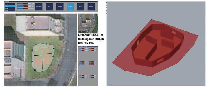
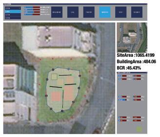
This research portrays an individual housing design that could be built up quickly by "UserGenerated Architecture." The user can use the application with a friendly GUI (graphic user interface) to draw the building layout under the inner building code restrictions. With this effective design decision-making tool, these CAD files are easy to transfer to CAM files, just like the client taking the final document to the factory and assembling it as the builder.
The Agenda Setting in the Processing of the Research Thesis Overview"User-Generated Architecture" Workflow
The Issues of "User-Generated Architecture"
Representing
Non-background users usually can realize the design by visual simulation in 2D drawings, but most in 3D renderings. As a result, utilizing the Processing to generate interactive graphics with evaluation results, through UDP routine to Grasshopper modeling, the original object-type data can rebuild in 3D CAD software easily. At this moment, the user can play the client role in deciding the ideal design, like choosing the product in his favor. Then, the user employs the present CAD model in Rhinoceros / Grasshopper to execute the manufacturing processes.


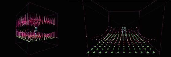
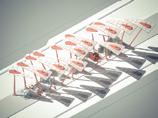
In this part, this research tried to apply the "Kinect" sensory to collect the body measurement. The development program imports "OpenNI" as the main library. There
are two kinds of algorithms: skeleton system and point clouds system. The skeleton system identifies the body by 15 joints. Kinect cameras also can capture the joints' location in the active environment. Processing can draw this interaction situation in the virtual environment. Therefore, we can set some factors to respond to the user's postures in real-time. The point clouds system identifies the object by depth reflection sensory. Rebuilding these points' location, Kinect can outline the object's figure.
The significant feature of the Processing language platform in programming is a continuous for-loop mode. The program can refresh the input and generate the output through the for-loop effect.

void sendMessage() { StringList list; list = new StringList(); if (pts.size()>0) { list.append("#"+String.valueOf(pts.size())+"#"); for (int i=0; i<pts.size(); i++) { Points p=pts.get(i); list.append("#"+String.valueOf(p.x)+"#"); list.append("#"+String.valueOf(p.y)+"#"); } }
message =list +" "; udps.send( message, ip, port );


UDP Send and Receive, String to Objects


PVector joint_HEAD=new PVector(); context.getJointPositionSkeleton(userList[i], SimpleOpenNI.SKEL_HEAD, joint_HEAD); PVector att = new PVector(joint_HEAD.x, joint_HEAD.y, joint_HEAD.z); for (int d=0; d<grids.size(); d++) { PVector nLoc=(PVector)grids.get(d); strokeWeight(30); float distance = PVector.dist(nLoc,att); stroke(255,0,map(distance,0,6000,50,255)); point(nLoc.x,sq((distance)/100)-boundSize/2, nLoc.z); point(nLoc.x,-sq((distance)/100)+boundSize/2+300, nLoc.z); strokeWeight(10); line(nLoc.x,sq((distance)/100)-boundSize/2, nLoc.z,nLoc.x,-boundSize/2, nLoc.z); line(nLoc.x,-sq((distance)/100)+boundSize/2+300, nLoc.z,nLoc.x,boundSize/2+300, nLoc.z); Kinect Recording Link: https://youtu.be/06wH3O9vEak

Visual Representing In Real-Time


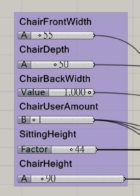
Types of Input Parameters
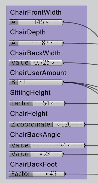

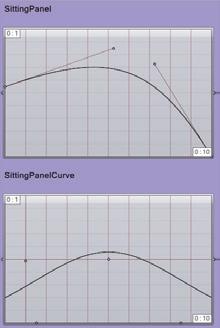
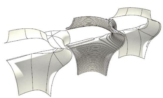
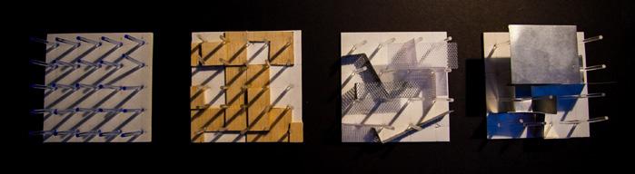
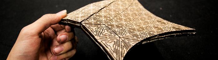
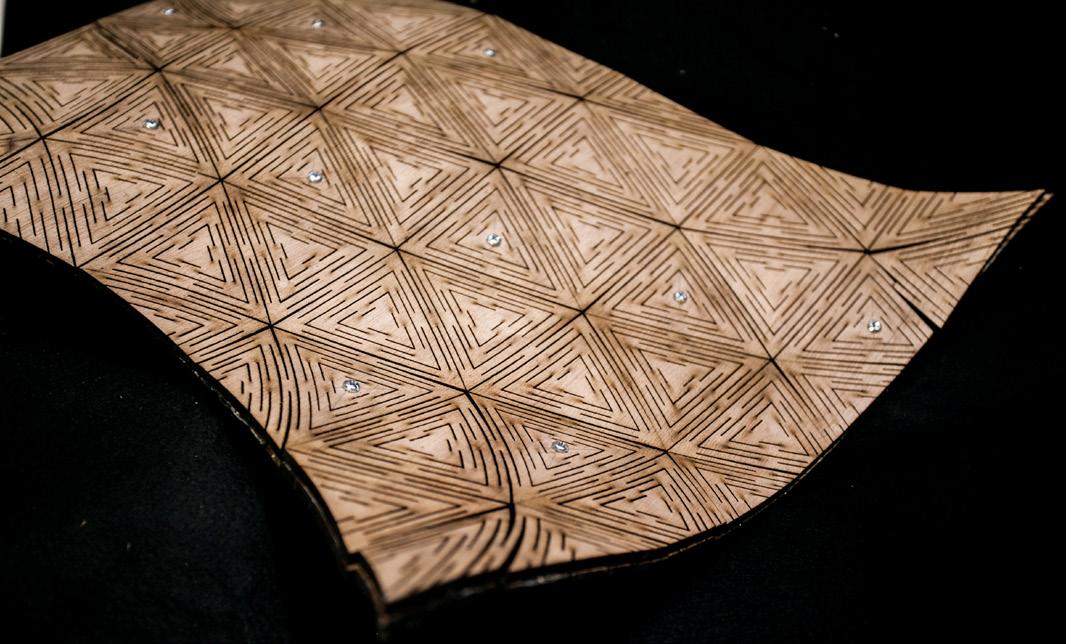
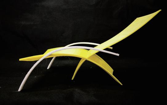
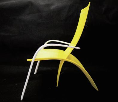
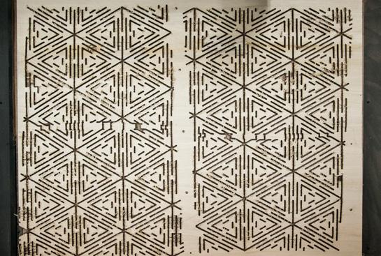
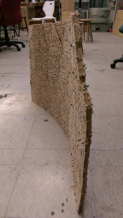
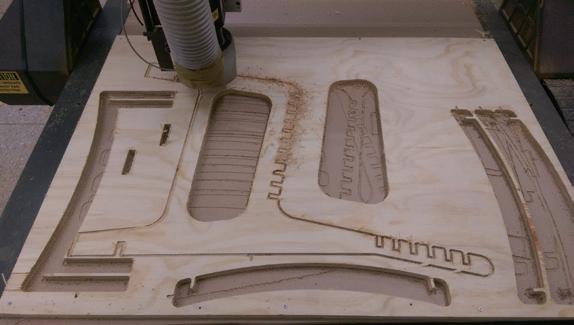
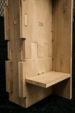
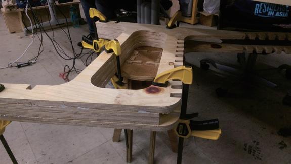
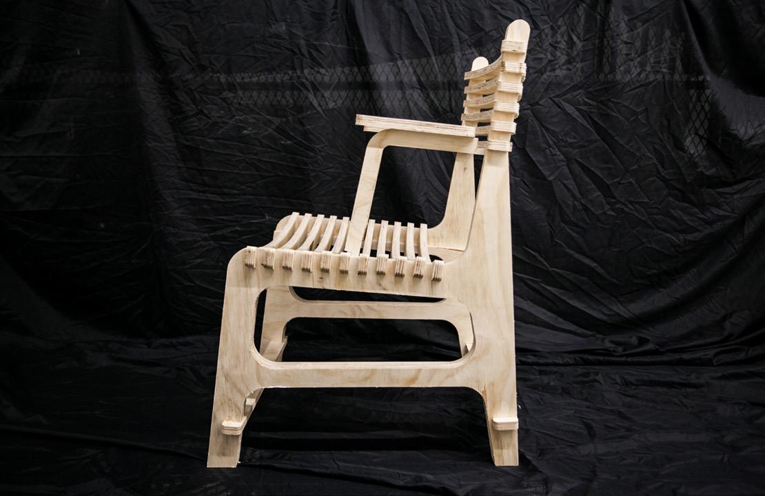
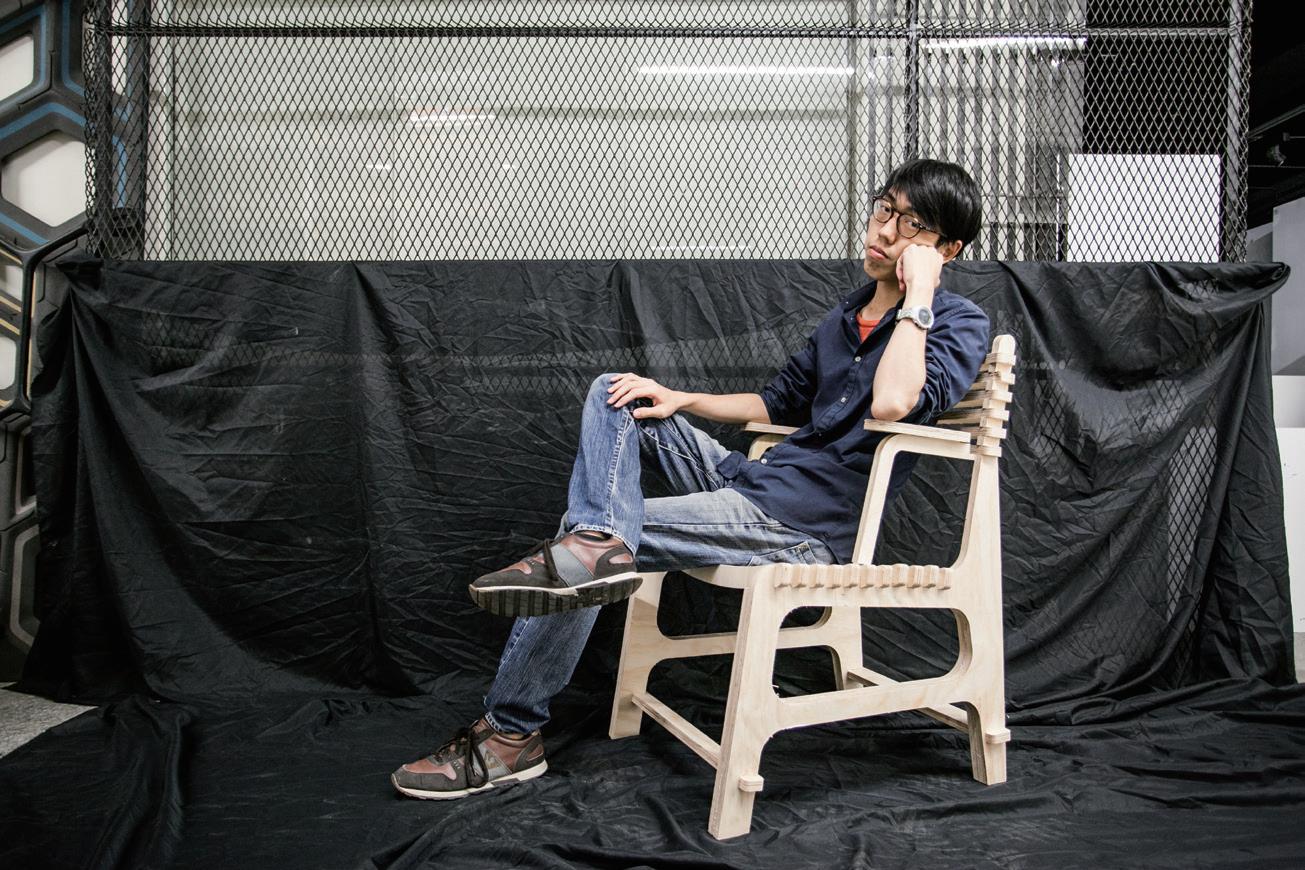
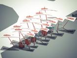
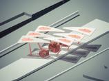
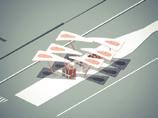
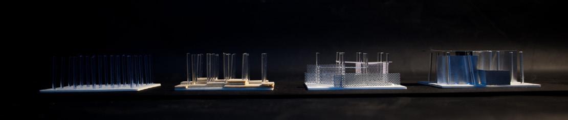
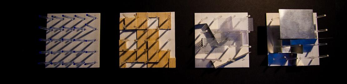
Although 3D printing can do in a rapidprototyping manner, this research focuses on 2-axis CNC manufacturing. Because of the material performance, CNC manufacturing can test the design results in the research development processes. In this case, the research applies the mass-customization design in the parametric chair design. Owing to the multiple-direction curved surface, the study references the “living-hinged pattern.” The interesting thing is the board changes its properties with these cutting patterns. That makes the wooden panel can be bent into a curved surface easily. Also, the morphing patterns can define the final form and be controlled by parameters in Grasshopper. The research studies the fabrication from the microscale in the laser-cutting model to the actual scale in CNC manufacturing to approach a stable mass-customization performance.
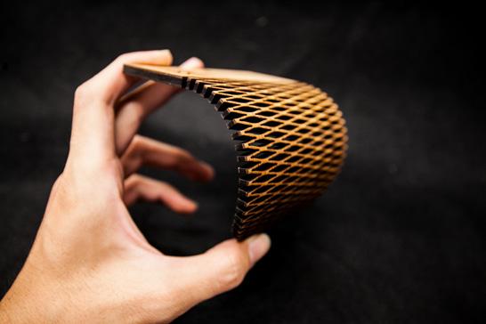
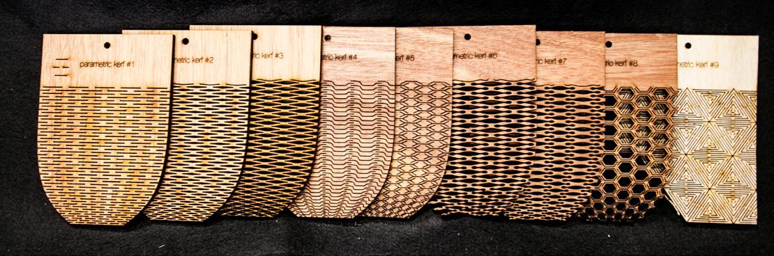
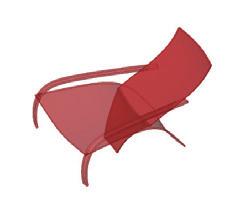
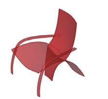
This part tests the possible ways to complete CAD to CAM. Based on the fabrication study, this exercise applies the "living-hinged" folding patterns on the surface. It utilized the
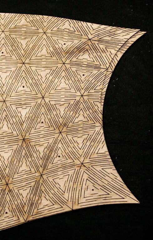
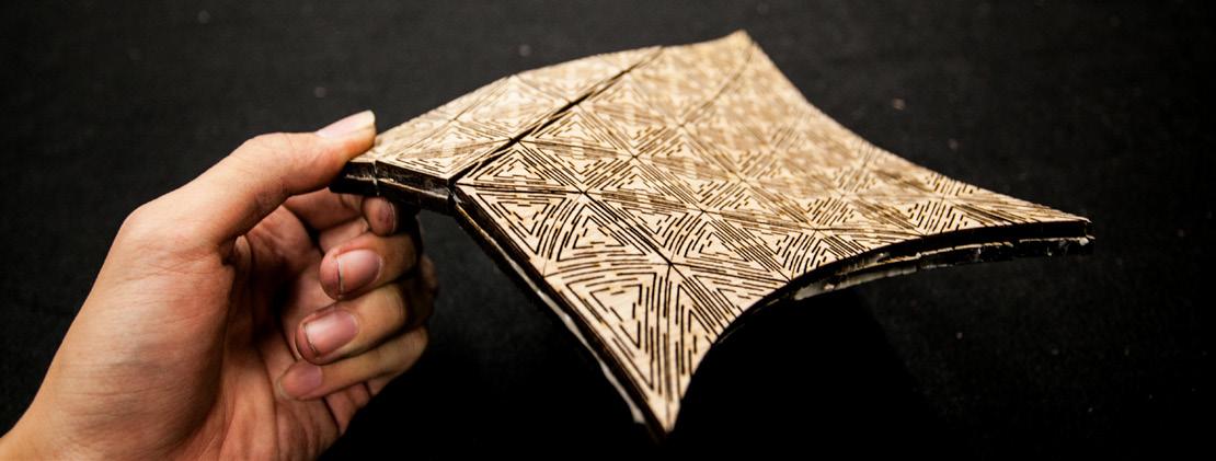
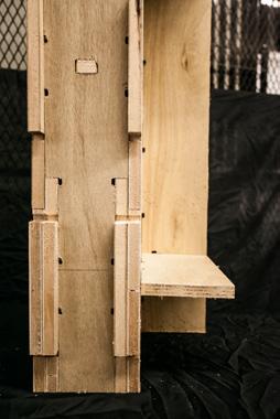
commands in Rhinoceros, from 2D planer triangle patterns using the curve to the surface, offsetting the surface, and then squishing the surface. The results are two similar liner geometry and can be assembled by matching the edge's length to define the curved surface. In the 3D representing, the centers of the triangles are the fixed points, so the user can use bolts on it to complete the assembly.
Wooden Cruved Surface (Living-Hinged)Drafting to Manufacturing
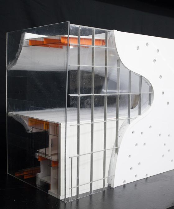
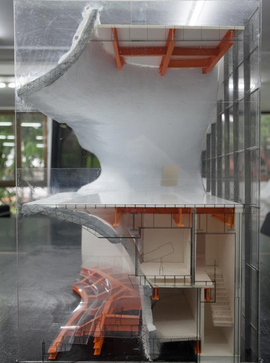
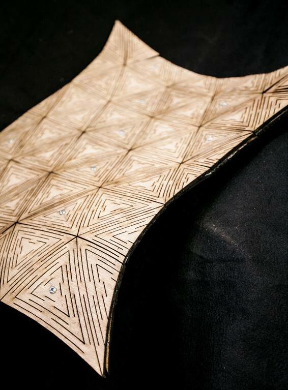
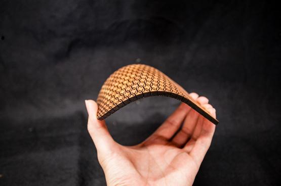
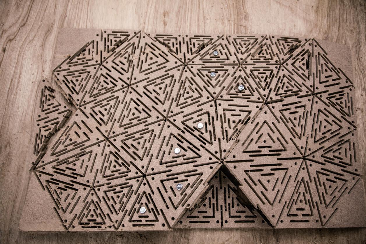
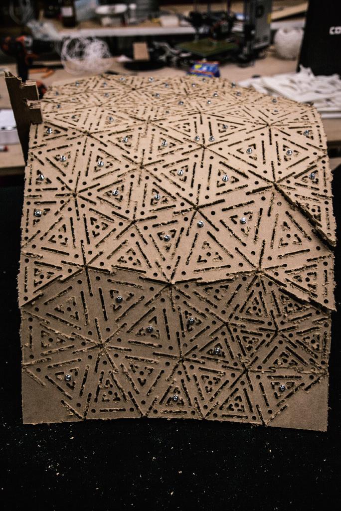
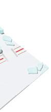
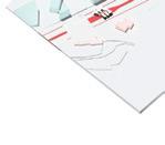
Before the actual scale testing, this exercise uses laser-cutting to test the fabricating model. After the cutting, this fabricating authentically changed the material properties from the planer to the curved surface. The surface can be stretched by the spacer between the incisions. The glue and the bolts fix the multiple-direction curved surface.
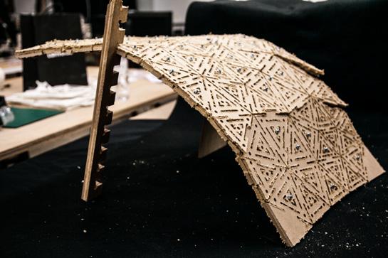
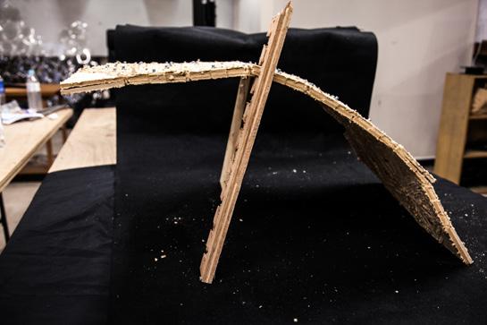
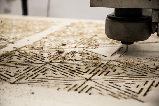
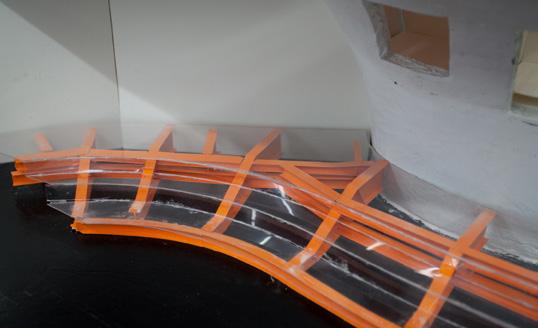
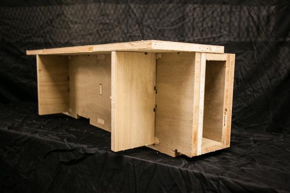
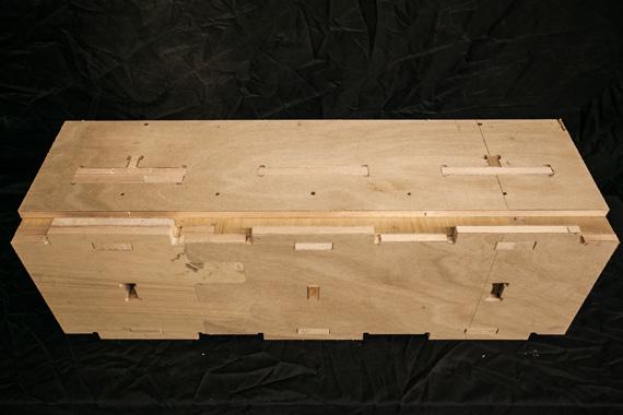
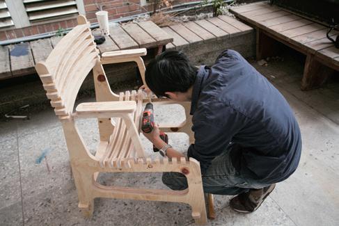
After the former testing, the actual scale testing needs to study the material first. This case failed
to use 9 mm plywood 2pics and 10 mm Medium Density Fiberboard 2pics. The closest one is 6 mm Medium Density Fiberboard 2pics by small triangle size patterns ( edge size 9-13cm ). Although this test manufactures the curved surface in the end, it still cannot reach enough strength for support. However, the study can continue to develop to find suitable material and future patterns.
Customized-Chair CNC Testing Laser-Cutting Prototype Model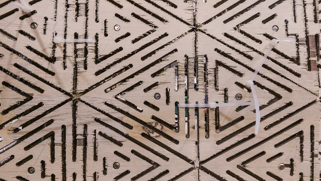
Considering the users' ability, the final output should notice to transform into simple parts of members assembled by common tools or just one tool. Referring to" Wikihouse," the clear construction logic prompts those users to exert their manpower as professional workers. The research proposes the design results like a DIY product bought from IKEA. Reviewing the mass-production, the real estate industry has developed prefabricated housing. At this" maker movement" moment, the thesis intends to improve individual housing from industrial-module design to mass-customization.
Thesis Design/ Tunghai University/ 5th year/ 2016 Advisor: Tien Ling tienling@arch.nycu.edu.tw
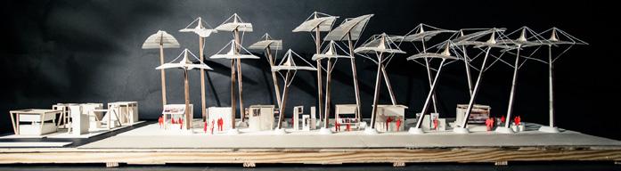
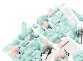
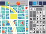
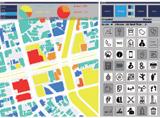
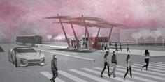
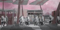
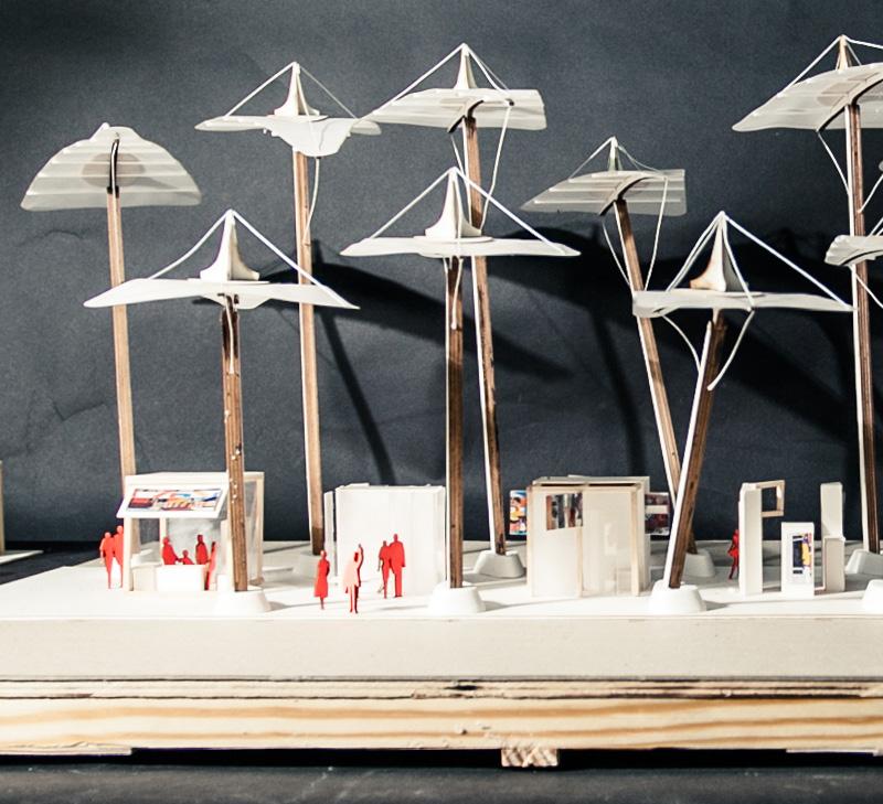
This project tried to find a way that the public could create the urban space not by architects but by themselves. A common space should offer flexibility to the public, who can edit it. In the end, this project imagined the city would be full of many positive activities at any time.
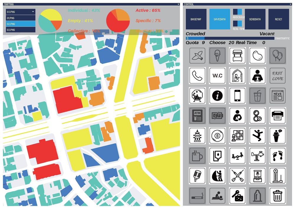
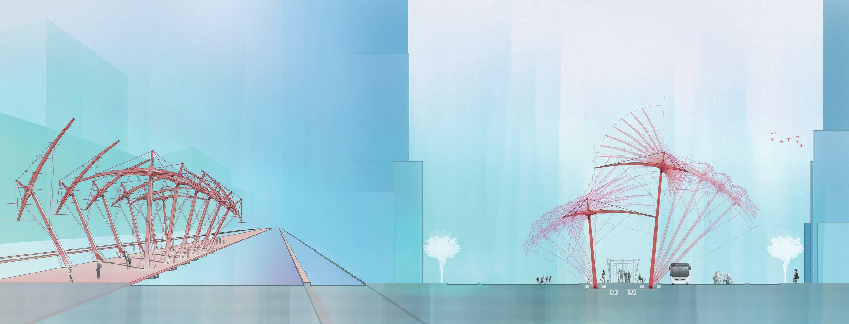
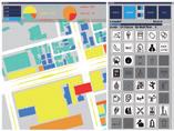
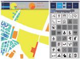
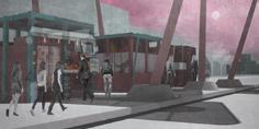
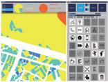
This design developed an interactive-application program to operate the urban space design. The program included installing open rules, creating the urban context, and collecting urban data. The final result is an interactive bus station design.
The thesis design followed these four main concepts:
The maximum the urban space
Urban is a huge structure, collecting many complex systems parts.
The maximum the urban time
Urban is a non-stop change at any time. The old space is erasing, and the new area is overlying.
The minimum the urban space
The daily programs do the minimum units, composed of many spatial program modules. We create abstract spatial frames, filling the concrete urban activities into them.
The minimum the urban time
Urban information is changing in real-time. We use the input data in real-time, transforming and performing in the space forms. Furthermore, the users will dominate the tone of the urban spaces.
Gaming is a common language for the public. We can use this method to connect the designers and the public.
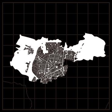
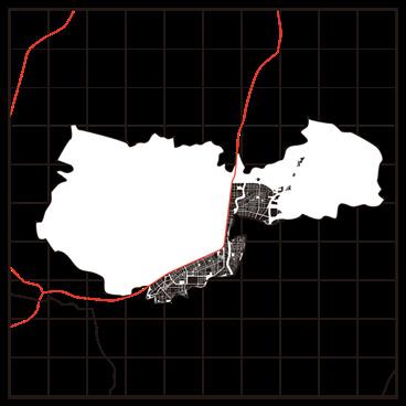
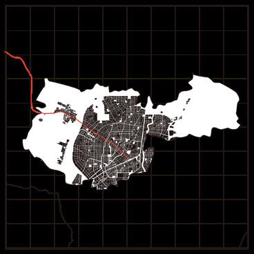
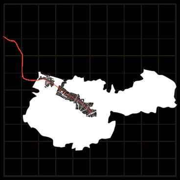
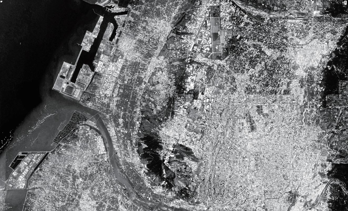
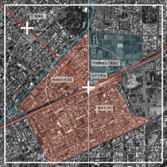
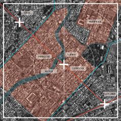
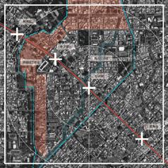
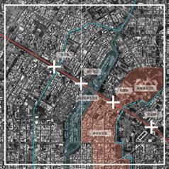
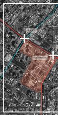
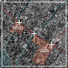
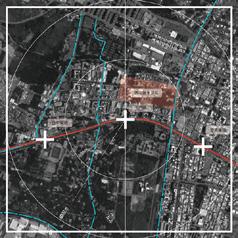
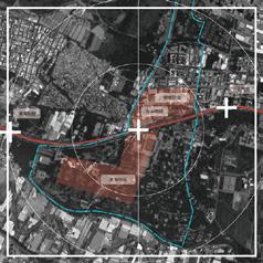
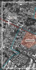
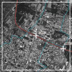
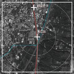
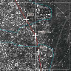
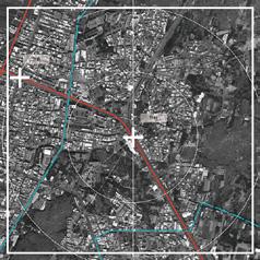
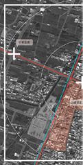
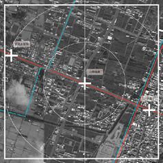
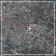
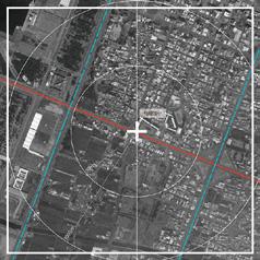
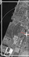
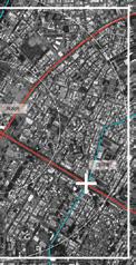
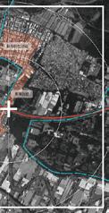
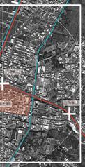
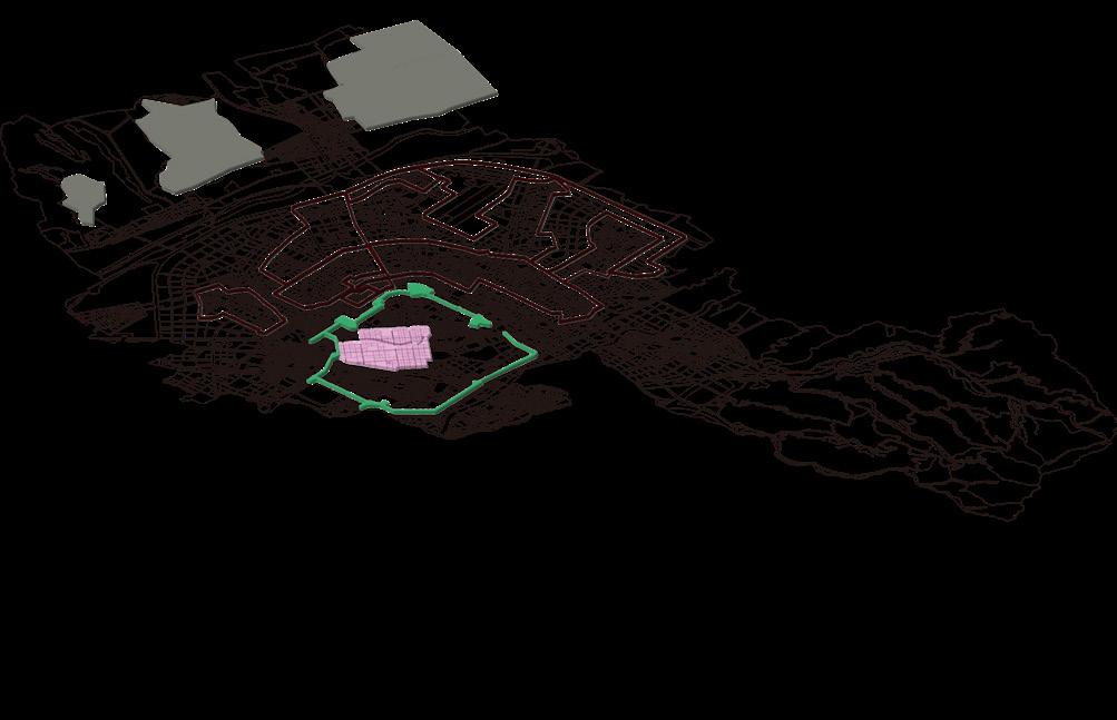
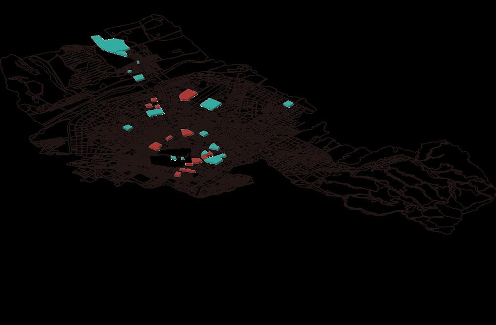
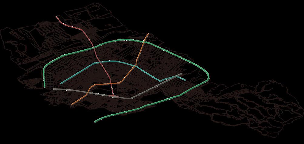
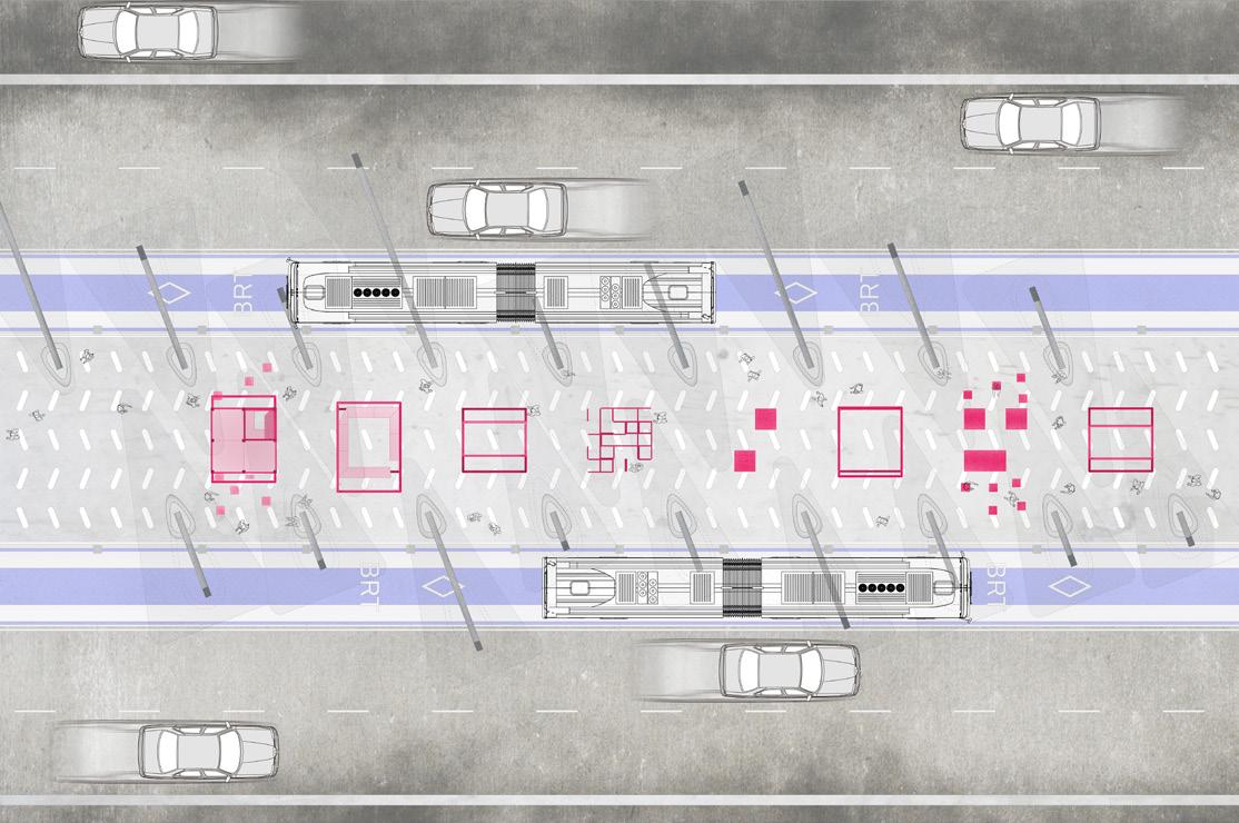
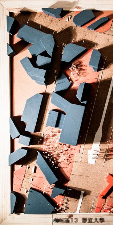
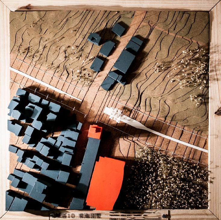
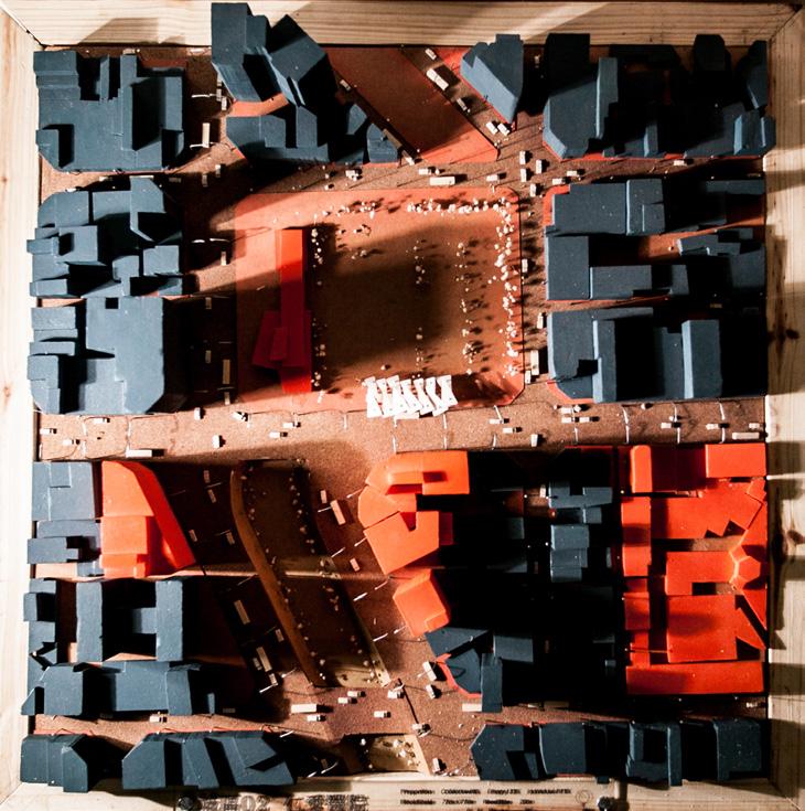
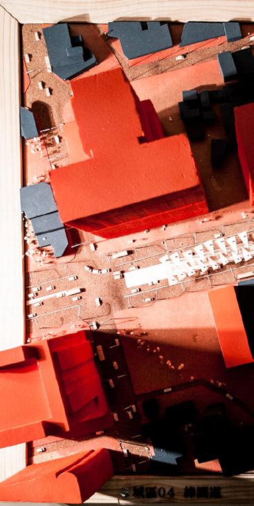
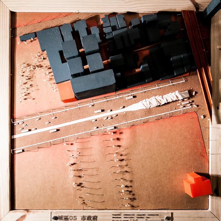
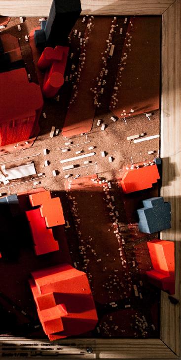
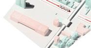
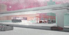
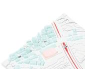
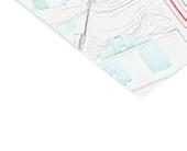
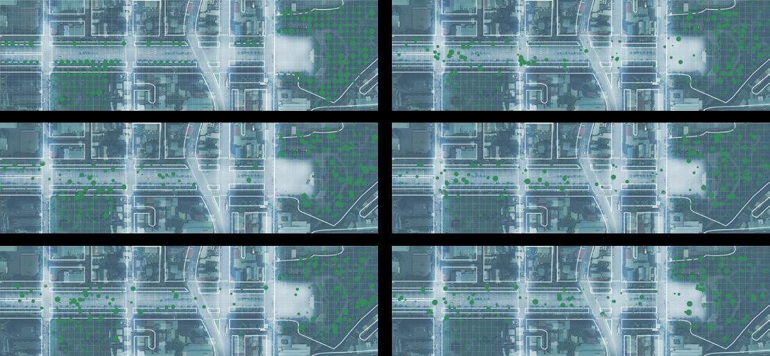
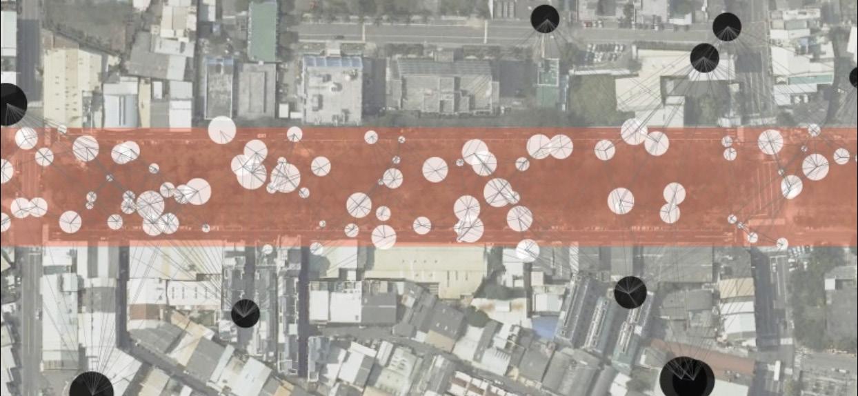
The site, Taiwan Boulevard, is the main road in Taichung City ( in the middle of Taiwan ). It starts from the train station ( inside the city ) to the port ( the far suburb ). It also displays the different faces of the city. The city is a non-stop expansion, but it is an empty city. Builders created many buildings
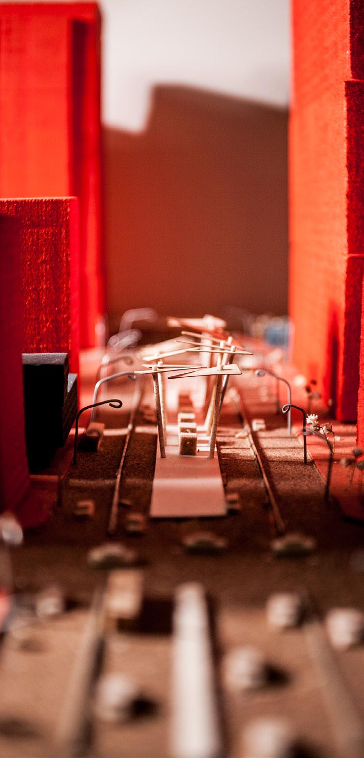
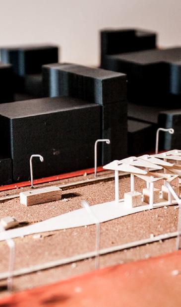
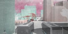
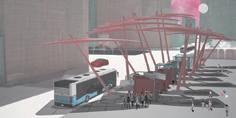
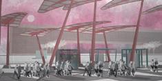
in this city, but insufficient residents support the spaces. The city could not display users’ minds in the urban area. So this design chose the bus stops on the sites, trying to put the primary users’ minds together, performing this urban information, and building a series of popup activities in each urban zone. Finally, it will become a mega-system infrastructure.
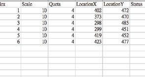
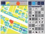
The public used the GUI ( Graphical User Interface ) to build the real-time database. According to the data, we put the new common spaces and programs into the empty spaces in the urban, and new input data in real-time will change them. The bus station is an infrastructure including an urban internet, so the design chooses this subject to do the urban experiment. This project also imaged the future communication between the urban spaces and the users.
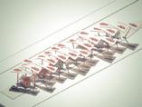
This thesis design started with urban research and theories and focused on a bus line across the city. And then, it tried to figure out an idea for the pop-up design to fit in an infrastructure. Besides, this project utilized the Processing script to create GUI, exporting related results to the Arduino model for displaying the design concept.
Taiwan 20 Selected Thesis Design Exhibition, Selected Award Re-thinking the Future Sustainability Award, First Award Cross-Straits Architecture Competition for Graduate Projects Award, Dept.Recommended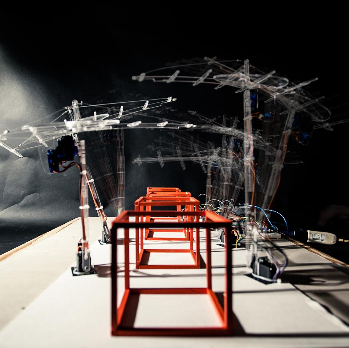
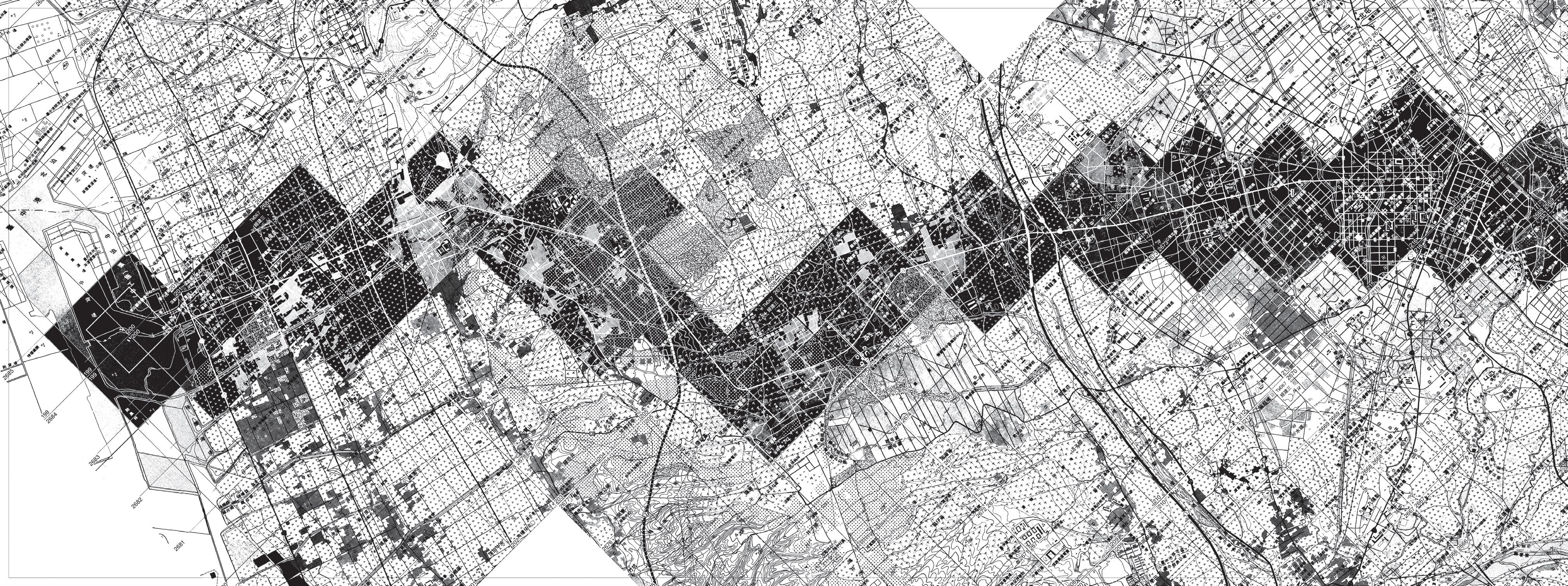
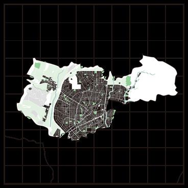
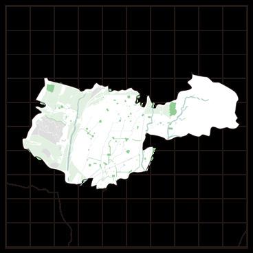
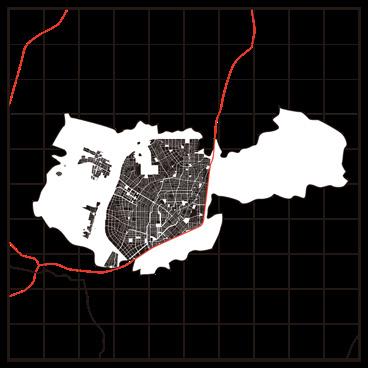
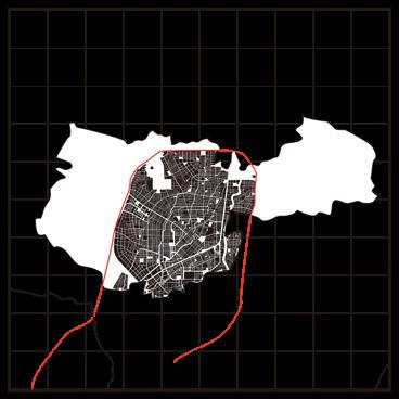
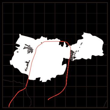
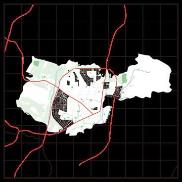
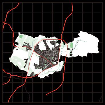
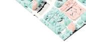
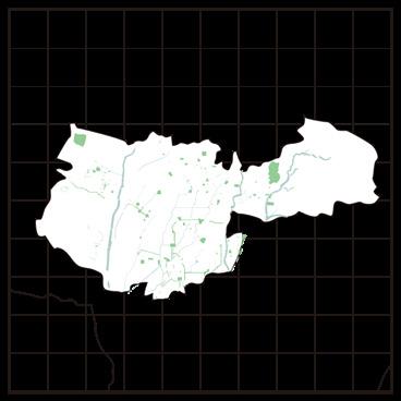 Taichung Downtown Map Without Buildings Occupancies
Front Part of The Railway Station Inside Part of The Highway outside Part of The Highway
Taichung Downtown Map Without Buildings Occupancies
Front Part of The Railway Station Inside Part of The Highway outside Part of The Highway


 Studio Project/ Tunghai University/ 4th year sem7/ 2014 Advisor: Tien Ling tienling@arch.nycu.edu.tw
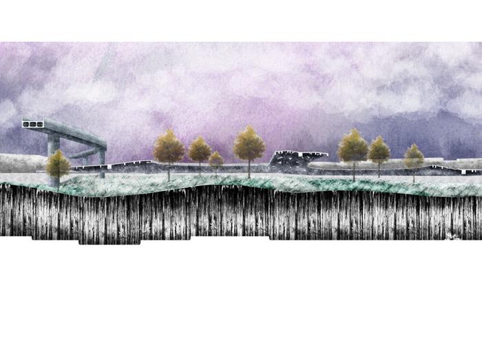
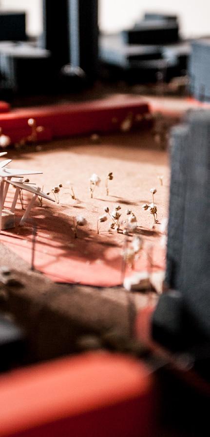
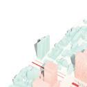
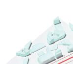
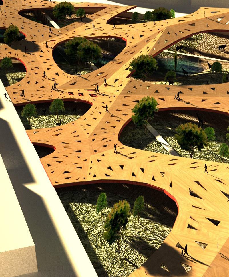
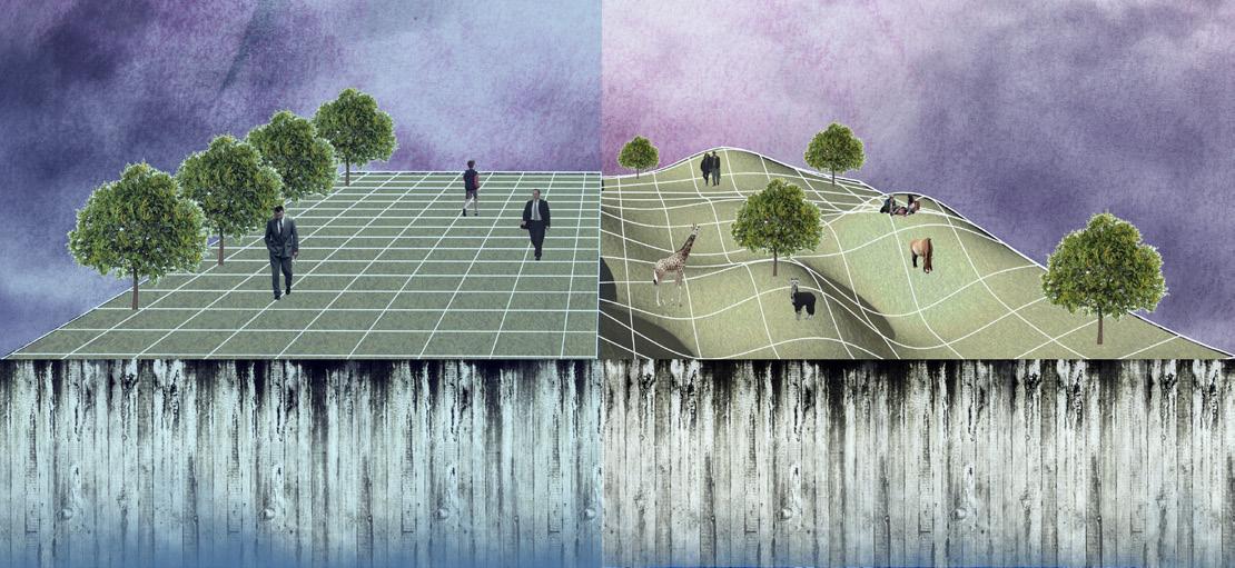
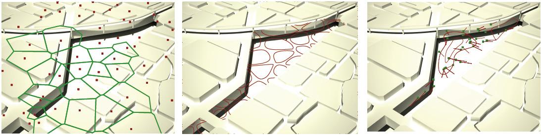
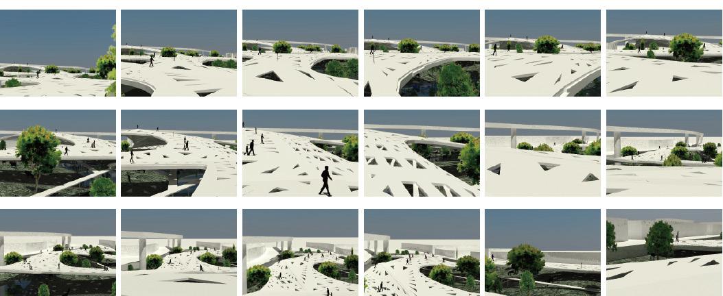
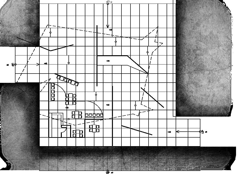
Urban parks usually display a stable module appearance, such as the same distance of trees or pavement patterns. The metropolitan is filled with these kinds of familiar elements and loses the identity of the place. This project tried to break the regular orders, coming out with a parametric-driven design.
This project utilized the bulging surface to intertwine with the original park place. The top or bottom metaphor for the desperate points in the area, and then these points generated the surface. With the different weights of points, they demonstrated on the landform.
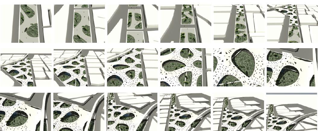
The design had a new chance to reset the program on the generated surface. The bulging surface created the difference in height level. The original height level kept used as walk paths, and other levels made apply in various programs rely on slope grades because of differences in walking velocity. Furthermore, these slope surfaces would create the node spaces and activities.
This project considered the range of bulging surfaces with actual space conditions. For instance, the hills could block the visual connection to transform the linear park into the network node park. The valleys could be artificial ponds as urban flood control infrastructure. Also, they added the elements of landscape and plugin ecosystem in the new network parks.
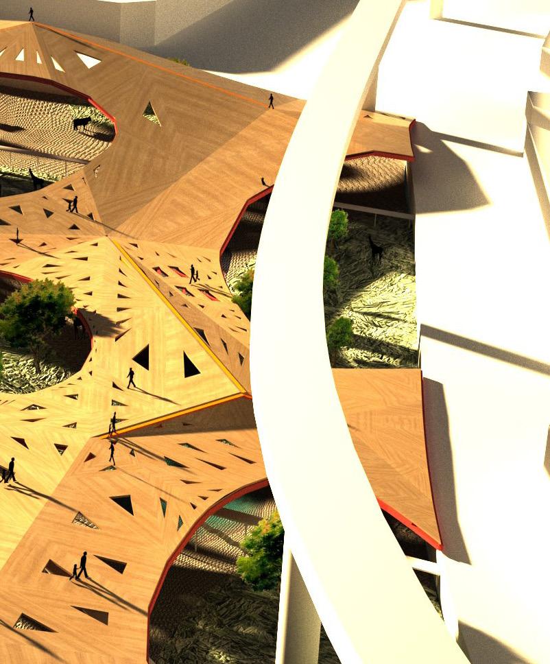
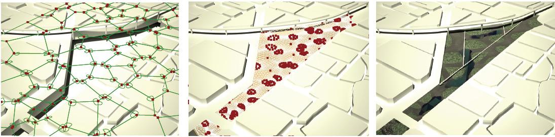
The site has located at the intersection of the greenbelt and the railway. There was an underground entrance of the road nearby. The place was a triangle park enclosed by several traffic lines. However, there were various urban high-speed passing by, and the park showed a slow velocity in this area. The surrounding was a low-density residential zone or undeveloped land. As a result, the site was a large area, but there
were few activities.
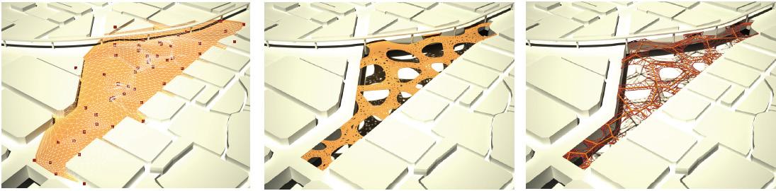
On the other hand, it was close to the railway splitting the connection between both sides. The raised railway would change the relation later, but the design had to respond to the low density of urban space. The project would like to release the human area and recover it as an ecological habitat.
After creating the bulging surface, the design kept the neutral zone (height level unchanged), the compressed space, for human activities. Others were applied for ecological activities. There were two layers, and the ecological layer was a sunken surface ranging from -5m to -15m, setting the pond's level under -10m. The human layer was a bridge network with the scenes of nodes zoo. The animal activities would follow the center of the nodes, and the opening of the bridge would impact the distribution of the plants.
This design utilized the Grasshopper to define the algorithm and parameters. Combined with urban park research and program reorganization, it experimented with an urban landscape strategy in the dynamic urban context.


 Studio Project/ Tunghai University/ 4th year sem8/ 2015 Advisor: Kuan-Fan Chen, SEng fandesign14@gmail.com
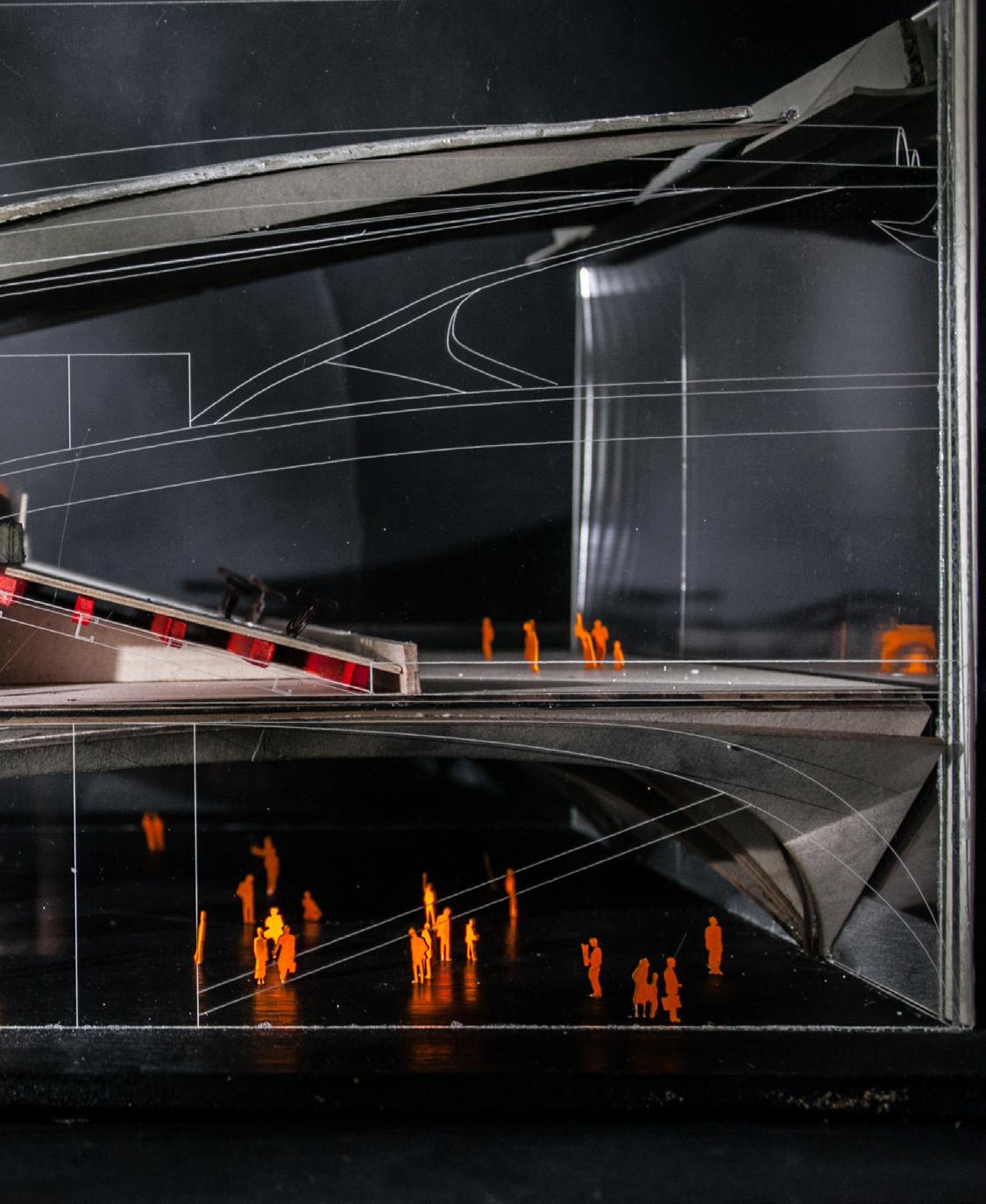
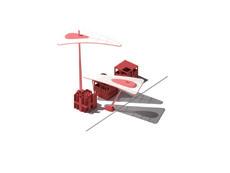
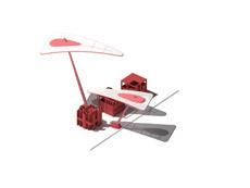
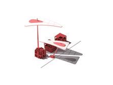
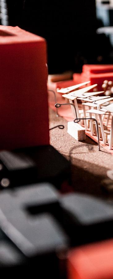
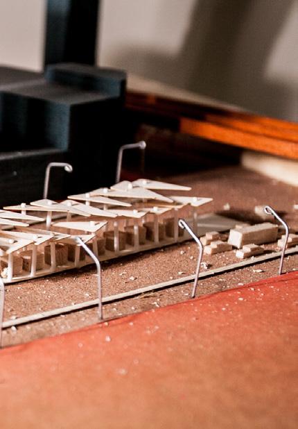
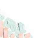
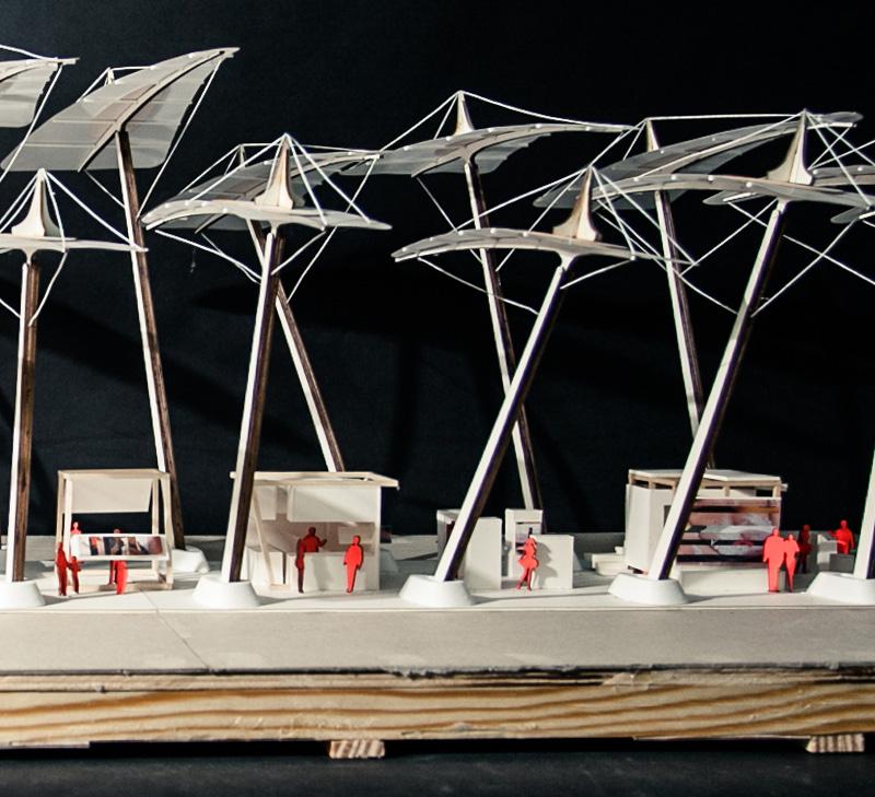
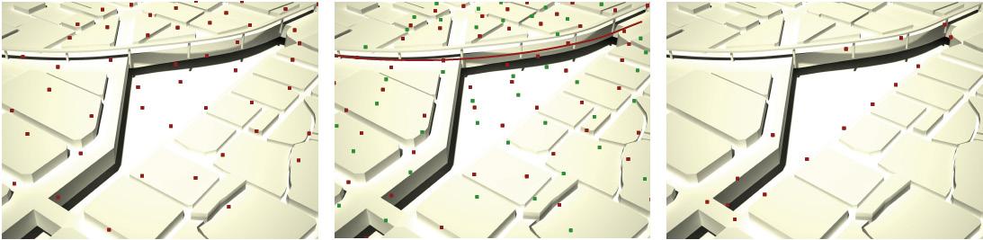
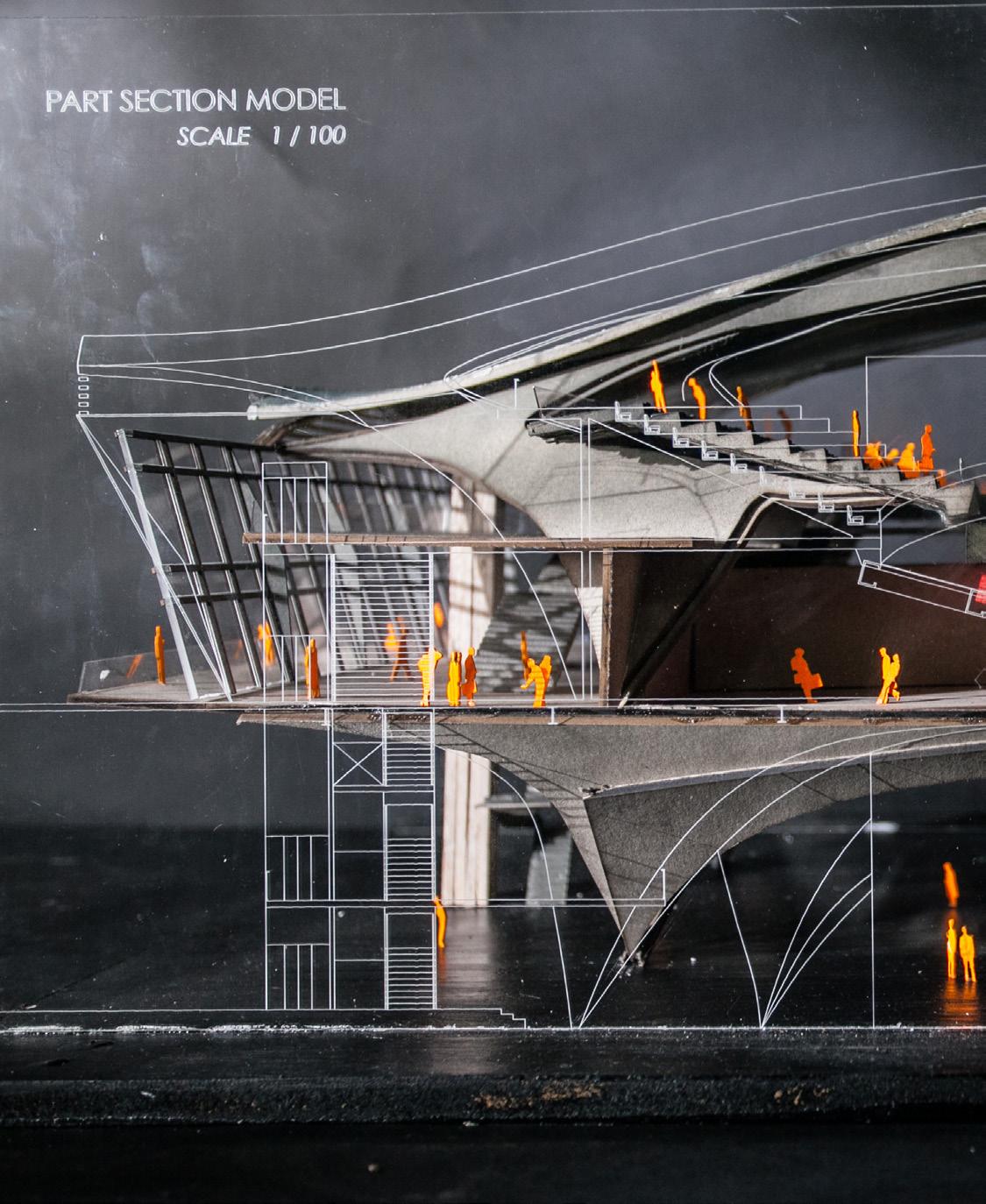
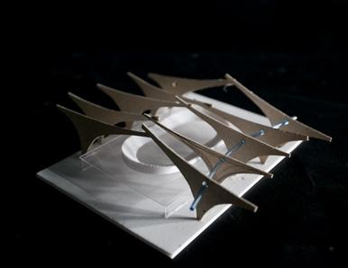
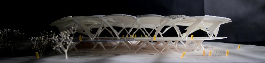
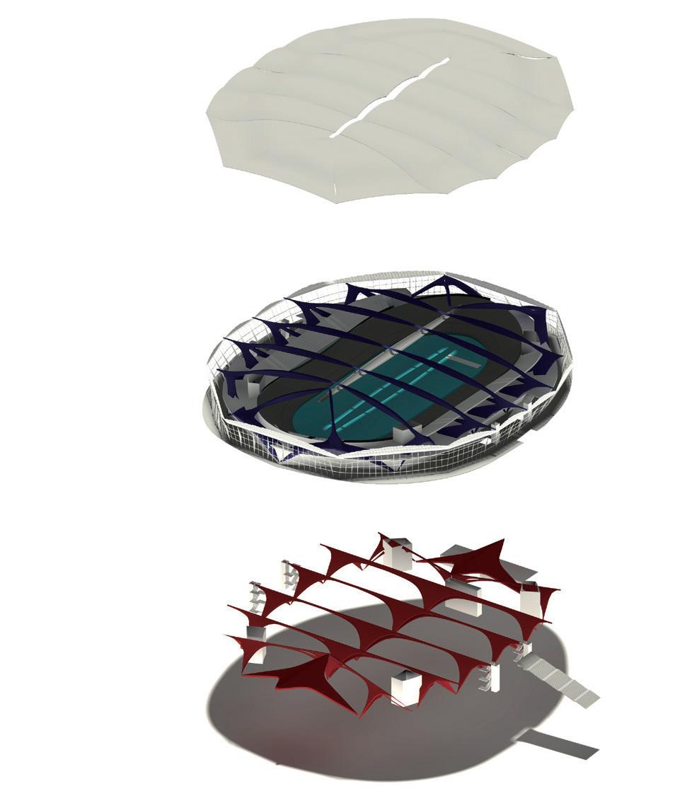
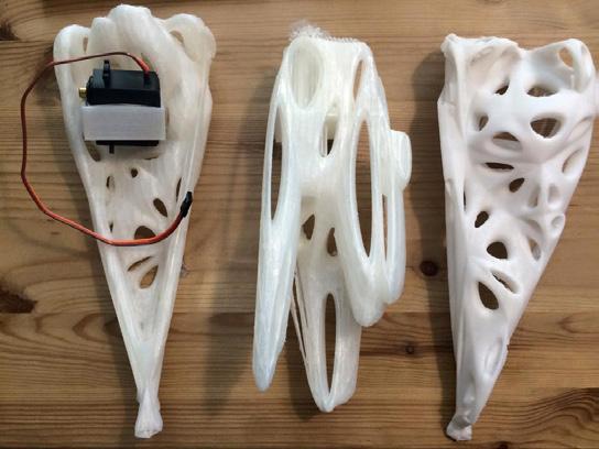
The form of the cycling runway expresses the invisible force behind the surface. The design showed how to use concrete objects to demonstrate invisible physics phenomena. This kind of architectural narrative is the main task in this studio project.
The design realized the cycling race by observing the form of the runway. The runway was different from the field track. In the competition, the rider's weight and high velocity generate the centripetal force on the slope of the runway. Therefore, cycling is a sport about cooperation between humans and bicycles.
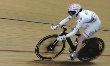
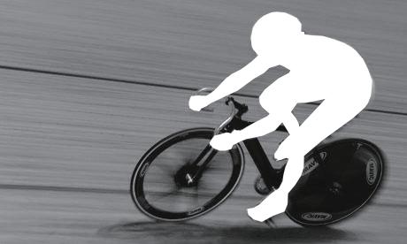
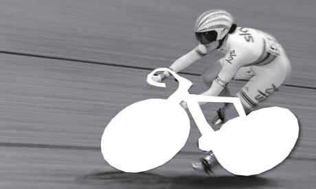
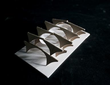
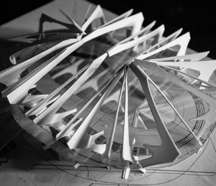
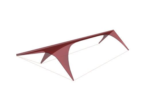
Both can not remove each other, so the design developed the central concept in the structure system, a unit of the tree-hinged arch. The stadium design consisted of pairs of structure units and performed a long-span room for the cycling competition. The stadium would be built in an enclosed arch system to reach the balance of force.
In this project, I used study models and rapid prototyping methods to find suitable structural forms and tried to organize the whole building system in possibility.


Audience Balcony Plan
Entrance Floor Plan
Studio Project/ Tunghai University/ 3th year sem5/ 2013
Advisor: Wen-Liang Kuo made26@yahoo.com
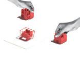
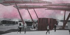
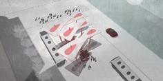
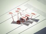
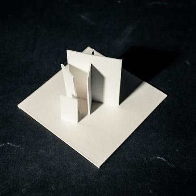
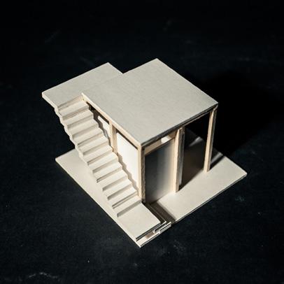
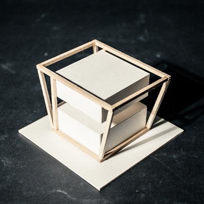
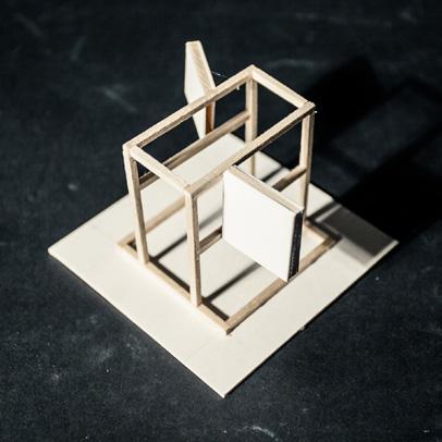
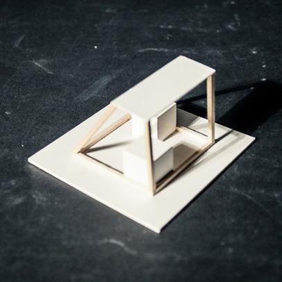
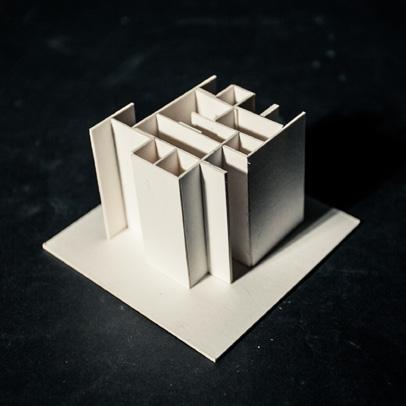
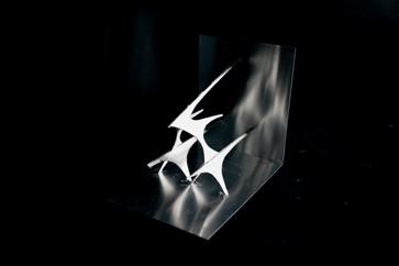
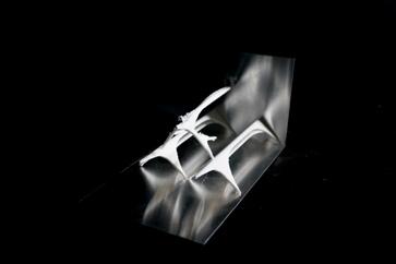
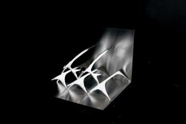
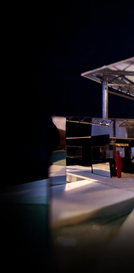
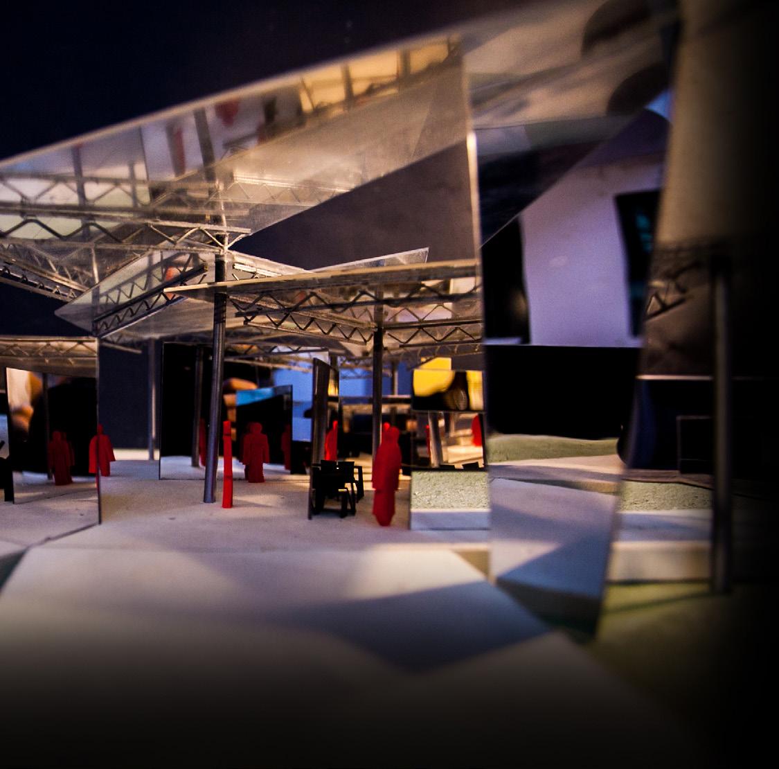
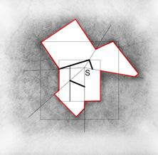
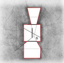
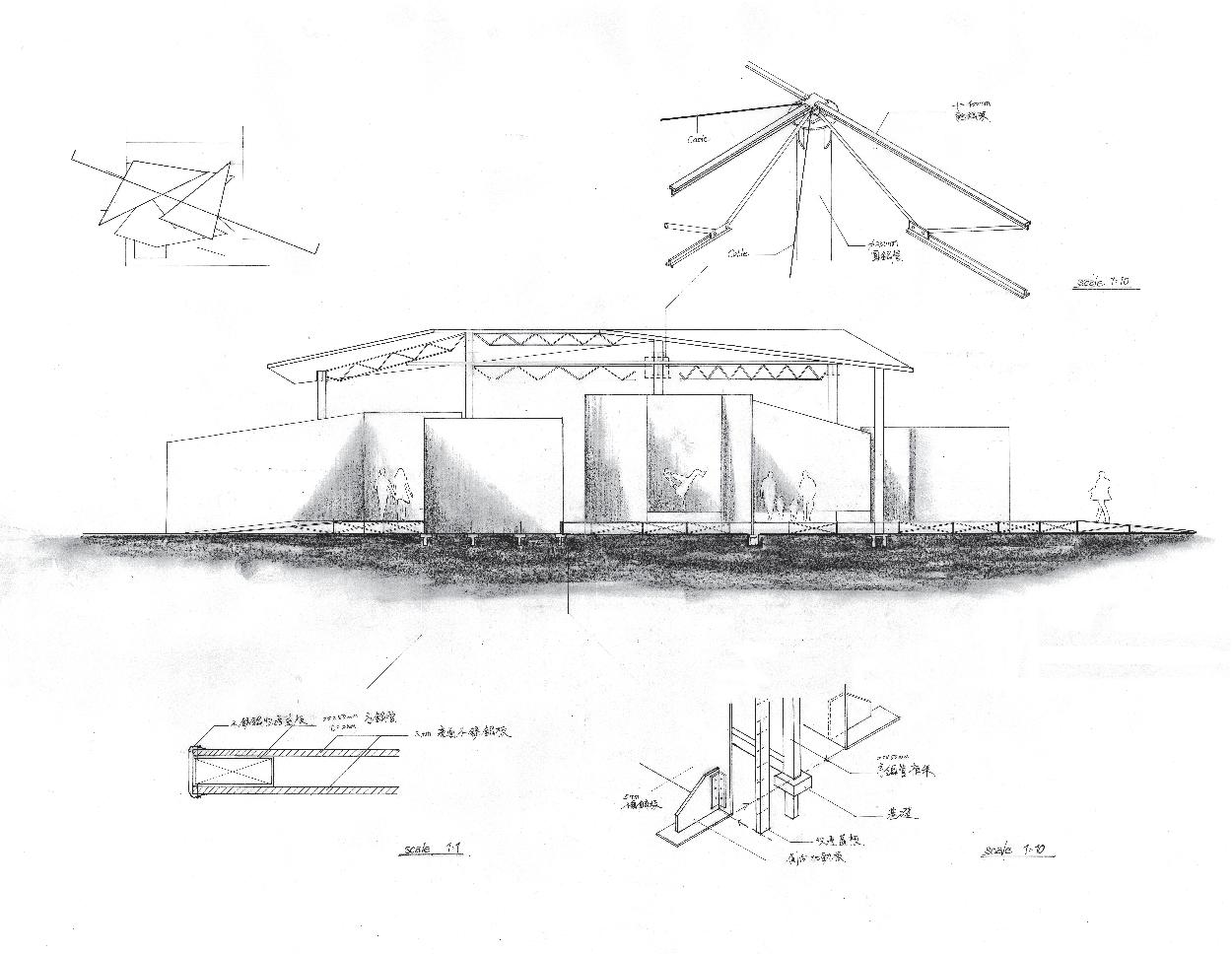
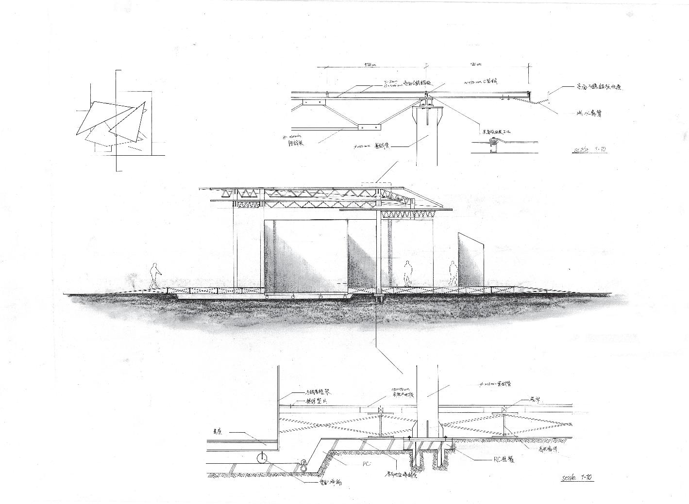
Realizing the elements of architecture defined the place's identity, this studio project researched the reflecting effect between inside and outside by elements interposing the site. This design was a temporary pavilion for International Documentary Festival. It used the walking experience as a promotion method for the festival. People can walk this pavilion from outside to inside and then pass by.
Arrays of columns distinguished the pavilion (inside) and surroundings (outside). In my experiment model, I choose the height of the floor's level, transparent panels, and reflecting panels to study. The reflecting boards could establish the original space order to distinguish between inside and outside, and they reflected the virtual space in the panels compared to the reality pavilion space. Finally, it displayed a unique interposing experience for each visitor.
In reflecting space, the body and the virtual one existed at the same time. The figures were the same size and distance from the panel but in the reversal figure. These figures are reconnected by reflecting and creating the relationship between active and passive.
In this project, I used study models to express the spatial performance and tried to develop possible details drawings for responding to temporary pavilion requirements.

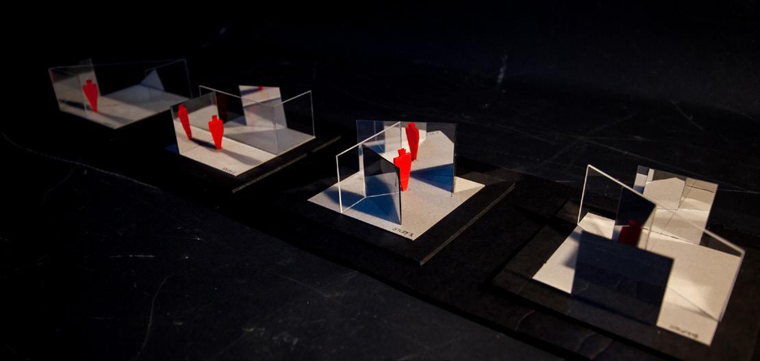 Reflecting Model Studies
Spatial Elements Model Studies
Reflecting Model Studies
Spatial Elements Model Studies


2019-2022
DesignHsinchu Southern Gate Market / Individual Work Hsinchu City, 2020-2021
Building Information: Hsinchu Southern Gate Market Location: Hsinchu, Taiwan
Type: Market Building Construction end: 1954 Structure: brick wall, Steel roof truss, RC framework
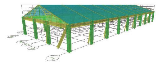
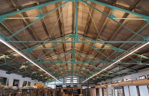
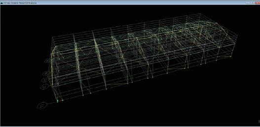
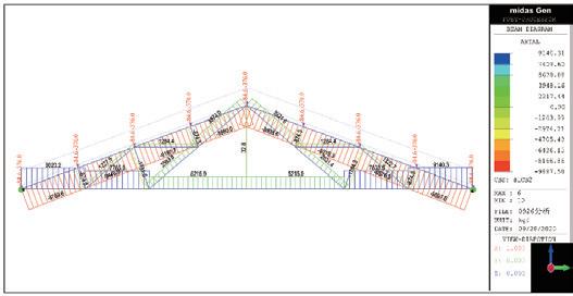
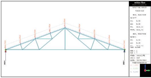
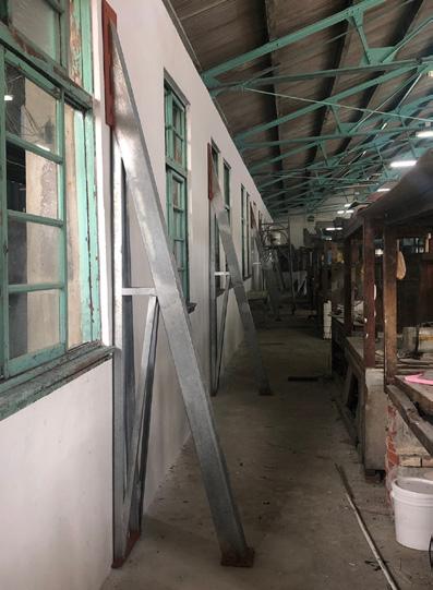
Hsinchu Southern Gate Market is a near 70 years public market building. The main structure is an RC framework and brick walls. The roof structure type is an L-shaped steel fink-truss. Because its structure members were already worse than the original, it seemed concerned about public safety. With the rejuvenating idea, this project presented a suitable seismic rehabilitation design. It could enhance sufficient strength to correspond to the requirement of the structure criteria.
The primary purpose of this project was to retrofit the original structure system. Because the appearance of the building was related to local history, the design offered a proposal that was the minimum influence on the facade to meet the expectation. The common reinforcing methods are enlarging columns or adding buttress walls. However, this case applied steel truss buttress units, and steel framework supports to do the retrofit works. This seismic evaluation (TEASPA, Taiwan Earthquake Assessment for Structures by Pushover Analysis) followed the criteria (NCREE-13-023, National Center for Research on Earthquake Engineering), and the performance of the design reached the requirement of the standard.
I participated in this project's on-site investigation, structure model analysis report, design drawings, and budgeting. Our team completed the design phase in 2020 and the construction phase in 2021.
 Actual Project/ Justin C. H. Shin Structural Engineer & Associates/
Revisor: Chung-Hsien Shih, SEng shih2397697@gmail.com
Hsinchu Southern Gate Market (completed)(2022)
Structure Model in Etabs
Actual Project/ Justin C. H. Shin Structural Engineer & Associates/
Revisor: Chung-Hsien Shih, SEng shih2397697@gmail.com
Hsinchu Southern Gate Market (completed)(2022)
Structure Model in Etabs
Structure Design Drawings
Structure Design Drawings
Foot Details Drawings

2021-2022
Building Information:
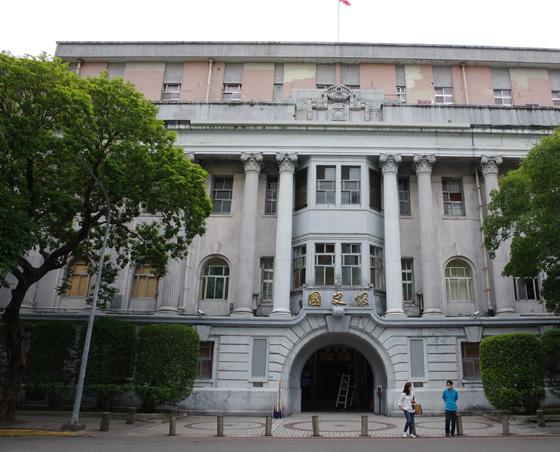
Ministy of Posts and Telecommunications
Location: Taipei, Taiwan
Type: Official Building
Construction end: 1924 (1-3 Floor)
Extension Construction end: 1972 (4 Floor)
Architect: Matsunosuke Moriyama
Structure: brick wall, Steel beam, RC beam & slabs
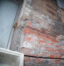
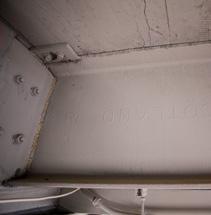
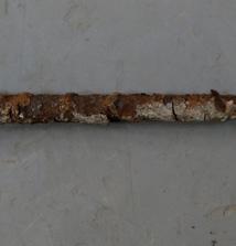
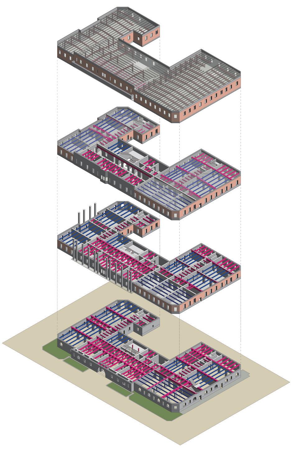
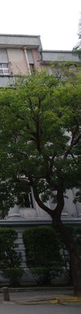
This building was a vital government office in the Japanese colonial period, hosting the posts and communications. After WWII, the Ministry of Transportation and Communication took over this building until 2006. This building was evidence of Taiwan's communication history. Besides, Matsunosuke Moriyama was the architect of this case, the architect of the Taiwan Governor's Office, who was one of the significant architects in the Japanese control period. This case was also his last work before leaving Taiwan. Before the construction began, he had been to Europe and the US to survey the newest tectonic knowledge and materials, such as the highquality steel H-shaped beam made in Scotland and the new style of corrugated rebar made in the US. After the Kanto earthquake (1923) in Japan domestic, this building was designed with the modified structure criteria, and it would be the safest building in the 1920s. During Taipei Air Raid (1945), part of the building was destroyed by bombs. After WWII, there were insufficient rooms in the office; as a result, the 4th-floor extension construction was completed in 1972. These large-span rooms were made up of rebartruss, which was the most effective method in the 1970s. Therefore, this building was evidence of Taiwan's tectonic history for nearly a century.
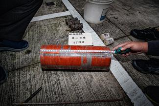
The primary purpose of this project was overall structure evaluation. It examined the current structure system built nearly 100 years with the possible earthquake risk. After that, we advised restoration and retrofit methods for different damaged parts.
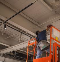

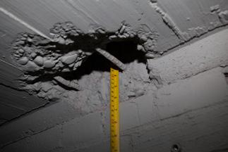
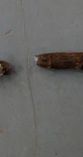
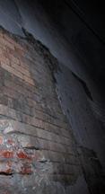
I participated in this project's on-site overall investigation, including detecting rebars, sampling materials, inspecting rust on steel, etc. Meanwhile, comparing the original design drawings and the current ones, I represented the structural model and drawings to evaluate the performance of the structure system.
Sampling
 Ministy of Posts and Telecommunications (Japanese colonial period) / Individual Work Taipei City,
Ministy of Posts and Telecommunications
Layers
Detecting
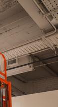
H-Shaped Steel Beam (from
Rebar-Truss (span=26m)
Cracks Inspection
Corrugated Rebar (from the US)
Sampling (Brick)
Ministy of Posts and Telecommunications (Japanese colonial period) / Individual Work Taipei City,
Ministy of Posts and Telecommunications
Layers
Detecting
H-Shaped Steel Beam (from
Rebar-Truss (span=26m)
Cracks Inspection
Corrugated Rebar (from the US)
Sampling (Brick)
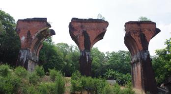
Building Information: Remains of Longteng Bridge
Location: Miaoli, Taiwan
Type: Railway Bridge
Construction end: 1907
Destruction cause: Hsinchu-Taichung earthquake on 21 April 1935
Structure: brickwork arch bridge
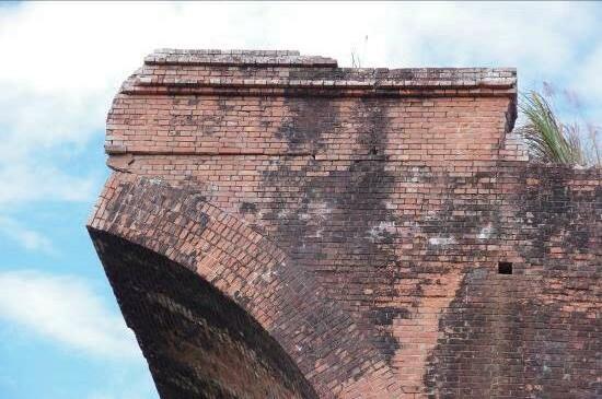
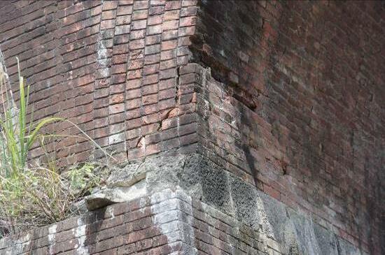
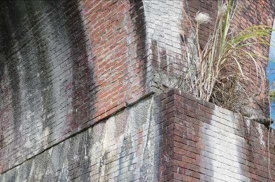
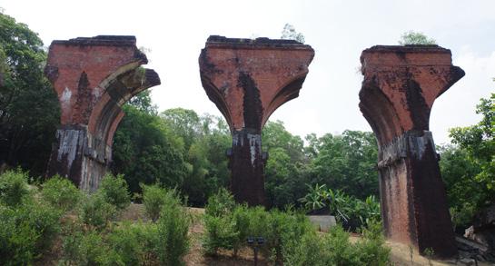
Longteng bridge was a rare brickwork arch bridge in Taiwan that was built in the Japanese colonial period. This part of the railway was the most challenging construction and the highest altitude (402m) in Taiwan's North-South Main Line. Besides, it was also a piece of significant historical evidence about the earthquake in 1935. After that, it changed the North-South Main Line into the new path in the present. In 1999, the Jiji earthquake destroyed the 4th pier, and this remains wrote the earthquake history again.
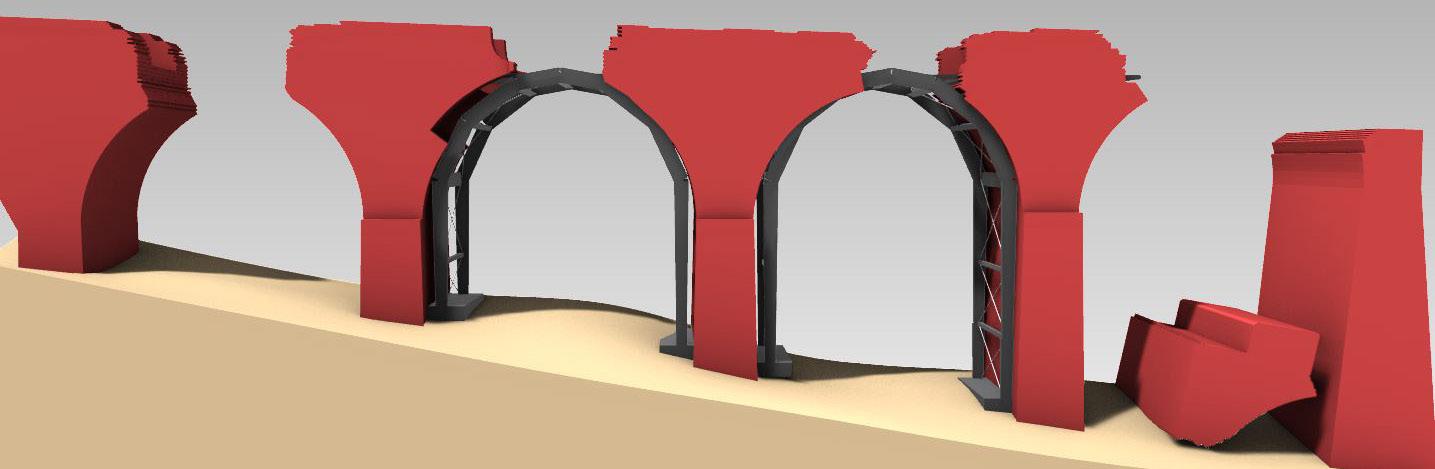
The main task of this project was to offer an emergent action for preventing bridge bodies from falling in later earthquakes. Because it was an unstable arch-type structure after the damage in 1935, it needed to set a retrofit design. Otherwise, it could be destroyed again by earthquakes in the future, such as those happening in 1935 and 1999.
To begin with the design, we examined the damages to the bridge bodies. These pictures showed these cracks and surmise the causes, such as shearing and torsion. This project predicted the possible falling, so we designed a steel framework to resist the impact loads from earthquakes. According to Cultural Heritage Preservation Act, our design should follow the minimum influence on this historical environment. Therefore, this steel framework was an identifiable attachment against the original brickwork. On the other hand, this steel framework was an arch structural form for responding to the stability of the structure system.
I participated in this project's on-site investigation, structure model analysis report, design drawings, and budgeting. The design phase was completed in 2019, but the construction phase began in 2022 due to the materials price dramatically rising in these years.
Remains of Longteng Bridge (2019) Cracks of torsion Displacements of torsion Cracks of shearingDesign Drawings (Longitudinal Section)
Design Drawings (Cross Section) Design Drawings (Details)

//declare dispaly counts int ballCount=60; float[] centerX=new float[ballCount]; float[] centerY=new float[ballCount]; float[] speedX=new float[ballCount]; float[] speedY=new float[ballCount]; float[] scalar=new float[ballCount]; float[] angle=new float[ballCount]; //background setup float k=0; float exponentX=1; float exponentY=1; void setup() { size(1250, 700); frameRate(100); background(0); // original data for (int i=0; i<ballCount; i++) { centerX[i]=random(0, width); centerY[i]=random(0, height); speedX[i]=random(-1.5, 1.5); speedY[i]=random(-1.5, 1.5); scalar[i]=random(50, 100); angle[i]=random(TWO_PI); } }
void draw() {
//renew background and delay effect noStroke(); fill(0, 5); rect(0, 0, width, height); k+=0.1; //back to start situation if (k==1) { k=0; background(0, 25, 30); }
// big ball move for (int i=0; i<ballCount; i++) { centerX[i]+=pow(speedX[i], exponentX); centerY[i]+=pow(speedY[i], exponentY); // combine big ball rule
for (int j = 0; j<ballCount; j++) { stroke(255); strokeWeight(0.01); if (abs(centerX[i]-centerX[j])<150 && abs(centerY[i]centerY[j])<150) { line(centerX[i], centerY[i], centerX[j], centerY[j]); } }
//display big ball ball(centerX[i], centerY[i], scalar[i], angle[i]); // define the edge if (centerX[i]>width) speedX[i] = speedX[i]*-1; if (centerX[i]<0) speedX[i] = speedX[i]*-1; if (centerY[i]>height) speedY[i] = speedY[i]*-1; if (centerY[i]<0) speedY[i] = speedY[i]*-1; //small ball circle moving angle[i]+=0.01; } }
void ball(float ballX, float ballY, float ballScalar, float ballAngle) { //big ball fill(0, 204, 204); ellipse(ballX, ballY, 5, 5); //small ball ellipse(ballX+ballScalar*cos(ballAngle), ballY+ballScalar*sin(ballAngle), 2, 2); ellipse(ballX+ballScalar*cos(ballAngle+ PI), ballY+ballScalar*sin(ballAngle+PI), 2, 2); //balls group connect line stroke(255); strokeWeight(0.01); line(ballX, ballY, ballX+ballScalar*cos(ballAngle), ballY+ballScalar*sin(ballAngle)); line(ballX, ballY, ballX+ballScalar*cos(b allAngle+PI), ballY+ballScalar*sin(ballAngl e+PI)); }
Animation Recording Link: https://youtu.be/R2SXvIRPdFIfloat recScale=8; float ang=0; float d=0.005f; void setup() { size(1000, 1000); frameRate(5); } void draw() { background(0); pushMatrix(); translate(width/2, height/2); rotate(-0.1f*(sin(ang/100))); scale(abs(sin(ang/500))*2+1); for (int i=-width; i<width; i+=10) { for (int j=-width; j<width; j+=10) { ang+=0.0005f; rect(i, j, abs(recScale*sin(ang+(i+2*j)*d)), abs(recScale*sin(ang+(i+2*j)*d))); rect(i, j, abs(recScale*sin(ang+(i-2*j)*d)), abs(recScale*sin(ang+(i-2*j)*d))); stroke(255); strokeWeight(0.1f); line(i, -height, i, height); line(-width, i, width, i); } } popMatrix(); }
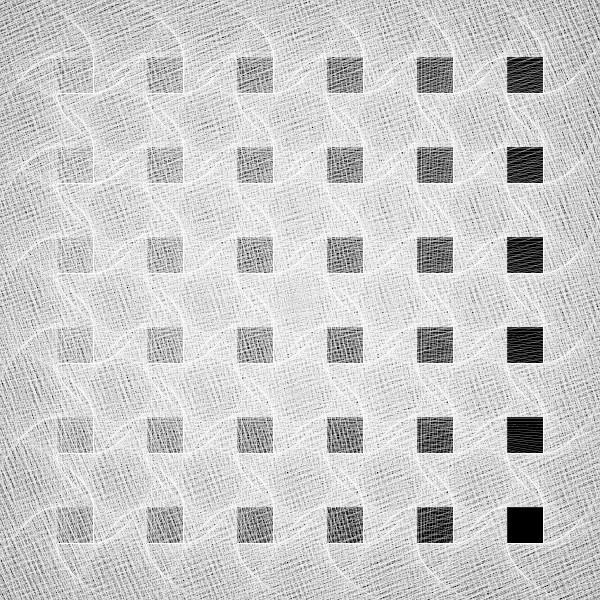
void setup(){ size(600,600); smooth(); background(0); } void draw(){ for(int i=0;i<1800;i+=300){ for(int j=0;j<1800;j+=300){ pattern(i,j); } } noLoop(); }
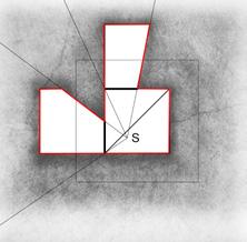
void pattern(int x,int y){ float k=0; float s=120; float q=500; float a=0.5; float b=10; pushMatrix(); scale(0.3); translate(x,y); stroke(255); strokeWeight(0.5); for(float i=k; i<(q-s)/2; i=i+0.5){ line((q-s)/2-b*i,(q-s)/2+a*i*i, (q-s)/2+a*i*i,(q+s)/2+b*i); line((q-s)/2+a*i*i,(q+s)/2+b*i, (q+s)/2+b*i ,(q+s)/2-a*i*i); line((q+s)/2+b*i,(q+s)/2-a*i*i, (q+s)/2-a*i*i,(q-s)/2-b*i); line((q+s)/2-a*i*i,(q-s)/2-b*i, (q-s)/2-b*i,(q-s)/2+a*i*i); line((q-s)/2,(q-s)/2,s,s); line(0); } popMatrix(); }

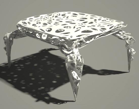
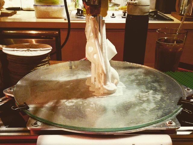
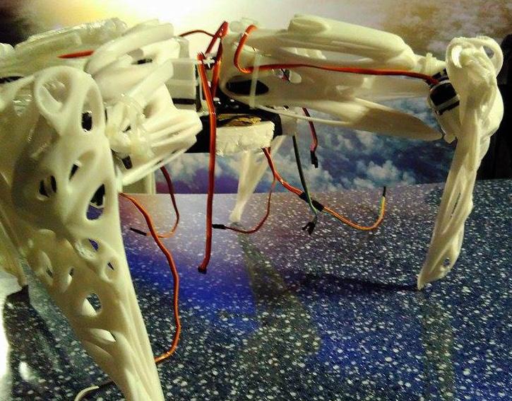

 Project 04 ParaBeast (co-working)
Grasshopper + Arduino + 3D printing / 2015 Taipei Maker Faire
Project 05 ParaLamp
Grasshopper + 3D printing /
Project 04 ParaBeast (co-working)
Grasshopper + Arduino + 3D printing / 2015 Taipei Maker Faire
Project 05 ParaLamp
Grasshopper + 3D printing /