466 ENGINE <1992> - Piston and Connecting Rod
11 C-96
REMOVAL SERVICE POINTS aA0 CONNECTING ROD CAP REMOVAL number
(1) Mark the cylinder number on the side of the connecting rod big end for correct reassembly. (2) Keep the removed connecting rods, caps, and bearings in order according to the cylinder number.
cJB0 PISTON PIN REMOVAL
‘iston pin setting 001 MIT216941
Item No. Part No. 1 z 4 i i 9 :‘:
8
11
Description
MIT310134 MIT310136 MIT310137 MIT310138 MIT310139 MIT310140 MIT310141 MIT310142 MIT48143 2 16943 10396
Base Piston Support Connecting Rod Connecting Rod Connecting Rod Piston Support Connecting Rod Piston Support Press Pin Stop Screw Nut
Guide Pin Guide Pin Guide Pin Guide Pin
(1) Remove the stop screw from the base. (2) Select the correct piston support for your application (See above). Fit the piston support onto the base. Place the base on press support blocks.
7EN042E
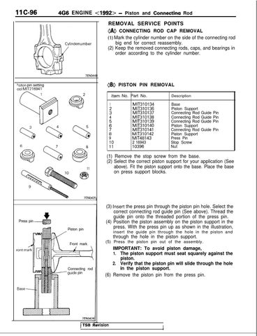
Press pin
(3) Insert the press pin through the piston pin hole. Select the correct connecting rod guide pin (See above). Thread the guide pin onto the threaded portion of the press pin. (4) Position the piston assembly on the piston support in the press. With the press pin up as shown in the illustration,
“‘.q.:::::::::::: .: ‘.:.:.y,:, --is Piston pin
insert the guide pin through the hole in the piston and
through the hole in the piston support. (5) Press the piston pin out of the assembly.
Front mark
Connecting w /guide pin
rod
IMPORTANT: To avoid piston damage, 1. The piston support must seat squarely against the piston. 2. Verify that the piston pin will slide through the hole in the piston support. (6) Remove the piston pin from the press pin.
7EN042fI
vision
I