


FOSHAN HUALU AUTOMATIC CONTROLS LIMITED (China) No.59 & 61, Wenhua Nan Road, Chancheng District Foshan, Guangdong, China Sales & Manufacturing Tel: +86 757 8383 1558 Fax: +86 757 8383 1218 RIMSA SAGINOMIYA, S.A. DE C.V. Danfoss(Mexico) Saginomiya Sp. z o.o. (Poland) ul. Chrzanowska 5, 05-825 Grodzisk Mazowiecki, Poland Manufacturing Tel : +48 22 7550 500 Fax: +48 22 7550 505 SAGINOMIYA EUROPE Sp. z o.o. (Poland) Aleje Jerozolimskie 212 02-486 Warsaw, Poland Sales Tel: +48 22 101 30 00 Fax: +48 22 101 30 01 SAGINOMIYA AMERICA, INC. (USA) S aginomiya ( T hailand) Co , Ltd ( T hailand) 159 Serm-mit Tower 19 th Fl., Room No.1903/1 Sukhumvit 21 Rd., Klongtoey-Nua Wattana, Bangkok 10110, Thailand Sales & Manufacturing Tel: +662 260 8364 Fax: +662 260 8366 Shinjyuku Garden Tower 22F 8-2, Okubo 3-chome, Sinjyuku-ku Tokyo, 169-0072 Japan Tel : +81 3 6205 9123 Fax : +81 3 6205 9125 E-mail: inter@saginomiya.co.jp OVERSEAS NETWORK Headquarters
Tokorozawa
Plant
Yonezawa
Production Department
Sayama
Plant Correo: xbombas@gmail.com Telefono: 55 5378 7190
1 AUTOMATIC CONTROLS Catalog-edition-T ■ REFERENCE INFORMATION ■ APPROVAL STANDARD LIST ■ PRESSURE CONTROLS ■ TEMPERATURE & HUMIDITY CONTROLS ■ PRESSURE & TEMPERATURE CONTROLS INFORMATION ■ EXPANSION VALVES ■ SOLENOID VALVES & CONTROL VALVES ■ OTHER VALVES ■ OTHER CONTROL EQUIPMENT This condensed catalog-T is a revised edition of catalog-S Correo: xbombas@gmail.com Telefono: 55 5378 7190
CONVERSION
SATURATED
APPROVAL
PRESSURE CONTROLS
SMALL PRESSURE CONTROLS
ACB &
SMALL PRESSURE CONTROLS
LTB, ETB,
SINGLE FUNCTION PRESSURE
SNS &
DUAL PRESSURE CONTROLS
SINGLE FUNCTION PRESSURE
SYS
DUAL PRESSURE CONTROLS
DYS
PRESSURE CONTROLS WITH NARROW
FNS &
OIL PROTECTION CONTROLS
DIFFERENTIAL PRESSURE
WNS &
DIGITAL PRESSURE CONTROLS
CFE
PRESSURE SENSORS
NSK & XSK
TEMPERATURE & HUMIDITY CONTROLS
TEMPERATURE CONTROLS
LWS, FWS, RWS & EWS
CONTENTS
PROPORTIONAL TEMPERATURE CONTROLS
Type PWS
ROOM THERMOSTATS
Type ARS
ROOM THERMOSTATS
Type WRS
ROOM HUMIDISTATS
Type AHS
DIGITAL THERMOSTATS & DIGITAL HUMIDISTATS
Type ALE & BLE
DIGITAL THERMOSTATS
Type TNE
TEMPERATURE CONTROLS 31–32 Type TNS, CNS & INS
TEMPERATURE CONTROLS
Type ALS & BLS
35–36
39–42
PRESSURE &TEMPERATURE CONTROLS INFORMATION
CONNECTION & ACCESSORIES
DRIP PROOF & WATER PROOF CONTROLS
Series NS–W & NS–P
EXPANSION VALVES
45–47
48–53
GENERAL INFORMATION 55–56
EXPANSION VALVES 57
Type ARX
EXPANSION VALVES 58–60
Type QCX & RCX
EXPANSION VALVES
61–63 Type SCX EXPANSION VALVES 64 Type BHX EXPANSION VALVES 65–66 Type ATX (R410A) EXPANSION VALVES
67–68 Type ATX EXPANSION VALVES 69–70 Type AEX
ELECTRONIC EXPANSION VALVES
Type UKV, VKV & AKV ELECTRONIC EXPANSION VALVES
Type UKV–F
1 REFERENCE INFORMATION
TABLES ・・・・・・・・・・・・・・・・・・・・・ 1–3
VAPOUR PRESSURE CURVE 4 APPLICATION EXAMPLES 5–6 APPROVAL STANDARD LIST
STANDARD LIST 7
9–10 Type
LCB
11–12 Type
HTB & FTB
CONTROLS 13–14 Type
HNS
15–16 Type DNS
CONTROLS ・・・・・・・・ 17 Type
18 Type
DIFFERENTIAL・・ 19–20 Type
ANS
・・・・・・・・・・・・・・ 21–22 Type ONS
CONTROLS 23 Type
YNS
・・・・・・・・・・・・・・・ 24 Type
25–27 Type
・・・・・・・・・・・・・・・・ 29–30 Type
33
34
・・・・・・・・・・・・・・・・・・・
37
38
・・・
43
・・・・・・・・・・・・・
・・・・・・
・・・・・・・・・・・・・・・・・・・・
・・・・・・・・・・・・・・・・・・・・
・・・・・・・・・・・ 71–73
74
A ACB 9–10 ACV ・・・・・・・・・ 99 ADV 111 AEX 69–70 AHS ・・・・・・・・・ 38 AKM 122 AKV 71–73 ALE ・・・・・・・ 39–42 ALS 33 ANS ・・・・・・・ 19–20 ANS–P 48–53 ANS–W 48–53 ARS ・・・・・・・ 35–36 ARX 57 ATX 67–68 ATX (R410A) ・・ 65–66 AWR 101–102 B BCV 99 BHX 64 BKM 122 BLE ・・・・・・・ 39–42 BLS 33 BPV 86 C CAV 123–124 CCB 125–127 CFE ・・・・・・・・・ 24 CNS 31–32 CNS–P ・・・・・・ 48–53 CNS–W 48–53 CRV 123–124 CWR ・・・・・・ 101–102 D DNS 15–16 DNS–P ・・・・・・ 48–53 DNS –W 48–53 DPR 107–108 DYS 18 E EGK 93–84 ELK ・・・ 115,123–124 EPR 105–106 ETB 11–12 EWS ・・・・・・・ 29–30 F FNS 19–20 FNS–P ・・・・・・ 48–53 FNS–W 48–53 FQS ・・・・・・・・・116 FTB 11–12 FWS 29–30 G GWR 101–102 H HBL ・・・・・・・・・128 HEV 123–124 HNS 13–14 HNS –W 48–53 HPR 109–110 HPV 125–127 HSK ・・・・・・ 125–127 HTB 11–12 HWR 103–104 I INS 31–32 INS–W 48–53 IEV ・・・・・・・・・・ 87 J JKV・・・・・・・ 125–127 L LCB 9–10 LNE ・・・・・・・・・ 75 LTB 11–12 LWS 29–30 M MDP 118 MJV 91–92 MWR 101–102 TYPE NUMBER INDEX Correo: xbombas@gmail.com Telefono: 55 5378 7190
PULSE CONVERTERS
Type LNE
SOLENOID VALVES & CONTROL VALVES
SOLENOID VALVES FOR REFRIGERANT
Type TEV & VPV
SOLENOID VALVES FOR REFRIGERANT
Type SEV
SOLENOID VALVES FOR REFRIGERANT
Type RPV
SOLENOID VALVES FOR REFRIGERANT
REV & UEV
SOLENOID VALVES FOR WATER
WEV
BI-FLOW SOLENOID VALVES
BPV
3-WAY SOLENOID VALVES
IEV
4-WAY REVERSING VALVES
STF
MOTORIZED BALL VALVES
Type MJV
DAMPER & VALVE MOTOR ACTUATORS 93–94
EGK & WGK
2-WAY & 3-WAY CONTROL VALVES
Type NVK
OTHER VALVES
CHECK VALVES
Type ACV & BCV
95–97
PRESSURE REGULATING VALVES 107–108
Type SPR & DPR
PRESSURE REGULATING VALVES
Type HPR
109–110
DIAPHRAGM TYPE STOP VALVES 111
Type ADV
BELLOWS TYPE STOP VALVES 112–113
Type NBV
OTHER CONTROL EQUIPMENT
FLOW SENSORS 115
Type ELK
FLOW SWITCHES 116 Type FQS
DRAIN PUMPS
Type SDP
117
DRAIN PUMPS 118 Type MDP
CONDENSER FAN SPEED CONTROLLERS
Type RGE
119–120
CONDENSER FAN SPEED CONTROLLERS 121 Type XGE
TEMPERATURE RECORDERS
AKM & BKM
CONTROL APPLIANCES FOR HOT WATER SUPPLY UNITS
CRV, VSV, WSV, HEV, XJV, QJV, TCV, CAV, ELK
REFRIGERANT APPLICATIONS
CCB, HSK, HPV, UKV–J & JKV
123–124
125–127
PRESSURE ACTUATED WATER REGULATING VALVES
100 Type VWR
PRESSURE ACTUATED WATER REGULATING VALVES 101–102 Type CWR, AWR, GWR, MWR & SWR
HBL & WSL
CONTROLS & VALVES
103–104 Type OWR, HWR & XWR
TEMPERATURE ACTUATED WATER REGULATING VALVES
PRESSURE REGULATING VALVES 105–106 Type EPR
2
75
77
78–79
・・・・・・・・ 80–81
82–84 Type
85 Type
・・・・・・・・・・・・・・・・・ 86 Type
87 Type
・・・・・・・・・・・・・・・・ 88–90 Type
91–92
Type
・・・・・・・・・・・
99
・・・・・・
・・・
・・・・・・・・・・・
・・・・・・・・・・・・・・・・・・・・・・・・・・
・・・・・・
122 Type
・・・
Type
CO2
・・・・・・・・・・
Type
BELLOWS 128 Type
OTHER
・・・・・・・・・・・・・・・・ 129 Type RKV & BI-METAL (No. 03, 05 & 24) N NBV 112–113 NSK ・・・・・・・ 25–27 NVK 95–97 O ONS ・・・・・・・ 21–22 ONS –W 48–53 OWR 103–104 P PKV 129 PWS ・・・・・・・・・ 34 Q QCX 58–60 QJV ・・・・・・ 123–124 R RCX 58–60 REV ・・・・・・・ 82–84 RGE 119–120 RKV 129 RPV 80–81 RWS 29–30 S SCX 61–63 SDP ・・・・・・・・・117 SEV 78–79 SNS 13–14 SNS–P ・・・・・・ 48–53 SNS –W 48–53 SPR 107–108 STF ・・・・・・・・ 88–90 SWR 101–102 SYS ・・・・・・・・・ 17 T TCV 123–124 TEV・・・・・・・・・・ 77 TNE 43 TNS 31–32 TNS–P ・・・・・・ 48–53 TNS –W 48–53 U UEV 82–84 UKV 71–73 UKV–F 74 UKV–J ・・・・・ 125–127 V VKV 71–73 VPV・・・・・・・・・・ 77 VSV 123–124 VWR 100 W WEV 85 WGK ・・・・・・・ 93–94 WNS 23 WNS –W 48–53 WRS ・・・・・・・・・ 37 WSL 128 WSV 123–124 X XGE 121 XJV 123–124 XSK 25–27 XWR 103–104 Y YNS 23 YNS-W ・・・・・・ 48–53 No.03 129 No.05 ・・・・・・・・129 No.24 129 Correo: xbombas@gmail.com Telefono: 55 5378 7190
101.1 150 238.0 95.6 140 220.0 90.0 130 202.0 84.4 120 184.0 78.9 110 166.0 73.3 100 148.0
67.8 90 130.0
62.2 80 112.0 56.7 70 94.0 51.1 60 76.0 45.6 50 58.0 45.0 49 56.2 44.4 48 54.4 43.8 47 52.6 43.3 46 50.8 42.8 45 49.0
42.2 44 47.2 41.7 43 45.4 41.1 42 43.6 40.6 41 41.8 40.0 40 40.0
39.4 39 38.2 38.9 38 36.4 38.3 37 34.6 37.8 36 32.8
°C
37.2 35 31.0
36.7 34 29.2 36.1 33 27.4 35.6 32 25.6 35.0 31 23.8 34.4 30 22.0 33.9 29 20.2 33.3 28 18.4 32.8 27 16.6 32.2 26 14.8 31.7 25 13.0 31.1 24 11.2 30.6 23 9.4 30.0 22 7.6 29.4 21 5.8 28.9 20 4.0 28.3 19 2.2 27.8 18 0.4 27.2 17 1.4 26.7 16 3.2 26.1 15 5.0 25.6 14 6.8 25.0 13 8.6 24.4 12 10.4 23.9 11 12.2
°C
°F 23.3 10 14.0 22.8 9 15.8 22.2 8 17.6 21.7 7 19.4 21.1 6 21.2 20.6 5 23.0 20.0 4 24.8 19.4 3 26.6 18.9 2 28.4 18.3 1 30.2 17.8 0 32.0 17.2 1 33.8 16.7 2 35.6 16.1 3 37.4 15.6 4 39.2 15.0 5 41.0 14.4 6 42.8 13.9 7 44.6 13.3 8 46.4 12.8 9 48.2 12.2 10 50.0 11.7 11 51.8 11.1 12 53.6 10.6 13 55.4 10.0 14 57.2
°C
°F
9.4 15 59.0 8.9 16 60.8 8.3 17 62.6 7.8 18 64.4 7.2 19 66.2 6.7 20 68.0 6.1 21 69.8 5.6 22 71.6 5.0 23 73.4 4.4 24 75.2 3.9 25 77.0 3.3 26 78.8 2.8 27 80.6 2.2 28 82.4 1.7 29 84.2 1.1 30 86.0 0.6 31 87.8 0.0 32 89.6 0.6 33 91.4 1.1 34 93.2 1.7 35 95.0 2.2 36 96.8 2.8 37 98.6 3.3 38 100.4 3.9 39 102.2
°C
°F
4.4 40 104.0 5.0 41 105.8 5.6 42 107.6 6.1 43 109.4
6.7 44 111.2 7.2 45 113.0
7.8 46 114.8 8.3 47 116.6 8.9 48 118.4 9.4 49 120.2 10.0 50 122.0 15.6 60 140.0 21.1 70 158.0 26.7 80 176.0 32.2 90 194.0 37.8 100 212.0 43.3 110 230.0 48.9 120 248.0 54.4 130 266.0 60.0 140 284.0 65.6 150 302.0 71.1 160 320.0 76.7 170 338.0 82.2 180 356.0 87.8 190 374.0
1 REFERENCE INFORMATION 1. CONVERSION TABLES 1) Temperature conversion table (°C °F) The figures in the center column show the temperature to be converted. The figures on the left show conversion from Fahrenheit to Centigrade and the figures on the right from Centigrade to Fahrenheit. Example : Temperature conversion formula : °C=5/9 (°F 32) °F=9/5×°C+32 5°C→41.0°F 15.0°C←5°F °C °F 15.0 5 41.0 °C °F
°F
Correo: xbombas@gmail.com Telefono: 55 5378 7190
This
°C
°F
0.056 0.1 0.18
0.111 0.2 0.36
0.278 0.5 0.90
0.56 1 1.8
1.11 2 3.6 1.67 3 5.4 2.22 4 7.2 2.78 5 9.0
°C
°F
3.33 6 10.8 3.89 7 12.6 4.44 8 14.4 5.00 9 16.2 5.56 10 18.0 6.11 11 19.8 6.67 12 21.6 8.33 15 27.0
3) Pressure conversion table (kgf/cm2 MPa)
is
to a 5°C
The figures in the center column
the figures
Example
1 MPa
the
be converted.
figures on the left show conversion from MPa to kgf/cm2
the right from kgf/cm2 to MPa.
10.1972kgf/cm2, 1kgf/cm2
kgf/cm2 MPa
0 0 0
1.01972 0.1 0.009806
2.03944 0.2 0.019613
3.05916 0.3 0.029420
4.07888 0.4 0.039226
5.09860 0.5 0.049033
6.11832 0.6 0.058839
7.13804 0.7 0.068646
8.15776 0.8 0.078453
9.17748 0.9 0.088259
10.1972 1 0.09807
20.3944 2 0.19613
30.5916 3 0.29420
40.7888 4 0.39227
50.9860 5 0.49033
61.1832 6 0.58840
71.3804 7 0.68647
81.5776 8 0.78453
91.7748 9 0.88260
101.972 10 0.98066
112.169 11 1.07873
122.366 12 1.17680
132.563 13 1.27486
142.760 14 1.37293
152.958 15 1.47100
163.155 16 1.56906
173.352 17 1.66713
183.549 18 1.76520
193.746 19 1.96133
203.944 20 1.96133
kgf/cm2 MPa
MPa
214.141 21 2.05940 224.338 22 2.15746 234.535 23 2.25553 244.732 24 2.35360 254.930 25 2.45166 265.127 26 2.54973 275.324 27 2.64780 285.521 28 2.74586 295.718 29 2.84393 305.916 30 2.94199 316.113 31 3.04006 326.310 32 3.18313 336.507 33 3.23619 346.704 34 3.33426
356.902 35 3.43233 367.099 36 3.53039 377.296 37 3.62846 387.493 38 3.72653 397.690 39 3.82459 407.888 40 3.92266 418.085 41 4.02073 428.282 42 4.11879 438.479 43 4.21686 448.676 44 4.31493 458.874 45 4.41299 469.071 46 4.51106 479.268 47 4.60913 489.465 48 4.70719 499.662 49 4.80526 509.860 50 4.90332
kgf/cm2
MPa 520.057 51 5.00139 530.254 52 5.09946 540.451 53 5.19752 550.648 54 5.29559 560.846 55 5.39366 571.043 56 5.49172 581.240 57 5.58279 591.437 58 5.68786 601.634 59 5.78592 611.832 60 5.88399 622.029 61 5.98206 632.226 62 6.08012 642.423 63 6.17819 652.620 64 6.27626 662.818 65 6.37432 673.015 66 6.47239 683.212 67 6.57046 693.409 68 6.66852 703.606 69 6.76659 713.804 70 6.86465 724.001 71 6.96272 734.198 72 7.06079 744.395 73 7.15885 754.592 74 7.25692 764.790 75 7.35499 774.987 76 7.45305 785.184 77 7.55112
795.381 78 7.64919 805.578 79 7.74725 815.776 80 7.84532
kgf/cm2 MPa 825.973 81 7.94339 836.170 82 8.04145 846.367 83 8.13952 856.564 84 8.23759 866.762 85 8.33565 876.959 86 8.43372 887.156 87 8.53179 897.353 88 8.62985 907.550 89 8.72792 917.748 90 8.82598 927.945 91 8.92405 938.142 92 9.02212 948.339 93 9.12018 958.536 94 9.21825 968.734 95 9.31632 978.931 96 9.41438 989.128 97 9.51245 999.325 98 9.61052 1000.52 99 9.70858 1019.72 100 9.80665 1529.58 150 14.70997 2039.44 200 19.6133 2549.30 250 24.51662 3059.16 300 29.41995 3569.02 350 34.32327 4078.88 400 39.2266 4588.74 450 44.12992 5098.60 500 49.03325
2 2) Temperature difference conversion table (°C °F)
show
pressure to
The
and
on
:
=
=0.09807
table
a comparison table of temperature difference. For example, a 9°F difference (77°F 68°F) corresponds
difference (25°C 20°C).
Correo: xbombas@gmail.com Telefono: 55 5378 7190
kgf/cm2 psi
0.0070 0.1 1.422
0.0141 0.2 2.845
0.0211 0.3 4.267
0.0281 0.4 5.689
0.0352 0.5 7.112
0.0422 0.6 8.534
0.0492 0.7 9.956
0.0562 0.8 11.379
0.0633 0.9 12.801
0.0703 1 14.22
0.1406 2 28.45
0.2109 3 42.67
0.2812 4 56.89 0.3515 5 71.12
0.4218 6 85.34
0.4922 7 99.56
0.5625 8 113.79
0.6328 9 128.01
0.7031 10 142.22
kgf/cm2 psi
0.773 11 156.5
0.844 12 170.8
0.914 13 184.9
0.984 14 199.1
1.055 15 213.4
1.125 16 227.6
1.195 17 241.8
1.266 18 256.0
1.336 19 270.2
1.406 20 284.5
1.477 21 298.7
1.547 22 312.9
1.617 23 327.1
1.687 24 341.4
1.758 25 355.6
1.828 26 369.8
1.898 27 384.0
1.969 28 398.3
2.039 29 412.5
2.109 30 426.7
kgf/cm2 psi
2.180 31 440.9
2.250 32 455.2
2.320 33 469.4
2.390 34 483.6
2.461 35 497.8
2.531 36 512.0
2.601 37 526.3
2.672 38 540.5
2.742 39 554.7
2.812 40 568.9
2.883 41 583.2
2.953 42 597.4
3.023 43 611.6
3.094 44 625.8
3.164 45 640.1
3.234 46 654.3
3.304 47 668.5
3.375 48 682.7
3.445 49 696.9
3.515 50 711.2
kgf/cm2 psi
4.218 60 853.4
4.922 70 995.6
5.625 80 1137.9
6.328 90 1280.1
7.031 100 1422.3
7.734 110 1564.5
8.437 120 1706.8
9.140 130 1849.0
9.843 140 1991.2
10.55 150 2133.5
14.06 200 2844.6
21.09 300 4266.9
28.12 400 5689.2
35.15 500 7111.5
42.18 600 8533.8
49.22 700 9956.1
56.25 800 11378.4
63.30 900 12800.7
70.31 1000 14223.0
table
kW 1000 kcal/h kW 1000 kcal/h kW 1000 kcal/h kW 1000 kcal/h 0.116 0.232 0.348 0.465 0.581 0.697 0.813 0.930 1.046
0.1 0.2 0.3 0.4 0.5 0.6 0.7 0.8 0.9
0.086 0.172 0.258 0.344 0.430 0.516 0.602 0.688 0.774
1.162 2.325 3.488 4.651 5.813 6.976 8.139 9.302 10.46
1 2 3 4 5 6 7 8 9
0.86 1.72 2.58 3.44 4.33 5.16 6.02 6.88 7.74
11.62 23.25 34.88 46.51 58.13 69.76 81.39 93.02 104.6
10 20 30 40 50 60 70 80 90
8.6 17.2 25.8 34.4 43.3 51.6 60.2 68.8 77.4
116.2 232.5 348.8 465.1 581.3 697.6 813.9 930.2 104.6
100 200 300 400 500 600 700 800 900
86 172 258 344 433 516 602 688 774
6) Length conversion table (In mm)
In mm In mm
1/8 3.18 1/64 0.40
1/4 6.35 3/64 1.19
3/8 9.53 5/64 1.98
1/2 12.70 7/64 2.78
5/8 15.88 9/64 3.57
3/4 19.05 11/64 4.39
7/8 22.23 13/64 5.16
1 25.40 15/64 5.95
1/16 1.59 17/64 6.75
3/16 4.76 19/64 7.54
5/16 7.94 21/64 8.33
7/16 11.11 23/64 9.13
9/16 14.29 25/64 9.92
MPa MPa (abs) cmHg v kgf/cm2 (abs)
0.1013 0.0987 0.0960 0.0933 0.0907 0.0880 0.0853 0.0827 0.0800 0.0773 0.0747 0.0720 0.0693 0.0667 0.0640 0.0613 0.0587 0.0560 0.0533 0.0507
0 0.0027 0.0053 0.0080 0.0107 0.0133 0.0160 0.0187 0.0213 0.0240 0.0267 0.0293 0.0320 0.0347 0.0373 0.0400 0.0427 0.0453 0.0480 0.0507
76 74 72 70 68 66 64 62 60 58 56 54 52 50 48 46 44 42 40 38
Other conversion values
0 0.0272 0.0544 0.0816 0.1088 0.1360 0.1631 0.1903 0.2175 0.2447 0.2719 0.2991 0.3263 0.3535 0.3806 0.4078 0.4350 0.4622 0.4894 0.5166
MPa
MPa (abs) cmHg v kgf/cm2 (abs) 0.0480 0.0453 0.0427 0.0400 0.0373 0.0347 0.0320 0.0293 0.0267 0.0240 0.0213 0.0187 0.0160 0.0133 0.0107 0.0080 0.0053 0.0027
0.0533 0.0560 0.0587 0.0613 0.0640 0.0667 0.0693 0.0720 0.0747 0.0773 0.0800 0.0827 0.0853 0.0880 0.0907 0.0933 0.0960 0.0987 0.1013
11/16 17.46 27/64 10.72
13/16 20.64 29/64 11.51
15/16 23.81 31/64 12.30
0.5710 0.5981 0.6254 0.6526 0.6798 0.7069 0.7341 0.7613 0.7885 0.8157 0.8429 0.8700 0.8972 0.9245 0.9517 0.9788 1.0060 1.0332
1/32 0.79 33/64 13.10
3/32 2.38 35/64 13.89
5/32 3.97 37/64 14.68
7/32 5.56 39/64 15.48
9/32 7.14 41/64 16.27
11/32 8.73 43/64 17.07
13/32 10.32 45/64 17.86
15/32 11.91 47/64 18.65
17/32 13.49 49/64 19.45
19/32 15.08 51/64 20.24
21/32 16.67 53/64 21.04
23/32 18.26 55/64 21.83
25/32 19.84 57/64 22.62
27/32 21.43 59/64 23.42
29/32 23.02 61/64 24.21
31/32 24.61 63/64 25.00
3 4) Pressure conversion table (kgf/cm2 psi) 5) Capacity conversion
(kW kcal/h) 1kW 860kcal/h 7) Vacuum conversion table (MPa MPa (abs) cmHgv kgf/cm2(abs)) 8)
1 kg=2.20462 Ib, 1mm=0.03937 inch 1 U.S. Refrigeration Ton=12,000 Btu/h=3,024 kcal/h 1 kgf/cm2=98.0667 kPa=0.980667 bar
0 0 0
0
36 34 32 30 28 26 24 22 20 18 16 14 12 10 8 6 4 2 0 0.5438
Correo: xbombas@gmail.com Telefono: 55 5378 7190
4 -60 -50 -40 -30 -20 -10 0 10 20 30 40 50 60 0.2 0.3 0.4 0.5 0.6 0.7 0.8 0.9 1.0 1.5 2.0 3.0 kgf/cm2 (abs) 4.0 5.0 6.0 7.0 8.0 9.0 10.0 15.0 20.0 30.0 0.02 0.03 0.04 0.05 0.06 0.07 0.08 0.09 0.1 0.15 0.2 0.3 0.4 0.5 0.6 0.7 0.8 0.9 1.0 1.5 2.0 3.0 R23 R404A NH3 R507C R22 R290 R134a R600a R123 R410A R407C(Liquid) Temperature(℃) Absolute Pressure (MPa(abs)) 2. SATURATED VAPOUR PRESSURE (°C MPa (abs), °C kgf/cm2 (abs)) Correo: xbombas@gmail.com Telefono: 55 5378 7190


5 1). Refrigeration System with Hot Gas Defrosting Dual Pressure Controls Type DYS Pressure Controls Type SYS Oil Protection Controls Type ONS Differential Pressure Controls Type WNS Temperature Controls Type TNS Temperature Controls Type ALS Electronic Step Thermostat Type DSE Thermostatic Expansion Valve Type ATX T T P O.P D.P COMPRESSOR CONDENSER EVAPORATOR ACCUMULATOR RECEIVER S S S NORMAL COOLING CYCLE COOLING CYCLE FOR LOW CONDENSER TEMP. DEFROST CYCLE 3. APPLICATION EXAMPLES Correo: xbombas@gmail.com Telefono: 55 5378 7190


2). Heat Pump System…Chiller Thermostatic Expansion Valve Type RCX Thermostatic Expansion Valve Type SCX Thermostatic Expansion Valve Type BHX Solenoid Valve Type REV…E Solenoid Valve Type REV…B 4-Way Reversing Valve Type STF Solenoid Valve Type VPV Check Valve Type BCV D.P COMPRESSOR L.P INSIDE RECEIVER OUTSIDE HEAT EXCHANGER HEAT EXCHANGER COOLING CYCLE HEATING CYCLE TT FAN 6Correo: xbombas@gmail.com Telefono: 55 5378 7190
APPROVAL STANDARD LIST
Standard for safety
CE
UL
Standard for marine
Type Number
Pressure Controls Temperature Controls Solenoid Valves
ANS(W)(P), DNS(W)(P) FNS(W)(P), HNS(W) ONS(W), SNS(W)(P) WNS(W), DYS, SYS
CFE, ETB, FTB, HTB LTB, ACB, LCB, CCB XSK, NSK, YNS
FQS
CNS(W)(P), INS(W)
TNS(W)(P) REV, WEV, RPV, STF BPV, VPV, SEV, HPV
Flow Switchs Fan Speed Controllers
RGE, XGE
Pressure Controls Temperature Controls Solenoid Valves
DNS, HNS, SNS, WNS
ETB, FTB, HTB, LTB, SYS ACB, XSK, NSK, DYS
FQS
MDP
CQC
Type Number
Pressure Controls Temperature Controls
LR ANS, DNS FNS, HNS, ONS SNS, WNS, YNS CNS, INS, TNS
DNV ∙ GL
BV
ABS
CNS, TNS, EWS FWS, LWS, RWS TEV, VPV, STF
Flow Switchs Electronic Expansion Valves Fan Speed Controllers
AKV, UKV, VKV RGE, XGEDrain Pumps
Pressure Controls Solenoid Valves Electronic Expansion Valves
DYS, SYS, ACB, LCB, NSK SNS, HNS, YNS, ONS, WNS RPV, STF, TEV-S UKV
Electric Proportional Valves Fan Speed Controllers Drain Pump
QJV RGE MDP, SDP
CSA Pressure Controls Fan Speed Controllers
ETB, FTB, HTB, LTB, ACB, DNS, SNS RGE, XGE
IECEE Pressure Controls
ETB, FTB, HTB, LTB, ACB, LCB, SNS, HNS, WNS, YNS, ONS, DYS, SYS
DIN Pressure Controls
ACB, DNS, SNS
ETB, FTB, HTB, LTB, ACB
VDE
STF(01 20, H01, H02)
Pressure Controls
Solenoid Valves
International Protection Standard
Type Number
International Protection
Pressure Controls
ONS, WNS, YNS, DYS
SYS, ETB, FTB, HTB, LTB IP20
ANS, FNS, HNS IP20(Standard type) IP44(When adding cover.)
ANS(W), DNS(W), FNS(W) HNS(W), ONS(W), SNS(W) WNS(W) IP62
ANS(P), DNS(P), FNS(P) SNS(P), NSK(BH) IP66
Temperature Controls Humidity Controls
EWS, FWS, LWS, RWS
CNS, INS, TNS, ALS, BLS PWS, ARS, WRS, AHS IP20
ALE, BLE IP44
CNS(W), INS(W), TNS(W)
TNS(P), TNE
Type Number
ANS, DNS FNS, HNS, ONS SNS, WNS, YNS CNS, INS, TNS
ANS, DNS FNS, HNS, ONS SNS, WNS, YNS CNS, INS, TNS
ANS, DNS, FNS HNS, ONS, SNS WNS, YNS CNS, INS, TNS
NK ANS, DNS FNS, HNS, ONS SNS, WNS, YNS CNS, INS, TNS
LR (Lloyd's Register of Shipping)…England
DNV∙GL (Det Norske Veritas and Germanischer Lloyd)… (Norway and Germany)
BV (Bureau Veritas)…France
ABS (American Bureau of Shipping)…America
(Nippon Kaiji Kyokai)…Japan
LNE
REV(W),
WGK
International Protection Pulse Converters
Solenoid Valves
Damper & Valve Motor Actuators
FQS(standard
Flow Switchs
Fan Speed Controllers
Temperature Recorders
7 ・Our products are listed by type number In some types of products, not all models are listed. ・Some approved items have special catalog number for the listing. ・Some approved items require extra charges. ・Please contact the company for details.
IP62 CNS(P),
IP66 *1 When using the mounting bracket, the degree of protection between the front of the product and the bracket. *2 Protection level is front of product. ・ Basically, the IP protection level of this catalog is based on the measured value of JIS C 0920. ・ The above IP protection grade is a general benchmark for the selected product. ・ If you need a certificate issued by an external agency, please contact us. *1 *2
IP20
UEV(W), WEV(W) IP34 RPV(DIN plug) IP65 RPV(Read wire) IP67
EGK,
IP62
Type) IP20 FQS(Drip proof models) IP62
RGE IP54 XGE IP65
AKM IP20
NK
Correo: xbombas@gmail.com Telefono: 55 5378 7190
PRESSURE CONTROLS
SMALL PRESSURE CONTROLS 9–10 Type ACB & LCB
SMALL PRESSURE CONTROLS 11–12 Type LTB, ETB, HTB & FTB
SINGLE FUNCTION PRESSURE CONTROLS
13–14 Type SNS & HNS DUAL PRESSURE CONTROLS 15–16 Type DNS
SINGLE FUNCTION PRESSURE CONTROLS 17 Type SYS DUAL PRESSURE CONTROLS
18 Type DYS
PRESSURE CONTROLS WITH NARROW DIFFERENTIAL 19–20 Type FNS & ANS
OIL PROTECTION CONTROLS 21–22 Type ONS
DIFFERENTIAL PRESSURE CONTROLS 23 Type WNS & YNS
DIGITAL PRESSURE CONTROLS 24 Type CFE
PRESSURE SENSORS
25–27 Type NSK & XSK
PRESSURE CONTROLS
・・・・・
・・・・・・・・・・・・・・・・・・
・・・・・・・・・・・・・・・・・・・・・・
Correo: xbombas@gmail.com Telefono: 55 5378 7190
SMALL PRESSURE CONTROLS (DISC TYPE)
High Volume OEM Item
Type ACB & LCB
GENERAL DESCRIPTION
• Pressure Control CB series are disc type small pressure controls featuring compact structure and field proven high quality

• It is designed to suit moder n designed application with its compact and various type of connection styles, such application as air conditioning, automobile industries and others.
Type AC B High & medium pressure range
Type LC B Low pressure range
mark applicable (available upon request for Type ACB & Type LCB)
UL recognized (available upon request for Type ACB)
SPECIFICATIONS
• Ambient temperature: 30 to 100°C
STANDARD TYPE NUMBER SELECTION
Type ACB & LCB
Catalog No. Contact Functions
SPST (High Cut) (A)
ACB
SPST(High Cut) + Manual Reset (B)
SPDT (C)
SPDT + Manual Reset (D)
LCB
SPST (Low Cut) (E)
Type ACB, LCB
Unit: MPa {kgf/cm2}
Terminal Construction (DIMENSION) Application Wt. O(kg) ff On
Range Max. Pressure Pressure Connections
3.1 {31} 2.4 {24} 2.8 {28} 2.2 {22} 2.6 {26} 2.1 {21} 2.3 {23} 1.8 {18}
2.8 {28} 2.1 {21}
4.2 {42} 3.3 {33} 4.5 {45}
Open( ①・③ ) OR Water Proof ( ②・④ )
Open (0.03) Water Proof (0.06)
Water Proof( ⑤ ) 2.60.06 {26} 2.0 {20} 2.3 {23} 1.8 {18}
2.8 {28} 2.2 {22}
1/4" Solder OR Female Flare

High Pressure Cut Out
Open (0.03) Water Proof (0.06) 2.6 {26} 2.1 {21} 2.3 {23} 1.8 {18}
2.8 {28} 2.1 {21}
Open( ⑥ ) OR Water Proof( ⑦ )
Water Proof( ⑧ ) 0.082.6 {26} 2.0 {20} 2.3 {23} 1.8 {18}
{1.7} 0.27 {2.7}
0.22 {2.2} 0.36 {3.6} 1.5 {15}
{0.7} 0.17 {1.7}
{0.5} 0.15 {1.5}
Open( ①・③ )
OR Water Proof ( ②・④ )
Low Pressure Cut Out Open (0.03) Water Proof (0.06)
9 High Volume OEM Item
Type ACB, LCB
0.17
0.07
0.05
ELECTRICAL RATINGS Type ACB & LCB Category of Ratings M Rating L Rating T Rating Rated Voltage (V) Rated Current (A) Power Factor (cosφ) 125V.AC 250V.AC 12V.DC 125V.AC 250V.AC 12V.DC 12/24V.DC Non-Inductive Current 1 1 to 6 1 to 4 1 to 4 0.02 to 2 0.02 to 1 0.05 to 0.1 0.01 to 0.05 Inductive Current Full Load 0.75 Inrush Current 1 to 24 1 to 16 0.02 to 8 0.02 to 4 Correo: xbombas@gmail.com Telefono: 55 5378 7190
10 CONTACT FUNCTIONS Type ACB & LCB PRESSURE CONNECTIONS Unit: mm H L C RED BLUE BLACK Code CodeE A Code C Code D H MML C RED BLUE BLACK H C Code B High Press. Middle Press. Low Press. High Press. Low Press. H C C SPST SPST/M SPDTSPST SPDT/M L 1/4" Female Flare 1/4" Male Flare Capillary 1/4" Copper Solder R 1/8" 7 13.5 φ4.2 7 10 φ10 L 9.5 φ2.4×φ1×L(300mm) 3 φ5 I.D. φ6.35 (φ8) R 1/8" +Schrader Depressor Hex. 12 7/16 7/1620UNF 20UNF ① SPST Female Flare Open ② SPST・Female Flare・Water Proof ④ SPST・1/4" Solder・Water Proof ⑧ SPDT Manual Reset Female Flare Water Proof ⑦ SPDT Female Flare Water Proof ⑤ SPST・Manual Reset・Female Flare・Water Proof ③ SPST 1/4" Solder Open ⑥ SPDT Female Flare Open 16.4 Hex. 14 7/16 -20UNF 16.9 10.5 14 φ21.7 (43.8) 16.4 39 30 (53.4) 15 10 4 13 L=1000 M4×0.7 16.4 (50.4) φ8φ24 16.4 32 1000 φ24 L=1000 Hex. 14 7/16 -20UNF Hex. 14 7/16 -20UNF Hex. 14 7/16 -20UNF 16.9 10.5 14 φ21.7 (85.6) φ6.35358.2 (φ8) 16.4 19.2 10.9 Hex.φ21.7 14 7/16 -20UNF (46.5) 3 58.2 33 1000 6.35φ 16.4 23.5φ 33 Hex. 14 7/16 20UNF 1000 (φ8 ) 23.5φ Reset Button ↑: Operating direction on press. increase at High Press.Side M ↓: Operating direction on manual reset DIMENSIONS Unit: mm Correo: xbombas@gmail.com Telefono: 55 5378 7190
High
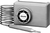
SMALL PRESSURE CONTROLS

High Volume OEM Item
Type LTB, ETB, HTB & FTB
GENERAL DESCRIPTION
• Factory set pressure switch designed for use in refriger ation units of quantity pr oduction such as r oom air conditioner (heat pump), packaged air conditioner (heat pump), water chiller etc.

• With SPDT contact mechanism.
• Models identified with electrical rating code L can be used for minimum 0.02A/125V.AC rating.
• Models with 0.78 to 1.96 MPa {8 to 20 kgf/cm2} range are also available for HTB and FTB.
• Models with 0.098 MPa {1 kgf/cm2} differential are also available for HTB (max. range limit: 1.27 MPa {13 kgf/ cm2}).
applicable (available
(available
SPECIFICATIONS
Type HTB
Type FTB
TYPE NUMBER SELECTION
LTB–A301
LTB–A302
LTB–A303
LTB–A304
LTB–A305
LTB–A306
ETB–A301
ETB–A302
ETB–A303
ETB–A304
ETB–A306
HTB–A301
HTB–A302
HTB–A303
HTB–A304
HTB–A305
HTB–A306
FTB–A301
FTB–A302
FTB–A303
FTB–A304
FTB–A305
FTB–A306
Pressure
Pressure
ELECTRICAL RATINGS
Non-Inductive
11
mark
upon request) UL recognized
upon request)
Volume OEM Item
Rated Voltage (V) Rated Current (A) Terminal Power Factor (cosφ) H Rating M Rating L Rating 125V.AC 250V.AC 125V.AC 250V.AC 125V.AC 250V.AC
Current C–L 1 1 to 10 1 to 10 1 to 3 0.5 to 1.5 0.02 to 2 0.02 to 1 Inductive Current Full Load 0.75 1 to 6 1 to 6 1 to 2 0.5 to 1 Inrush Current 1 to 24 1 to 24 1 to 8 0.5 to 4 0.02 to 8 0.02 to 4 Non-Inductive Current C–H 1 1 to 16 1 to 16 0.5 to 5 0.02 to 2 0.02 to 1 Inductive Current Full Load 0.75 1 to 6 0.5 to 4 Inrush Current 1 to 64 1 to 64 1 to 24 0.5 to 16 0.02 to 8 0.02 to 4
Unit: MPa {kgf/cm2} * Refer to Electrical Ratings Table in the list below Catalog No. Application Range Differential Factory Setting Max. Working Pressure Pressure Connections Electrical Ratings Wt. Min.(kg) Max. On Off
Low
0 0.392 {4} 0.059 to 0.147 {0.6 to 1.5} 0.294 {3} 0.196 {2} 1.5 {15} H 0.08
M
L
H
M
L
0.098 {1} 0.245 {2.5} Automatic operation on pressure decrease and manual reset on pressure increase Manual Reset 0.098 {1} H 0.1
M
L
H ETB–A305 M
L
High
0.78 {8} 1.96 {20} 0.29 to 0.49 {3 to 5} 1.96 {20} 2.45 {25} 3.3 {33} H 0.09
M
L
1.96 {20} 2.94 {30} 0.29 to 0.69 {3 to 7} H
M
L
0.78 {8} 2.94 {30} Automatic operation on pressure increase and manual reset on pressure decrease Manual Reset H 0.1
M
L
H
M
L *
• Fluid temperature: 20 to 120°C • Ambient temperature: 20 to 70°C Correo: xbombas@gmail.com Telefono: 55 5378 7190
12 CONTACT FUNCTIONS PRESSURE CONNECTIONS DIMENSIONS ・1/4" Solder Connection is also available upon request. C H L C H L M2 C H M1L Type LTB & HTB Type ETB (M2 : Manual Reset) Type FTB (M1 : Manual Reset) φ2.4×1000 Capillary Tube φ2.4×1000 Capillary Tube Dust Protection Cap 1/4" Flare Nut 68 36 36 2 M4×0.7 2 M4×0.7 18 24.5 18 26 Max. 47 Max. 50 55 55 18 26 18 26 13.9 13.5 Max. 50 Max. 50 55 55 Faston Terminal 3 #250 Faston Terminal 3 #250 φ2.4×1000 φ2.4×1000 64.5 36 64.5 36 2 M4×0.7 2 M4×0.7 φ8 Reset Button Faston Terminal 3 #250 Faston Terminal 3 #250 φ2.4×1000 φ2.4×1000 64.5 Type LTB Type ETB Type HTB Type FTB ↑: Operating direction on press. increase at High Press.Side M1 ↓, M2 ↑: Operating direction on manual reset Unit: mm C Common Terminal L Close on Pressure Increase H Close on Pressure Decrease Correo: xbombas@gmail.com Telefono: 55 5378 7190
SINGLE FUNCTION PRESSURE CONTROLS


Type SNS & HNS
GENERAL
Type
TYPE NUMBER SELECTION
SNS–C101X 0.06 { 50cmHg} 0.1 {1} 0.015 {0.15} 0.05 {0.5} 0.025 {0.25} 0.05 {0.5} 0.3 {3}
SNS–C102X 0.02 { 20cmHg} 0.2 {2} 0.025 {0.25} 0.15 {1.5} 0.5 {5}
SNS–C103X 0.06 { 50cmHg} 0.3 {3} 0.035 {0.35} 0.2 {2} 0.05 {0.5} 0.15 {1.5} 1 {10}
SNS–C104X 0.06 { 50cmHg} 0.4 {4} 0.04 {0.4} 0.1 {1} 0.2 {2} 1.5 {15}
SNS–C106X 0.06 { 50cmHg} 0.6 {6} 0.06 {0.6} 0.4 {4} 0.2 {2} 0.3 {3}
SNS–C110X 0.1 {1} 1 {10} 0.1 {1} 0.3 {3} 0.4 {4} 0.6 {6}
SNS–C120X 0.5 {5} 2 {20} 0.2 {2} 0.5 {5} 1.2 {12} 1.5 {15} 3 {30}
SNS–C130X 3 {30} 0.3 {3} 1 {10} 2 {20} 2.5 {25} 3.3 {33}
SNS–C135X
SNS–C102XM2
Diagram 1 0.33
13
DESCRIPTION • For use with fluorinated refrigerants as well as with air and water (Allowable fluid temp.: −20 to 120°C) • Type SNS for universal application. • Type HNS for high pressure safety cut out. • Available drip proof enclosure for marine application or explosion proof enclosure for special application. • Mounting bracket is supplied as standard. • With SPDT contact mechanism. • IP44 with upper lid (option). • Stainless steel models are available upon request. Catalog No. Range Manual Reset Factory Setting Max. Working Pressure Contact Function Wt. Min.(kg) Max. Off On HNS–C130XM1 0.8 {8} 3 {30} Automatic operation on pressure increase, and manual reset on pressure decrease ※2 2 {20} Manual Reset 3.3 {33} Diagram 4 0.24 * Based on the 1–3 terminal connection. ・ Enciosure: IP20 ・ Drip Proof Models: Available upon request. (Refer to page 48, 49, 50, 51.) Type HNS–Manual reset type Unit: MPa {kgf/cm2} ma rk applicable (available upon re que st) UL re cognize d (available upon re que st)
SNS Type HNS Catalog No. Range Differential Factory Setting Max. Working Pressure Contact Function Wt. Min.(kg) Max. Min. Max. Off (On) On (Off)
1 {10} 3.5 {35} 0.5 {5} 1.5 {15} 2.5 {25} 3 {30} 3.8 {38}
Type SNS–Automatic reset type Unit: MPa {kgf/cm2} Catalog No. Range Manual Reset Factory Setting Max. Working Pressure Contact Function Wt. Min.(kg) Max. Off On
0.02 { 20cmHg} 0.2 {2} Automatic operation on pressure decreasse, and manual reset on pressure increase ※1 0.025 {0.25} Manual Reset 0.5 {5} Diagram 2 0.33SNS–C106XM2 0.06 { 50cmHg} 0.6 {6} 0.2 {2} 1.5 {15} SNS–C130XM2 0.5 {5} 3 {30} 2 {20} 3.3 {33} * Based on the 1–3 terminal connection. Type SNS–Manual reset type Unit: MPa {kgf/cm2} * Catalog No. Range Differential Factory Setting Max. Working Pressure Contact Function Wt. Min.(kg) Max. Fixed Off On HNS–C130X 0.8 {8} 3 {30} 0.3 to 0.5 {3 to 5} 2 {20} 1.6 {16} 3.3 {33} Diagram 3 0.24 Type HNS–Automatic reset rype Unit: MPa {kgf/cm2} * Based on the 1–3 terminal connection. SPECIFICATIONS • Fluid temperature: 20 to 120°C • Ambient temperature: 20 to 70°C ※1 Please press the reset button after the pressure increased at specified point. Pressure Range : 02 about 0.04 MPa 06 about 0.1 MPa 30 about 0.5 MPa ※2 Please press the reset button after the pressure decreased about 0.7 MPa or less. * * Correo: xbombas@gmail.com Telefono: 55 5378 7190
SNS
SNS–C102X 99.7 SNS–C103X
SNS–C101X 113.3 22.4
SNS–C104X 96.8SNS–C106X
SNS–C110X
SNS–C120X 95.9 18.4SNS–C130X 93.5 SNS–C135X
SNS–C102XM2 99.7 22.4 SNS–C106XM2 96.8 SNS–C130XM2 93.5 18.4
14 ELECTRICAL RATINGS PRESSURE CONNECTIONS 1/4" Flare 7/16 20 Thread 1/4" Flare Nut φ2.4×1000 Capillary Tube CONTACT FUNCTIONS 1 5 3 1 5 3 1 3 5 1 3 M15 M2 (59) (19) (17.4) φ22 9.4 63.1 (91) φ6(1/4") Flare Nut Reset Button (54) (48.8) 33.4 4 M4×0.7 Thread Mounting Hole for Bracket (20.8) 25 ± 0.5 (17.3) Range Adjusting Screw Standard Diagram 1 Diagram 2 DIMENSIONS Standard ↑: Operating direction on press. increase at High Press. Side M1↓, M2↑: Operating direction on manual Referreset to page 45, 46. Unit: mm Rated Voltage (V) Rated Current (A) Power Factor (cosφ) 125/250V AC Non-Inductive Current 1 12 Inductive Current Full Load 0.75 Inrush Current 72 Diagram 1 & 2 Diagram 3 & 4 1 Common Terminal Common Terminal 3 Open on Pressure Increase Open on Pressure Increase 5 Open on Pressure Decrease Open on Pressure Decrease Catalog No. Unit: mm A B
Diagram 3 Diagram 4 Type HNS Type
4‐M4×0.7 Thread Mounting Hole for Bracket (54) (50) 36.4 22.4 (20.8) 25±0.5 (17.3) Reset (9.4)Button 63.1 (A) (B) 80 Differential Adjusting Screw Range Adjusting Screw φ6(1/4") Flare Nut 20.5 Correo: xbombas@gmail.com Telefono: 55 5378 7190
DUAL PRESSURE CONTROLS

Type DNS GENERAL DESCRIPTION
• For use with fluorinated refrigerants as well as with air and water (Allowable Fluid Temp.: 20 to 120°C)
• Various contact functions are available.
• Available drip proof enclosure for marine application or explosion proof enclosure for special application.
• Mounting bracket is supplied as standard.
• IP44 with upper lid (option).
• Stainless steel models are available upon request.
mark applicable (available upon request) UL recognized (available upon request)
TYPE NUMBER SELECTION
Automatic reset type
Unit: MPa {kgf/cm2}
Catalog No. Pressure Side Range Differential Factory Setting Max. Working Pressure Contact Function Wt. Min.(kg) Max. Min. Max. Off On
DNS–D304X
DNS–D306X
DNS–D604X
DNS–D606X
Low Side 0.06 { 50cmHg} 0.4 {4} 0.04 {0.4} 0.2 {2} 0.1 {1} 0.2 {2} 1.5 {15}
High Side 0.8 {8} 3 {30} Approx. 0.4 fixed {Approx. 4 fixed} 2 {20} 1.6 {16} 3.3 {33}
Low Side 0.06 { 50cmHg} 0.6 {6} 0.06 {0.6} 0.4 {4} 0.2 {2} 0.3 {3} 1.5 {15}
High Side 0.8 {8} 3 {30} Approx. 0.4 fixed {Approx. 4 fixed} 2 {20} 1.6 {16} 3.3 {33}
Low Side 0.06 { 50cmHg} 0.4 {4} 0.04 {0.4} 0.2 {2} 0.1 {1} 0.2 {2} 1.5 {15}
Diagram 1 0.49
Diagram High3 Side 0.8 {8} 3 {30} Approx. 0.4 fixed {Approx. 4 fixed} 2 {20} 1.6 {16} 3.3 {33}
Low Side 0.06 { 50cmHg} 0.6 {6} 0.06 {0.6} 0.4 {4} 0.2 {2} 0.3 {3} 1.5 {15}
High Side 0.8 {8} 3 {30} Approx. 0.4 fixed {Approx. 4 fixed} 2 {20} 1.6 {16} 3.3 {33}
Manual reset type
Catalog No. Pressure Side Range
Factory Setting Max. Working Pressure Contact Function Wt. Min.(kg)
Low Side 0.06 { 50cmHg}
{4}
{2} 0.1 {1} 0.2 {2} 1.5
DNS–D304XM
DNS–D306XM
Low
15
Enclosure: IP20 ・ Drip Proof Models: Available upon request. (Refer to Pages 49, 50.) ※1 Please press the reset button after the pressure increased about 0.1 MPa or more. ※2 Please press the reset button after the pressure decreased about 0.7 MPa or less.
Differential
Max. Min. Max. Off On
0.4
0.04 {0.4} 0.2
{15} Diagram 2 0.49 High Side 0.8 {8} 3 {30} Automatic operation on pressure increase, and manual reset on pressure decrease ※2 2 {20} manual reset 3.3 {33}
Side 0.06 { 50cmHg} 0.6 {6} 0.06 {0.6} 0.4 {4} 0.2 {2} 0.3 {3} 1.5 {15} High Side 0.8 {8} 3 {30} Automatic operation on pressure increase, and manual reset on pressure decrease ※2 2 {20} manual reset 3.3 {33} DNS–D604XM Low Side 0.06 { 50cmHg} 0.4 {4} 0.04 {0.4} 0.2 {2} 0.1 {1} 0.2 {2} 1.5 {15} Diagram 4 High Side 0.8 {8} 3 {30} Automatic operation on pressure increase, and manual reset on pressure decrease ※2 2 {20} manual reset 3.3 {33} DNS–D606XM Low Side 0.06 { 50cmHg} 0.6 {6} 0.06 {0.6} 0.4 {4} 0.2 {2} 0.3 {3} 1.5 {15} High Side 0.8 {8} 3 {30} Automatic operation on pressure increase, and manual reset on pressure decrease ※2 2 {20} manual reset 3.3 {33} DNS–D606XMM Low Side 0.06{ 50cmHg} 0.6 {6} Automatic operation on pressure decrease, and manual reset on pressure increase ※1 0.2 {2} 1.5 {15} Diagram 5 High Side 0.8 {8} 3 {30} Automatic operation on pressure increase, and manual reset on pressure decrease ※2 2 {20} 3.3 {33} Unit: MPa {kgf/cm2} SPECIFICATIONS • Fluid temperature: 20 to 120°C • Ambient temperature: 20 to 70°C Correo: xbombas@gmail.com Telefono: 55 5378 7190
16 CONTACT FUNCTIONS 1 4 2H L 3 1 4 H M 2 L 3 1 54 26 H L 3 1 54 26 H M L 3 1 54 26 H M L M 3 ↑ L: Operating direction on press. increase at Low Press. Side ↑ H: Operating direction on press. increase at High Press. Side ↓ M: Operating direction on manual reset PRESSURE CONNECTIONS DIMENSIONS Standard Model φ6(1/4") Flare Nut 20.5 20.5 Reset Button (17.4) (22.4) 4‐M4×0.7 Thread Mounting Hole for Bracket (20.8) 25±0.5 (17.3) (54) (50) 36.4 22.4 (9.4) (96.8)63.1 φ22 (24)63 (106) High Range Adjusting Screw Low Range Adjusting Screw φ34.4 Low Range Differential Adjusting Screw 1/4" Flare Nut φ2.4x1000 Capillary 1/4"Tube Flare 7/16-20 Thread Diagram 1 Diagram 2 Diagram 3 Diagram 4 Diagram 5 Standard Unit: mm Refer to Pages 45, 46 ELECTRICAL RATINGS Rated Voltage (V) Rated Current (A) Power Factor (cosφ) 125/250V AC Non-Inductive Current 1 12 Inductive Current Full Load 0.75 Inrush Current 72 Minimum contact capacity: 50mA Correo: xbombas@gmail.com Telefono: 55 5378 7190
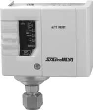
SINGLE FUNCTION PRESSURE CONTROLS

Type SYS GENERAL DESCRIPTION
TYPE NUMBER SELECTION
SYS–C103X0 R404A,R407C R134a,R22
reset type
Catalog No. Refrigerant
SYS–C106X0M2
SYS–C130X0M2
R407C
Setting
Working Pressure Contact Function
MPa {kgf/cm
Factory Setting Max. Working Pressure Contact Function Wt. Min.(kg)
Range Manual Reset
Off (On) On (Off)
1.65 {16.5} Diagram
0.25
17
• Type SYS is standard model. Reliable performance, and long life products. • Applicable for R410A (SYS C140X0) • Scale plate with significantly clear visibility • Compact and light weight ma rk applicable (available upon re que st) Manual
Unit:
2} ・ Enclosure: IP20 *1 Standard unit display is MPa. Other unit displays are available upon request by changing “X0” portion of a catalog number [X0: MPa, X1: bar, X2: kgf/cm2 , X3: kPa, X4: lb/in2 , X5: psi] *2 The products other than SYS–C140X0 are not compatible with R410A refrigerant. *3 Indicates the average value also considering instrumental errors.
Max.
R404A,
R134a, R22 0.06{ 50cmHg} 0.6 {6} Automatic operation on pressure decrease and manual reset on pressure increase 0.2 {2} Manual Reset
2
0.5 {5} 3 {30} 1.5 {15} 3.3 {33} *1 *2
Automatic reset type Unit: MPa {kgf/cm2} Catalog No. Refrigerant Range Differential Factory
Max.
Wt. Min.(kg) Max. Min. Max. Off (On) On (Off)
0.06 { 50cmHg} 0.3 {3} 0.035 {0.35} 0.2 {2} 0.05 {0.5} 0.15 {1.5} 1.65 {16.5} Diagram 1 0.25 SYS–C106X0 0.6 {6} 0.06 {0.6} 0.4 {4} 0.2 {2} 0.3 {3} SYS–C110X0 0.1 {1} 1 {10} 0.1 {1} 0.3 {3} 0.4 {4} 0.6 {6} SYS–C130X0 0.5 {5} 3 {30} 0.3 {3} 1 {10} 1.5 {15} 2 {20} 3.3 {33} SYS–C135X0 1 {10} 3.5 {35} 0.5 {5} 1.5 {15} 2 {20} 2.5 {25} 3.8 {38} SYS–C140X0 R410A etc. 4.3 {43} 1 {10} 4.7 {47} *1 *2 *3 DIMENSIONS 7/16 (18)20UNF A U T O R E S E T (48) (75) A 25±0.5 31.1 (86.5)(65.5)25±0.5 21.4 4-M4×0.7 Thread Mounting Hole for Bracket Range Adjusting Screw Differential Adjusting Screw Reset Button Unit: mm ELECTRICAL RATINGS CONTACT FUNCTIONS 1 5 3 1 5 3 1 3 5 1 3 M15 M2 Diagram 1 Diagram 2 ↑: Operating direction on press. increase at High Press. Side M2↑: Operating direction on manual reset Rated Voltage (V) Rated Current (A) Power Factor (cosφ) 125/250V AC Non-Inductive Current 1 12 Inductive Current Full Load 0.75 Inrush Current 72 Diagram 1 & 2 1 Common Terminal 3 Close on Pressure Increase 5 Close on Pressure Decrease Minimum contact capacity: 50mA Catalog No. Unit: mm A SYS–C103 to 110 17.7 SYS–C130 to 140 16.7 SPECIFICATIONS • Fluid temperature: 20 to 120°C • Ambient temperature: 20 to 70°C Correo: xbombas@gmail.com Telefono: 55 5378 7190
TYPE NUMBER
DYS–D306X0M
DYS–D606X0M
Low Side
High Side
Low
Low
DYS–D606X0MM
CONTACT
1.65 {16.5}
Diagram 2
ELECTRICAL

18 A U T O R E S E T 7/16 74.220UNF (86.5)(65.5) (86.5) (110) (17.9) (48) 25±0.5 15.9 17.7 25±0.5 4-M4×0.7 Thread Mounting Hole for Bracket 40.4 20.3 Low Range Adjusting Screw Low Range Differential Adjusting Screw High Range Adjusting Screw High Press. Side Reset LowButton Press. Side Reset Button DIMENSIONS DUAL PRESSURE CONTROLS Type DYS GENERAL DESCRIPTION • Type DYS is dual pressure controls that is integrated with over pressure protection of the high pressure side and control of low pressure side of the refrigeration unit. • Scale plate with significantly clear visibility • Compact and light weight mark applicable (available upon request)
SELECTION Automatic reset type Unit: MPa {kgf/cm2} Catalog No. Pressure Side Range Differential Factory Setting Max. Working Pressure Contact Function Wt. Min.(kg) Max. Min. Max. Off On DYS–D306X0 Low Side 0.06 { 50cmHg} 0.6 {6} 0.06 {0.6} 0.4 {4} 0.2 {2} 0.3 {3} 1.65 {16.5} Diagram 1 High0.40 Side 0.8 {8} 3 {30} Approx.0.5 fixed. {Approx.5 fixed.} 2 {20} 1.5 {15} 3.3 {33} DYS–D606X0 Low Side 0.06 { 50cmHg} 0.6 {6} 0.06 {0.6} 0.4 {4} 0.2 {2} 0.3 {3} 1.65 {16.5} Diagram 3 High Side 0.8 {8} 3 {30} Approx.0.5 fixed. {Approx.5 fixed.} 2 {20} 1.5 {15} 3.3 {33} *1 *2 Manual reset type Unit: MPa {kgf/cm2} ・ Enclosure: IP20 *1 Standard unit display is MPa. Other unit displays are available upon request by changing “X0” portion of a catalog number [X0: MPa, X1: bar, X2: kgf/cm2 , X3: kPa, X4: lb/in2 , X5: psi] *2 Indicates the average value also considering instrumental errors. Catalog No. Pressure Side Range Differential Factory Setting Max. Working Pressure Contact Function Wt. Min.(kg) Max. Min. Max. Off On
0.06 { 50cmHg} 0.6 {6} 0.06 {0.6} 0.4 {4} 0.2 {2} 0.3 {3}
0.40
0.8 {8} 3 {30} Automatic operation on pressure increase and manual reset on pressure decrease 2 {20} manual reset 3.3 {33}
Side 0.06{ 50cmHg} 0.6 {6} 0.06 {0.6} 0.4 {4} 0.2 {2} 0.3 {3} 1.65 {16.5} Diagram 4 High Side 0.8 {8} 3 {30} Automatic operation on pressure increase and manual reset on pressure decrease 2 {20} manual reset 3.3 {33}
Side 0.06{ 50cmHg} 0.6 {6} Automatic operation on pressure decrease and manual reset on pressure increase 0.2 {2} 1.65 {16.5} Diagram 5 High Side 0.8 {8} 3 {30} Automatic operation on pressure increase and manual reset on pressure decrease 2 {20} 3.3 {33} *1 *2 Unit: mm
RATINGS Rated Voltage (V) Rated Current (A) Power Factor (cosφ) 125/250V AC Non-Inductive Current 1 12 Inductive Current Full Load 0.75 Inrush Current 72 Minimum contact capacity: 50mA
FUNCTIONS Refer to Pages 16 SPECIFICATIONS • Fluid temperature: 20 to 120°C • Ambient temperature: 20 to 70°C Correo: xbombas@gmail.com Telefono: 55 5378 7190
CONTROLS WITH NARROW DIFFERENTIAL
Type FNS & ANS
GENERAL DESCRIPTION
SPECIFICATIONS
• Fluid temperature: 20 to 120°C
• Ambient temperature: 20 to 70°C
TYPE NUMBER SELECTION
Catalog No.
Range Differential Factory Setting Max. Working Pressure Wt. Min.(kg) Max. Fixed Off On

FNS–C101X 0.06 { 50cmHg}
FNS–C102X 0.02 { 20cmHg} 0.2 {2} 0.008 Approx. {0.08 Approx.} (0.042) {(0.42)} 0.05 {0.5} 0.5 {5}
0.1 {1} 0.006 Approx. {0.06 Approx.} (0.019) {(0.19)} 0.025 {0.25} 0.3 {3} 0.32
FNS–C106X 0.06 { 50cmHg} 0.6 {6} 0.02 Approx. {0.2 Approx.} (0.28) {(2.8)} 0.3 {3.0} 1.5 {15}
FNS–C110X 0.1 {1} 1 {10} 0.025 Approx. {0.25 Approx.} (0.575) {(5.75)} 0.6 {6.0}
FNS–C130X 0.5 {5} 3 {30} 0.12 Approx. {1.2 Approx.} (2.38) {(23.8)} 2.5 {25} 3.3 {33}
Type
ANS–C101XB 0.06
50cmHg}
ANS–C103XB 0.02 { 20cmHg} 0.3 {3} 0.008 {0.08} 0.01 {0.1} 0.018 {0.18} 0.027 {0.27} 0.141 {1.41} 0.15 {1.5} 1 {10}
0.007 {0.07} 0.007 {0.07} 0.014 {0.14} 0.015 {0.15} 0.018 {0.18} 0.025 {0.25} 0.3 {3} 0.32
ANS–C106XB 0.06 { 50cmHg} 0.6 {6} 0.015 {0.15} 0.018 {0.18} 0.03 {0.3} 0.045 {0.45} 0.28 {2.84} 0.3 {3.0} 1.5 {15}
ANS–C110XB 0.1 {1} 1 {10} 0.02 {0.2} 0.03 {0.3} 0.045 {0.45} 0.07 {0.7} 0.575 {5.75} 0.6 {6.0}
ANS–C130XB 0.5 {5} 3 {30} 0.12 {1.2} 0.2 {2.0}
0.23 {2.3} 0.37 {3.7} 2.32 {23.2} 2.5 {25} 3.3 {33}
ANS–C135XB 1 {10} 3.5 {35} 0.24 {2.4} 0.39 {3.9} 2.82 {28.2} 3 {30} 3.8 {38}
19 PRESSURE
• For use with fluorinated refrigerants as well as with air and water • Type FNS with fixed narrow differential • Type ANS with adjustable narrow differential • Available drip proof enclosure for marine application or explosion proof enclosure for special application. • Mounting bracket is supplied as standard. • With SPDT contact mechanism. • IP44 with upper lid (option). Type FNS • Stainless steel models are available upon request.
Type FNS Fixed narrow differential type
ANS Adjustable narrow differential type ・ Enclosure: IP20 Drip Proof Models: Available upon request. (Refer to page 51.) Unit: MPa {kgf/cm2} Unit: MPa {kgf/cm2} mark applicable (available upon request) Type FNS
Type
ANS Catalog No. Range Differential Factory Setting Max. Working Pressure Wt. Min.(kg) Max. Min. Max. Bottom Top Bottom Top Off On
{
0.1 {1}
Correo: xbombas@gmail.com Telefono: 55 5378 7190
Catalog No.
Unit: mm
A B
FNS–C101X 113.3
FNS–C102X 99.7
FNS–C106X 96.8
FNS–C110X
22.4
FNS–C130X 93.5 18.4
mm
Catalog No.
A B
ANS–C101XB 113.3
ANS–C103XB 99.7
ANS–C106XB 96.8
ANS–C110XB
22.4
ANS–C130XB 93.5 18.4
ANS–C135XB
20 CONTACT FUNCTIONS 1 5 3 ↑: Operating direction on press. increase at High Press. Side PRESSURE CONNECTIONS 1/4" Flare DIMENSIONS Standard Model Type ANS MP 1.5MPa 0.06 0 0.2 0.4 0.6 RANGE 4 M4×0.7 Thread Mounting Hole for Bracket (50) 22.4 (20.8) 25 ± 0.5 (17.3) 63.1 ( A ) (B) 80 20.5 MPa Range Adjusting Screw φ6(1/4") Flare Nut MP 1.5MPa 0.06 0 0.2 0.4 0.6 RANGE 4 M4×0.7 Thread Mounting Hole for Bracket (50) 8 22.4 (20.8) 25 ± 0.5 (17.3) 63.1 ( A ) (B) 80 20.5 φ21 MPa Range Adjusting Dial φ6(1/4") Flare Nut ELECTRICAL RATINGS Unit: mm Type FNS Refer to page 45, 46. Standard
Unit:
Rated Voltage (V) Rated Current (A) Power Factor (cosφ) 125/250V AC Non-Inductive Current 1 12 Inductive Current Full Load 0.75 Inrush Current 72 1 Common Terminal 3 Close on Pressure Increase 5 Close on Pressure Decrease Correo: xbombas@gmail.com Telefono: 55 5378 7190
OIL PROTECTION CONTROLS
Type ONS
GENERAL DESCRIPTION
SPECIFICATIONS
•
TYPE NUMBER SELECTION
ONS–C106XQ1
ONS–C106XQ2
ONS–C106XQ3 110
Specification Connection Wt.
ONS–C106XQ4 45 110/220V. ACONS–C106XQ5 90
ONS–C106XQ6 110
ONS–C106XQ7 45 115/230V. ACONS–C106XQ8 90
ONS–C106XQ9 110
ONS–C106XQ10 45 120/240V. ACONS–C106XQ11 90
ONS–C106XQ12 110
ONS–C106XL1Q2 90
ONS–C106XL1Q1 45 100/200V. AC
100/200V. AC Standard (SPST) without Alarm Contact

1/4" Flare Nut 0.55
ONS–C106XL1Q3 110
ONS–C106XL1Q4 45 110/220V. ACONS–C106XL1Q5 90
ONS–C106XL1Q6 110
ONS–C106XL1Q7 45 115/230V. ACONS–C106XL1Q8 90
ONS–C106XL1Q9 110
ONS–C106XL1Q10 45 120/240V. ACONS–C106XL1Q11 90
Approx. 0.05
ONS–C106XL1Q12 110
1000mm Capil. Tube with 1/4" Flare Nut 0.62
{0.5}
ONS–C106XQ26 90
ONS–C106XQ25 45 100/200V. AC
0.5
ONS–C106XQ27 110
ONS–C106XQ28 45 110/220V. ACONS–C106XQ29 90
ONS–C106XQ30 110
1/4" Flare Nut 0.55
ONS–C106XQ31 45 115/230V. AC
ONS–C106XQ32 90
ONS–C106XQ33
ONS–C106XQ34
ONS–C106XQ35
ONS–C106XQ36
ONS–C106XL1Q25
ONS–C106XL1Q26
ONS–C106XL1Q27
ONS–C106XL1Q28
ONS–C106XL1Q29
ONS–C106XL1Q30
ONS–C106XL1Q31
ONS–C106XL1Q32
ONS–C106XL1Q33
ONS–C106XL1Q34
ONS–C106XL1Q35
ONS–C106XL1Q36
120/240V. AC
With Alarm Contact (SPDT)
21
• Provides dependable protection against major break down on pressure lubricated refrigeration compressors by guarding against low lubrication oil pressure. • With manual reset. • Built in time delay switch. • Mounting bracket is supplied as standard. • Stainless steel models are available upon request.
Unit: MPa {kgf/cm2} Max. Working Pressure: 1.5 MPa {15 kgf/cm2} Limit of Pressure Diff. Hp≧Lp: 1.5 MPa {15 kgf/cm2}, Hp represents oil pump discharge pressure and Lp crank case pressure. ・ Enclosure: IP20 ・ Drip Proof Models: Available upon request. (Refer to page 52.) ※After the timer operation, please press the reset button later 30 minutes.
mark applicable (available upon request) Catalog No. Range Differential Timer
Min.(kg) Max. Fixed Delay Time(sec.) Timer Voltage Timer Circuit
0.05
0.35 {3.5}
Approx.
45
90
110
45
90
110
45 100/200V. AC 1000mm Capil. Tube with 1/4" Flare Nut 0.62
90
110
45 110/220V. AC
90
110
45 115/230V. AC
90
110
45 120/240V. AC
90
110
Fluid temperature: 20 to 120°C • Ambient temperature: 20 to 70°C Correo: xbombas@gmail.com Telefono: 55 5378 7190
PRESSURE CONNECTIONS
22 ELECTRICAL RATINGS CONTACT FUNCTIONS ↑: Operating direction of pressure increase c : Operating direction of timer when energized M ↓: Operating direction of manual reset 1 100V L2 L1 ML3 Motor Circuit Heater Heater Circuit 200V 110/220V AC, 120/240V AC etc. available
DIMENSIONS 1/4" Flare 7/16 20 Thread 1/4" Flare Nut φ2.4×1000 Capillary Tube Standard MP 1.5MPa 0.1 0.2 0.30.35 RANGE H P MPa (20.5) 20.5 (20.5) (116) 18.9 62.8 (141.2) (17.3) (22.4) (49.1) (51) 25±0.5 (13) 34.4φ 4 M4×0.7 Thread Mounting Hole for Bracket φ6(1/4")Flare Nut Reset Button Lead wire for Alarm Contact Unit: mm Refer to page 45, 46. ( L3: Alarm Contact provided with a lead wire approx.)φ3.5×100mm with a soldered terminal. Rated Voltage (V) Rated Current (A) Power Factor (cosφ) 125/250V AC Non-Inductive Current 1 3.5 Inductive Current Full Load 0.75 3 Inrush Current 10 1 Heater Circuit Common Terminal 100 100V Power Supply Terminal 200 200V Power Supply Terminal L1 Motor Circuit Open on Decrease of Pressure Difference L2 Main Contact L3 Alarm Contact Correo: xbombas@gmail.com Telefono: 55 5378 7190
WNS
0.5 {5}
{15} 1.5 {15}

CONTACT
23 GENERAL DESCRIPTION Type
• Differential pressure is adjustable controller • It is suitable for water cuttoff detection of cooling water circuit. • Standard Type : IP20 Type YNS • Narrow differ ntial pressure (fixed) controller • Standard Type : IP20 PRESSURE CONNECTIONS DIMENSIONS 1/4" Flare 7/16 20 Thread MP 0.251.5MPa 0.2 0.15 0.1 0.05 0.1 0.2 0.35 RANGE DIFF. 20.5 63.1 20.5 (B) (D) (C) (24) (80) (20.8) (50)(22.4) 25±0.5 (17.3) φ A H P MPa 4 M4×0.7 Thread Mounting Hole for Bracket φ6(1/4") Flare Nut Standard DIFFERENTIAL PRESSURE CONTROLS Type WNS & YNS Unit: mm mark applicable (available upon request) UL recognized (available upon request) Refer to page 45, 46. TYPE NUMBER SELECTION Type WNS Adjustable differential type for water, air and fluorinated refrigerant Unit: MPa {kgf/cm2} Catalog No. Range Differential Factory Setting Max. Working Pressure Limit of Press. Differential (HP > LP) Wt. Min.(kg) Max. Min. Max Off On WNS–C102X 0.03 {0.3} 0.2 {2} 0.03 {0.3} 0.15 {1.5} 0.05 {0.5} 0.02 {0.2} 0.5 {5} 0.5 {5} 0.43 WNS–C106X 0.05 {0.5} 0.35 {3.5} 0.05 {0.5} 0.25 {2.5} 0.1 {1.0} 0.05 {0.5} 1.5 {15} 1.5 {15} ELECTRICAL RATINGS
FUNCTIONS 1 5 3 ↑: Operating direction on press. increase at High Press. Side Rated Voltage (V) Rated Current (A) Power Factor (cosφ) 125/250V AC Non-Inductive Current 1 12 Inductive Current Full Load 0.75 Inrush Current 72 1 Common Terminal 3 Close on Pressure Increase 5 Close on Pressure Decrease Catalog No. Unit: mm φA B C D WNS–C102X 38.5 50.0 39.0 147.2 WNS–C106X 34.4 47.0 36.0 141.2 SPECIFICATIONS • Fluid temperature: 20 to 120°C • Ambient temperature: 20 to 70°C • For water, air and fluorinated refrigerant HP......High Side Press. LP......Low Side Press. ・Enclosure: IP20 Drip proof models: Available upon request. (Refer to page 52.) ・Please contact us if other range models are required. Type YNS Fixed narrow differential Catalog No. Range Differential Factory Setting Max. Working Pressure Limit of Press. Differential (HP > LP) Wt. Min.(kg) Max. Fixed Off On YNS–C102X 0.02 {0.2} 0.2 {2} 0.015 {0.15} approx. 0.05 {0.5} (0.035) {(0.35)} 0.5 {5}
0.43 YNS–C106X 0.025 {0.25} 0.35 {3.5} 0.025 {0.25} approx. 0.15 {1.5} (0.125) {(1.25)} 1.5
Unit: MPa {kgf/cm2} Correo: xbombas@gmail.com Telefono: 55 5378 7190
GENERAL
SPECIFICATIONS
CFE–SC50B–103

24
DESCRIPTION • All functions can be set by 3 push button switches. • Independent ON/OFF setting. • ON Delay timer function. • Pressure calibration
Supply voltage: 230V AC±10% 50/60Hz Output contact rating: 125/250V AC 1A(cosφ=1) SPST Delay timer function: 0 to 240 sec (step=1sec.) Fluid: Refrigerants (excluding ammonia), water, air. Ambient temp. range: 10 to 60°C Storage temperature range: 10 to 60°C Pressure connection: 7/16–20UNF male flare 1/4" Enclosure: IPX2 * In case pressure decrease than the ON pressure during working of Delay timer, timer is reset, and does not tur n on. * In case pr essur e incr ease than the ON pressure during working of Delay timer, timer is reset, and does not tur n on. OPERATION OPERATION PATTERN DIMENSIONS WIRING Output NO C Power supply Power supply Load power supply Pressure switch unit Load OUTPUT Relay OUTPUT Relay Press Delay timer ON OFF ON OFF Press TimeTime OFF ON ON OFF Delay timer Output Relay OFF OFFON Output Relay ON Press. Increase Output Relay OFF ONOFF Output Relay ON Press. Increase 1/4" Flare Nut Attached 53.6 26.6 32.5 2512.8 25 2 M4×0.7 Screw mounting pitch 90 65.8 (28.2) DIGITAL PRESSURE CONTROLS Type CFE Unit: mm mark applicable (available upon request) During Set Low (LoC) During Set High (HiC) During Set Low (LoC) During Set High (HiC) DELAY TIMER OPERATION PATTERN TYPE NUMBER SELECTION Unit: MPa Catalog No. Setting/Indication Range Setting resolution Calibration range Airtight Pressure Wt. (kg) Min. Max. CFE–SC10B–001 0.095 0.995 0.005 ±0.03 3.85 0.29 CFE–SC35B–001 0 3.5 0.02 ±0.12 CFE–SC50B–001 0 5.0 0.02 ±0.3 5.5 CFE–SC10B–101 0.95 bar 9.95 bar 0.05 bar ±0.3 bar 38.5 bar CFE–SC35B–102 0 bar 35 bar 0.2 bar ±1.2 bar
0 bar 50 bar 0.2 bar ±3.0 bar 55 bar Correo: xbombas@gmail.com Telefono: 55 5378 7190
SPECIFICATIONS

BE
042I–
050I–


017I–
020I–
030I–
035I–

042I–
to 1.7 {0 to 17}
to 2 {0 to 20}
0 to 3 {0 to 30}
0 to 3.5 {0 to 35}
F.S. Max. 10mA Min. 10 kΩ
{38.5}
4.56 {45.6}
5.5 {55}
3.85 {38.5} 0.04
{45.6}
{55}
{38.5}
BH
25 PRESSURE SENSORS High Volume OEM Item (Type NSK) Type NSK & XSK GENERAL DESCRIPTION • High reliability and accuracy • Double diaphragm structure • Diffusion silicone chip pressure sensor TYPE NUMBER SELECTION WIRING Type NSK Power Supply Connector Red White Black Type XSK Receiver Power Supply 10.5 to Connector28V.DC Red ReceiverWhite 1 2 3 1 3 5V. DC±0.25V. + + Unit: MPa {bar}
• Fluid temperature range: 30 to 120°C (Type NSK) 20 to 70°C (Type XSK) • Ambient temperature range: 30 to 100°C (Type NSK–BC, BE) 30 to 80°C (Type NSK–BH) 20 to 70°C (Type XSK) Type NSK–BC Type NSK–BE Type TXSK ype NSK–BH * Included non lineality hysteresis, and temperature drift * Accuracy of 2.5% or less is available upon request. ・ Enclosure: IP66 (Type NSK–BH) mark applicable (available upon request) UL recognized (available upon request) Catalog No. Pressure Range Supply Voltage Output Accuracy Current Consumption Load Resistance Airtight Pressure Wt. (kg) NSK BC 010I–*** 0 to 1 {0 to 10} 5V. DC ± 0.25V 0.5 to 3.5V DC or 0.5 to 4.5V. DC ±2.5% F.S. Max. 10mA Min. 10 kΩ 3.85
0.07 017I–*** 0 to 1.7 {0 to 17} 020I–*** 0 to 2 {0 to 20} 030I–*** 0 to 3 {0 to 30} 035I–*** 0 to 3.5 {0 to 35}
*** 0 to 4.15 {0 to 41.5}
*** 0 to 5 {0 to 50}
010I–*** 0 to 1 {0 to 10} 5V. DC ± 0.25V 0.5 to 3.5V DC or 0.5 to 4.5V. DC ±2.5%
*** 0
*** 0
***
***
*** 0 to 4.15 {0 to 41.5} 4.56
050I–*** 0 to 5 {0 to 50} 5.5
010D–*** 0 to 1 {0 to 10} 5V. DC ± 0.25V 0.5 to 3.5V DC or 0.5 to 4.5V. DC ±2.5% F.S. Max. 10mA Min. 10 kΩ 3.85
0.06 017D–*** 0 to 1.7 {0 to 17} 020D–*** 0 to 2 {0 to 20} 030D–*** 0 to 3 {0 to 30} 035D–*** 0 to 3.5 {0 to 35} 042D–*** 0 to 4.15 {0 to 41.5} 4.56 {45.6} 050D–*** 0 to 5 {0 to 50} 5.5 {55} XSK AC 10I–194 0.05 to 1 { 0.5 to 10} 10.5 to 28V. DC 4 to 20mA. DC ±3% F.S. Max. 100Ω at 12V. DC Max. 500Ω at 24V. DC 3.85 {38.5} 0.09 20I–194 0 to 2 {0 to 20} 30I–194 0 to 3 {0 to 30} 35I–194 0 to 3.5 {0 to 35} 50I–194 0 to 5 {0 to 50} 5.5 {55} * High Volume OEM Item Correo: xbombas@gmail.com Telefono: 55 5378 7190
26 DIMENSIONS Type NSK–BC (Molex connector) Type NSK–BE (Packard connector) Housing Body 7/16 20 UNF Flare 1/4" 1000 GNDVoutVcc (13.5) 11.8 (19.7) (16.8) (49) (7) 10.5 1.5 ± 0.1 PIN 1.6 ± 0.1 PINφ1.5 φ23.9 3 2 1 φ23.9 φ17 ( 16.8 ) (25.6) (54.9) GND Vcc Vout 7/16 20 UNF Flare 1/4" Type XSK (Molex connector) COM. Vcc 7/16 20 UNF Flare 1/4" Housing φBody 21.4 (66.3) (13.5) 31 1000 φ26.6 Type NSK–BH (Lead wire direct Connector) 1000 (φ6.35) (φ8) (3) (82.4)(56.3) (26) Unit: mm 58 67 23 25 20 7 7 2 φ4.5 30 • NSK Type No. NSK–PP02 (for NSK–BC, BE) ACCESSORY • Lead wire with connector is supplied as standard accessory except for NSK–BE type. OPTIONAL PARTS Bracket 26 24 24 5 5 15 58 67 2 φ4.5 21 • XSK Type No. YSK–PP02 Unit: mm Correo: xbombas@gmail.com Telefono: 55 5378 7190
•
Stainless
Standard
27 PRESSURE CONNECTIONS
Connection Material
steel pressure connection is available upon request. (R only) • Connection Style
connection style is 7/16–20UNF Female Flare with schrader depressor. The following connection styles are available upon request. A 7/16–20UNF Female Flare 1/4" with schrader depressor 7/16–20UNF Male Flare 1/4" R 1/4" Copper Solder (Type NSK–BH) A Type 1/8" NSK XSK 1/4" XSK 3/8" XSK Correo: xbombas@gmail.com Telefono: 55 5378 7190
TEMPERATURE & HUMIDITY
TEMPERATURE
LWS, FWS, RWS
TNS, CNS & INS
ALS & BLS
EWS
TEMPERATURE
PWS ROOM THERMOSTATS
ARS
THERMOSTATS
WRS
HUMIDISTATS
AHS
THERMOSTATS & DIGITAL HUMIDISTATS
ALE & BLE DIGITAL THERMOSTATS
Type TNE
CONTROLS 29–30 Type
&
TEMPERATURE CONTROLS 31–32 Type
TEMPERATURE CONTROLS ・・・・・・・・・・・・・・・・・・・ 33 Type
PROPORTIONAL
CONTROLS 34 Type
35–36 Type
ROOM
・・・・・・・・・・・・・・・・・・・・・・・ 37 Type
ROOM
38 Type
DIGITAL
・・ 39–42 Type
43
TEMPERA TURE & HUMIDITY CONTROLS
CONTROLS Correo: xbombas@gmail.com Telefono: 55 5378 7190
TEMPERATURE CONTROLS


SENSING
Type LWS,
GENERAL DESCRIPTION
& EWS
Type
TYPE
29
REMOTE / DIRECT
FWS, RWS
• Most suitable model can be selected from the variations of wide temperatur e range with either adjustable or fixed dif fer ential. Narr ow dif fer ential is further advantageous. • Sensing elements are air sensed and liquid sensed type depending on control media. Also, sensing element can be selected from remote or direct type depending on application. • Single pole double throw contacts allows use for either heating or cooling application, with large contact rating as well. • Adjusting mechanism is driver adjusting type as standar d on delivery, but a knob assembly and a concealed plate ar e also supplied as standar d accessories.
EWS Type LWS
NUMBER SELECTION (SPECIFICATIONS) Type LWS Set high type with standard remote sensing element Type FWS Air Sensed type with standard remote sensing element Unit: °C Unit: °C UL listed (available upon request) Catalog No. Temp. Adjusting Range Differential Bulb Size (mm) Ambient Temp. Limit of Bulb Temp. Wt. (kg)Type Designation Contact Model Differential Rating Capillary Length Min. Max. Min. Max. LWS– C1 030 A (Variable) G R Standard L1 (L = 1m) Option L2 (L = 2m) L3 (L = 3m) L5 (L = 5m) 35 30 2 7 φ9.5×100 20 to 70 60 0.45 060 5 60 90 090 25 90 φ9.5×85 120 120 40 120 2.5 8 φ9.5×70 150 160 95 160 185 200 Standard L1 (L = 1m) Option L2 (L = 2m) 135 200 230 240 175 240 265 030 F (Fixed) Standard L1 (L = 1m) Option L2 (L = 2m) L3 (L = 3m) L5 (L = 5m) 35 30 2 (Fixed) φ9.5×100 60 060 5 60 90 090 25 90 φ9.5×85 120 120 40 120 2.5 (Fixed) φ9.5×70 150 160 95 160 185 200 Standard L1 (L = 1m) Option L2 (L = 2m) 135 200 230 240 175 240 265 Catalog No. Temp. Adjusting Range Differential Bulb Size (mm) Ambient Temp. Limit of Bulb Temp. Wt. (kg)Type Designation Contact Model Differential Rating Capillary Length Min. Max. Min. Max. FWS– C1 030 A (Variable) G R Standard L1 (L = 1m) Option L2 (L = 2m) L3 (L = 3m) L5 (L = 5m) 35 30 2 7 Max. φ37×58 20 to 70 60 0.52 060 5 60 90 090 25 90 120 120 40 120 2.5 8 150 160 F (Fixed) 35 30 2 (Fixed) 60 200 5 60 90 240 25 90 120 030 40 120 2.5 (Fixed) 150 Correo: xbombas@gmail.com Telefono: 55 5378 7190
30 Type RWS with coiled capillary sensing element Type EWS with direct immersion sensing element ELECTRICAL RATINGS CONTACT STYLE C H L Models “set high” The dial indicates the high switch point ( Ⓒ Ⓛ close, Ⓒ Ⓗ open). The low switch point ( Ⓒ Ⓛ open, Ⓒ Ⓗ close) is obtained by deducting the differential from the high switch point. Arrow mark indicates a direction of switch action on temperature increase. DIMENSIONS 51.5 43.5 Capillary Tubeφ2 (16) 54 114 22.5 9.5φ 21 φ37 φ21 43.5 22.5 114 Max. 42φ 43.5 40 7486 2 φ6.2 Max.58 Max. 37φ Capillary Tube φ2 22.5 42 10.8φ (108) 70 Bulb Well R1/2" 52.5 2 M5×10 22.5 16 Type RWS Type EWS Unit: mm Unit: °C Unit: °C Type LWS Type FWS Catalog No. Temp. Adjusting Range Differential Sensing Element (mm) Ambient Temp. Limit of Tube Temp. Wt. (kg)Type Designation Contact Model Differential Rating Min. Max. Min. Max. RWS– C1 060 A (Variable) G R 5 60 2 7 Coiled Tube Max. φ42×40 20 to 60 60 0.43 034 10 35 1.4 5 20 to 70 70 054 10 55 20 to 70 70 060 F (Fixed) 5 60 2 (Fixed) 034 10 35 1.4(Fixed) 20 to 70 70 054 10 55 20 to 60 60 Catalog No. Temp. Adjusting Range Differential Sensing Element (mm) Ambient Temp. Limit of Tube Temp. Wt. (kg)Type Designation Contact Model Differential Rating Min. Max. Min. Max. EWS– C1 080 A (Variable) G R 0 80 2.5 8 φ10.8×70 20 to 70 110 0.51 120 40 120 150 160 95 160 185 080 F (Fixed) 0 80 2.5 (Fixed) 110 120 40 120 150 160 95 160 185 Electrical Rating Code Rated Voltage (V) Rated Current (A) Power Factor (cosφ) 125V AC 250V AC G Non-Inductive Current 1.0 0.5 to 16 0.5 to 8 Inductive Current Full Load 0.75 Inrush Current 96 48 R Non-Inductive Current 1.0 0.05 to 8.5 0.05 to 4.5 Inductive Current Full Load 0.75 Inrush Current 51 27 ACCESSORY : Available upon request. (Refer to page 47.) Correo: xbombas@gmail.com Telefono: 55 5378 7190
TEMPERATURE CONTROLS GENERAL PURPOSE
Type TNS, CNS & INS
GENERAL DESCRIPTION
TNS
CNS
INS
ovided
ovides automatic High-cut
Type
Type
TYPE NUMBER SELECTION (SPECIFICATIONS)
Type TNS Automatic Reset
TNS–C100X


TNS–C114X
TNS–C134X
TNS–C1070X
TNS–C1100X
TNS–C1120X
TNS–C1150X
TNS–C1010XC
TNS–C1034XC
TNS–C1070XC
TNS–C114XQ009
TNS–C114XQ010
TNS–C134XQ009
TNS–C134XQ010
35
31
• Type
is pr ovided with a dif fer ential adjustable mechanism. • Type
is pr
with a fixed dif fer ential. Also manual reset models are available. • Type
pr
temperatur e control with manual reset. • Narrow and adjustable temperature differential for more accurate control model Type BNS is available. • Available drip proof enclosure for marine application or explosion proof enclosure for special application. • A mounting bracket is supplied as standard. • With SPDT contact mechanism. • IP44 with upper lid (option).
Type Type CNS Automatic Reset Type
TNS
INS ・ Bottom...Differential when the switch is set at minimum of range. ・ Top...Differential when the switch is set at maximum of range. ・ TS...Ambient temp. of switch body. ・TB...Sensing bulb temp. ・ Drip proof models: Available upon request. (Refer to page 53.) Enclosure: IP20 Bottom...Differential when the switch is set at minimum of range. Top...Differential when the switch is set at maximum of range. TS...Ambient temp. of switch body. ・TB...Sensing bulb temp. ・ Enclosure: IP20 Unit: °C Unit: °C mark applicable (available upon request) UL recognized (available upon request) Cat a lo g N o R a ng e Dif fere ntia l Fac to r y S et ting L imi t Te mp B ulb S ize (m m) Us ag e C ondition W t ( Mikg) n M a x. Min M a x. O f f (O n) O n (O f f ) φA B
25 0 Bottom 4.5 Top 3 15 18 15 70 6 80 TS > TB 0.34
15 15 3 0
0 35 17 20
45 75 4 20 61 65 115 12.7 100 TS < TB 0.37
65 105 71 75 140
95 125 5 110 115 160
115 150 140 145 180
45 10 4 4 0 45 TS TB
20
16 20 70
15 70 36 40 115
30 15 Bottom 5 Top 2 15 8 5 120 Capillary Tube Type TS > TB
Capillary Coil Type
5 35 12 15 Capillary Tube Type
Capillary Coil Type Cat a lo g N o R a ng e Dif fere ntia l Fac to r y S et ting L imi t Te mp B ulb S ize (m m) Us ag e C ondition W t ( Mikg) n M a x. O f f On φA B CNS–C115X 35 15 Bottom 4 Top 3 28 25 70 6 80 TS > TB 0.34 CNS–C100X 25 0 18 15 CNS–C114X 15 15 3 0 CNS–C134X 0 35 17 20 Correo: xbombas@gmail.com Telefono: 55 5378 7190
32 * Based on the 1–3 terminal connection. TS...Ambient temp. of switch body. ・TB...Sensing bulb temp. Enclosure: IP20 TYPE CNS Manual Reset Type ELECTRICAL RATINGS * Based on the 1–3 terminal connection. ・ TS...Ambient temp. of switch body. ・TB...Sensing bulb temp. ・ Enclosure: IP20 TYPE INS Manual Reset Type CONTACT FUNCTIONS TNS‒C1, CNS‒C1 1 5 3 CNS‒C1··M2 1 5 3 INS‒C1···M1 1 3 5 M2 M1 TNS & CNS Automatic Reset Type CNS Manual Reset Type INS Manual Reset Type ↑ : Operating direction on temp. increase at High temp. side M1↓ , M2↑ : Operating direction on manual reset SENSING ELEMENT STYLE Standard: 1000mm Capillary tube. Other capillary length are available upon request. B φA (16) more than 400 φ2.4×2000 Feeler (42) φ2.4 Capillary Tube ( φ 9.7) Feeler DIMENSIONS (54) 36.4 22.4 (20.8) 25 ± 0.5 17.3 (22.4) 63.1 9.4 (16) (24) 0 5 5 15 15 10 35 25 DIFF ℃ 80 Reset Button 4 M4×0.7 Thread Mounting Hole for Bracket φ2.4 Capillary Tube Differential Adjusting Screw(Type TNS) Range Adjusting Screw 59 (19) (54) (48.8) 33.4 (20.8) 25 ± 0.5 (17.3) 63.1 (17.4) φ22 (16) 9.4 Range Adjusting Screw φ2.4 Capillary Tube 4 M4×0.7 Thread Mounting Hole for Bracket Reset Button Unit: °C Unit: °C Unit: mm Sensing Bulb Type Type TNS, CNS Type INS Capillary Tube Type Capillary Coil Type Catalog No. Range Manual Reset Factory Setting Limit Temp. Bulb Size (mm) Usage Condition Wt. Min.(kg) Max. Off On φA B INS–C1070XM1 25 75 Au to m ati c op e r atio n o n te mp e r atu re in c re a s e a n d m a nu a l re s et o n te mpe ratu re de c re a s e Manual Reset 65 115 9.5 80 TS < TB 0.26INS–C1120XM1 70 120 115 160 INS–C1150XM1 115 150 140 180 Catalog No. Range Manual Reset Factory Setting Limit Temp. Bulb Size (mm) Usage Condition Wt. Min.(kg) Max. Off On φA B CNS–C115XM2 35 15 Au to m ati c op e r atio n o n te mp e r atu re de c re a s e a n d m a nu a l re s et o n te mpe ratu re de c re a s e 28 Manual Reset 70 6 80 TS > TB 0.34 CNS–C100XM2 25 0 18 CNS–C114XM2 15 15 3 CNS–C134XM2 0 35 17 Rated Voltage (V) Rated Current (A) Power Factor (cosφ) 125/250 V AC Non-Inductive Current 1 12 Inductive Current Full Load 0.75 Inrush Current 72 1 Common Terminal 3 Close on Temperature Increase 5 Close on Temperature Decrease * * Correo: xbombas@gmail.com Telefono: 55 5378 7190
TEMPERATURE CONTROLS


Type ALS & BLS
33
GENERAL DESCRIPTION • Wide temp. range and narr ow fixed dif fer ential. One control can meet most of your refrigeration or heating applications. • Easy and accurate setting with large exter nal knob. • Tin Plating of bulb and capillary for food. • SUS of main body for anti-corrosion and high durability, ABS resin of cover for anti-static. • With SPDT contact mechanism. • Insert holder is available upon request. • Can mount horizontal and vertical position. Type BLS Type ALS TYPE NUMBER SELECTION (SPECIFICATIONS) ・ When order model with earth terminal, add a suffix “x” to Catalog No. Arrow Mark indicates direction of operation on temperature increase. ELECTRICAL RATINGS DIMENSIONS ACCESSORY Mounting Bracket(66) φ4 (34.5)3 100 (100) (18) 34.5 φ1 0 φ16 33 47.5 (13) 1.5 (16) Capillary Tube φ2.4×1000±50 95 2 15 15 7.5 25 7.5 5 5 10 20 40 610 6 7 65 30 4-φ5.5 5152512 6 525 7 8-φ4.4 Part No. ALS‒AE02 CONTACT FUNCTIONS C H L Unit: °C Unit: mm Catalog No. Range Differential Limit of Bulb Temp. Bulb Size (mm) Capillary Tube Length (mm) Wt. Min.(kg) Max. B L S C10 2 0 L1 20 20 Approx. 2.0 (Fixed) 60 φ10×100 φ2.4×1000 0.3 A L S C 1 0 11L1 60 10 Approx. 2.5 (Fixed) A L S C10 2 0 L1 40 20 80 A L S C105 0L1 10 50 110 A L S C10 9 0 L1 40 90 150 Rated Voltage (V) Rated Current (A) Power Factor (cosφ) 125V.AC 250V.AC 450V.AC 24V.DC 125V.DC Non-Inductive Current 1 10 5 2 5 0.5 Inductive Current Full Load 0.75 8.5 4.5 1 3 0.2 Inrush Current 50 37 10 10 5 C Common Terminal L Close on Temperature Increase H Close on Temperature Decrease Capillary Tube length (mm) L1: 1000(Standard) L2: 2000 L3: 3000 L5: 5000 * Upon request Correo: xbombas@gmail.com Telefono: 55 5378 7190
Type PWS

34 PROPORTIONAL TEMPERATURE CONTROLS
GENERAL DESCRIPTION • Designed for accurate control for air and liquid temperature in duct and boiler • Incorporates a potentiometer which produces a variable voltage signal to actuate AWK/EGK type damper motor or MJV/WGK type motor valve. • Proportional band (throttling range) is adjustable. • Electrical rating: 24V AC, 50mA. Potentiometer resistance 0 to 135Ω. TYPE NUMBER SELECTION (SPECIFICATIONS) INTERNAL WIRINGS (POTENTIOMETER ARRANGEMENT) R V B Temp. Rise DIMENSIONS 51.5 43.5 (16) Capillary Tube φ2×2000 9.5φ 154 22.5 51.5 43.5 154 22.5 100(130) R1/2 Capillary Tube φ2×2000 (16) φ5 (16) Resistance variation at potentiometer with increase of temperature: Increase between R and B Decrease between R and V R...Common terminal Standard: 2000mm Capillary tube. 1000mm, 3000mm and 5000mm capillary tubes are available upon request. (Exception of Type PWS–7060) Type PWS–7060 Unit: mm Unit: °C Catalog No. Construction Adjustable Temp. Range Proportional Band Usage Condition Max. Ambient Temp. Wt. Min.(kg) Max. At Switch Body At Sensing Bulb PWS–7034 With One Potentiometer 10 to 35 2.5 14 TS TB 20 to 70 60 0.52 PWS–7054 10 to 55 80 PWS–7074 30 to 75 100 PWS–7094 50 to 95 120 PWS–7120 40 to 120 4 20 150 PWS–7060 5 to 60 35 15 90 0.68 Correo: xbombas@gmail.com Telefono: 55 5378 7190
Type
TYPE NUMBER

35 ROOM THERMOSTATS
ARS GENERAL DESCRIPTION • High quality room thermostat for heating or cooling. • Used for low or line voltage. • Easy to adjust with dial knob. • Dial stopper screw prevents unauthorized change of setting. CONTACT FUNCTIONS Arrow indicates temp. rise. SPECIFICATIONS • Ambient temperature: 20 to 50°C (Double-digit type) 10 to 50°C (Propotional type)
SELECTION Double-digit type Unit: °C Catalog No. Range Differential Step Differential Factory Setting Wt. (kg)Type Contact Type Temp. Special Application Min. Max. Off (On) On (Off) ARS–C1 20 (Standard Type) 0 20 Approx. 1.5 (8.5) 10 0.17 30 10 30 (18.5) 20 40 20 40 (23.5) 25 20 S 0 20 (8.5) 10 30 10 30 (18.5) 20 40 20 40 (23.5) 25 S6 30 (Standard Type) 10 30 Approx. 2 Heat Side (18.5) Low Side (16.5) 20 18 0.22 Propotional type Unit: °C Catalog No. Range Differential Factory Setting Wt. (kg)Type Contact Type Temp. Special Application Min. Max. ARS– P1 30 (Standard Type) 10 30 Approx. 2 25 Center value of Proportional band 0.17 S ELECTRICAL RATINGS Minimum contact capacity: 50mA Catalog No. ARS−C1 ARS−S6 Rated Voltage (V) Rated Current (A) Power Factor (cosφ) AC DC AC 125 250 24 125 250 Non-Inductive Current 1.0 6 3 2 4 2 Inductive Current Full Load 0.75 6 3 1 4 2 Inrush Current 24 12 10 16 8 Catalog No. ARS−P1 Rated Voltage (V) Rated Current (A) AC 24 Allowable current value 50mA Resistance of the potentiometer 135Ω H C L H C L H C CHL L RBBRV V C1 Standard Type C1 **S Type (With HEAT COOL Switch) S6 Type Propotional Standard Type Propotional **S Type (With HEAT COOL Switch) HEAT COOL Switch COOLHEAT COOL HEAT HEAT COOL Switch COOLHEAT COOL HEAT Low temp. side High temp. side Correo: xbombas@gmail.com Telefono: 55 5378 7190
36 APPLICATION SAMPLES Arrow indicates temp. rise. C L H H C L M V F M Change over heating and cooling by outside manual switch Fan coil unit Power Power Motor valve Fan motor COOLHEAT HEATCOOL Heating Unit Cooling Unit C1 C1**S DIMENSIONS Unit: mm 19.5 15 39.55 □68 □76 34 90 80 Wall mounting Sub-Baseholesφ4.5 ( φ4.5×5.5 ) Wall mounting holesφ4.5×5.5 ( φ4.5 ) Mounting pitch 66.7 ( ):S630 Unit: mm 108 5 7 40 60 4-R10 98 66.7 83.5 66.7 4-M4×0.7 Body mounting holes Wall mounting holes (M4 Countersunk screw) φ5 3.5 A 12 A : Lead wire hole shape (ARS‒AE02) t 0.8 9 (M4 Countersunk screw) Wall mounting holes Parts No. Lead wire hole ARS–AE01 Not Exist ARS–AE02 Exist OPTIONAL PARTS Mounting pitch 83.5㎜ plate (ARS–AE01, ARS–AE02) Correo: xbombas@gmail.com Telefono: 55 5378 7190
Type WRS
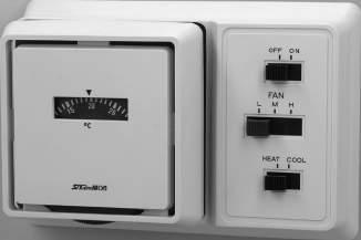
37 ROOM THERMOSTATS
GENERAL DESCRIPTION • For fan coil units and air conditioners. • Used for low or line voltage. • Various models available with Fan Selector switch and/or Heat-Off-Cool change over switching. • Using a diaphragm element, it assures high reliability and accurate control. • Ambient temperature: 20 to 50°C TYPE NUMBER SELECTION (SPECIFICATIONS) ELECTRICAL RATINGS Minimum contact capacity: 50mA ・ Change over switch of HEAT–COOL on WRS–C130X1 is only for changing switch mechanism of room thermostat itself between HIGHCUT (HEATING) and LOWCUT (COOLING) according to system requirement. Please refer to the application sample and wiring diagram. Unit: °C CONTACT FUNCTIONS DIMENSIONS HEAT L M H COOL OFF ON ℃ 20 1525 90 133 42 15 Base 19 20 20 System Switches Unit: mm Catalog No. Sub-Base Function Range Differential Wt. (kg)Type Contact & Temp. Range Special Application Change over Switch Fan Switch Min. Max. WRS– C130 X1 ON–OFF, HEAT–COOL HIGH–MED–LOW 10 30 Approx. 1.5 (Fixed) X20.25 ON–OFF X7 ON–OFF, HEAT–COOL Rated Voltage (V) Rated Current (A) Power Factor (cosφ) 125V AC 250V AC Non-Inductive Current 1 6 3 Inductive Current Full Load 0.75 Inrush Current 24 12 Type WRS–C130X1 WRS–C130X2 WRS–C130X7 Inter nal Wiring Arrow indicates temp. rise. TO FAN SPEED CONTROL OFF HIGH MED. LOW ON TEMP. RISE HEAT COOL TO MOTOR VALVE L1 ON OFF L H C YELLOW BLACK BLUE GRAY ORANGE TO FAN SPEED CONTROL TO COOLING CONTROL TO HEATING CONTROL OFF HIGH MED. LOW TEMP. RISE L1 ON OFF L C H YELLOW BLACK BLUE ORANGE BROWN RED TO FAN SPEED CONTROL OFF ON TEMP. RISE HEAT COOL HEAT COOL L1 TO HEATING CONTROL TO COOLING CONTROL ON OFF L C H YELLOW BLACK BLUE GRAY WHITE ORANGE HIGH MED. LOW Correo: xbombas@gmail.com Telefono: 55 5378 7190

38 Minimum Contact Capacity: 50mA ROOM HUMIDISTATS Type AHS GENERAL DESCRIPTION • Accurate humidity control assured by nylon ribbon. • Used for low or line voltage. • Easy adjustment by dial knob. • Dial stopper screw prevents unauthorized change of setting. SPECIFICATIONS ELECTRICAL RATINGS DIMENSIONS 80 90 39.534 □76 Cover Body Sub-Base Adjusting Dial Knob □68 CONTACT FUNCTIONS Internal Wiring Application and Wiring Examples H H C L C L H C L Relay etc. for Dehumidifying Equipment Power Power Humidifying DehumidifyingControl Control Solenoid Valve, Relay etc. for Humidifying Equipment Arrow mark indicates humidity increase. Unit: % RH Unit: mm Catalog No. Contact Range Differential Ambient Temp. on Use (°C) Wt. Min(kg) Max. AHS–C1090 SPDT 30 90 Approx. 5 10 to 40 0.17 Rated Voltage (V) Rated Current (A) Power Factor (cosφ) 125V AC 250V AC 24V DC Non-Inductive Current 1.0 4.5 2 1 Inductive Current Full Load 0.75 3 1.5 0.4 Inrush Current 12 6 2 Correo: xbombas@gmail.com Telefono: 55 5378 7190
& DIGITAL HUMIDISTATS
Type ALE & BLE
GENERAL DESCRIPTION
TYPE NUMBER SELECTION (SPECIFICATIONS)
Type ALE Digital Thermostats
ALE–SD11–011
ALE–SD12–011
ALE–SD13–011
ALE–SD14–011
ALE–SD15–011
ALE–SD22–011
ALE–SD23–011
ALE–SD24–011
ALE–SD25–011
Type BLE Digital humidistats
BLE–SD11–011
Type ALE Digital thermostats


Step
Step)
TEK–83H609 (with 2m lead)
Step)
TEK–83H601 (with 2m lead)
39 DIGITAL THERMOSTATS
• LCD with high brightness backlight • Power supply voltage: 85 to 264V.AC 50/60Hz • Forced ON/OFF • Relay output: 250V AC , 10A (cosφ=1) 6A (cosφ=0.7) 3A (cosφ=0.4) • Ambient temperature: Controller 10 to 50°C • Type ALE: ・Available 0.1°C pitch display (select 0.1°C / 0.5°C / 1°C) ・Max.4 ON/OFF points during 24 hours model available. ・MODBUS communication • Type BLE: ・Setting in each 1%RH is possible. ・Ambient temperature: Humidity sensor 0 to 50°C Type BLEType ALE
・ Temperature sensor type TEK–83H609 or TEK–83H601 and sensor holder are supplied as standard accessories. Enclosure IP44(Front of products) Unit: °C Catalog No. Temp. Set Range Differential Temp. Indication Function Sensor Part No. (Standard) Wt. (kg)
50 to 30 Min. 0.5 55 to 40 Standard(1
0.2
2 Step
1 Step + Hi/Lo limit with time delay
1 Step + Programmable
2 Step + Programmable ALE–SD21–011 0 to 100 0 to 110 Standard(1
2 Step
1 Step + Hi/Lo limit with time delay
1
+ Programmable
2 Step + Programmable
Unit: %RH Catalog No. Humidity Set Range Differential Humidity Indication Calibration Function Sensor Part No. (Standard) Wt. (kg)
30 to 90 Min. 3 20 to 99 ±10 1 Step HEK–I1R001 0.3 BLE–SD11–011 2 Step Humidity sensor type HEK–I1R001 is supplied as standard accessory ・ Enclosure IP44(Front of products) OPERATION 2 Step model (Cooling Mode) On Off OnOff On Temp. (Set Point) Off On Off Operation Operation (Floating Mode) On Off OnOff On Temp. (Set Point) Off On Off Operation (Heating Mode) On Off OnOff On Temp. (Set Point) Off On Off Min. 0.5℃ Min. 0.5℃ Min. 0.5℃ Min. 0.5℃ Min. 0.5℃ Min. 0.5℃ or 6 7 Terminal 8 9 or 8 9 Terminal 6 7 or Terminal 8 9 or 8 9 Terminal 6 7 6 7 or 6 7 Terminal 8 9 or 8 9 Terminal 6 7
Standard (1 Step) model (Cooling Mode) On Min. 0.5℃ Off On Temp. (Set Point) TerminalOff Operation 6 7 (Heating Mode) On Min. 0.5℃ OnOff Temp. (Set Point) TerminalOff Operation 6 7 ・ Free to set On/Off set point independently within the range. ・ When Off set point is changed, On set point automatically shifts. (Diff. remains same) ・ When On set point is changed, Off set point remains unchanged. (Diff. changes) Correo: xbombas@gmail.com Telefono: 55 5378 7190
1 Step + Programmable model
Operation
・ Free to set On/Off set point independently within the range.
2 Step + Programmable model
Please check the 2Step model
・ When Off set point is changed, On set point automatically shifts. (Diff. remains same)
set point
point
・ When On set point is changed, Off set point remains unchanged. (Diff. changes)
Programmable
Programmable function
Max. 4 ON/OFF points during 24 hours model available.
・Change the set temperature (ON / OFF) at the specified time.
Change the set temperature
・Stop the control at the specified time.
the control
[Program example 1]
[Program example 1]
Change the set temperature four times a day at the specified time.
temperature
Item1:6:00 OFF 6℃ / ON 9℃
Item1:6:00
Item2:9:00 OFF 5℃ / ON 7℃
Item2:9:00
Item3:18:00 OFF 6℃ / ON 10℃
Item3:18:00
Item4:21:00 OFF 8℃ / ON 12℃
This program performs the following operations.
Type BLE Digital humidistats
Standard (1 Step) model
When
・
[Program example 2]
[Program example 2]
Stop control in the night (20:00 to 5:00)
Stop control in the night (20:00 to 5:00)
Item1:5:00 OFF 6℃ / ON 9℃
Item1:5:00 OFF 6°C / ON 9°C
Item2:20:00 OFF 5℃ / ON 7℃
Item2:20:00 OFF 5°C / ON 7°C
This program performs the following operations.
This program performs the following operations.
Stop control
※This model can combine the settings of program example 1 and 2.
In this case also a combination of up to 4 points within 24 hours.
set On/Off set point independently
On/Off set point
set point
changed,
Off set point is changed,
set point automatically shifts. (Diff.
same)
point
When On set point is changed,
set point remains unchanged.
40 1 Step + Hi/Lo limit with time delay model On LoOff Limit Hi OnLimit Temp. (Set Point) Off On Off Terminal Operation 8 9 Terminal 6 7 Lo limit setting range Lo Limit Time Set (Lo limit Func starts after 0 to 120 min. ) Hi Limit Time Set (Hi limit Func starts after 0 to 120 min. ) Hi limit setting Min.range 0.5℃ On LoOn Limit Hi OffLimit Temp. (Set Point) Off On Off Terminal Operation 8 9 Terminal 6 7 Lo limit setting range Lo Limit Time Set (Lo limit Func starts after 0 to 120 min. ) Hi Limit Time Set (Hi limit Func starts after 0 to 120 min. ) Hi limit setting Min.range 0.5℃ Hi/Lo limit output is reset manualy (Push reset: Push ENT Key in 2 sec or power off) ・ Delay Timer can be set in the time range from 0 to 120 min respectively. Min. 0.5℃ Off On On Off Min. 0.5℃ 1 Step + Programmable model Off On 12:0 0 18:0 0 24:0 0 1 234 5℃ 7℃ 6℃ 12℃ 8℃ 6℃ 12℃ 6:0 00 :0 0 8℃ 9℃ 10℃ 10℃ On 6℃ Off 1 2 12:0 0 18:0 0 24:0 60 :0 00 :0 0 Stop control
function Max. 4 ON/OFF points during 24 hours model available
OFF 6°C / ON 9°C
OFF 5°C / ON 7°C
OFF 6°C / ON 10°C Item4:21:00 OFF 8°C / ON 12°C This program performs the following operations. ※This model can combine the settings of program example 1 and 2. In this case also a combination of up to 4 points within 24 hours. Temp. (Set Point) Temp. (Set Point)
Change the set
four times a day at the specified time.
Min. 3%RH Type BLE Digital humidistats Standard (1 Step) model
(ON / OFF) at the specified time. Stop
at the specified time.
Operation (Dehumidity Mode) (Humidity Mode) (Cooling Mode) (Heating Mode) Terminal 6 7 Off On Off On Off On On Off (Set Point) (Set Point) Operation Operation Terminal 6 7 Off On Off On Min. 3%RH Humidity Humidity Free to set On/Off set point independently within the range. ・ When Off
is changed, On set point automatically shifts. (Diff. remains same) ・ When On set
is changed, Off set point remains unchanged. (Diff. changes) ・ Free to set
independently within the range.
Off
is
On set point automatically shifts. (Diff. remains same) When On set
is changed, Off set point remains unchanged. (Diff. changes) 2 Terminal 6 7 Terminal 6 7 1 Step + Hi/Lo limit with time delay model ・ Free to
within the range.
When
On
remains
Off
(Diff. changes)
output (Push power off)
Correo: xbombas@gmail.com Telefono: 55 5378 7190
TEK–83H609 (Temperature)
TEK–83H609
TEK–83H601 (Temperature)
temp.
temp.
the sensor
usage: 55 to 80°C
in
under
dripping
outdoor,
of dew, water dripping or outdoor,
holder
temp.
temp.
be vertically installed with
vertically
as standa
to
41 Sensor Part No. Applicable Model Dimension Remarks
ALE–SD11–011 ALE–SD12–011 ALE–SD13–011 ALE–SD14–011 ALE–SD15–011 • Ambient
on
• When
is
use
the condition
the sensor should
lead wire outlet downward. • Sensor holder is supplied as standard. Lead Wire:Blue
ALE–SD21–011 ALE–SD22–011 ALE–SD23–011 ALE–SD24–011 ALE–SD25–011 • Ambient
on usage: 40
110°C • When the sensor is in use under the condition of dew, water dripping or outdoor, the sensor should be vertically installed with lead wire outlet downward. • Sensor holder is supplied as standard. Lead Wire:Black HEK–I1R001 (Humidity) BLE–SD11–011 BLE–SD12–011 • Designed to accord room interior • Designed to be installed where certain air flow runs and the room humidity is represented. • Depending on load or other conditions, humidity control may become difficult. ACCESSORIES 302000 6φ Sensor Holder 18 52 13 2 φ4.2 27 15 Following sensors are available as option. (Ambient temperature sensors are available upon request.) Direct immersion sensor with nipple TEK–83N Wall mounting sensor TEK–83R Surface temp. sensor TEK–83E Direct immersion sensor with terminal coverr TEK–83B Bulb well TEK–00N 102 105 83.5 71 33 Elliptic Holes φ4.5 Sensor Mounting Bracket 3 Unit: mm Unit: mm 6 7 8 9 Relay Contact 1 Relay Contact 2 Load Load Power Supply for Load Power Supply for Load On Off On Off On (Set Point) Off On Off Terminal or or On On Off On Off Off On Off On On Off Off On Off On Off Terminal or or Terminal or or 2 Step model (Dehumidity Mode) (Floating (Mode) Humidity Mode) Terminal Humidity (Set Point) Humidity (Set Point) HumidityTerminal 1 2 3 4 5 6 7 8 9 Relay Contact 1 Relay Contact 2 SensorLoad Load Power Supply for Load Power Supply for PowerLoad Supply 85 to 264V.AC 1 2 3 1 2 3 4 5 Power Supply 85 to 264V.AC Sensor (Type HEK) 6 7 (Control output): WIRING DIAGRAM Type ALE Type BLE 8 9 (Alarm output) (Control output): 6 7 (Control output): 8 9 (Control output): ACCESSORIES Following sensors are available as option. (Ambient temperature sensors are available upon request.) Operation Operation OperationMin. 3%RH Standard (1 Step) model, 2 Step model, 1 Step model + Hi/Lo limit with time delay model, and 1 Step model + Programmable model 2 Step model 1 Step model + Hi/Lo limit with time delay model Standard (1 Step) model and 2 Step model 2 Step model Terminal : Sensor Part No. Applicable Model Dimension Remarks TEK–83H601 (Temperature) ALE–SD21–011 ALE–SD22–011 ALE–SD23–011 ALE–SD24–011 • Ambient
on usage: 40 to 110°C • When the sensor is in use under the condition of dew, water
or
sensor
lead wire outlet downward. • Sensor
is supplied
rd. Lead Wire:Black
(Temperature) ALE–SD11–011 ALE–SD12–011 ALE–SD13–011 ALE–SD14–011 • Ambient
on usage: 55 to 80°C • When the sensor is in use under the condition of dew, water dripping or outdoor, the sensor should be vertically installed with lead wire outlet downward. • Sensor holder is supplied as standard. Lead Wire:Blue HEK–I1R001 (Humidity) BLE–SD11–011 BLE–SD12–011 • Designed to accord room interior • Designed to be installed where certain air ow runs and the room humidity is represented. • Depending on load or other conditions, humidity control may become dif cult. 302000 6φ Sensor Holder 102 105 83.5 71 33 Elliptic Holes φ4.5 Sensor Mounting Bracket 3 18 52 13 2 φ4.2 27 15 Direct immersion sensor with nipple TEK–83N Wall mounting sensor TEK–83R Surface temp. sensor TEK–83E Direct immersion sensor with terminal cover TEK–83B Bulb well TEK–00N Unit : mm Unit : mm 6 7 6 7 8 9 8 9 6 7 6 7 8 9 8 9 6 7 6 7 8 9 8 9 3 Min. 3%RH Min. 3%RH Min. 3%RH Min. 3%RH Min. 3%RH 2 Step model WIRING DIAGRAM 6 7 :(Control output) :Standard (1 Step) model, 2 Step model, 1 Step model + Hi/Lo limit with time delay model, and 1 Step model + Programmable model 8 9 :(Control output) :2 Step model (Alarm output) :1 Step model + Hi/Lo limit with time delay model :(Control output):Standard (1 Step) model and 2 Step model 8 9 :(Control output):2 Step model Type ALE Type BLE Correo: xbombas@gmail.com Telefono: 55 5378 7190
42 83 127 11 Gasket Front Panel SEL ENT 122 77 COOL HEAT OFF ON SET ON 16 10.544 54.5 71+1-0.5 1727 50 50 26 1 16 +1 -0.5 DIMENSIONS Type ALE, BLE OPERATION Type ALE-AA02 Panel Mount Bracket including Gasket Wall Mount Installation Dimension Panel Cut Dimension Unit: mm Unit: mm Communication function Type ALE This product allows the following operations using the communication function. Saginomiya Seisakusho's monitoring software allows the following checks and operations on the PC. • Monitoring current temperature • Checking current settings • Switching operation mode (COOL/HEAT) • Registering program • Setting time • Saving measurement data • Monitoring output ON/OFF • Setting OFF/ON setting values • Setting calibration • Enabling/disabling program function • Locking/unlocking key The following shows a summary of communication specifications. * You need to provide an RS-485 communication converter and a communication cable required for communication. * Please download the monitoring software from the saginomiya website. (Free of charge) * For details on communication specifications, contact your dealer or Saginomiya Seisakusho. Interface : IRS-485 Connection method : Two-wire half-duplex multi-drop connection ・ Number of connected units : 16 or less ・ Protocol : Modbus Transmission mode : Remote Terminal Unit (RTU) Correo: xbombas@gmail.com Telefono: 55 5378 7190
Type

43 DIGITAL THERMOSTATS
TNE GENERAL DESCRIPTION • Compact digital temperature controller (48mm×48mm) for many applications. • H i g h q u a l i t y t e m p e r a t u r e c o n t r o l w i t h p l a t i n u m a n d thermo couple temperature sensor (option). • Two kinds of output current output and relay output are available. • Various function such as PID Control, Auto/Manual Changeover and Lock Function are installed. • Two points output for High/Low limit alarm. • Power supply voltage: 100 to 240 V.AC 50/60Hz • Adaptive temperature sensor: Pt100, JPt100 Thermocouple (Type K, J, R, T, N, S, B) TYPE NUMBER SELECTION (SPECIFICATIONS) WIRING DIAGRAM DIMENSIONS MOUNTING SIZE 1 2 3 4 5 6 11 12 13 14 15 Fuse Power Supply Power Supply for Load Power Supply for Load B b A Platinum Temperature Sensor Thermocouple Temperature Sensor LoadLoad OUT1 AL2 AL1 1 2 3 4 5 6 11 12 13 14 15 Fuse Power Supply Power Supply for Load Power Supply for Load B b A Platinum Temperature Sensor Thermocouple Temperature Sensor LoadLoad OUT1 AL2 AL1 or or NO C TNE SNPR N21 Relay Output Current Output TNE SNPA N21 + + + Panel(thickness:under 5mm) 2 48 48 677 Packing ℃ MODEFUNC AL1 AL2 RDY PV SV OUT1 • Indicator: Temperature 7Seg. Green LED 4 digits Temperature set point 7Seg. Red LED 4 digits Control output Red LED×3 Unit: mm Panel Cutout Size OPTIONAL PARTS Platinum Temperature Sensor (Type: PEK–02H001) + 0.6 -0 45-0 +0.6 45 48 or over 60 or over White White Red 50 503000 SUS Cap. Lead Wire4.8φ b B A ACCESSORY Fixing Bracket Catalog No. Temp. Set Range Control Type Control Output Alarm Output (Relay) Wt. (kg) TNE–SNPR–N21 based on a connection sensor On/Off Relay (SPST 250V.AC 3A) SPST 250V.AC 2A×2 0.18 TNE–SNPA–N21 PID (Self tuning) Current (4 to 20 mA DC) Ambient temperature 0 to 50℃ Temperature range: 70 to 140℃ Resistance value: 100Ω(0℃) Correo: xbombas@gmail.com Telefono: 55 5378 7190
CONNECTION & ACCESSORIES 45–47 DRIP PROOF & WATER PROOF CONTROLS 48–53 Series NS–W & NS–P PRESSURE &TEMPERA TURE CONTROLS INFORMA TION PRESSURE &TEMPERATURE CONTROLS INFORMATION Correo: xbombas@gmail.com Telefono: 55 5378 7190
ONS PROTECTION CONTROLS
45 CONNECTION & ACCESSORIES NS PRESSURE CONTROLS NOMENCLATURE Catalog No. is decided according to the specifications. M1 N W G Q Ⅰ Ⅱ Ⅲ Ⅳ Example: HNS C1 30 X Ⅰ N=SUS Bellows Ⅱ W=Drip Proof, P=Water Proof (Except for Type HNS, WNS, YNS) Ⅲ Connection Style.... Refer to Connection Table Below Ⅳ Option....Special No.
NOMENCLATURE Catalog No. is decided according to the specifications. N W G Q ⅠⅡ Ⅲ Ⅳ Example: ONS C1 06 X Ⅰ N=SUS Bellows Ⅱ W=Drip Proof Ⅲ Connection Style.... Refer to Connection Table Below Ⅳ Timer Speci cation.... Q1~Q12、Q25~Q36 Connection Table (for NS Series Pressure Controls ) Size Connection Style Copper Steel 1/4" φ8 3/8" φ10 1/2" φ10.5 B Flare Except Below (Stand.) B1 B2 B3 B4 ANS B B1 B2 B3 B4 U Union U1 U2 U (Stand.) U3 G Female Thread Rc G (Stand.) G3 G6 G G1 G4 G7 NPT G2 G5 G8 M Male Thread Except Below R M02 M01 (Stand.) M07 G M03 M05 M08 NPT M04 M06 M09 ANS R M1 M (Stand.) M6 G M2 M4 M7 NPT M3 M5 M8 K Flareless Direct K1 K2 K (Stand.) Connector K3 Size Connection Style 1000 mm 2000 mm L Capillary L1 (Stand.) L2 Correo: xbombas@gmail.com Telefono: 55 5378 7190
Capillary
Size A B C
Rc1/4
23G1/4
NPT
Rc3/8
23G3/8 3/8 NPT
Rc1/2
27G1/2
Size A B C
1/4" R1/4
29G1/4
NPT
R3/8
29G3/8 3/8 NPT
R1/2
33G1/2
NPT
Type L
46 NS TEMPERATURE CONTROLS NOMENCLATURE Catalog No. is decided according to the specifications. Example: TNS C1 100 X M2 W L1 Q1 Ⅰ Ⅱ Ⅲ Ⅰ W=Drip Proof, P=Water Proof Ⅱ Connection Style.... Refer to Connection Table Below Ⅲ Option....Special No.
Length Table * TNS–C1010XC to TNS–C1070XC: Capillary length are 1m to 5m Size Connection Style Normal Nickel Plated Except BNS BNS Except BNS BNS 1m Standard L1 Q012 L1Q012 2m L2 L2Q012 3m L3 L3Q012 5m L5 L5Q012 7m L7 L7Q012 10m L0 L0Q012 Except Above LQ LZ LQ012 LZQ012 (B) Flare (U) Union Pipe Thread (G) Female (M) Male (K) Flareless Type Connection (L) Capillary Copper Pipe (Direct) Steel Pipe (Connector Option) K3 Size A B C D E F G φ1/4 φ6.5 17 12 7/16–20 UNF 0 20.5 26 φ8 φ8.2 22 17 5/8–18 UNF 5 24.5 36φ3/8 φ9.7 φ10 φ10.2 φ1/2 φ12.9 24 22 3/4–16 UNF 5 27.5 40 Size A B C D E F φ6 6.2 14 14 M12 23 33 φ8 8.2 17 14 M14 23 33 φ10 10.2 19 17 M16 23 34
L1 1000 L2 2000
1/4"
19
1/4
3/8"
22
1/2"
27
1/2 NPT
17
1/4
3/8"
19
1/2"
22
1/2
Size A φ6 Copper φ6.5 φ8 Copper φ8.5 φ10 Copper φ10.5 φ10.5 Steel φ11.0 Connection Dimension Table Hex. C A Hex. B (G)D E F Hex. 22 Hex. 30 A 5 4027 A Hex. B C A Hex.B C A Hex.B Hex.C D Thread (F) E (60.5)(48.5) 10.7 Hex.19 M16 Hex.17 G Connection 1/4" Flare Nut φ2.4 ×L Capillary Tube Unit: mm Correo: xbombas@gmail.com Telefono: 55 5378 7190
SNS–AE01
YS, NS, FE Series
BLS
ALS, BLS ALS–AE09
PWS (Except PWS-7060) LWS–AE12SNS–AE11
NS
Controls Catalog No.
TNS–C100 to C134
CNS–C115 (M2) to C134 (M2)
1/2" TNS–AB01
63/4" TNS–AB09
Controls Catalog No. Size Parts No. Size C×FCopper SUS
TNS–C100 to C134 CNS–C115 (M2) to C134 (M2) 1/2" TNS–AC01 TNS–AC46 φ8×953/4" TNS–AC35 TNS–AC56
WS
LS
TNS–C1070
TNS–C1010C to C1070C 1/2" TNS–AB04
12.73/4" TNS–AB07
TNS–C1100 to C1150 1/2" TNS–AB17
12.7 Heat Proof3/4" TNS–AB18
INS–C1070M1 1/2" TNS–AB02
9.53/4" TNS–AB05
INS–C1120M1, C1150M1 1/2" TNS–AB15
9.5 Heat Proof3/4" TNS–AB16
NS
TNS–C1070 to C1150 TNS–C1010C to C1070C
1/2" TNS–AC05 TNS–AC12 φ15×115 3/4" TNS–AC09 TNS–AC14
INS–C1070M1 to C1150M1 1/2" TNS–AC02 TNS–AC11 φ12×953/4" TNS–AC06 TNS–AC13
LWS–C1030 to C1090 1/2" LWS–AC15 LWS–AC21 φ12×1103/4" LWS–AC17 LWS–AC23
LWS–C1030 to C1094
PWS–7034 to 7094 1/2" LWS–AB02
9.53/4" LWS–AB05
LWS–C1120 to C1240 PWS–7120 1/2" LWS–AB15
9.5 Heat Proof3/4" LWS–AB16
ALS–C1011 to C1050 BLS–C1020 1/2" ALS–AB03
103/4" ALS–AB06
ALS–C1090 1/2" ALS–AB10
WS
10
Proof
LWS–C1120 to 1160 PWS–7120 1/2" LWS–AC19 LWS–AC25
12×803/4" LWS–AC20 LWS–AC26
LWS–C1200 to C1240 1/2" LWS–AC48 LWS–AC50
12×80 Heat Proof3/4" LWS–AC49 LWS–AC51
LWS–C1034 to C1094 PWS–7034 to 7094 1/2" LWS–AC16 LWS–AC22
12×1403/4" LWS–AC18 LWS–AC24
EWS–C1080 to C1160 1/2" EWS–AC27
ALS–C1011
3/4"
ALS–AC03 ALS–AC36
10.8
12
75
70 EWS–AC28
Name Body Bracket Bulb Bracket Type Parts No. Type Parts No. Type Parts No. Type Parts No.
(Standard Acce.) NS Series SNS–AE02 LWS FWS RWS LWS–AE08
LWS
ALS, BLS ALS–AE02 ALS,
ALS–AE01 Form Size Max Press. Torque A B D E 1/2" Static Press. 1MPa 12N・m or less Hex. 24 Hex. 22 R1/2 (43) 3/4" Hex. 32 Hex. 30 R3/4 (54)
Size Parts No. Size C
φ
φ
φ
φ
φ
φ
φ
φ
φ
Heat
φ
φ
φ
φ
×
φ
×
LS
to C1090 BLS–C1020 1/2"
φ12×105
ALS–AC07 Size Max Press. Torque A B D E 1/2" Static Press. 3MPa 12N・m or less Hex. 24 R1/2 10 20 3/4" Hex. 24 R3/4 10 22 47 27 25 (12.5) 11.5 55.2 20 20 1010 R3.560 7 2 40 25 4 φ4.4 7.5 8 25 47 (85) 2 82 (120) 7.5 30 95 65 30 25 7 20 40 5 25 8 φ4.4 20 25 12 6 7 2 4 φ5.5 6 6 10 86 74 16 31 50 80 40 15 3 M3×0.5 2 φ6.2 61 20 20 8 6575 2 φ4.4 φ9 Insert Holder, Protect Tube (For Temperature Controls) Insert Holder Protect Tube Insert Holder Protect Tube E B AD C D E F AC B M5 Distance Piece Protect Tube Bulb ACCESSORIES Mounting Brackets ( ) SNS–AE11 Ambient temp.: 40 to 90℃ Correo: xbombas@gmail.com Telefono: 55 5378 7190
DRIP PROOF & WATER PROOF CONTROLS
SERIES NS–W & NS–P
GENERAL DESCRIPTION
Standard gland size:
standard gland
No.
Type SNS–C106XW
SNS–C106XP
Type SNS–W/P
proof
Water proof model of single function pressure controls.

TYPE NUMBER SELECTION (SPECIFICATIONS)
Automatic reset type
SNS–C101X W 0.06 { 50cmHg} 0.1
0.015
0.025 {0.25} 0.05 {0.5} 0.3 {3}
SNS–C102X W, P 0.02 { 20cmHg} 0.2 {2} 0.025 {0.25} 0.15 {1.5} 0.5 {5}
SNS–C103X W, P 0.06 { 50cmHg} 0.3 {3} 0.035 {0.35} 0.2 {2} 0.05 {0.5} 0.15 {1.5} 1 {10}
Unit: MPa {kgf/cm2}
SNS–C104X W, P 0.06 { 50cmHg} 0.4 {4} 0.04 {0.4} 0.1 {1} 0.2 {2} 1.5 {15}
Diagram 1
SNS–C106X W, P 0.06 { 50cmHg} 0.6 {6} 0.06 {0.6} 0.4 {4} 0.2 {2} 0.3 {3}
SNS–C110X W, P 0.1 {1} 1 {10} 0.1 {1} 0.3 {3} 0.4 {4} 0.6 {6}
SNS–C130X W, P 0.5 {5} 3 {30} 0.3 {3} 1 {10} 2 {20} 2.5 {25} 3.3 {33}
SNS–C135X W, P 1 {10} 3.5 {35} 0.5 {5} 1.5 {15} 2.5 {25} 3 {30} 3.8 {38}
SNS–W: Approx. 1.1 SNS–P: Approx. 0.6
Manual reset type Unit: MPa {kgf/cm2}

Setting
Contact
SNS–C102XM2
Catalog No. Range Manual Reset Factory
Max. Working Pressure
Function Wt. (kg) Min. Max. Off (On) On (Off)
W, P 0.02{ 20cmHg} 0.2 {2} Automatic operation on pressure decrease and manual reset on pressure increase 0.025 {0.25} Manual Reset 0.5 {5} Diagram 2 SNS–W: Approx. 1.1 SNS–P: Approx. 0.6 SNS–C106XM2 W, P 0.06{ 50cmHg} 0.6 {6} 0.2 {2} 1.5 {15} SNS–C130XM2 W, P 0.5 {5} 3 {30} 2 {20} 3.3 {33} 48
• Approved by various marine standards such as Bureau Veritas, Lioyd's Register, Det Norske Veritas ∙ Germanischer Lioyd's, Nippon Kaiji Kyokai, ABS etc. • Suitable for indoor or outdoor applications where water drips and dusts ar e apt to enter, such as marine refrigeration units or industrial plants. • External wiring is made by cabtyre cable connection with cable glands.
φ20mm Semi
size: φ15mm • To order, specify catalog
with “W” or “P”. Example:
Drip proof model Type
Water proof model
Type SNS–W, FNS–W, ANS–W
Type SNS–P, FNS–P, ANS–P
●
Drip
and
* Based on the 1–3 terminal connection. * Catalog No. Range Differential Factory Setting Max. Working Pressure Contact Function Wt. (kg) Min. Max. Min. Max. Off (On) On (Off)
{1}
{0.15} 0.05 {0.5}
ELECTRICAL RATINGS CONTACT FUNCTIONS 1 5 3 1 5 3 1 3 5 1 3 M15 M2 Diagram 1 Diagram 2 ↑ : Operating direction on press. increase at High Press. Side M2 ↑ : Operating direction on manual reset Rated Voltage (V) Rated Current (A) Power Factor (cosφ) 125/250V AC Non-Inductive Current 1 12 Inductive Current Full Load 0.75 Inrush Current 72 Diagram 1 & 2 1 Common Terminal 3 Close on Pressure Increase 5 Close on Pressure Decrease Minimum contact capacity: 50mA Correo: xbombas@gmail.com Telefono: 55 5378 7190
Type DNS–W/P Drip proof and Water proof model of
function pressure controls
TYPE NUMBER SELECTION (SPECIFICATIONS)
Automatic reset type Unit: MPa {kgf/cm2}


Catalog No. Pressure Side Range
DNS–D304X W, P
DNS–D306X W, P
DNS–D604X W, P
DNS–D606X W, P
Factory Setting Max. Working Pressure Contact Function Wt. (kg) Min. Max. Min. Max. Off On
Low Side 0.06 { 50cmHg} 0.4 {6} 0.04 {0.4} 0.2 {2} 0.1 {1} 0.2 {2} 1.5 {15}
High Side 0.8 {8} 3 {30} Approx. 0.4 fixed. {Approx. 4 fixed.} 2 {20} 1.6 {16} 3.3 {33}
Low Side 0.06 { 50cmHg} 0.6 {6} 0.06 {0.6} 0.4 {4} 0.2 {2} 0.3 {3} 1.5 {15}
High Side 0.8 {8} 3 {30} Approx. 0.4 fixed. {Approx. 4 fixed.} 2 {20} 1.6 {16} 3.3 {33}
Low Side 0.06 { 50cmHg} 0.4 {6} 0.04 {0.4} 0.2 {2} 0.1 {1} 0.2 {2} 1.5 {15}
High Side 0.8 {8} 3 {30} Approx. 0.4 fixed. {Approx. 4 fixed.} 2 {20} 1.6 {16} 3.3 {33}
Low Side 0.06 { 50cmHg} 0.6 {6} 0.06 {0.6} 0.4 {4} 0.2 {2} 0.3 {3} 1.5 {15} High Side 0.8 {8} 3 {30} Approx. 0.4 fixed. {Approx. 4 fixed.} 2 {20} 1.6 {16} 3.3 {33}
Diagram 3 DNS–W: Approx. 1.4 DNS–P: Approx. 0.9
Diagram 5
Manual reset type Unit: MPa {kgf/cm2} Catalog No. Pressure Side Range Differential
DNS–D304XM W, P
DNS–D306XM W, P
DNS–D604XM
Factory Setting Max. Working Pressure Contact Function Wt. (kg) Min. Max. Min. Max. Off On
Low Side 0.06 { 50cmHg} 0.4
High Side
Low Side
Diagram
DNS–W: Approx. 1.4
DNS–P: Approx. 0.9
49 DIMENSIONS 11.5 (51) 88 80 10 (63) 3 28 28 8 20 7 150 18 20 18 29 67 67 (24) Conduit Gland Flare Nut 110 9 (88) 1 1 33 37.5 98 114 8 8 6 (65.5) 37.5 Conduit Gland Flare Nut Unit: mm Type SNS–P, FNS–P, ANS–P Type SNS–W, FNS–W, ANS–W ●
dual
Type DNS–W
Type
DNS–P
Differential
{4} 0.04 {0.4} 0.2 {2} 0.1 {1} 0.2 {2} 1.5 {15}
4
0.8 {8} 3 {30} Automatic operation on pressure increase and manual reset on pressure decrease 2 {20} manual reset 3.3 {33}
0.06{ 50cmHg} 0.4 {4} 0.06 {0.6} 0.4 {4} 0.2 {2} 0.3 {3} 1.5 {15} High Side 0.8 {8} 3 {30} Automatic operation on pressure increase and manual reset on pressure decrease 2 {20} manual reset 3.3 {33}
W, P Low Side 0.06{ 50cmHg} 0.4 {4} 0.04 {0.4} 0.2 {2} 0.1 {1} 0.2 {2} 1.5 {15} Diagram 6 High Side 0.8 {8} 3 {30} Automatic operation on pressure increase and manual reset on pressure decrease 2 {20} manual reset 3.3 {33} DNS–D606XM W, P Low Side 0.06{ 50cmHg} 0.6 {6} 0.06 {0.6} 0.4 {4} 0.2 {2} 0.3 {3} 1.5 {15} High Side 0.8 {8} 3 {30} Automatic operation on pressure increase and manual reset on pressure decrease 2 {20} manual reset 3.3 {33} DNS–D606XMM W Low Side 0.06{ 50cmHg} 0.6 {6} Automatic operation on pressure decrease and manual reset on pressure increase 0.2 {2} manual reset 1.5 {15} Diagram 7 High Side 0.8 {8} 3 {30} Automatic operation on pressure increase and manual reset on pressure decrease 2 {20} 3.3 {33} Correo: xbombas@gmail.com Telefono: 55 5378 7190

50 Unit: mm CONTACT FUNCTIONS 1 4 2H L 3 1 4 H M 2 L 3 1 54 26 H L 3 1 54 26 H M L 3 1 54 26 H M L M 3 L ↓ : Operating direction on press. increase at Low Press. Side H ↑ : Operating direction on press. increase at High Press. Side M↓ : Operating direction on manual reset Diagram 3 Diagram 4 Diagram 5 Diagram 6 Diagram 7 ELECTRICAL RATINGS Rated Voltage (V) Rated Current (A) Power Factor (cosφ) 125/250V AC Non-Inductive Current 1 12 Inductive Current Full Load 0.75 Inrush Current 72 DIMENSIONS Type DNS–P Type DNS–W 11.5 (51) Conduit Gland 88 80 (99) 10 (20.5) (63) 3 23 28 28 8 20 7 63 192 18 24 18 88 88 29 111 137 31 35 7.5 7.5 (61) 120 135 28 9 (90) 1 1 6 27.5 32.5 40 Conduit(65) Gland Flare Nut Reset Button ● Type HNS–W Drip proof model of single function hight pressure controls Catalog No. Range Differential Factory Setting Max. Working Pressure Wt. (kg) Min. Max. Off On HNS–C130X W 0.8 {8} 3 {30} 0.3 to 0.5 Fixed {3 to 5 fixed} 2 {20} 1.6 {16} 3.3 {33} Approx. 1.1 Catalog No. Range Manual Reset Factory Setting Max. Working Pressure Wt. (kg) Min. Max. Off On HNS–C130XM1 W 0.8 {8} 3 {30} Automatic operation on pressure increase and manual reset on pressure decrease 2 {20} manual reset 3.3 {33} Approx. 1.1 TYPE NUMBER SELECTION (SPECIFICATIONS) Automatic reset type Unit: MPa {kgf/cm2} For specifications, electrical ratings, and contact functions, refer to page 13, 14. For specifications, electrical ratings, and contact functions, refer to page 13, 14. Manual reset type Unit: MPa {kgf/cm2} * * HNS–W Correo: xbombas@gmail.com Telefono: 55 5378 7190
FNS–W, ANS–W
TYPE NUMBER SELECTION (SPECIFICATIONS)
Catalog No. Range Differential
Unit: MPa {kgf/cm2}
Factory Setting Max. Working Pressure Wt. (kg) Min. Max. Fixed Off On
FNS–C1**X W, P 0.06 { 50cmHg} to 0.5 {5}
Catalog
0.1 {1} to 3 {30}
Approx. {0.06 Approx.} to 0.12 Approx. {1.2 Approx.} (0.019) {(0.19)} to (2.38) {(23.8)}
Differential
Max. Min. Max.
ANS–C1**XB W, P 0.06 { 50cmHg} to 1 {10}
0.1 {1} to 3.5 {35}
0.007 {0.07} to 0.12 {1.2}
0.007 {0.07} to 0.2 {2.0}
0.014 {0.14} to 0.24 {2.4}
0.025 {0.25} to 2.5 {25}
0.3 {3} to 3.3 {33}
FNS–W: Approx. 1.3 FNS–P: Approx. 0.6
refer to page 19, 20.
Unit: MPa {kgf/cm2}
Factory Setting Max. Working Pressure Wt. (kg)
On
0.015 {0.15} to 0.39 {3.9}
0.018 {0.18} to 2.82 {28.2}
For specifications, electrical ratings,

0.025 {0.25} to 3 {30}
0.3 {3} to 3.8 {38}
ANS–W: Approx. 1.3 ANS–P: Approx. 0.6
contact functions, refer to page 19, 20.
51 ● Type FNS–W/P & ANS–W/P Drip proof and Water droof model of single function pressure controls DIMENSIONS 11.5 (37) (17) 88 80 10 (14)(63) 3 23 28 8 20 7 150 18 18 67 67 Conduit Gland Flare Nut Reset Button
Type FNS Fixed narrow differential Type ANS Adjustable narrow differential For specifications, electrical ratings, and contact functions,
For dimensions, refer to page 49.
and
For dimensions, refer to page 49.
No. Range
Min.
Bottom Top Bottom Top Off
0.006
Unit: mm * FNS–C101X, type W is the only available. * ANS–C101XB, type W is the only available.
DIMENSIONS Type FNS–W, Type ANS–W 11.5 51 Conduit Gland JIS F 8801 C‐20C 88 80 10 (63) 3 28 8 20 7 18 18 20 29 67 67 φ6(1/4) Flare Nut (24)150 28 Name Plate Type HNS–W Correo: xbombas@gmail.com Telefono: 55 5378 7190
ONS–W
TYPE NUMBER SELECTION (SPECIFICATIONS)
Type ONS for
ONS–C106X


Type WNS
WNS–W, YNS–W
52 ● Type ONS–W , WNS–W & YNS-W Drip proof model of differential pressure controls
oil protection Unit: MPa {kgf/cm2}
Catalog No. Range Differential Timer Specification Wt. (kg) Min. Max. Fixed Delay Time (sec.) Timer Voltage Timer Circuit
W 0.05 {0.5} 0.35 {3.5} Approx. 0.05 {Approx. 0.5} 45, 90, 110 100/200V. AC 110/220V. AC 115/230V. AC 120/240V. AC Standard (SPST) without Alarm Contact (SPDT) Approx. 1.3
for water, air and fluorinated refrigerant Unit: MPa {kgf/cm2} Catalog No. Range Differential Factory Setting Max. Working Pressure Limit of Press. Differential (HP > LP) Wt. (kg) Min. Max. Min. Max. Off On WNS–C102X W 0.03 {0.3} 0.2 {2} 0.03 {0.3} 0.15 {1.5} 0.05 {0.5} 0.02 {0.2} 0.5 {5} 0.5 {5} Approx. 1.3WNS–C106X 0.05 {0.5} 0.35 {3.5} 0.05 {0.5} 0.25 {2.5} 0.1 {1.0} 0.05 {0.5} 1.5 {15} 1.5 {15} For specifications, electrical ratings, and contact functions, refer to page 21, 22. For specifications, electrical ratings, and contact functions, refer to page 23. Unit: mm DIMENSIONS Type ONS–W Type WNS–W, YNS-W 11.5 (37) (17) 88 80 10 (14)(63) 3 23 28 8 20 7 11.5 (51) 8 88 10 101 (20.5) 20 7 150 18 18 67 67 11.5 88 80 10 10116 (97) (63) 3 28 28 8 20 7 150 18 20 18 29 67 67 28 32 32 36 18 3 (65) (12) 18 100 55 171 11.5 (51) 8 88 10 106(100) (20.5) 20 7 28 32 32 36 18 3 (65) 18 100 55 171 (20.5) Conduit Gland Flare Nut Reset Button Conduit Gland Flare Nut Reset Button Conduit Gland Flare Nut Conduit Gland Capillary Tube 11.5 (37) (17) 88 80 10 (14)(63) 3 23 28 8 20 7 11.5 (51) 8 88 10 101 (20.5) 20 7 150 18 18 67 67 11.5 18 20 67 28 32 32 36 18 3 (65) (12) 18 100 55 171 11.5 (51) 8 88 10 106(100) (20.5) 20 7 28 32 32 36 18 3 (65) 18 100 55 171 (20.5) Conduit Gland Flare Nut Reset Button Conduit Gland Flare Nut Reset Button Conduit Gland Flare Nut Conduit Gland Type YNS for water, air and fluorinated refrigerant Unit: MPa {kgf/cm2} Catalog No. Range Differential Factory Setting Max. Working Pressure Limit of Press. Differential (HP > LP) Wt. (kg) Min. Max. Fixed Off On YNS–C102X W 0.02 {0.2} 0.2 {2} Approx. 0.015 {Approx. 0.15} 0.05 {0.5} (0.035) {(0.35)} 0.5 {5} 0.5 {5} Approx. 1.3YNS–C106X 0.025 {0.25} 0.35 {3.5} Approx. 0.025 {Approx. 0.25} 0.15 {1.5} (0.125) {(1.25)} 1.5 {15} 1.5 {15} For specifications, electrical ratings, and contact functions, refer to page 23. Correo: xbombas@gmail.com Telefono: 55 5378 7190
Type CNS Automatic reset type


CNS W: Approx 1.3 CNS P: Approx 0.7
Unit:
CNS W: Approx 1.3 CNS P: Approx
Type
reset type
53 ● Type TNS–W/P, CNS–W/P & INS–W Drip proof and Water proof model of temperature controls Type TNS–P, CNS–PType TNS–W 11.5 (37) (17) 88 80 10 (14)(63) 3 23 28 8 20 7 11.5 (51) 8 88 10 101 (20.5) 20 7 150 18 67 67 11.5 88 80 10 10116 (97) (63) 3 28 28 8 20 7 150 18 20 18 29 67 67 28 32 32 36 18 3 (65) (12) 18 100 55 171 11.5 (51) 8 88 10 106(100) (20.5) 20 7 28 32 32 36 18 3 (65) 18 100 55 171 (20.5) Conduit Gland Flare Nut Reset Button Conduit Gland Flare Nut Reset Button Conduit Gland Flare Nut Conduit Gland Capillary Tube 20 7 8 88 80 10 (13) (37) 11.5 (14)(63) 3 23 28 150 18 18 67 67 Capillary Tube Reset Button Conduit Gland TYPE NUMBER SELECTION (SPECIFICATIONS) Type TNS Automatic reset type For specifications, electrical ratings, and contact functions, refer to page 31, 32. Unit: °C Catalog No. Range Differential Factory Setting Limit Temp. Usage Condition Wt. (kg) Min. Max. Min. Max. Off (On) On (Off) T N S C1**X W, P 45 to 115 0 to 150 2 to 5 15, 20 18 to 140 15 to 145 40 to 180 TS>TB, TS<TB, TS TB TNS W: Approx 1.3 TNS P: Approx 0.7
For specifications, electrical ratings, and contact functions, refer to page 31, 32. Unit: °C Catalog No. Range Differential Factory Setting Limit Temp. Usage Condition Wt. (kg) Min. Max. Off On C N S C1**X W, P 35 to 0 15 to 35 Bottom 4 Top 3 28 to 17 25 to 20 70 TS > TB
For specifications, electrical ratings, and contact functions, refer to page 31, 32.
INS Manual
Unit: °C Catalog No. Range Manual Reset Factory Setting Limit Temp. Usage Condition Wt. (kg)Min. Max. Off On I NS C1070X M1 W 25 to 115 75 to 150 Automatic operation on temperature increase and manual reset on temperature decrease Manual Reset 65 to 140 115 to 180 TS < TB Approx 1.3 For specifications, electrical ratings, and contact functions, refer to page 31, 32. Type CNS Manual reset type
°C Catalog No. Range Manual Reset Factory Setting Limit Temp. Usage Condition Wt. (kg)Min. Max. Off On C N S C1**X M 2 W, P 35 to 0 15 to 35 Automatic operation on temperature decrease and manual reset on temperature increase 28 to 17 Manual Reset 70 TS > TB
0.7 DIMENSIONS 110 9 114 898 8 (16) 33 37.5 11 (88) 6 (65.5) 32.5 37.5 Capillary Tube Conduit Gland Type TNS–P, CNS–P Type TNS–W, CNS–W Type INS–W Unit: mm Correo: xbombas@gmail.com Telefono: 55 5378 7190
EXPANSION VALVES
INFORMATION
EXPANSION VALVES
Type ARX EXPANSION VALVES
Type QCX & RCX EXPANSION VALVES
SCX
EXPANSION VALVES
Type BHX EXPANSION VALVES
ATX (R410A) EXPANSION VALVES
Type ATX EXPANSION VALVES
Type AEX ELECTRONIC EXPANSION VALVES
Type UKV, VKV & AKV ELECTRONIC EXPANSION VALVES
Type UKV–F PULSE CONVERTERS
Type LNE
GENERAL
55–56
57
58–60
・・・・・・・・・・・・・・・・・・・・・・・ 61–63 Type
64
・・・・・・・・・・・・・・・・・・・・・・・ 65–66 Type
67–68
69–70
・・・・・・・・・・・・ 71–73
74
75
EXP ANSION V AL VES
Correo: xbombas@gmail.com Telefono: 55 5378 7190
EXPANSION VALVES
GENERAL INFORMATION
VALVE SELECTION
In order to properly select Expansion Valves, the following items should be considered.
1) Required valve capacity should be based on the actual system operating conditions rather than the normal valve capacity rating.
2) When there exists an appreciable pressure drop between the valve outlet and the evaporator outlet, i.e., above 0.02 MPa {0.2 kgf/cm2}, or when a pressure drop type of refrigerant distributor is used at the evaporator inlet, the valve should have the external equalizer feature for best performance. Otherwise, it will increase a static superheat (valve opening temp.), restricting the refrigerant flow and causing the reduction of system capacity As for R134a, 0.01 MPa {0.1kgf/cm 2} pressure drop will increase the static superheat approximately 1°C.
3) Internally equalized valve may be used with the evaporator which has a negligible pressure drop, i.e., below 0.02 MPa {0.2 kgf/cm2}
GUIDE FOR EQUALIZER (Internal or External)
An internal or external equalizer should be selected depending on pressure drop between valve outlet and evaporator outlet. Internal equalizer increases superheat in the refrigeration system of which evaporator has some pressure drop, and the increase of superheat decreases the effective area of evaporator
Select internal or external equalizer depending on refrigerant, pressure drop and evaporating temperature. The Guide Table for Equalizer indicates the pressure difference of refrigerant corresponding to 1°C temperature. The external equalizer valves should be used when the pressure drop exceeds the value of pressure difference indicated in the Table.
GUIDE TABLE FOR EQUALIZER
Refrigerant
Unit: MPa {kgf/cm2}
Evaporating Temperature (°C) 10 5 0 5 10 20 30 40 50 60
R134a 0.014 {0.14} 0.012 {0.12} 0.011 {0.11} 0.009 {0.09} 0.008 {0.08} 0.006 {0.06} 0.004 {0.04} 0.003 {0.03}
R22 0.024 {0.24} 0.02 {0.20} 0.018 {0.18} 0.016 {0.16} 0.014 {0.14} 0.011 {0.11} 0.008 {0.08} 0.006 {0.06} 0.004 {0.04} 0.003 {0.03}
R404A 0.025 {0.25} 0.022 {0.22} 0.019 {0.19} 0.017 {0.17} 0.015 {0.15} 0.012 {0.12} 0.008 {0.08} 0.006 {0.06} 0.004 {0.04} 0.003 {0.03}
R407C 0.021 {0.21} 0.018 {0.18} 0.016 {0.16} 0.014 {0.14} 0.012 {0.12} 0.009 {0.09} 0.006 {0.06} 0.004 {0.04} 0.003 {0.03} 0.002 {0.02}
R410A 0.033 {0.33} 0.029 {0.29} 0.026 {0.26} 0.023 {0.23} 0.020 {0.20} 0.015 {0.15} 0.011 {0.11} 0.008 {0.08} 0.006 {0.06} 0.004 {0.04}
Pressure Diff. corresponding to 1°C temperature.
55
Correo: xbombas@gmail.com Telefono: 55 5378 7190
SETTING OF SUPERHEAT
Superheat Adjuster of Expansion Valve adjusts the superheat by which the valve begins to open from the fully closed condition, and this superheat is called Static Superheat.
S.S.H.: Static Superheat
O.S.H.: Operating Superheat (Superheat necessary for valve and refrigeration system operation)
S.H.C.: Superheat Change (Superheat which keeps the valve opening at the optimum balance point for refrigeration systems)
S.S.H.
O.S.H. S.H.C.
To change the adjustment, remove the seal cap and turn the adjusting spindle. Turning the spindle clockwise to compress the spring decreases flow and raises superheat and turning the spindle counter clockwise to loosen the spring increases flow and lowers superheat.
CHARGE & MOP (MAXIMUM OPERATING PRESSURE)
G–Charge: Gas charge used generally on air conditioning gives pressure limiting, but loses control if valve body becomes colder than sensing bulb. A gas charged valve should be installed in a location where the valve body can be warmer than the bulb to prevent condensation of the charge in the powerhead.
L–Charge: Liquid charge provides accurate control when valve body becomes colder than sensing bulb; hence a liquid charged valve may be installed in any location regardless of temperature. The charge, however, does not provide maximum operating pressure (pressure limiting) for motor overload protection.
C–Charge: CL–Charge CY–Charge
S–Charge: SA–Charge SL–Charge
Cross charge and Cross Low Temp. charge used generally on low temperature range application will not lose control even if valve body becomes colder than sensing bulb. A cross charged valve may be installed in any location regardless of temperature. Cross charge (C) for normal refrigeration (higher than 40°C temp. range) and Cross Low Temp. charge (CL and CY) for low temp. refrigeration (CY 70 to 40°C with R22 for Type ATX valves).
Saginomiya,s all purpose special charge combines the best properties of gas and liquid charges. The charge provides accurate control even if valve body becomes colder than sensing bulb and further it provides MOP (pressure limiting) for motor overload protection. S–charged valve may be installed in any location regardless of temperature.
Length of Capillary Tube
External or Internal Evaporator
Pressure Drop at Evaporator
MOP (Maximum Operating Pressure)
Two Stage Compressor System
56 GUIDE FOR
=
ORDERING INFORMATION 1) Catalog Number On standard products, specify the Catalog No. only 2) Special Specifications On special applications, specify the followings: a ) Normal Pressure and Maximum Pressure b ) Normal Temperature and Minimum Temperature c ) Detailed Application d ) Refrigerant e ) Valve Location f ) Capacity (Condensing & Evaporating Temperature) g )
h )
i )
j )
k )
or not Correo: xbombas@gmail.com Telefono: 55 5378 7190
EXPANSION VALVES

TYPE)
GENERAL DESCRIPTION
SPECIFICATIONS
VALVE NOMENCLATURE
TYPE NUMBER SELECTION
(U.S.R.T.) {kW} Connection Capil. Tube Length (mm) Wt. (kg)Type Model
ARX–
Catalog No.
2303 D (Solder)
Capacity: Based
DIMENSIONS
H(R22) M(R134a) P(R407C) U(R404A)
Charge
S R22, R134a, R404A, R407C C (R22) CL (R22, R404A)
R407C R404A Inlet Outlet
0.48 {1.69} 0.36 {1.27} 0.50 {1.76} 0.34 {1.20}
0.80 {2.81} 0.60 {2.11} 0.82 {2.88} 0.57 {2.00}
{4.57} 0.96 {3.37} 1.34 {4.71} 0.93 {3.27}
{5.63} 1.20 {4.22} 1.65 {5.80} 1.14 {4.01}
{8.44} 1.80 {6.33} 2.47 {8.70} 1.71 {6.01}
3/8" 200 0.12
Refrigerant Charge
High Volume OEM Item 57
(SMALL CAPACITY
High Volume OEM Item Type ARX
• This product is expansion valve for small capacity • Application: Bottle cooler, display case, ice making machine, industrial air conditioner
• Charge: S–charge (MOP20℃), C–charge, CL–charge • Max. working pressure: 3.0MPa {30kgf/㎠} • Adjustable range of static superheat: 0 to 5℃
Unit: mm
Catalog No. is decided according to the specifications. Example: Ⅰ: Type...... ARX–Small capacity thermostatic expansion valve Ⅱ: Model...... The first and the second digits indicate inlet and outlet pipe size respectively The last two digits indicate nominal capacity Ⅲ: Connection...... D–Solder Connection Ⅳ: Refrigerant...... H = R22, M = R134a, P = R407C, U = R404A Ⅴ: Charge type...... S = S–charge, C = C–charge, CL = CL–charge ARX 2303 D H S Ⅰ Ⅱ Ⅲ Ⅳ Ⅴ
on condensing temp. 38°C and evaporating temp. 5°C.
Capacity
Connection Refrigerant
R134a R22
5/16"
2305
2308 1.28
2310 1.60
2315 2.40
( ) 8.05φ φ9.65 B A φ34 8 7 φ2.4×φ1×200 70 52 44
A B H(R22) M(R134a) U(R404A) S 3/8" 80 P(R407C) S 1/2" 80 H(R22) C 1/2" 80 H(R22) U(R404A) CL 3/8" 50 Correo: xbombas@gmail.com Telefono: 55 5378 7190
Type QCX & RCX
DESCRIPTION
SPECIFICATIONS
VALVE NOMENCLATURE


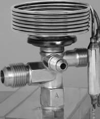

58 EXPANSION VALVES
GENERAL
• Application: Commercial refrigerator, freezer, air conditioner, cold chain box, etc. • Suitable for refrigeration systems with hot gas defrosting. • Type QCX Internal equalizer type Type RCX External equalizer type • The same products can be used for R22 and R407C. • With superheat external adjust device.
• Max. working pressure: 3.0 MPa {30kgf/cm2} • Adjustable range of static superheat: 1 to 7°C at R22, R134a, R404A 1 to 5°C at R407C, R410A • Increase about 0.045MPa / rotation • Superheat change: 4 to 5°C (C, SL–charge) 3 to 4°C (SA–charge)
Catalog No. is decided according to the specifications. Example: Ⅰ: Type...... QCX–Internal equalizer type, RCX–External equalizer type Ⅱ: Model...... The first and the second digits indicate nominal capacity The last two digits indicate inlet and outlet pipe size respectively Ⅲ: Connection....... B–Flare Connection, D–Solder Connection Ⅳ: Refrigerant...... M = R134a, H = R22, R407C, U = R404A, V = R410A Ⅴ: Charge type...... SL = SL–charge, C = C–charge, SA = SA–charge QCX 0234 B U SA Ⅰ Ⅱ Ⅲ Ⅳ Ⅴ Charge A Zone R Zone F Zone MOP (°C) Temp. Condition Evaporating Temp. (°C) Power Element Temp.: TS, Sensing Bulb Temp.: TB SA R22 40 to 10 18 TS ≧ TB C 40 to 0 TS TB SL 60 to 25 20 TS ≧ TB C R134a 30 to 10 TS TB SA R404A 40 to 10 18 TS ≧ TB C 40 to 0 TS TB SL 60 to 25 20 TS ≧ TB SA R407C 40 to 10 18 TS ≧ TB C 40 to 0 TS TB SA R410A 45 to 10 18 TS ≧ TB C 40 to 10 TS TB
Type
QCX–B
Type
RCX–B
Type
QCX–D Type RCX–D Correo: xbombas@gmail.com Telefono: 55 5378 7190
QCX–RCX–
0334B[D]HSL
0534B[D]HSL
QCX–RCX–
QCX–RCX–
QCX–RCX–
Length
0.22 {0.79}
0.33 {1.16}
0834B[D]HSL 0.54 {1.91} 1234B[D]HSL 0.87 {3.07} 1634B[D]HSL 1.10 {3.87} 2434B[D]HSL 1.68 {5.91} 3134B[D]HSL 2.27 {7.97}
R22
4734B[D]HSL 3.10 {10.9}
0234B[D]USL
0.13 {0.46}
0334B[D]USL 0.19 {0.68}
0534B[D]USL 0.32 {1.11}
0834B[D]USL 0.51 {1.79}
R404A
1034B[D]USL 0.64 {2.25}
1534B[D]USL 0.98 {3.44}
2034B[D]USL 1.32 {4.63} 3034B[D]USL 1.80 {6.34}
0334B[D]HC
0.31 {1.10} 0534B[D]HC 0.47 {1.65}
0834B[D]HC 0.78 {2.75} 1234B[D]HC 1.25 {4.41} 1634B[D]HC 1.57 {5.51} 2434B[D]HC 2.35 {8.26} 3134B[D]HC 3.13 {11.0} 4734B[D]HC 4.69 {16.5} 0234B[D]UC
R22
0.20 {0.70} 0334B[D]UC 0.30 {1.05} 0534B[D]UC 0.49 {1.74} 0834B[D]UC 0.78 {2.76} 1034B[D]UC 0.99 {3.48} 1534B[D]UC 1.48 {5.22} 2034B[D]UC 1.98 {6.95} 3034B[D]UC 2.96 {10.4} 0334B[D]HC
R404A
3/8" Flare [B] 3/8" Solder [D]
1/2" Flare [B] 1/2" Solder [D]
2.4 × 1500
0.28 (QCX–**34B) 0.24 (QCX–**34D) 0.29 (RCX–**34B) 0.24 (RCX–**34D)
0.32 {1.13} 0534B[D]HC 0.48 {1.70} 0834B[D]HC 0.81 {2.84} 1234B[D]HC 1.29 {4.54} 1634B[D]HC 1.61 {5.67} 2434B[D]HC 2.42 {8.51} 3134B[D]HC 3.21 {11.3} 4734B[D]HC 4.83 {17.0}
R407C
0234B[D]MC
R134a
0.24 {0.85} 0434B[D]MC 0.36 {1.28} 0634B[D]MC 0.61 {2.13} 1034B[D]MC 0.96 {3.38} 1234B[D]MC 1.21 {4.27} 1834B[D]MC 1.82 {6.40} 2434B[D]MC 2.43 {8.54} 3634B[D]MC 3.64 {12.8}
0334B[D]VC
R410A
0.35 {1.22} 0534B[D]VC 0.52 {1.83} 0934B[D]VC 0.86 {3.04} 1434B[D]VC 1.37 {4.82} 1734B[D]VC 1.73 {6.08} 2634B[D]VC 2.59 {9.12} 3534B[D]VC 3.44 {12.1} 5234B[D]VC 5.18 {18.2}
59 TYPE NUMBER SELECTION (1) ・ External equalizer for RCX: 1/4" flare (for all flare outlet bodies) , 1/4” solder[D] (for all solder outlet bodies) Application Catalog No. Refrigerant Capacity (U.S.R.T.) {kW} Connection Capil. Tube
(mm) Wt. (kg) A,R Zone F Zone C.T 38°C C.T 38°C Inlet Outlet E.T 5°C E.T 30°C
φ
F Zone F r e ez i n g 6 0 t o 2 5° C ( S L : R 2 2 , R 4 0 4 A ) R Zone Re f r ig e r a t io n 4 0 t o 0 ° C ( C : R 2 2 , R 4 0 4 A , R 4 0 7C ) Re f r ig e r a t io n 3 0 t o 1 0 ° C ( C : R 13 4 a ) Re f r ig e r a t io n 4 0 t o 10 ° C ( C : R 41 0 A ) Correo: xbombas@gmail.com Telefono: 55 5378 7190
0534B[D]HSA 0.47 {1.65}
0834B[D]HSA 0.78 {2.75} 1234B[D]HSA 1.25 {4.41}
R22
1634B[D]HSA 1.57 {5.51}
2434B[D]HSA 2.35 {8.26} 3134B[D]HSA 3.13 {11.0}
4734B[D]HSA 4.69 {16.5} 0234B[D]USA
0.20 {0.70} 0334B[D]USA 0.30 {1.05} 0534B[D]USA 0.49 {1.74} 0834B[D]USA 0.78 {2.76} 1034B[D]USA 0.99 {3.48} 1534B[D]USA 1.48 {5.22} 2034B[D]USA 1.98 {6.95} 3034B[D]USA 2.96 {10.4} 0334B[D]HSA
R404A
0.28 (QCX–**34B)
(QCX–**34D)
(RCX–**34B)
(RCX–**34D)
R407C
0.32 {1.13} 0534B[D]HSA 0.48 {1.70} 0834B[D]HSA 0.81 {2.84} 1234B[D]HSA 1.29 {4.54} 1634B[D]HSA 1.61 {5.67} 2434B[D]HSA 2.42 {8.51} 3134B[D]HSA 3.21 {11.3} 4734B[D]HSA 4.83 {17.0} 0334B[D]VSA
0.35 {1.22} 0534B[D]VSA 0.52 {1.83} 0934B[D]VSA 0.86 {3.04} 1434B[D]VSA 1.37 {4.82} 1734B[D]VSA 1.73 {6.08} 2634B[D]VSA 2.59 {9.12} 3534B[D]VSA 3.44 {12.1} 5234B[D]VSA 5.18 {18.2}
R410A
60 TYPE NUMBER SELECTION (2) ・ External equalizer for RCX: 1/4" flare (for all flare outlet bodies) , 1/4” solder (for all solder outlet bodies) DIMENSIONS ACCESSORY ● Sensing Bulb Mounting Band φ2.4×1500 φ2.4×1500 φ2.4×1500 φ2.4×1500 φ39 41 48 48.5 32 L φ39 φφ39 39 10 8 48 48.5 L φφD D φφD D 67 67 67 67 L L 35.5 22.5 22.522.5 41 32 35.5 32 32 22.5 10 8 1/4" Flare [ID] 6.5 Type QCX–B Type QCX–D Type RCX–B Type RCX–D Unit: mm Application Catalog No. Refrigerant Capacity (U.S.R.T.) {kW} Connection Capil. Tube Length (mm) Wt. (kg) A,R Zone F Zone C.T 38°C C.T 38°C Inlet Outlet E.T 5°C E.T 30°C QCX–RCX–0334B[D]HSA
0.31 {1.10} 3/8" Flare [B] 3/8" Solder [D] 1/2" Flare [B] 1/2" Solder [D] φ2.4 × 1500
0.24
0.29
0.24
M5×0.8 bolt 4×9.5(=38) 92 (44) 8.5 23 0.4 φ5×φ5.5 5 5 D L SA 12.7 80 C 9.5 50 SL 12.7 80 A Z o n e A i r C ond it i on i n g 4 0 t o 1 0 ° C ( S A : R 2 2 , R 4 0 4 A , R 4 0 7C ) A r C ond it i on i n g 4 5 t o 1 0 ° C ( S A : R 41 0 A ) Correo: xbombas@gmail.com Telefono: 55 5378 7190
Type
GENERAL DESCRIPTION
SPECIFICATIONS
SA
R134a
SA
R407C
VALVE NOMENCLATURE


61 EXPANSION VALVES
SCX
Type
SCX–D
Type
SCX–B
Catalog No. is decided according to the specifications. Example: Ⅰ: Type...... SCX External equalizer type Ⅱ: Model...... The first and the second digits indicate nominal capacity The last two digits indicate inlet and outlet pipe size respectively Ⅲ: Connection...... B– Flare Connection, D– Solder Connection Ⅳ: Refrigerant...... H = R22, M = R134a, P = R407C, U = R404A, V = R410A Ⅴ: Charge type...... SL = SL– charge, C = C– charge, SA = SA– charge SCX 0445 D U SA Ⅰ Ⅱ Ⅲ Ⅳ Ⅴ
• Application: Chillers, cold chain boxes, heat pump air conditioner, air conditioning, etc. • Suitable for refrigeration systems with hot gas defrosting. • The same products can be used for R22 and R407C. • With superheat external adjust device.
• Max. working pressure: 3.0 MPa {30kgf/cm2} • Adjustable range of static superheat: 1 to 7°C at R22, R134a, R404A 1 to 5°C at R407C, R410A • Increase about 0.045MPa / rotation • Superheat change: 4 to 5°C (C, SL–charge) 3 to 4°C (SA–charge) Charge A Zone R Zone F Zone MOP (°C) Temp. Condition Evaporating Temp. (°C) Power Element Temp.: TS, Sensing Bulb Temp.: TB
R22 40 to 10 18 TS ≧ TB C 40 to 0 TS TB SL 60 to 25 20 TS ≧ TB C
30 to 10 TS TB
R404A 40 to 10 18 TS ≧ TB C 40 to 0 TS TB SL 60 to 25 20 TS ≧ TB SA
40 to 10 18 TS ≧ TB C 40 to 0 TS TB SA R410A 45 to 10 18 TS ≧ TB C 40 to 10 TS TB Correo: xbombas@gmail.com Telefono: 55 5378 7190
63 2 0 159 φ5 5 (10×9.5(=95) 53.4 ) 11×φ5.5 M5×0.8 bolt (φ39) φD 6.5φ L 16.1φ 12.9φ (53) (53) (40)(30) 74 (φ39) φD L (53) (53) (40)(30) 74 10 10 16.1φ 11 φD L (φ39) 6.5φ 22.4φ (53) (53) (40)(30) 74 10 1/4" Flare Type SCX–**45D Type SCX–**57D Type SCX–**45B D L SA 12.7 80 C 9.5 50 SL 12.7 80 DIMENSIONS ACCESSORY ● Sensing Bulb Mounting Band Unit: mm Correo: xbombas@gmail.com Telefono: 55 5378 7190
1–1/8" 1/4"

64 EXPANSION VALVES Type BHX GENERAL DESCRIPTION • Application: General refrigeration and air conditioning system. Note: This valve provides excellent control in unloading, heat pump application, or in a hot gas defrost system. • Charge: S charge for all purpose with 18°C MOP • Max. working pressure: 2.8 MPa {28 kgf/cm2} • Adjustable range of static superheat: 0 to 8°C • Superheat change: 4 to 5°C DIMENSIONS φ15.9 100 φ3×1500 φ61 10 12 62 61 φ15.9 φ61 5451 45 29 100 4330 φ3×1500 122 124 Type BHX–56110B to 56140B Type BHX–71110D to 71140D Unit: mm VALVE NOMENCLATURE Catalog No. is decided according to the specifications. Example: Ⅰ: Type...... BHX–Thermostatic expansion valve for general use Ⅱ: Model...... The first and the second digits indicate inlet and outlet pipe size respectively The last three digits indicate nominal capacity Ⅲ: Connection...... B–Flare Nut Connection, D–Solder Connection Ⅳ: Refrigerant...... M = R134a, H = R 22 Ⅴ: Charge type...... S = S–charge BHX 56110 B H S Ⅰ Ⅱ Ⅲ Ⅳ Ⅴ TYPE NUMBER SELECTION (SPECIFICATIONS) Capacity: Based on condensing temp. 38°C and evaporating temp. 5°C. Catalog No. Capacity (U.S.R.T.) {kW} Connection Capil. Tube Length (mm) Wt. (kg)Type Model Connection Refrigerant Charge R134a R22 Inlet Outlet Equalizer BHX–56110 B (Flare) M (R134a) H (R22) S 13.2 {46.4} 17.6 {61.9} 5/8" 3/4" 1/4" Flare φ3 × 1500 1.04 56140 16.8 {59.1} 22.4 {78.7} 71110 D (Solder) 13.2 {46.4} 17.6 {61.9} 7/8"
Solder 0.85 71140 16.8 {59.1} 22.4 {78.7} Correo: xbombas@gmail.com Telefono: 55 5378 7190
VALVES

Type ATX (R410A)
SPECIFICATIONS
VALVE NOMENCLATURE
65 EXPANSION
GENERAL DESCRIPTION • Applicable for R410A • Application: General refrigeration and air conditioning system. • Suitable for refrigeration systems with hot gas defrosting.
Catalog No. is decided according to the specifications. Example: Ⅰ: Type ... ATX–Thermostatic expansion valve for general use. Ⅱ: Model ... The first and the second digits indicate inlet and outlet pipe size respectively. The last three digits indicate nominal capacity Ⅲ: Connection B–Flare Nut Connection D–Solder Connection Ⅳ: Refrigerant V = R410A Ⅴ: Charge type C = C–charge, CL = CL–charge ATX 34006 B V C Ⅰ Ⅱ Ⅲ Ⅳ Ⅴ
• Max. working pressure: 3.3 MPa {33kgf/cm2} • Adjustable range of static superheat: 1 to 7°C • Increase about 0.007MPa / rotation Charge Evaporating Temp.(℃ ) MOP (℃) Temp. Condition Power Element Temp.: TS, Sensing Bulb Temp.: TB C 10 to 20 TS TB CL 10 to 40 Catalog No. Capacity (U.S.R.T.){kW} Connection Wt. (kg)Type Model Connection Refrigerant Charge CT38℃ ET5℃ Inlet Outlet Equalizer ATX–34006 B (Flare) or D (Solder) V (R410A) C CL 1.10 {3.85} 3/8" 〔3/8"OD〕 1/2" 〔1/2"OD〕 1/4" Flare 1.2 (B) 1.1 〔D〕 34013 2.32 {8.14} 34023 3.98 {14.0} 34035 6.05 {21.3} 34045 7.77 {27.3} 57060 D (Solder) 10.7 {37.6} 5/8"OD or 7/8"ID 7/8"OD or 1-1/8"ID 1.3 57080 14.3 {50.3} 71110 19.6 {69.0} 71140 24.9 {87.4} 71160 28.6 {101} 12220 39.4 {139} 1"OD or 1-1/4"ID 1"OD or 1-1/4"ID 1.5 12270 48.2 {170} 12330 58.6 {206} 12420 74.2 {261} 12500 89.2 {314} TYPE NUMBER SELECTION TYPE ATX–D Correo: xbombas@gmail.com Telefono: 55 5378 7190
ACCESSORY
66 Inlet Outlet AIR SIDE HEAT EXCHANGER HEAT EXCHANGER Type ATX Thermostatic Expansion Valve Type ATX Thermostatic Expansion Valve Check Valve Check Valve RECEIVER ACCUMULATOR COMPRESSOR 4-Way Reversing Valve HEATING CYCLE COOLING CYCLE • In case of using ATX in heat pump circuits, sensing bulb and exter nal equalizer shall be mounted at a position between 4way reversing valve and accumulator SYSTEM EXAMPLE Heat Pump Chiller System 31 30 38 φ68 φ3×2000 φ16 107 100 h A B φ68 φ3×2000 φ16 H 100 OD ID Type H h A B ATX–34006D to 34045D 107 30 31 38 ATX–57060D to 71160D 132 52 34 51 ATX–12220D to 12500D 138 56 36 DIMENSIONS Type ATX B Type ATX D For Type ATX–34006 to 71160 For Type ATX–12220 to 12500
● Sensing Bulb Mounting Band φ6 11×φ6 7 14 16 116.6 10×12.6(=126) 12.6 267 t=0 4 (5.4) φ6 16 174 11×12.6(=138.6) 12.6 337 (5.4) 7 14 t=0 4 12×φ6 Correo: xbombas@gmail.com Telefono: 55 5378 7190
Type ATX
GENERAL DESCRIPTION
EXPANSION VALVES

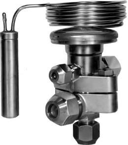
SPECIFICATIONS
VALVE NOMENCLATURE
67
• Application: General refrigeration and air conditioning system. • In cases where the evaporation temperature is 20°C or lower, S–charge type is best suited for heat-pump air conditioners and unloading system attached devices.
• Max. working pressure: 2.8 MPa {28kgf/cm2} (S, SL, CY–charge) 3.3 MPa {33kgf/cm2} (S–charge for R407C) 1.4 MPa {14kgf/cm2} (G, L, C, CL–charge) • Adjustable range of static superheat: 3 to 13°C (G, L, CL–charge) 0 to 13°C (CY–charge) 0 to 8°C (S–charge) 1 to 7°C ........................ (S, SL–charge for R404A) • Increase about 0.007MPa / rotation
Type
ATX–B
Type
ATX–D
Catalog No. is decided according to the specifications. Example: Ⅰ: Type...... ATX–Thermostatic expansion valve for general use. Ⅱ: Model...... The first and second digits indicate inlet and outlet pipe size respectively The last three digits indicate nominal capacity Ⅲ: Connection...... B–Flare Nut Connection, D–Solder Connection Ⅳ: Refrigerant...... M = R134a, H = R22, U = R404A, P = R407C Ⅴ: Charge type...... G = G–charge, L = L–charge, C = C–charge, CL = CL–charge, CY = CY–charge, S = S–charge, SL = SL–charge ATX 34006 B H L Ⅰ Ⅱ Ⅲ Ⅳ Ⅴ Catalog No. Capacity (U.S.R.T.) {kW} Connection Capil.Tube Length (mm) Wt. (kg)Type Model Connection Refrigerant Charge R22 R134a R404A R407C R404A(SL) Inlet Outlet Equalizer ATX–34006 B (Flare) M (R134a) H (R22) U (R404A) P (R407C) S R134a R22 R404A R407A SL (R404A) G L C CL (R22) 1.0 {3.51} 0.7 {2.46} 0.7 {2.46} 1.0 {3.51} 0.3 {1.16} 3/8" 1/2" 1/4" Flare φ3 × 1500 1.2 34013 2.1 {7.39} 1.6 {5.63} 1.5 {5.27} 2.2 {7.74} 0.8 {2.90} 34023 3.6 {12.7} 2.8 {9.85} 2.7 {9.49} 3.7 {13.0} 1.4 {4.78} 34035 5.5 {19.3} 4.2 {14.8} 4.0 {14.1} 5.7 {20.0} 2.0 {7.19} 34045 7.0 {24.8} 5.4 {19.0} 5.1 {17.9} 7.2 {25.3} 2.6 {9.23} ( ) TYPE NUMBER SELECTION Capacity: Based on condensing temp. 38℃ and evaporating temp. 5℃ ( 30℃ for SL–charge). Correo: xbombas@gmail.com Telefono: 55 5378 7190
{7.39} 1.6 {5.63} 1.5 {5.27} 2.2 {7.74} 0.8 {2.90}
34023 3.6 {12.7} 2.8 {9.85} 2.7 {9.49} 3.7 {13.0} 1.4 {4.78}
34035 5.5 {19.3} 4.2 {14.8} 4.0 {14.1} 5.7 {20.0} 2.0 {7.19}
34045
R134a
(R134a)
7.0 {24.8} 5.4 {19.0} 5.1 {17.9} 7.2 {25.3} 2.6 {9.23}
57060 9.7 {34.1} 7.2 {25.4} 6.8 {23.9} 10.0 {35.1} 3.7 {12.9}
57080 13.0 {45.7} 9.6 {33.7} 9.1 {32.0} 13.4 {47.1} 4.9 {17.3}
(R22)
71110 17.8 {62.6} 13.2 {46.4} 12.5 {44.0} 18.3 {64.3} 6.9 {24.4}
(Solder)
5/8" OD or 7/8" ID
7/8" OD or 1–1/8" ID
3 × 2000 1.3
(R404A)
(R404A)
71140 22.6 {79.4} 16.8 {59.1} 16.0 {56.3} 23.3 {81.9} 8.7 {30.7}
71160 26.0 {91.6} 19.2 {67.5} 18.2 {64.0} 26.8 {94.2} 10.0 {35.0}
L C
12220 35.8 {126} 26.4 {92.8} 25.1 {88.3} 36.9 {130} 13.7 {48.2}
(R407C)
(R22)
43.5 {154} 32.4 {114} 30.8 {108} 44.8 {158} 16.9 {59.3}
12330 53.4 {187} 39.6 {140} 37.6 {132} 55.0 {193} 20.6 {72.4} 12420 67.6 {237} 50.4 {177} 47.9 {168} 69.6 {245} 27.6 {97.1} 12500 81.0 {285} 60.0 {211} 57.0 {200} 83.4 {293} 33.0 {116}
Extreme Low Temperature Model ( 70°C to 40°C)
Catalog No. Capacity (U.S.R.T.) {kW} Connection Capil. Tube Length (mm)
Catalog No. Unit: mm Type Model Connection
34006 B (Flare) or D (Solder) 38 107 31 30 64
ATX–
34013 34023 34035 34045 57060 D (Solder) 51
1500 76
132 34 52 2000 57080 71110 71140 71160 12220 138 138 56 68 3000 100 12270 12330 12420 12500
68 DIMENSIONS TYPE NUMBER SELECTION φD φD φ16 φ16 L L H H 1 h φ3 ×ℓ φ3 ×ℓ B HB h H 1 ・ S,CY,SL–Charge : φD=68,ℓ=2000,B=100 Type ATX–D Type ATX–B Unit: mm Capacity: Based on condensing temp. 38℃ and evaporating temp. 5℃.( 30℃ for SL–charge). Catalog No. Capacity (U.S.R.T.) {kW} Connection Capil TubeLength (mm) Wt. (kg)Type Model Connection Refrigerant Charge R22 R134a R404A R407C R404A(SL) Inlet Outlet Equalizer ATX–34006 D
M
H
U
P
S
R22 R404A R407C SL
G
CL
1.0 {3.51} 0.7 {2.46} 0.7 {2.46} 1.0 {3.51} 0.3 {1.16} 3/8" OD 1/2" OD 1/4" Flare φ3 × 1500 1.1 34013 2.1
φ
1" OD or 1–1/4" ID 1" OD or 1–1/4" ID φ3 × 3000 1.5 12270
L H H1 h φD ℓ B
Capacity: Based on condensing temp. 40℃ and evaporating temp. 60℃, sub-cooling 50℃
Wt. (kg)Type Model Connection Refrigerant Charge R22 Inlet Outlet Equalizer ATX–34006 B (Flare) or D (Solder) H (R22) CY Extreme Low 1.39 {4.88} 3/8"OD 1/2"OD 1/4" Flare φ3 × 2000 1.2 (Flare) 1.1 (Solder) 34013 3.21 {11.3} 34023 5.40 {19.0} 34035 7.56 {26.6} 34045 9.74 {34.3} 57060 D (Solder) 11.3 {39.8} 5/8"OD or 7/8"ID 7/8"OD or 1-1/8"ID 1.3 57080 15.3 {53.7} For Type ATX–34006 to 71160 For Type ATX–12220 to 12500 ACCESSORY ● Sensing Bulb Mounting Band φ6 11×φ6 7 14 16 116.6 10×12.6(=126) 12.6 267 t=0 4 (5.4) φ6 16 174 11×12.6(=138.6) 12.6 337 (5.4) 7 14 t=0 4 12×φ6 ( ) Correo: xbombas@gmail.com Telefono: 55 5378 7190
GENERAL DESCRIPTION
VALVE NOMENCLATURE


69 EXPANSION VALVES High Volume OEM Item Type AEX
• T hi s p ro d u ct d e mo n st r a t es e x ce l l e nt p e rf o r ma n c e o ve r a wide range of evaporation temperature. • The AEX-Z type adopts a bellows seal mechanism and performs stable control even at extremely low temperatures. • Application: Refrigerator, Freezer, Extreme low temperature warehouse and Refrigeration equipment for Ships.
Catalog No. is decided according to the specifications. Example: Ⅰ: Type...... AEX–Thermostatic expansion valve for general use. (Internal equalizer type.) Ⅱ: Model...... The first and the second digits indicate inlet and outlet pipe size respectively The last two digits indicate nominal capacity Ⅲ: Connection...... B–Flare Nut Connection Ⅳ: Refrigerant...... H = R22, M=R134a, C=R23, U=R404A Ⅴ: Temperature class...... no representation = standard type, Z = Extreme Low Temperature type AEX 2333 B H Z Ⅰ Ⅱ Ⅲ Ⅳ Ⅴ TYPE NUMBER SELECTION (SPECIFICATIONS) ・ Capacity: Based on condensing temp. 38°C and evaporating temp. 5°C. ・ If you need connection sizes in ( ), please specify first. ・ H dimension of Z type is about 24 mm larger SPECIFICATIONS • Max. working pressure: 1.4MPa {14 kgf/cm2} • Airtight test pressure: 1.6MPa{16 kgf/cm2} • Body and sensing bulb Max. temperature: 80°C • Adjustable range of static superheat: 0 〜 20°C Increase about 0.05 MPa / rotation Type AEX Type AEX–Z Charge Temperature class Refrigerant Evaporating Temp. (°C) MOP (°C) Temp. Condition Power Element Temp.: TS Sensing Bulb Temp.: TB G R22 standard H 10~−40 13 TS﹥TB R134a M 10~ 30 R404A U 10~ 40 R22 Extreme Low Temperature H 10~ 70 R23 C(R23) 70~ 100 60 R404A U 10~ 70 13 Catalog No. Capacity (U.S.R.T.) {kW} Connection Wt. (kg)Type Model Connection Refrigerant R22 R23 R134a R404A Inlet Outlet AEX2333B H (R22) M (R134a) C (R23) U (R404A) No representation (standard) Z (Extreme Low Temperature) 0 50 {1 76} Production possible 0 36 {1 27} 0 34 {1 20} 1/4"(3/8") Flare 3/8" Flare 0.95 2335B 0 95 {3 34} 0 72 {2.53} 0 68 {2.39} 1.15 2345B 1/2" Flare 2348B 1.40 {4.92} 1.10 {3 87} 1 05 {3 69} 2341B 1 90 {6 68} 1 50 {5 28} 1.40 {4.92} 2342B 3.70 {13.0} 2 60 {9.14} 2 50 {8.79} 3/8"(1/4") Flare2344B 6 0 {21.1} 4.41 {15 5} 4.21 {14.8} 1 30 3454B 1/2" Flare 5/8" Flare 1.55 4564B 5/8"(1/2") Flare 3/4" Flare4566B 9.61 {33 8} 7.20 {25 3} 6 0 {21.1} 4568B 12 8 {45 0} 9.58 {33 7} 8 39 {29.5} G:Gas charge Type Correo: xbombas@gmail.com Telefono: 55 5378 7190
70 DIMENSIONS Unit: mm Type AEX Type AEX–Z Catalog No L H h Type Model Refrigerant Evaporating Temp AEX2333B H (R22) M (R134a) C (R23) U (R404A) No representation (standard) Z (Extreme Low Temperature) 70.5 132 47 (46) 2335B 2345B 73.5 2348B 2341B 2342B 46(47) 2344B 81 133 48(49) 3454B 84.5 135 52 4564B 90.5 136 56.5 (55.5)4566B 4568B φ9.5 Adjusting bolt Adjusting bolt H h L 80 φ2.4×1300 φ9.5 H h L 80 φ3×1300 Correo: xbombas@gmail.com Telefono: 55 5378 7190
ELECTRONIC EXPANSION VALVES


Volume
Type UKV, VKV & AKV
GENERAL DESCRIPTION
SPECIFICATIONS
TYPE NUMBER SELECTION
UKV–08D
UKV–10D 1.0 0.7 {2.6} 0.58 {2.0} 0.5 {1.8} 0.8 {2.7} 0.9 {3.1}
UKV–14D 1.4 1.6 {5.8} 1.28 {4.5} 1.2 {4.1} 1.7 {5.9} 1.9 {6.8}
UKV–18D 1.8 2.9 {10.3} 2.3 {8.1} 2.1 {7.3} 3.0 {10.6} 3.4 {12.1}
UKV–25D 2.5 5.6 {19.6} 4.4 {15.3} 3.9 {13.8} 5.7 {20.1} 6.5 {23.0}
UKV–30D 3.0 7.6 {26.8} 6.0 {20.9} 5.4 {18.9} 7.8 {27.5} 9.0 {31.5}
7.94
7.94
6.35
7.94
Item
6.35
7.94
{20}
less
3.5 {35} or less
2.0 {20} or less
2.8 {28} or less
2.2 {22} or less
to 2.8 {0 to 28} 1.5 {15} or less
UKV–32D 3.2 8.2 {28.8} 6.4 {22.5} 5.8 {20.3} 8.4 {29.6} 9.6 {33.9} 1.2 {12} or less
UKV–40D 4.0 11.1 {39.1} 8.7 {30.6} 7.9 {27.6} 11.4 {40.2} 13.1 {46.0}
to 2.1 {0 to 21} 0.7 {7} or less
VKV–14D
VKV–18D
2.9 {10.3} 2.3 {8.1}
VKV–20D 2.0 3.5 {12.4} 2.7 {9.7}
VKV–25D 2.5 5.3 {18.5} 4.1
VKV–30D
VKV–32D
{28.8}
{8.7}
less
{24} or less
{24} or less 0.13
71 High Volume OEM Item
High
OEM
• Application: Wide range of air conditioning and refrigeration equipment • Refrigerant: R22, R134a, R404A, R407C, R410A • High cool down capability • Quick response. • Less energy consumption. • Bi-Flow capability.
Max. working pressure: 4.2 MPa {42kgf/cm2} Valve operating pulse range: 0 to 480 pulse, 1–2 phase excitation. Type UKV Type AKV
Type UKV High volume OEM item ・ Capacity: Based on CT = 38°C, ET = 5°C, SC = 0°C and SH = 0°C ・ Please contact us if other capacity or connection are required. Catalog No. Port Size (φmm) Capacity (U.S.R.T.) {kW} Connection (Solder) (mm) Operating Pressure Differential B to A flow direction (MPa) {kgf/cm2} Valve shut press on, A to B flow direction (MPa) {kgf/cm2} Wt. (kg) R22 R134a R404A R407C R410A B side A side
0.8 0.4 {1.5} 0.34 {1.2} 0.3 {1.1} 0.4 {1.6} 0.5 {1.8} φ6.35 OD φ6.35 OD 0 to 3.5 {0 to 35} 2.0
or
0.05
φ
OD φ7.94 OD
φ
OD φ7.94 OD
φ
OD φ
OD
φ
OD φ
OD
0
0
Type VKV Middle volume OEM item ・ Capacity: Based on CT = 38°C, ET = 5°C, SC = 0°C and SH = 0°C ・ Please contact us if valves for application of hot gas bypass are required. Catalog No. Port Size (φmm) Capacity (U.S.R.T.) {kW} Connection (Solder) (mm) Operating Pressure Differential B to A flow direction (MPa) {kgf/cm2} Valve shut press on, A to B flow direction (MPa) {kgf/cm2} Wt. (kg) R22 R134a R404A R407C R410A B side A side
1.4 1.5 {5.2} 1.1 {4.0} 1.0 {3.6} 1.5 {5.3} 1.7 {6.1} φ7.94 OD φ7.94 OD 0 to 3.5 {0 to 35} 2.8 {28} or
0.11
1.8
2.1 {7.3} 3.0 {10.6} 3.4 {12.1} 2.4
2.5
3.6 {12.7} 4.1 {14.5} 2.4
{14.5} 3.7 {13.1} 5.4 {19.0} 6.2 {21.8} 2.2 {22} or less
3.0 7.0 {24.7} 5.5 {19.3} 4.9 {17.4} 7.2 {25.4} 8.3 {29.1} 0 to 2.5 {0 to 25} 1.5 {15} or less
3.2 8.2
6.4 {22.5} 5.8 {20.3} 8.4 {29.6} 9.6 {33.9} φ9.52 OD φ12.7 OD 1.0 {10} or less 0.15 VKV–40D 4.0 13.2 {46.4} 10.3 {36.2} 9.3 {32.7} 13.5 {47.6} 15.5 {54.5} φ12.7 OD φ12.7 OD 0.3 {3} or less 0.16 Correo: xbombas@gmail.com Telefono: 55 5378 7190
Type
UKV–10D
UKV–14D UKV–18D
UKV–25D
UKV–30D UKV–32D UKV–40D
VKV–14D
VKV–18D VKV–20D VKV–25D VKV–30D
72 (37) (φ48) A side Conn. E D (A) ( B ) ( C ) B side Conn. DIMENSIONS Type UKV B Side Conn. 47 A B A Side Conn. (47) (43) (32) (99) 50 Type VKV 14D to 32D Catalog No. A B UKV–08D φ6.35
φ7.94
φ6.35
φ7.94
Catalog No. A B C D E
64 49 112 φ7.94
VKV–32D 66 64 130 φ9.52 φ12.7 Coil Valve Type Rated Voltage & Current Wt.(kg)
UKV 12V DC…260mA/Phase 0.13 Type VKV 12V DC…380mA/Phase 0.15 Type AKV 12V DC…375mA/Phase 0.4 Type AKV Large capacity type ・ Capacity: Based on CT = 38°C, ET = 5°C, SC = 0°C and SH = 0°C Catalog No. Port Size (φmm) Capacity (U.S.R.T.) {kW} Connection (Solder) (mm) Operating Pressure Differential B to A flow direction (MPa) {kgf/cm2} Valve shut press on, A to B flow direction (MPa) {kgf/cm2} Wt. (kg) R22 R134a R404A R407C R410A B side A side AKV–55D 5.5 23.7 {83.4} 18.5 {65.2} 16.7 {58.8} 24.4 {85.6} 27.9 {98.1} φ15.88 OD φ15.88 OD 0 to 2.3 {0 to 23} 0.5 {5} or less 0.4 AKV–65D 6.5 28.1 {98.9} 22.0 {77.3} 19.8 {69.8} 29.9 {105.2} 33.0 {116.2} 0.42 Unit: mm Correo: xbombas@gmail.com Telefono: 55 5378 7190
73 DIMENSIONS Type AKV D A side Conn. (φ67) (B) (A) (C) B side Conn. E Catalog No. A B C D E AKV–55D 64.5 65.5 150 φ15.88 AKV–65D Unit: mm A side Conn. B side Conn. φ48 D E (C) (B) (A) Type VKV 40D Catalog No. A B C D E VKV 40D 66 68 136 φ12.7 φ12.7 Correo: xbombas@gmail.com Telefono: 55 5378 7190
SPECIFICATIONS

74 APPLICATION EXAMPLE Electronic expansion valve UKV‒F COMPRESSOR ACCUMULATOR HEATING CYCLE COOLING CYCLE OUTDOOR UNIT Expansion Valve Check Valve INDOOR UNIT E Electronic expansion valve UKV‒F Expansion Valve Check Valve EEV1E EEV2 HEAT EXCHANGER HEAT EXCHANGER Unit: mm ELECTRONIC EXPANSION VALVES High Volume OEM Item Type UKV–F GENERAL DESCRIPTION • Application: Residential air conditioner, etc. • Refrigerant: R22, R134a, R404A, R407C, R410A • With inter nal check valve function. • High cool down capability • Quick response. • Less energy consumption.
Max. working pressure: 4.2 MPa {42kgf/cm2} Valve operating pulse range: 0 to 500 pulse, 1–2 phase excitation. Type UKV–F ・ Capacity: Based on CT = 38°C, ET = 5°C, SC = 0°C and SH = 0°C Catalog No. Port Size (φmm) Capacity (U.S.R.T.) {kW} Connection (Solder) (mm) Operating Pressure Differential (MPa) {kgf/cm2} Cv Value Flow Direction A to B Full opening position Wt. (kg)Flow Direction R22 R134a R404A R407C R410A B side A side B to A A to B UKV–F19D 1.9 2.9 {10.3} 2.3 {8.1} 2.1 {7.3} 3.0 {10.6} 3.4 {12.1} φ7.94 OD φ7.94 OD 0 to 3.3 {0 to 33} N/A 0.47 0.05 UKV–F25D 2.5 4.7 {16.5} 3.7 {12.9} 3.3 {11.6} 4.8 {16.9} 5.5 {19.4} TYPE NUMBER SELECTION Type UKV–F With internal check valve function Coil Rated Voltage & Current Wt.(kg) 12V DC…260mA/Phase 0.13 DIMENSIONS B Side Conn. 47 A B A Side Conn. (47) (43) (32) (99) 50 A B Catalog No. A B UKV–F19D φ7.94 UKV–F25D B → A: Flow when the valve works as an expansion valve. A→ B: Flow when the valve works as a tube. COOLING CYCLE EEV1: Flow when the valve works as a tube. EEV2: Flow when the valve works as an expansion valve. HEATING CYCLE EEV1: Flow when the valve works as an expansion valve EEV2: Flow when the valve works as a tube. High Volume OEM Item Correo: xbombas@gmail.com Telefono: 55 5378 7190
Type LNE

WIRING
DIMENSIONS
75 PULSE CONVERTERS
GENERAL DESCRIPTION • Can be used for all types of VKV, PKV, and AKV electronic expansion valves. • Current input is converted to driving pulse output to electronic expansion valve with the pulse converter. • Convert 4 to 20mA. DC input to 0 to 480 pulse output. 1 U Power Supply 24V AC or 24V DC KV series Ele. Exp. Valve Start up Signal 4 to 20mA. DC Current Input V C COM ST SIG + ASIG B A B 2 3 4 5 6 7 8 9 10 11 12 13 14 15 16 17 18
RUN PULSE CONVERTER 106 58 90 U V C A B A B COM ST POWER: AC/DC 24V INPUT DC 4 20mA VALVE: 12V COIL ONLY
(Type: LNE–ZN20–020) Unit: mm (Wt. 0.25kg) Input Start up input No voltage contact signal Current input 4 to 20mA. DC Output 0 to 480 pulse For VKV, PKV & AKV Sampling time 0.1, 1, 5, and 10 sec. Correo: xbombas@gmail.com Telefono: 55 5378 7190
SOLENOID VALVES & CONTROL VALVES
SOLENOID VALVES FOR REFRIGERANT 77 Type TEV & VPV
SOLENOID VALVES FOR REFRIGERANT 78–79 Type SEV
SOLENOID VALVES FOR REFRIGERANT
80–81 Type RPV
SOLENOID VALVES FOR REFRIGERANT 82–84 Type REV & UEV
SOLENOID VALVES FOR WATER 85 Type WEV
SOLENOID VALVES
Type BPV 3-WAY SOLENOID VALVES 87 Type IEV 4-WAY REVERSING VALVES 88–90 Type STF
MOTORIZED BALL VALVES 91–92 Type MJV
DAMPER & VALVE MOTOR ACTUATORS 93–94 Type EGK & WGK 2-WAY & 3-WAY CONTROL VALVES
95–97 Type NVK
・・・・・・・・
BI-FLOW
・・・・・・・・・・・・・・・・・・・ 86
・・・・・・・・・・・・
SOLENOID V AL VES & CONTROL V AL VES
Correo: xbombas@gmail.com Telefono: 55 5378 7190
TYPE NUMBER SELECTION
TEV–S1220D
0.037
TEV–S1620D 1.6 0.07 0.3 {1.0} 0.3 {1.0} 0.2 {0.7} 0.3 {1.1}
TEV–S1920D 1.9 0.1 0.4 {1.5} 0.4 {1.5} 0.3 {1.0} 0.5 {1.6} 2.75 {28}
3.6 {36.7} 4.3 {43.8}
Normal Close 0.025
VPV–L202D 1.8 0.06 0.3 {1.0} 0.3 {1.0} 0.2 {0.7} 0.3 {1.1} 1/4" 0 2.06 {21} Normal Open 0.06
VPV–603D 5.8 0.65 2.8 {9.7} 2.7 {9.6} 1.9 {6.7} 2.9 {10.3} 5/16" 0.005 {0.05} 3.6 {36.7}

Normal Close 0.08
VPV–803DQ50 7.8 1.5 6.4 {22.4} 6.3 {22.2} 4.4 {15.4} 6.8 {23.8} 3/8" 0.01 {0.1} 2.75 {28} 0.14
VPV–1204DQ50 11.0 3.0 12.7 {44.8} 12.6 {44.4} 8.8 {30.9} 13.5 {47.6} 1/2" 0.015 {0.15} 0.26

77 SOLENOID VALVES FOR REFRIGERANT High Volume OEM Item Type TEV & VPV GENERAL DESCRIPTION • Direct-operated, pilot operated, 2-way, normally closed valve. Normally open type is available. • For use with non-corrosive refrigerant. • C o m p a c t l y d e s i g n e d f o r u s e i n s m a l l a p p l i a n c e s p ro duced in quantity such as room air conditioners, dehu midifiers and ice making machines. • Various piping configuration available. Type VPV Type TEV DIMENSIONS (H) h L (47) 18.512.5 l Inlet Inlet 35 35 (H) h L (H) h L figure 1 figure 3 figure 2 Unit: mm High Volume OEM Item SPECIFICATIONS • Fluid temperature: 30 to 120°C • Ambient temperature: 30 to 50°C
O.P.D.: Operating Pressure Differential (by air pressure) * Nominal capacities are based on ΔP = 0.015MPa, condensing temp. = 38°C and evaporating temp. = 5°C Unit: MPa {kgf/cm2} Catalog No. Port Size (mm) Cv Value Nominal Capacity (U.S.R.T.) {kW} Connection O.P.D. Max. Working Pressure Operation Wt. (kg)R410A R134a R404A R22 Copper Tube O.D. Style Min. Max.
1.2
0.2 {0.6} 0.1 {0.5} 0.1 {0.4} 0.2 {0.6} 1/4" Solder 0
Catalog No. Unit: mm Form L H h I TEV–S1220D 35 40 33 figure 1S1620D S1920D VPV–603D 36.5 55 36 figure 2 803DQ50 41.5 53.5 38.5 22.5 figure 3 1204DQ50 61.5 57.5 61.5 28.5 L202D figure 4 Current (A) = Voltampere / Rated Voltage * IEC compliance ELECTRICAL RATING OF SOLENOID COILS Type Rated Voltage Tolerance (%) Voltampere Power Consumption (W) Insulation Class Wt. Running(kg) Inrush TEV 24V. AC 100V. AC 110V. AC 120V. AC 208V. AC 220V. AC 230V. AC 240V. AC 50/60Hz ±10 9/7 22/16 4.5/3.5 Class B Molded 0.1 VPV 13/10 36/30 8/7 0.14 * figure 4 * Correo: xbombas@gmail.com Telefono: 55 5378 7190
Type SEV
GENERAL DESCRIPTION
TYPE NUMBER SELECTION
SEV–303BXF
SEV–502BXF
SEV–502BYF
SEV–603BXF
SEV–603BYF
SEV–1004BXF
SEV–1004BYF
SEV–1205BXF
SEV–1205BYF
SEV–1506BXF
SEV–1506BYF
SEV–502DXF
SEV–502DYF

SEV–603DXF
SEV–603DYF
SEV–1004DXF
SEV–1004DYF
SEV–1205DXF
SEV–1205DYF
SEV–1506DXF
SEV–1506DYF

0.51 3.5 {12.4} 2.2 {7.6}
FOR REFRIGERANT
{5.2}
{8.1}
0.80 8.5 {29.8} 3.4 {11.8} 2.3 {8.2} 3.6 {12.7} 3/8"
1.75 14.8 {52.2} 7.4 {25.9} 5.1 {18.0} 7.9 {27.8} 1/2"
2.45
0.7
12 2.9 22.5 {79.1} 12.2 {42.9} 8.5 {29.8} 13.1 {46.0} 5/8" 1.0
0.007 {0.07}
2.94
4.41
5 0.53 2.2 {7.9} 2.2 {7.9} 1.5 {5.5} 2.4 {8.4} 1/4"
1.96 {20}
4.2
40 to 125
30 to 50
15 4.5 19.1 {67.2} 18.9 {66.6} 13.2 {46.3} 20.3 {71.4} 3/4" 1.4
0 0.3
6 0.83 3.5 {12.4} 3.5 {12.3} 2.4 {8.5} 3.8 {13.2} 3/8" 0.35
10 2.0 8.5 {29.8} 8.4 {29.6} 5.9 {20.6} 9.0 {31.7} 1/2"
Solder
0.7
12 3.5 14.8 {52.2} 14.7 {51.8} 10.2 {36.0} 15.8 {55.5} 5/8" 0.8
0.007 {0.07}
5.3 22.5 {79.1} 22.3 {78.5} 15.5 {54.5} 23.9 {84.1} 3/4" 1.0
78 SOLENOID VALVES
• Pilot operated, 2-way, normally closed valve. • F o r n o n c o r r o s i v e r e f r i g e r a n t ( l i q u i d o r g a s ) i n refrigeration units. Also available for air application. • Can operate under no pressure difference. (SEV–303, 502 and 603) • Can install horizontally and vertically (Coil should be located above the axis of pipe line.)
Unit: MPa {kgf/cm2} Catalog No. Port Size (mm) Cv Value Nominal Capacity (U.S.R.T.) {kw} Connection O.P.D. Max. Working Pressure Body Test Press. Fluid Temp. (°C) Ambient Temp. (°C) Wt. (kg) R410A R134a R404A R22 Copper Tube O.D. Style Min. Max.
3 0.25 2.25 {7.91} 1.05 {3.7} 0.73 {2.57} 1.13 {3.97} 3/8” Flare 0
{25} for AC
for DC X:
{30} Y:
{42} X:
{45} Y: 6.3 {63}
0.4
5
1.5
2.3
1/4"
6
10
15
Current (A) = Voltampere / Rated Voltage ELECTRICAL RATING OF SOLENOID COILS * IEC compliance Rated Voltage Tolerance (%) Voltampere (VA) Power Consumption (W) Insulation Class Running Inrush 24V.AC, 100V.AC, 110V.AC 200V.AC, 220V.AC, 240V.AC 50/60Hz ±10 15/11 45/33 7/6 Class B Molded 12V DC, 24V DC, 100V DC 10 * Type SEV–B Type SEV–D * * Nominal capacities are based on ΔP = 0.015 MPa, condensing temp. = 38°C and evaporating temp. = 5°C, Supercool temp. = 0°C ・Weight includes a coil ・Enclosure IP34 (SEV-W:Drip proof model) Correo: xbombas@gmail.com Telefono: 55 5378 7190
58 11.5
105 85 20.5
115 88 22
135 95 25
58 10.5
160 85 20.5
180 88 22
190 95 25
79 DIMENSIONS L 18 Strainer 39 h H 39 L H h Type SEV–B Type SEV–D Unit: mm Catalog No. Unit: mm L H h SEV–303B 85
502B 603B 1004B
1205B
1506B
502D 270
603D 1004D
1205D
1506D
Correo: xbombas@gmail.com Telefono: 55 5378 7190
SOLENOID VALVES FOR REFRIGERANT


Type RPV
GENERAL DESCRIPTION
SPECIFICATIONS
TYPE NUMBER SELECTION
RPV–302BYF
{4.3}
0.3
RPV–303BYF 0.30 1.3 {4.5} 1.3 {4.4} 0.9 {3.1} 1.4 {4.8} 3/8" 0.3
RPV–602BYF
RPV–803BYF
0.60 2.5 {9.0} 2.5 {8.9} 1.8 {6.2} 2.7 {9.5} 1/4" 0.4
RPV–603BYF 0.90 3.8 {13.4} 3.8 {13.3} 2.6 {9.3} 4.0 {14.0} 3/8" 0.4
0.45
RPV–804BYF 1.4 5.9 {20.9} 5.9 {20.7} 4.1 {14.4} 6.3 {22.0} 1/2" 0.45
RPV–1004BYF 10 2.4 10.2 {35.8} 10.1 {35.5} 7.0 {24.7} 10.8 {38.0} 1/2" 0.6
1.2 5.1 {17.9} 5.1 {17.8} 3.5 {12.3} 5.4 {19.0} 3/8" 0.005 {0.05}
RPV–1005BYF 2.4 10.2 {35.8} 10.1 {35.5} 7.0 {24.7} 10.8 {38.0} 5/8" 0.6
RPV–1205BYF 12 3.6 15.3 {53.7} 15.2 {53.3} 10.5 {37.0} 16.2 {57.0} 5/8" 0.7
RPV–1606BYF 16 5.6 23.8 {83.6} 23.6 {82.9} 16.4 {57.6} 25.3 {89.0} 3/4" 1.1
RPV–302DYF 3 0.27 1.1 {4.0} 1.1 {4.0} 0.8 {2.8} 1.2 {4.3} 1/4"
0 3.6 {36.7} 4.3 {43.8}
0.3
RPV–303DYF 0.30 1.3 {4.5} 1.3 {4.4} 0.9 {3.1} 1.4 {4.8} 3/8" 0.3
0
RPV–602DYF 6 0.60 2.5 {9.0} 2.5 {8.9} 1.8 {6.2} 2.7 {9.5} 1/4" 0.4
RPV–603DYF 0.90 3.8 {13.4} 3.8 {13.3} 2.6 {9.3} 4.0 {14.0} 3/8" 0.4
0.4
RPV–804DYF 1.4 5.9 {20.9} 5.9 {20.7} 4.1 {14.4} 6.3 {22.0} 1/2" 0.4
Solder
RPV–1004DYF 10 2.4 10.2 {35.8} 10.1 {35.5} 7.0 {24.7} 10.8 {38.0} 1/2" 0.6
RPV–1005DYF 2.4 10.2 {35.8} 10.1 {35.5} 7.0 {24.7} 10.8 {38.0} 5/8" 0.6
RPV–803DYF 8 1.2 5.1 {17.9} 5.1 {17.8} 3.5 {12.3} 5.4 {19.0} 3/8" 0.005 {0.05}
RPV–1205DYF 12 3.6 15.3 {53.7} 15.2 {53.3} 10.5 {37.0} 16.2 {57.0} 5/8" 0.7
RPV–1606DYF 16 5.6 23.8 {83.6} 23.6 {82.9} 16.4 {57.6} 25.3 {89.0} 3/4" 1.1
RPV–1607DYF 5.6 23.8 {83.6} 23.6 {82.9} 16.4 {57.6} 25.3 {89.0} 7/8" 1.1
80
• New solenoid valves for r efrigerant "High-pr essur e R410A standard" • Various product line up (Body: 21 types, Coil: DIN plug type, Lead wire type) • Low power consumption (6W at 50Hz / 4.5W at 60Hz) Type RPV–D Type RPV–B
• Body test pressure: 6.5MPa (66.2kgf/cm2) • Fluid temperature: 40 to 125°C • Ambient temperature: 30 to 50°C
Enclosure Lead wire direct: IP67 / DIN: IP65 (When DIN socket is used) Nominal capacities (R410A) are based on ⊿P = 0.015 MPa, condensing temp. = 38°C and evaporating temp. = 5°C ・ Weight includes a coil (Without Strainer, Flare nuts, Bracket). Unit: MPa {kgf/cm2} Catalog No. Port Size (mm) Cv Value Nominal Capacity (U.S.R.T.) {kW} Connection O.P.D. Max. Working Pressure Wt. (kg) R410A R134a R404A R22 Copper Tube O.D. Style Min. Max.
3 0.27 1.1 {4.0} 1.1 {4.0} 0.8 {2.8} 1.2
1/4" Flare
6
8
For *3 to *6, please refer to the following ELECTRICAL RATING OF SOLENOID COILS *1 EN 175301-803 (DIN 43650) / ISO 4400 *2 Enclosure Lead wire direct: IP67 / DIN: IP65 (When DIN socket is used) Rated Voltage Tolerance (%) Voltampere (VA) Power Consumption (W) Insulation Class Coil Style Running Inrush Lead wire DIN plug 24V.AC 50/60Hz ±10 12.5/9.5 45/44 6/4.5 Class B Molded ○ ○ 100V.AC 200V.AC 220V.AC 230V.AC 240V.AC *3 *4 *5 *6 In case of the following voltage and frequency Voltampere (VA) Power Consumption Running(W) *3 200 to 208V AC(60Hz) 9.5 to 11 4.5 to 5 *4 220 to 230V AC(60Hz) *5 220 to 230V AC(50Hz) 10.5 to 12.5 5.2 to 6 *5 230 to 240V AC(60Hz) 9.5 to 11 4.5 to 5 *6 230 to 240V AC(50Hz) 10.5 to 12.5 5.2 to 6 *1 *2 Correo: xbombas@gmail.com Telefono: 55 5378 7190
Type RPV–302BYF, 303BYF
Type RPV–1004BYF to 1606BYF
Type RPV–602BYF to 804BYF
Catalog No.
RPV–302BYF
RPV–303BYF
RPV–602BYF
RPV–603BYF
RPV–803BYF
RPV–804BYF
RPV–1004BYF
RPV–1005BYF
RPV–1205BYF
RPV–1606BYF
Type RPV–302DYF, 303DYF
Type RPV–1004DYF to 1607DYF
mm
12.5
12.5
15 12
15 12
15 14
15 14
15.5 17
15.5 17
17 20
19 24
Type RPV–602DYF to 804DYF
Mounting Hole for Ground
Catalog No. Unit: mm
RPV–302DYF
RPV–303DYF
H h d
67 12.5 12
67 12.5 12
RPV–602DYF 140 74 15 12
RPV–603DYF 138 74 15 12
RPV–803DYF 141 75.5 15 14
RPV–804DYF 139 75.5 15 14
RPV–1004DYF 158 77 15.5 17
RPV–1005DYF 168 77 15.5 17
RPV–1205DYF 171 82 17 20
RPV–1606DYF 196 89 19 24
RPV–1607DYF 196 89 19 24
OPTIONAL PARTS
81 12 1043 5 L H h 5 1043 H h L 12 M5×0.8 Depth d 48 5 H h L M5×0.8 Depth d M5×0.8 Depth d M5×0.8 Depth d Thread Mounting Hole for Ground M4×0.7 Depth 2 Thread Mounting Hole for Ground M4×0.7 Depth 2 12 1043 5 H h L M5×0.8 Depth d Flow Direction Flow Direction 48 H h L 5 48 5 H h L M5×0.8 Depth Flowd Direction Flow Direction Thread
M4×0.7 Depth 2 DIMENSIONS Unit: mm
Unit:
L H h d
64 67
12
68 67
12
71 74
78 74
84 75.5
90 75.5
96 77
101 77
104 82
124 89
L
123
123
DIN socket for DIN plug coil Flare Nut 33 12 Gasket Fixing screw (□30) 30.5 Connector 42 PG 9 Correo: xbombas@gmail.com Telefono: 55 5378 7190
SOLENOID VALVES FOR REFRIGERANT


Type REV & UEV
GENERAL DESCRIPTION
REV
operated,
non-corrosive
SPECIFICATIONS
Type
Type
TYPE NUMBER SELECTION
REV–703BXF
REV–1004BXF
1.0 4.2 {14.9} 4.2 {14.8}
{10.3} 4.6
2.0 8.5 {29.8} 8.4 {29.6} 5.9 {20.6} 9.1 {32} 1/2" 0.9
REV–1205BXF 12 3.5 14.9 {52.2} 14.7 {51.8} 10.2 {36} 15.9 {56} 5/8" 1.1
REV–1506BXF 15 5.3 22.5 {79.1} 22.3 {78.5} 15.5 {54.5} 23.9 {84} 3/4" 1.5
REV–1003GXF 10 2.0 8.5 {29.8} 8.4 {29.6} 5.9 {20.6} 9.1 {32} 3/8" Rc 1.0
REV–1204GXF 12 3.5 14.9 {52.2} 14.7 {51.8} 10.2 {36} 15.9 {56} 1/2" 1.3
REV–1506GXF 15 5.3 22.5 {79.1} 22.3 {78.5} 15.5 {54.5} 23.9 {84} 3/4" 1.7
REV–703DXF 7 1.0 4.2 {14.9} 4.2 {14.8} 2.9 {10.3} 4.6 {16} 3/8"
0.5
REV–1004DXF 10 2.0 8.5 {29.8} 8.4 {29.6} 5.9 {20.6} 9.1 {32} 1/2" 0.8
REV–1205DXF 12 3.5 14.9 {52.2} 14.7 {51.8} 10.2 {36} 15.9 {56} 5/8" 0.9
REV–1506DXF 15 5.3 22.5 {79.1} 22.3 {78.5} 15.5 {54.5} 23.9 {84} 3/4" 1.1
REV–2007DXF
REV–2010DXF 1"
REV–2011DXF
REV–2511DXF
20 9.0 38.2 {134.3} 37.9 {133.2} 26.3 {92.6} 40.7 {143} 7/8" 1.6
1–1/8"
REV–2512DXF 1–1/4"
Solder
{25}
{30}
13.8 58.1 {204.3} 40.4 {141.9} 62.3 {219} 1–1/8" 2.2
REV–2513DXF 1–3/8"
REV–3213DXF
REV–3214DXF 1–1/2"
REV–3215DXF
REV–2006EXF
REV–2510EXF
REV–3212EXF
REV–4014EXF
REV–5020EXF
19.4 81.7 {287.2} 56.7 {199.5} 87.6 {308}
9.0 38.2 {134.3} 37.9 {133.2} 26.3 {92.6} 40.7 {143} 7/8" 1–1/8" 3/4"
13.8 58.1 {204.3} 40.4 {141.9}
3.2
5.1
Flange
82
• Type
: Pilot
2-way, Normally closed valve. Type UEV : Pilot operated, 2-way, Normally opened valve. • For
refrigerant (liquid or gas) in refrigeration, cooling, air conditioning systems. • “Double plunger” construction provides reliable On/Off action. • Compact molded coil commonly fits all valve sizes. • Operates in any position ... can be conveniently located in horizontal or vertical line with coil on top. • Manual Opening Stem On Flange connection models, su ppl ied as st and ar d On Fl ar e or So lde r co nne cti on models, supplied upon request.
REV–D
UEV–D
• Fluid temperature: 40 to 125°C (Type REV) 40 to 120°C (Type UEV) • Ambient temperature: 30 to 40°C Weight includes a coil. Enclosure IP34 (REV–W: Drip proof model) ・ Nominal capacities (R410A) are based on ⊿P = 0.015 MPa, condensing temp. = 38°C and evaporating temp. = 5°C Unit: MPa {kgf/cm2} Catalog No. Port Size (mm) Cv Value Nominal Capacity (U.S.R.T.) {kw} Connection O.P.D. Max. Working Pressure Wt. (kg)R410A R134a R404A R22 Copper Tube O.D. Steel Tube O.D. Style Min. Max.
7
2.9
{16} 3/8" Flare 0.007 {0.07} 2.45
2.94
0.6
10
25
32
1–3/8"
1–5/8"
20
25
62.3 {219} 1" 1–1/2" 1" 7.7
32 19.4 81.7 {287.2} 56.7 {199.5} 87.6 {308} 1–1/4" 1–5/8" 1–1/4" 8.9
40 32.0 134.7 {473.7} 93.6 {329.1} 144.5 {508} 1–1/2" 2" 1–1/2" 10.8
50 45.0 189.5 {666.2} 131.6 {462.9} 165.8 {583} 2" 2–1/2" 2" 16.3 REV–6524EXF 65 74.0 311.6 {1095.5} 216.5 {761.1} 272.7 {959} 2–1/2" 3" 2–1/2" 23.2 REV–6530EXF 3" 3–1/2" 3" 26.6
Type REV Normally closed valve (1) Correo: xbombas@gmail.com Telefono: 55 5378 7190
REV–703BYF 7 1.0 4.2 {14.9} 4.2 {14.8}
Connection O.P.D. Max. Working Pressure Wt. (kg)
{10.3} 4.6 {16} 3/8"
0.6
REV–1004BYF 10 2.0 8.5 {29.8} 8.4 {29.6} 5.9 {20.6} 9.1 {32} 1/2" 0.9
REV–1205BYF 12 3.5 14.9 {52.2} 14.7 {51.8} 10.2 {36} 15.9 {56} 5/8" 1.1
REV–1506BYF 15 5.3 22.5 {79.1} 22.3 {78.5} 15.5 {54.5} 23.9 {84} 3/4" 1.5
REV–1003GYF 10 2.0 8.5 {29.8} 8.4 {29.6} 5.9 {20.6} 9.1 {32} 3/8" Rc 1.0
REV–1204GYF 12 3.5 14.9 {52.2} 14.7 {51.8} 10.2 {36} 15.9 {56} 1/2" 1.3
REV–1506GYF 15 5.3 22.5 {79.1} 22.3 {78.5} 15.5 {54.5} 23.9 {84} 3/4" 1.7
REV–703DYF 7 1.0 4.2 {14.9} 4.2 {14.8} 2.9 {10.3} 4.6 {16} 3/8"
0.007 {0.07} 2.45 {25} 4.2 {42}
0.5
REV–1004DYF 10 2.0 8.5 {29.8} 8.4 {29.6} 5.9 {20.6} 9.1 {32} 1/2" 0.8
REV–1205DYF 12 3.5 14.9 {52.2} 14.7 {51.8} 10.2 {36} 15.9 {56} 5/8" 0.9
REV–1506DYF 15 5.3 22.5 {79.1} 22.3 {78.5} 15.5 {54.5} 23.9 {84} 3/4" 1.1
Solder
REV–2007DYF 20 9.0 38.2 {134.3} 37.9 {133.2} 26.3 {92.6} 40.7 {143} 7/8" 1.6
REV–2010DYF 1"
REV–2011DYF
UEV–1004BXF
2.0 8.5 {29.8} 8.4 {29.6} 5.9 {20.6} 9.1 {32} 1/2"
Pressure Wt. (kg)
0.9
UEV–1205BXF 12 3.5 14.9 {52.2} 14.7 {51.8} 10.2 {36} 15.9 {56} 5/8" 1.1
UEV–1506BXF 15 5.3 22.5 {79.1} 22.3 {78.5} 15.5 {54.5} 23.9 {84} 3/4" 1.5
UEV–1003GXF 10 2.0 8.5 {29.8} 8.4 {29.6} 5.9 {20.6} 9.1 {32} 3/8"
1.0
UEV–1204GXF 12 3.5 14.9 {52.2} 14.7 {51.8} 10.2 {36} 15.9 {56} 1/2" 1.3
Rc
UEV–1506GXF 15 5.3 22.5 {79.1} 22.3 {78.5} 15.5 {54.5} 23.9 {84} 3/4" 1.7
UEV–2010GXF 20 9.0 38.2 {134.3} 37.9 {133.2} 26.3 {92.6} 40.7 {143} 1" 1.9
UEV–1004DXF 10 2.0 8.5 {29.8} 8.4 {29.6} 5.9 {20.6} 9.1 {32} 1/2"
Flare 0.007 {0.07} 1.96 {20} 2.94 {30}
0.8
UEV–1205DXF 12 3.5 14.9 {52.2} 14.7 {51.8} 10.2 {36} 15.9 {56} 5/8" 0.9
UEV–1506DXF 15 5.3 22.5 {79.1} 22.3 {78.5} 15.5 {54.5} 23.9 {84} 3/4" 1.1
Solder
UEV–2007DXF 20 9.0 38.2 {134.3} 37.9 {133.2} 26.3 {92.6} 40.7 {143} 7/8" 1.6
UEV–2010DXF 1"
UEV–2011DXF 1–1/8"
REV
24V.AC, 100V.AC, 110V.AC 200V.AC, 220V.AC, 240V.AC
Class B Molded 12V.DC, 24V.DC 48V.DC, 100V.DC
UEV 24V.AC, 100V.AC, 110V.AC 200V.AC, 220V.AC, 240V.AC
83 Type Rated Voltage Tolerance (%) Voltampere (VA) Power Consumption (W) Insulation RunningClass Inrush
50/60Hz +10 15 17/14 43/35 8/7
±10 10
50/60Hz +10 15 17/14 43/35 8/7 Catalog No. Port Size (mm) Cv Value Nominal Capacity (U.S.R.T.) {kw}
R410A R134a R404A R22 Copper Tube O.D. Style Min. Max.
2.9
Flare
1–1/8" Weight includes a coil. ・ Enclosure IP34 (REV–W: Drip proof model) ・ Nominal capacities (R410A) are based on ⊿P = 0.015 MPa, condensing temp. = 38°C and evaporating temp. = 5°C Unit: MPa {kgf/cm2} TYPE NUMBER SELECTION Type REV Normally closed valve (2) Catalog No. Port Size (mm) Cv Value Nominal Capacity (U.S.R.T.) {kw} Connection O.P.D. Max. Working
R410A R134a R404A R22 Copper Tube O.D. Style Min. Max.
10
・ Weight includes a coil. ・ Enclosure IP34 (UEV–W: Drip proof model) ・ Nominal capacities (R410A) are based on ⊿P = 0.015 MPa, condensing temp. = 38°C and evaporating temp. = 5°C Unit: MPa {kgf/cm2} TYPE NUMBER SELECTION Type UEV Normally opened valve Current (A) = Voltampere / Rated Voltage ELECTRICAL RATING OF SOLENOID COILS * IEC compliance * Correo: xbombas@gmail.com Telefono: 55 5378 7190
REV–
703BX
90 70 [73] 19
UEV–
1004BX
105 88 [90] 21 1205BX [Y] 115 90 [92] 22 1506BX [Y] 135 96 [99] 25 1003GX [Y] 65 89 [91] 20 1204GX [Y] 75 94 [96] 21 1506GX [Y] 85 99 [102] 24 703DX [Y] 150 70 [73] 19 10 1004DX [Y] 160 88 [90] 21 13 1205DX [Y] 180 90 [92] 22 16 1506DX [Y] 190 96 [99] 25 19 2007DX [Y]
230 112 [116] 29 202010DX [Y] 2011DX [Y] 2511DX
240 123 31 232512DX 2513DX 3213DX 260 126 35 263214DX 3215DX
2006EX 95 112 73 2510EX 110 123 78 3212EX 120 126 87 4014EX 130 133 92 5020EX 170 149 115 6524EX 200 169 129 6530EX 210
1004BX 105 108 21 48 44
1205BX 115 110 22 1506BX 135 116 25 1003GX 65 109 20 1204GX 75 112 21 1506GX 85 119 24 2010GX 100 133 33 1004DX 160 108 21 13 1205DX 180 110 22 16 1506DX 190 116 25 19 2007DX
230 132 29 202010DX 2011DX
84 DIMENSIONS L φD K M14 ×1 G1/2 280 H h K 280 φD L h H L M20×1 (2007D 3215D) M14×1 (703D 1506D) E G1/2 280 φD K H h G1/2 280 L h H K φD Type REV–B, UEV–BX Type REV–G, UEV–GX Type REV–D, UEV–DX Type REV–EX Unit: mm Catalog No. Unit: mm L H h E φD K
[Y]
48 44
[Y]
Correo: xbombas@gmail.com Telefono: 55 5378 7190
SOLENOID VALVES FOR WATER


Type WEV GENERAL DESCRIPTION
1504GL
2006GL
2510GL
3212GL
WEV–
4.3 1/2"
0.6
7.8 3/4" 0.8
10.4 1" 1.1
{0.15}
17.6 1–1/4" 1.6
4014GL 40 26 1–1/2" 2.4
(Water)
5020GL 50 42 2" 0.03 {0.3} 3.6
1504FL 15 4.3 1/2"
2.0
2006FL 20 7.8 3/4" 2.6
{10} 0.98 {10}
2510FL 25 10.4 1" 3.7
{0.15}
3212FL 32 17.6 1–1/4" 5.0
(glycol, Warm Water)
Flange (Round Type)
4014FL 40 26 1–1/2" 5.7
5020FL 50 42 2"
7.7
6524FL 65 65 2–1/2" 12.8 8030FL 80 100 3" 16.5
OF
{0.3}
85
• Pilot operated, 2-way, normally closed valve. • For water in refrigeration, cooling, air conditioning systems, and general industrial plant. • Valves for non-corr osive brine ar e available. To or der, specify catalog No. with “B” Example: WEV–1504GLW for water WEV–1504GLB for non-corrosive brine, warm water • Compact molded coil commonly fits all valve sizes. • Operates in any position can be conveniently located in horizontal or vertical line with coil on top.
Type
WEV–G
Type
WEV–F DIMENSIONS φD K HHG1/2 h h L L φD K G1/2 280 280 Type WEV–G Type WEV–F Unit: mm Rated Voltage Tolerance (%) Voltampere (VA) Power Consumption (W) Insulation Class Running Inrush 24V.AC, 100V.AC, 110V.AC 200V.AC, 220V.AC, 240V.AC 50/60Hz ±10 18/14 57/47 9/8 Class B Molded 12V.DC, 24V.DC 48V.DC, 100V.DC 11 Specify voltage & frequency when order ELECTRICAL RATING
SOLENOID COILS * IEC compliance * Catalog No. Unit: mm L H h φD K WEV–1504GL 65 82 19 48 44 2006GL 80 86 25 2510GL 90 91 29 3212GL 105 97 36 4014GL 120 103 47 5020GL 140 126 55 1504FL 105 82 48 2006FL 115 86 50 2510FL 125 91 63 3212FL 140 97 68 4014FL 150 103 70 5020FL 160 126 78 6524FL 200 138 88 8030FL 240 152 93 TYPE NUMBER SELECTION (SPECIFICATIONS) * Without companion flange (Weight without companion flange and bolts) ・ O.P.D.: Operating Pressure Differential (by water pressure) Ambient temperature: 30 to 50°C, allowable fluid temperature: 0 to 60°C (Type W), 35 to 90°C (Type B) Apparent power: 16VA Use of a strainer 80 to 100 mesh at the valve inlet is recommended. Weight includes a coil ・ Enclosure IP34 (WEV–W: Drip proof model) Unit: MPa {kgf/cm2} Catalog No. Port Size (mm) Cv Value Connection O.P.D. Max. Working Pressure Wt. (kg)Type Model Fluid Steel Tube O.D. Style Min. Max.
W
B
15
Rc 0.015
0.98
20
25
32
0.015
0.03
* Correo: xbombas@gmail.com Telefono: 55 5378 7190
TYPE NUMBER SELECTION

86 GENERAL DESCRIPTION • Bi-flow contr olli ng applic able. Develope d for the purpose of simplification of complicated refrigeration circuit. • Not only for ordinary refrigeration circuit, suitable for flow change of heat exchanger on multi type heat pump air conditioner DIMENSIONS φ48 280 L B A h H H h 280 φ48 L AB 34 34 Equivalent circuit of type BPV Bi-flow Solenoid Valve is as follow Function of Bi-flow Solenoid Valve S S S A B AB Check Valve Standard Solenoid Valve Type BPV Solenoid Valve Unit: mm Type BPV–A figure 1 BI-FLOW SOLENOID VALVES High Volume OEM Item Type BPV High Volume OEM Item SPECIFICATIONS • Fluid temperature: 30 to 120°C • Ambient temperature: 20 to 60°C Catalog No. Fluid Port Size (mm) Cv Value Bleed Cv Value B → A Nominal Capacity (U.S.R.T.) {kw} Connection Operation Pressure Differential (MPa) Max. Working Pressure (MPa) Wt. (kg) R410A R134a R404A R22 Style Copper Tube O.D. Min. Max. BPV–803ADY Refrigerant 7.8 1.5 Less Than 0.01 6.4 {22.4} 6.3 {22.2} 4.4 {15.4} 6.8 {23.8} Solder 3/8" 0.01 2 4.2 0.33 1204ADY 11 2.9 Less Than 0.013 12.3 {43.3} 12.2 {42.9} 8.5 {29.8} 13.1 {46.0} 1/2" 0.46 1706ADY 17 6.6 28 {98.5} 27.8 {97.7} 19.3 {67.98} 29.8 {104.7} 3/4" 0.015 0.86
* Gas line only Bleeding will be happen when pressure of B side is higher than A side. ・ Weight includes a coil * * Port Size (mm) Rated Voltage Tolerance (%) Voltampere (VA) Power Consumption (W) Insulation Class Running Inrush 7.8, 11 100V.AC, 200V.AC 220V.AC, 240V.AC 50/60Hz ±10 12/10 36/30 6/5 Class B Molded17 17/14 51/42 7.5/6 ELECTRICAL RATING OF SOLENOID COILS ・ Current (A)=Voltampere / Rated Voltage * IEC compliance * Catalog No. Unit: mm Form L H h BPV–803ADY 48 76 48 figure 11204ADY 61 69 60 1706ADY 91 85 82 Correo: xbombas@gmail.com Telefono: 55 5378 7190


87 3-WAY SOLENOID VALVES Type IEV GENERAL DESCRIPTION • For non-corrosive refrigerant (gas) in refrigeration units or air • Pilot operated, 3-way Distributing valve and Selector valve. Type IEV–B Type IEV–C Unit: MPa {kgf/cm2} OPERATION Type IEV–B Energized : A→C non Energized : A→ B Type IEV–C Energized : B→ A non Energized : A→C DIMENSIONS Type IEV–B1505DXF (B2007DXF) 44 90(109) 139(158) 600 193(213) 85(92) 80(99) 22 16(20) φ16.13(φ22.47) 109(116) Type IEV–B3211DXF to B3213DXF, C3211DXF to C3213DXF 57120 210 22 44 280 G1/2 2 M6×10 271 157 23 40 108 114 Unit: mm TYPE NUMBER SELECTION (SPECIFICATIONS) * Nominal capacities are based on ⊿P =0.015 MPa, condensing temp. =38°C and evaporating temp. =5°C. ・ O.P.D.: Operating Pressure Differential (by air pressure) ・ Weight includes a coil Catalog No. Port Size (mm) Cv Value Nominal Capacity (Refrigerants in Liquid) (U.S.R.T.) Connection O.P.D. Max. Working Press. Body Test Press. Fluid Temp. (°C) Ambient Temp. (°C) Operation Wt. (kg) R134a R22 Copper pipe (O.D.) Style Min. Max. IEV–B1505DXF 18 6.3 16 20 5/8" Solder 0.49 {5.0} 2.25 {22.9} 2.94 {30} 4.41 {45} 20 to 120 20 to 50 branched 0.95 IEV–B2007DXF 20 9.0 23 29 7/8" 1.0 IEV–B3211DXF 30 25 65 79 1–1/8" 0.29 {3.0} 2.06 {21} 20 to 125 2.6 IEV–B3212DXF 1–1/4" IEV–B3213DXF 1–3/8" IEV–C3211DXF 42 36 1–1/8" switchedIEV–C3212DXF 1–1/4" IEV–C3213DXF 1–3/8" * Current (A) = Voltampere / Rated Voltage ELECTRICAL RATING OF SOLENOID COILS * IEC compliance Port Size (mm) Rated Voltage Tolerance (%) Voltampere (VA) Power Consumption (W) Insulation Class Running Inrush 18, 20 100V.AC, 110V.AC 200V.AC, 220V.AC 50/60Hz ±10 11/9 33/27 6/5 Class B Molded 30 16/13 40/33 8/7 * Correo: xbombas@gmail.com Telefono: 55 5378 7190
4-WAY
GENERAL DESCRIPTION
Pilot operated
applicable (available upon
UL listed (available upon
SPECIFICATIONS
Max. working pressure: 4.2MPa {42.8kgf/cm


(Type STF–H
4.15MPa {42.3kgf/cm
(Type STF–

Ambient temperature: 20 to 55°C
G)
Allowable fluid temperature: 20 to 120°C (STF–H0104 to STF–1511G) 20 to 130°C (STF–2023G to 6001G)


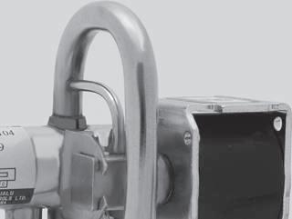
Ambient humidity: Less than 95% R.H.
TYPE NUMBER SELECTION
Catalog No.
Size (mm)
Type
VALVES
Type
Type STF–25,
Capacity (R410A)
STF–H0104 8 1.8 to 6.4 0.51 to 1.82
STF–H0202 11.1 2.0 to 11.4 0.57 to 3.24
STF–H0301 11.5 5.3 to 14.6 1.50 to 4.15
(MPa) {kgf/cm
Connection (O.D.) Wt. (kW)(kg) (U.S.R.T.)
Min. Discharge Suction & Coils
5/16" 3/8" 0.2
3/8" 1/2" 0.32
1/2" 5/8" 0.37
STF–H0404 16 8.3 to 33 2.36 to 9.39 3/4" 0.77
STF–H0601 18.1 8.4 to 45 2.39 to 12.8 0.87
STF–H0712 20 21 to 53 5.97 to 15.0
3/4" 7/8" 1.2
STF–H0901 21.3 21 to 68.5 5.97 to 19.5 1.23
STF–1511G 23 39 to 59 11.1 to 16.7
STF–2023G 24 39 to 74 11.1 to 21.0
STF–2501G
STF–3001G
STF–4001G
STF–5001G
STF–6001G
52 to 94 14.8 to 26.7
65 to 124 18.5 to 35.2
115 to 188 32.7 to 53.4
{31.6} 0.3 {3.1}
1–1/8" 1.55
1" 1–1/4" 3.4
1–1/2" 4.7
1–3/4" 9.1
145 to 235 41.2 to 66.8 2–1/8" 9.4
230 to 360 65.4 to 102
1–5/8" 2–5/8" 20.0
88
REVERSING
High Volume OEM Item (Type STF) Type STF
•
4-way reversing valves are suitable for heat pump applications on unitary, split system and window type air conditioners, etc. • 4-way pilot valve adoption has an advantage on reliable changeover operations. • D e s i g n e d t o l o w e r t h e m i n i m u m o p e r a t i n g p r e s s u r e di ffe re nce be tw ee n hi gh an d lo w si de P res su re d ro p and valve leakage are minimized.
•
2}
****)
2}
****
•
•
•
mark
request)
request)
STF–H01,H02
STF–H04, H07
30, 40, 50, 60 ・・O.P.D.: Operating Pressure Differential (with air) High Volume OEM Item
Port
O.P.D.
2}
Max.
3.1
7/8"
28
34
1–1/4"
40
1–1/2"
50
60
I.D.
Type STF–H06,H09 Correo: xbombas@gmail.com Telefono: 55 5378 7190
100V.
220V.
230V. AC 240V.
100V.
200V.
220V. AC
AC 240V. AC
33/27
89 DIMENSIONS (92)[(118)] 12[ 16 ] 12[ 16 ] 21.7φ [ 26.5 ] 50 [ 59 ] 62 [ 71 ] 62 [ 68 ] 42.5 [ 51 ] 42[ 52 ] D C S E M5 M5 M5 M5 M4 M4 16 25 25 (42) 26.5φ 87 62 52 (118) D S E C (15(15°) °) 2929[33.5] [33.5] 95 [ 98.5 ] (181.5)[(212)] 83 [ 85.7 ] 67 [ 82 ] 39.6 φ3 6 [ 45 ] 35.5[40] D E S C 39.6 6 7 [ 82 ] 95 [ 98.5 ] 83 [ 85.7 ] (188)[(214.4)] φ3 6 [ 45 ] 29[ 33.5 ] 29[ 33.5 ] 35.5[ 40 ] E S C D (224) φ4 5 43.5 144 100 50 50 41.5 D φ4 5 (244) 37 37 43.5 96 109 91 S D E C E S C 41.5 Type STF–H0104 [H0202] Type STF–H0404 [H0712] Type STF–H0301 Type STF–H0601 [H0901] Type STF–1511G Type STF–2023G Unit: mm * IEC compliance ELECTRICAL RATING OF SOLENOID COILS Catalog No. Rated Voltage Tolerance (%) Voltampere(VA) Power Consumption (W) Insulation Class Running Inrush STF–H ****
AC 200V. AC 50/60Hz +10 –15 10/8 30/24 6/5 Class B Molded 110V. AC
AC +10 –10
AC 11/9 33/27 STF– **** G
AC
AC 50/60Hz +10 –15 13/10 39/30 7/6 110V. AC
+10 –10 11/9
230V.6/6
* Correo: xbombas@gmail.com Telefono: 55 5378 7190
90 D E S C 5858 30 φ82001668 149 169 * 136 81 63 (414) *STF‒5001G: 202 226 230 40 φ61421206 120 145 121 39 76 D E S C 4949 (347) 40 260 300 220 E S C (526) 75 75 184 240 82.5 D 33 103 (195.5) 158 116φ M4 M4 M4 Type STF–3001G Type STF–4001G, –5001G Type STF–6001G Unit: mm FLOW RATE (Capacity) STF-1501G STF-H0712 STF-H0901 STF-H0601 STF-H0404 0.001 0.005 0.01 0.04 1 5 10 50 100 500 STF-5001G STF-4001G STF-3001G STF-2501G STF-2023G STF-H0301 STF-H0202 (kCapacitySTF-H0104 W ) Suction Pressure Drop MPa Refrigerant: R410A Kw USRT 0.1 0.5 1 5 PSI MPa 1 0.5 0.3 2 10 15 4 6 8 20 40 30 50 100 STF-6001G STF-5001G STF-4001G STF-3001G STF-2501G STF-1501G STF-2023G STF-H0712 STF-H0901 STF-H0601 STF-H0404 STF-H0301 STF-H0202 STF-H0104 500 100 50 10 5 1 Capacity (k W ) Refrigerant: R22,R407C STF-6001G Kw USRT 0.001 0.005 0.01 0.04 Suction Pressure Drop MPa 0.1 0.5 1 5 PSI MPa 1 0.5 0.3 2 10 15 4 6 8 20 40 30 50 100 * Flow Rate Conditions Condensing temp.: 38°C Evaporator temp.: 5°C Superheat temp.: 5°C D E S C 5858 30 φ82001668 149 169 * 136 81 63 (414) *STF‒5001G: 202 226 230 40 φ61421206 120 145 121 39 76 D E S C 4949 (347) 40 260 300 220 E S C (526) 75 75 184 240 82.5 D 33 103 (195.5) 158 116φ M4 M4 M4 Type STF–2501G D E S C 45 45 (311) (76) 111 117131 φ6 1 M4 Correo: xbombas@gmail.com Telefono: 55 5378 7190
Type MJV

MOTORIZED BALL
SPECIFICATIONS
TYPE NUMBER SELECTION
Two-way
91
VALVES
GENERAL DESCRIPTION • Proportional Control valve for hot or chilled water, industrial water and steam circuit. • Compact & Light weight design, manual operation is also available. • Various types of water supply Equipments • Air Handling Units • Ice Storage Units Type MJV
Valve Catalog No. Connection Rc (O.D.) Cv Value Max. Operation Press. Differential (MPa) Connection Fastening Torque (N・m) Dimension Wt. (kg)Type Model Input Signal H L D MJV–1504GQ1 70 (Resistance 0 to 135Ω) 71 (4 to 20 mA) 72 (1 to 5 VDC) 73 (0 to 10 VDC) 1/2" 1 1 34.3 152 56 32 1.51504GQ2 2 1504G 3.5 2006G 3/4" 6.5 49 155 69 42 1.7 2510G 1" 12 58.8 159 82 50 1.9 3212G 1–1/4" 20 0.8 78.5 165 97 60 2.6 4014G 1–1/2" 30 0.6 83.4 178 106 71 3.2 5020G 2" 45 0.4 98.1 185 128 84 4.6 Two-way Valve for Steam Catalog No. Connection Rc (O.D.) Cv Value Max. Operation Press. Differential (MPa) Connection Fastening Torque (N・m) Dimension Wt. (kg)Type Model Input Signal H L D MJV–H1504GQ1 70 (Resistance 0 to 135Ω) 71 (4 to 20 mA) 72 (1 to 5 VDC) 73 (0 to 10 VDC) 1/2" 1 1 34.3 202 56 32 1.8H1504GQ2 2 H1504G 3.5 H2006G 3/4" 6.5 49 205 69 42 2.0 H2510G 1" 12 58.8 209 82 50 2.2
Valve Type Item Two-way Valve Two-way Valve for Steam Three-way Valve Water Test Pressure 1.6MPa Air Tight Pressure 1.6MPa Max. Working Pressure 1.6MPa (0.2MPa for Steam) 1.6MPa (0.5MPa for Steam) 1.6MPa Fluid Non-corrosive water and Steam Non-corrosive water Fluid Temperature 0 to 120°C 0 to 160°C 0 to 90°C Flow Characteristics Equal Percentage Corrected Linear Valve Leakage Cv: 0.1% or less Material Body: Bronze Casting, Seat Ring: Fluoro-resin, O-ring: Fluoro rubber, Spindle: Stainless Steel, Plug: Stainless Steel Power Supply Voltage 24V.AC±10%, 50/60Hz Max. power Consumption 12VA Housing Construction Rain-Proof (JIS C 0920 IP53) Ambient Temperature Operating Temp.: 10 to 50°C, Storage Temp.: 20 to 70°C Timing Approx. 52 sec. Resistance Input 0 to 135Ω Current Input DC 4 to 20mA (Input Impedance 250Ω) Voltage Input DC 1 to 5V (Input Impedance 100kΩ), DC 0 to 10V (Input Impedance 250kΩ) Material Case: PPS Resin, Cover: ABS Resin Manual Operation Yes Flow Display O: Open, S: Close O: Open(C→A), S: Close(C→A) Movement of Valve Input Signal 135Ω・4mA・1V・0V:Close Input Signal 135Ω・4mA・1V・0V: Close(C→A) V AL VE P AR T MOTOR P AR T INPUT SIGNAL Correo: xbombas@gmail.com Telefono: 55 5378 7190
WIRING
M1504G
M2006G
M4014G
Input Current Input
DIMENSIONS
Manual Operation
Input
Mounting Position
92
Mounting position should be in the below range. Flow Opening Indicator Label Shaft for Manual Operation Clutch Release Button for Manual Operation Flow Direction display 0.3mm Cab tire code (130) (100) (5) 116 1000 2-Rc D L (11) (H) 90 6 S Opening Indicator Label Shaft for Manual Operation Clutch Release Button for Manual Operation Flow Direction display 0.3mm Cab tire code (130) (100) (5) 116 1000 3-Rc D L (11) (H1) (B)(H2) (C) Flow Mixed(A) Flow 90 6 S Flow Opening Indicator Label Shaft for Manual Operation Clutch Release Button for Manual Operation Flow Direction display 0.3mm Cab tire code (130) (100) (5) 116 1000 2-Rc D L (11) (H) 90 6 S Opening Indicator : O...Open, S...Close 9090° ° 9090° ° Two-way Valve Three-way Valve Two-way Valve for Steam
• Use a spanner at Manual Operation shaft (Torque:3N・m), with pushing a Clutch Release Button. Manual operation can be carried out by rotating the shaft. Don't operate in energized position for the safty please do not operate it by any means. Three-way Valve Unit: mm Resistance
Voltage
(Blue)COM. (Brown)0 to 135Ω (Black) (Red) Input Supply Voltage 24V.AC (Blue)COM. (Brown)4 to 20mA (Black) (Red) Input Supply Voltage 24V.AC (Blue)COM. (Brown)1 to 5V , 0 to 10V (Black) (Red) Input Supply Voltage 24V.AC
Catalog No. Connection Rc (O.D.) Cv Value Max. Operation Press. Differential (MPa) Connection Fastening Torque (N m) Dimension Wt. (kg)Type Model Input Signal H1 H2 H2 L MJV–
70 (Resistance 0 to 135Ω) 71 (4 to 20 mA) 72 (1 to 5 VDC) 73 (0 to 10 VDC) 1/2" 3.5 0.1 34.3 152 30 56 32 1.6
3/4" 6.5 49 155 37 69 42 1.8 M2510G 1" 12 58.8 159 44 82 50 2.1 M3212G 1–1/4" 20 78.5 165 51 97 60 2.8
1–1/2" 30 83.4 178 57 106 71 3.5 M5020G 2" 45 98.1 185 67 128 84 5.0 Correo: xbombas@gmail.com Telefono: 55 5378 7190
DAMPER & VALVE MOTOR ACTUATORS

Type EGK & WGK
GENERAL DESCRIPTION
• Series GK motor actuator can provide On-Off, propor tional or floating control of damper, valve or other con trolling devices.
• Balancing relay without contact causes no bur n-out.

• Type EGK is for damper Type WGK is for valve.
Power requirement: 24V. AC ±10%, 50/60Hz
Max. power consumption: 21VA (without spring retur n action) 24VA (with spring retur n action)
Input signal: resistance 0 to 135Ω
Current 4 to 20mA. DC (Input Impedance 250Ω)
Voltage 1 to 5V DC (Input Impedance 100kΩ)
Type: EGK
Torque: 12.2N·m {1.25 kg·m} (without spring retur n action) 3.9N·m {0.4 kg·m} (with spring retur n action)
Rotation angle: 90 to 270° (without spring retur n action) 90 to 160° (with spring retur n action)
Delivery Setting 90°
Timing: 80 sec/160°
Ambient temp.: 20 to 55°C (without spring retur n action) 10 to 55°C (with spring retur n action)
Weight: 4.3kg (without spring retur n action) 6.1kg (with spring retur n action)
DAMPER MOTOR SELECTION
VALVE MOTOR SELECTION
Type: WGK
Thrust: 1220N {125 kgf} (without spring retur n action) 390N {40 kgf} (with spring retur n action)
Stroke: 14 to 50mm (without spring retur n action) 14 to 30mm (with spring retur n action)
Delivery Setting 20mm
Timing: 80 sec/stroke 25mm
Ambient temp.: 20 to 55°C (without spring retur n action) 10 to 55°C (with spring retur n action)
Weight: 5kg (without spring retur n action) 6.7kg (with spring retur n action)
93
Type EGK
Type WGK
* 1. The motor actuates with On-Off or floating signal from sensor. * 2. The motor actuates with proportional signal from electronic sensor (Example: Type RBE Control Unit). * 3. The motor actuates with the signal between 0 and 135Ω from electric sensor (Example: Type PWS Thermostat). * 4. Spring Return Type is so designed that actuator shaft returns to safe side on current failure. Auxiliary potentiometer is to provide the signal between 0 and 135Ω in accordance with motor angular rotation for output. Auxiliary switch provides the contact signal of S.P.D.T. for output. Enclosure: IP62
TYPE NUMBER SELECTION (SPECIFICATIONS) Function Model On-Off / Floating Control Without Positioning Balance Relay With Positioning Balance Relay With Positioning Balance Relay On-Off / Floating On-Off Servo Resistance Input Current Input Voltage Input Standard WGK–N500A WGK–N600 A/S WGK–N700 A/S WGK–N701 A/S WGK–N702 A/S With Auxiliary Potentiometer WGK–N610 A/S WGK–N710 A/S WGK–N711 A/S WGK–N712 A/S With Auxiliary Switch WGK–N520A WGK–N620 A/S WGK–N720 A/S WGK–N721 A/S WGK–N722 A/S Function Model On-Off / Floating Control Without Positioning Balance Relay With Positioning Balance Relay With Positioning Balance Relay On-Off / Floating On-Off Servo Resistance Input Current Input Voltage Input Standard EGK–N500A EGK–N600 A/S EGK–N700 A/S EGK–N701 A/S EGK–N702 A/S With Auxiliary Potentiometer EGK–N610 A/S EGK–N710 A/S EGK–N711 A/S EGK–N712 A/S With Auxiliary Switch EGK–N520A EGK–N620 A/S EGK–N720 A/S EGK–N721 A/S EGK–N722 A/S *4*3*2 *1 *2 *3 *4 *1 Correo: xbombas@gmail.com Telefono: 55 5378 7190
94 INTERNAL WIRINGS • Check power supply to be 24V AC ±10%. • Wiring is to be based on the technical standard of electrical installation. Be assured to use covered copper wire larger than 1.2 mm dia. • Terminal wiring should be conducted with flexible wire of adequate length to prevent wire disconnection from slight move of the motor. 24V. AC Input Signal 4 to 20 mA. DC COM Auxiliary Potentiometer Auxiliary Switch 1 to 5 V. DC Proportional Controller (0 to 135Ω) d a e g f b c 8 9 1 3 7 6 24V. AC d a e g f b c 9 8 1 2 7 4 6 10 11 5 10 11 5 S R V.I + + On-Off or Floating Controller On-Off Servo Signal Feedback Resistance 24V. AC 24V. AC 9 8 c b 7 6 a d d a e f b c 9 8 2 4 3 1 7 6 EGK–N500A, WGK–N500A EGK–N600A/S, WGK–N600A/S Type EGK–N A Type EGK–N S EGK–N700A/S, WGK–N700A/S EGK–N701A/S, N702A/S, WGK–N701A/S, N702A/S a : Upper Limit Switch b: Lower Limit Switch c : Cam d: Condenser Motor e : Feedback Potentiometer f : Spring Return Releasing Magnet g : Balance Relay Terminals Motor Inter nal Wiring Motor Exter nal Wiring Spring Retur n Type Only EGK–N □ 1 □ A/S WGK–N □ 1 □ A/S EGK–N □ 2 □ A/S WGK–N □ 2 □ A/S DIMENSIONS 122 130 8.5 210 95 10 36 34 150 130 φ34.5 150 198 27171 122 187 322 210 1095 112 187 80.5 2 φ27 with Plastic Cap 2 φ27 with Plastic Cap 2 φ11 Mounting Hole Hole for adjusting Rotation Hole for adjusting Stroke 122 130 8.5 210 95 10 36 34 150 259 80.5 2 φ27 with Plastic Cap 2 φ11 Mounting Hole Hole for adjusting Rotation Valve Opening Position Indicator 130 φ34.5 150 270 27 122 187 322 210 1095 112 2 φ27 with Plastic Cap Hole for adjusting Stroke Valve Opening Position Indicator Type WGK–N SType WGK–N A Correo: xbombas@gmail.com Telefono: 55 5378 7190
2-WAY & 3-WAY CONTROL VALVES
Type NVK GENERAL DESCRIPTION
WGK
non-corrosive
2-way valve
2-way
3-way valve
model
V-port
pressure
seated
seated
linear
TYPE NUMBER SELECTION (SPECIFICATIONS)
NVK 2-way valve
Connection
Fluid
Max. Working Press.
Fluid Temp. (°C)
Flow Characteristic
kgf/cm
200
Flange (JIS 10K)
Water and Steam
Equal Percentage
Flange (JIS 10K)
0.98MPa {10 kgf/cm
to 200
Material of Body CAC406 FC200 FC200
Material of Plug SCS14
Material of Seat Ring SUS316 Material of Stem SUS304
Type NVK–M 3-way valve


Connection
Fluid
Max. Working Press.
Fluid Temp. (°C)
Flow Characteristic
Water
Flange
10K)
conditioning
{10 kgf/cm
200
Equal Percentage
Material of Body CAC406 FC200
Material of Plug SCS14
Material of Seat Ring SUS316
Material of Stem SUS304
95
• Ty p e N VK c on tr ol va l ve s a r e a cc om p an ie d b y Saginomiya type
motor for two position (On-Off), floating or proportional control. • For use with low or high
hot and chilled water or
fluid. • NVK
(single
type) NVK–W
valve (double
type) NVK–M
(mixing valve) • Wide
selection available for various applications. •
plug provides almost
flow characteristic.
Type
Type
NVK–G Type NVK–F Model Item NVK—M **** GL NVK—M **** FL
Rc
(JIS
Non-corrosive
for Air
0.98MPa
2}
0 to
Model Item NVK— **** GL NVK— **** FL NVK W **** FL
Rc
Non-corrosive
0.98MPa {10
2}
2}
0 to
0
Correo: xbombas@gmail.com Telefono: 55 5378 7190
NVK–
20 3/4"
25 1"
NVK–W
43 28 0.9
0.66 {6.7}
0.38 {3.9} 0.95
0.98 {10}
0.24 {2.4} 90 48 29 1.2
3212GL 32 1–1/4" 20 0.95 {9.7} 0.14 {1.4} 105 50 30 1.6
4014GL 40 1–1/2" 30 0.61 {6.2} 0.09 {0.9} 120 60 35 2.4
5020GL 50 2" 45 0.40 {4.1} 0.05 {0.5} 0.67 {6.8} 140 68 46 3.6
6524FL 65 2–1/2" Flange (JIS 10K)
70 30 0.28 {2.9} 0.044 {0.45} 0.48 {4.9} 276 125 87.5 19.9
8030FL 80 3" 110 0.19 {1.9} 0.028 {0.29} 0.31 {3.2} 298 149 92.5 25
10040FL 100 4" 180 40 0.12 {1.2} 0.2 {2} 352 169 105 36
4014FL 30
0.98 {10} 222 110 70 10.5
5020FL 50 2" 45 254 114 (80) 13.5
6524FL 65 2–1/2" 70 30 0.81 {8.3} 276 129 (96) 18
4014FL@1 40 1–1/2" Flange (JIS 10K)
20 20 0.98 {10}
8030FL 80 3" 110 0.66 {6.7} 298 156 (115) 28.5
10040FL 100 4" 180 40 352 187 (150) 46.5
12550FL 125 5" 260 403 208 (153) 63.3
15060FL 150 6" 380 451 225 (170) 90.6
20080FL 200 8" 630 45 0.69 {7} 543 278 (212) 167
250100FL 250 10" 960 0.49 {5} 673 319 (232) 251
96 Type NVK 2-way valve Cv Flow (L/min) passing through the valve at full opening when water temperature is 15°C and pressure difference across the valve is 0.00048 MPa {0.0049 kgf/cm2} The dimension value bracketed off by ( ) shows "h2" value due to "h2" value being bigger than the one of "h". L h H H h h2 L M8×1 90 90 M8×1 Stroke Stroke DIMENSIONS Unit: mm Type NVK–G Type NVK–F, WF Catalog No. Port Size (mm) Connection Cv Value Stroke (mm) Close off Rating MPa {kgf/cm2} Dimensions (mm) Wt. T(kg) ube O.D. Style WGK–N*A WGK–N*S WGK–N*L L H h (h2)
1504GL@1 15 1/2" Rc 1 20 0.98 {10} 0.98 {10}
80
1504GL@2 2.5 1504GL 5
2006GL
8
2510GL
12
H h h2 L M8×1 90 Stroke Correo: xbombas@gmail.com Telefono: 55 5378 7190
NVK–M
15 1/2"
20 3/4"
2510GL 25 1"
3212GL 32 1–1/4"
{10} 0.38 {3.9} 0.98 {10}
80 29 72 1.1
73 1.12
0.23 {2.3} 90 32 77 1.45
0.95 {9.7} 0.14 {1.4} 105 38 80 1.95
4014GL 40 1–1/2" 30 0.61 {6.2} 0.09 {0.9} 120 43 84 2.7
5020GL 50 2" 45 0.40 {4.1} 0.061 {0.62} 0.67 {6.8} 140 51 97 4.17
6524FL 65 2 1/2"
70 30 0.28 {2.9} 0.044 {0.45} 0.48 {4.9} 276 92 185 24.5
8030FL 80 3" 110 0.19 {1.9} 0.028 {0.29} 0.31 {3.2} 298 106 215 31
Flange (JIS 10K)
12550FL 125 5" 260 0.08 {0.8} 0.13 {1.3} 403 149 263 64.5
10040FL 100 4" 180 40 0.12 {1.2} 0.2 {2} 352 131 238 42
15060FL 150 6" 380 0.05 {0.5} 0.09 {0.9} 451 173 288 92
DIMENSIONS
97 Type NVK 3-way valve (used as a mixing valve) M8×1 L h H 90 Stroke Stroke M8×1 h H 90 L ・ Cv Flow (L/min) passing through the valve at full opening when water temperature is 15°C and pressure difference across the valve is 0.00048 MPa {0.0049 kgf/cm2}
Unit: mm Type NVK–MG Type NVK–MF Catalog No. Port Size (mm) Connection Cv Value Stroke (mm) Close off Rating MPa {kgf/cm2} Dimension (mm) Wt. T(kg) ube O.D. Style WGK–N*A WGK–N*S WGK–N*L L H h
1504GL
Rc 5 20 0.98
2006GL
8
12
20
Correo: xbombas@gmail.com Telefono: 55 5378 7190
OTHER VALVES
CHECK VALVES 99 Type ACV & BCV
PRESSURE ACTUATED WATER REGULATING VALVES 100 Type VWR
PRESSURE ACTUATED WATER REGULATING VALVES
101–102 Type CWR, AWR, GWR, MWR & SWR
TEMPERATURE ACTUATED WATER REGULATING VALVES 103–104 Type OWR, HWR & XWR
PRESSURE REGULATING VALVES 105–106 Type EPR
PRESSURE REGULATING VALVES
107–108 Type SPR & DPR PRESSURE REGULATING VALVES 109–110 Type HPR
DIAPHRAGM TYPE STOP VALVES 111 Type ADV BELLOWS TYPE STOP VALVES 112–113 Type NBV
・・
・・・・・・・・・・・
OTHER V AL VES
Correo: xbombas@gmail.com Telefono: 55 5378 7190
Type
&
CHECK VALVES
Catalog
ACV–2B (D)
ACV–3B (D)
ACV–4B (D)
liquid
counter flow
Fluid
heat pump
reverse flow
pressure
Pressure
Refrigerants
0.55 1/4"
1 3/8"
Temp.
(kg)
0.05
0.1
2.4 1/2" 0.4 0.2
to 125
{30.6}
ACV–5B (D) 12.5 4.2 5/8" 0.5 0.3
Gas
ACV–6B (D)
6 3/4"
Catalog No. Fluid Port Size (mm) Cv Value Connection
BCV–302DY
0.5
Allowable Liquid Temp. (℃) Wt. (kg) Copper Tube (I.D.) Style
3 0.33 1/4"
Max. Working Pressure (MPa) {kgf/cm
0.02
BCV–603DY 5.5 0.97 3/8" 0.04
BCV–804DY 8 2 1/2" 0.07


Fluorinated Refrigerants
Solder 4.15 {42.3} 30 to 120
BCV–1005DY 10 3.5 5/8" 0.14
BCV–1306DY 12.5 4.7 3/4" 0.18
BCV–1810DY 18 8 1" 0.34
DIMENSIONS
Catalog No.
ACV–2B
Type
BCV–302DY
Catalog No.
BCV–302DY
BCV–603DY
BCV–804DY
BCV–1005DY
BCV–1306DY
BCV–1810DY
6.55
9.71
12.93
16.12
19.30
25.7
99
ACV
BCV GENERAL DESCRIPTION • Install in the
line of
air conditioner to prevent the
at change over of cycles from heating to cooling and vice versa. • Also for prevention of
of high
gas when compressor stops. • For use with Fluorinated Refrigerants, and Inert Gas. • Can be mounted in horizontal or vertical line. • Valve material : Fluorocarbon resin Type ACV–B TYPE NUMBER SELECTION (SPECIFICATIONS) Type ACV Type BCV Type ACV
L S φD L φd L E L E φ d Type ACV–B Type ACV–D Type
to 804DY Type BCV–1005DY to 1810DY
BCV Unit: mm Type BCV
No.
Port Size (mm) Cv Value Connection Max. Working
(MPa) {kgf/cm2} Allowable Liquid
(℃ ) Wt.
Copper Tube (O.D.) Style B D
Fluorinated
Air Inert
4.8
B: Flare D: Solder 3
40
0.1
7.5
0.2
10
16
0.7
2}
Unit: mm L φD S
58 14 ACV–3B 76 19 ACV–4B 87 24 ACV–5B 103 30 ACV–6B 115 36 ACV–2D 120 6.35 ACV–3D 160 9.53 ACV–4D 187 12.70 ACV–5D 235 15.88 ACV–6D 300 19.05
Unit: mm L φD E
112
120
8
140
13
160
16
180
19
200
20 ・ Standard valve material of BCV-1005DY is Polyamide resin. Correo: xbombas@gmail.com Telefono: 55 5378 7190
ACTUATED WATER REGULATING VALVES
Type VWR
GENERAL DESCRIPTION
Type VWR: 2-way press. actuated water regulating valves,open on pressure increase.

Refrigerant: R410A, R407C, R404A
Type VWR is applicable to the adjustment range which
the applicable adjustment range of type AWR (Refer to next page).
Pressure connection: 1/4" flare nut (Standard)
Body material: Bronze for water and glycol.
FLOW CAPACITY
Capacity shows r espectively r efrigeration pr ess. dif f. at horizontal axis and flow rate of cooling water at vertical axis
water press. diff. before and behind a valve with 0.1 MPa. (press. diff. between inlet and outlet of valve)
case of water press. diff. before and behind a valve is excepting for 0.1MPa, value is calculated multipling by coef ficient in compensation table.
ADJUSTMENT
COMPENSATION COEFFICIENTS
DIMENSIONS
100 PRESSURE
•
•
•
exceeds
•
•
Flow
considering
In
One full tur n of adjusting screw changes pressure setting as shown below ) H ( ) h ( L □C Inlet 1/4" Flare Nut D (Hex.Width across flats) 10 0 1 0 2 0 3 0 4 0 5 0 6 0 7 0.8 20 30 40 50 5 100 (L/min) Flow volume Valve Opening Press.(Gas pressure when valve opening) Please avoid to apply to this range constantly Valve(MPa) Opening Refrigeration Press Valve Opening Refrigerant Press. Diff. means difference between valve opening press.(Setting Press.) and actual working press 1203G 2006G 1504G TYPE NUMBER SELECTION (SPECIFICATIONS) PRESSURE ACTUATED VALVES 2-WAY * Pressure at which valve starts opening. ・ Adjust type VWR to a set value which is suitable for the refrigerant employed. water pressure difference before and behind a valve: 0.1MPa
Unit: MPa {kgf/cm2} Catalog No. Kind of Refrigerant Valve Body Material Connection Press. Range Max. Working Press. Max. Water Temp.(°C) Max. Water Press. Factory Setting Wt. Size(kg) Style VWR–1203G Fluorinated Refrigerants Bronze 3/8" Rc 1.5 to 2.9 {15.3 to 29.6} 4.2 {42.8} 60 1 {10.2} 2.4 {24.5} 0.68 1504G 1/2" 0.9 2006G 3/4" 1.0 Catalog No. Change in Press. Setting VWR–1203G Approx. 0.2MPa1504G 2006G Press. Drop Across Valve: MPa {kgf/cm2} Coefficient 0 2 {2} 1 4 0 1 {1} 1 0 0 3 {0 3} 0.55 0 0 5 {0 5} 0.7 0 07 {0 7 } 0.8 Catalog No. Unit: mm D L H h □ C VWR–1203G 22 55 91 72 40 1504G 27 70 100 83 42 2006G 32 80 104 87 * Correo: xbombas@gmail.com Telefono: 55 5378 7190
FLOW CAPACITY
Press. Drop
Catalog No.
AWR–1204BLW 100 90 70 40 1203GLW 22 55 91 72
AWR–GWR–
AWR–MWR–GWR–
1504GLW 27 70 100 83 42 2006GLW 32 80 104 87 2510GLW 40 90 116 97 593212GLW 50 100 121 102
4014FLW 148 125 105 5020FLW 173 180 155 89 6524FLW 179
SWR–
1504GLW 27 70 100 31 114 42 2006GLW 32 80 104 39 126 2510GLW 40 90 116 44 141 59 3212GLW 50 100 121 54 156
102 ACCESSORY • Pressure dampening capillary tube assembly only attached for AWR–50, –65, MWR–50 and –65. Please use these for safty COMPENSATION COEFFICIENTS DIMENSIONS 50 Capillary Tube Approx. 1m Shrader Connection 1/4" Flare Nut (φ23.9) Rc3/8 (46) (21) 33 (79) φ22 Hex. 24 Inlet (h) (H) (h 1 ) □C L (Main) InletOutlet 1/4" Flare Nut D (Hex. width across flats) L (Bypass) Outlet Blind Plug (H) (h) L □C Inlet 1/4" Flare Nut D (Hex. width across flats) (h) (H) □C Inlet L 1/4" Flare Nut Type CWR 1/4" Flare Nut Union 1 meter Capillary Tube. Unit: mm Type AWR–F, MWR–F, TGWR–F ype AWR–G, GWR–G Type SWR
Flow Capacity shows respectively refrigeration press. diff. at horizontal axis and flow rate of cooling water at vertical axis considering water press. diff. before and behind a valve with 0.1 MPa. (press. diff. between inlet and outlet of valve) In case of water press. diff. before and behind a valve is excepting for 0.1MPa, value is calculated multipling by coefficient in compensation table. Type AWR, MWR, GWR water pressure difference before and behind a valve: 0.1MPa Type SWR water pressure difference before and behind a valve: 0.1MPa Flow volume (MPa) Bypass side Main side Setting Range(Point)(Valve Opening Press) Please avoid to apply to this range constantly. Press. Diff. between Valve Opening Setting Press. and Refrigerant Press.(Gas Press inside Bellows) Flow volume (MPa) Valve Opening Press.(Gas pressure when valve opening) Please avoid to apply to this range constantly. Valve Opening Refrigeration Press. Valve Opening Refrigerant Press. Diff. means difference between valve opening press.(Setting Press.) and actual working press. 0.1 0.2 0.3 0.4
Across Valve: MPa {kgf/cm2} Coefficient 0.2 {2} 1.4 0.1 {1} 1 0.03 {0.3} 0.55 0.05 {0.5} 0.7 0.07 {0.7} 0.8
Unit: mm D L H h h1 □C
Correo: xbombas@gmail.com Telefono: 55 5378 7190
OWR,
&
GENERAL DESCRIPTION
W
TYPE NUMBER SELECTION (SPECIFICATIONS)
WATER REGULATING VALVES


XWR–
1.2
2.0 5012G 1–1/4" 2.2
5010G
5014F
Cast Iron 1–1/2"
11.5 5020F 2"
18.3 5024F 2–1/2" 22.2
P7504G Bronze
1/2"
150
1.0 P7506G 3/4" 1.2 P7510G 1"
19
320 2.0
P7512G 1–1/4" 2.2
P7514F Cast Iron 1–1/2"
11.5 P7520F 2"
18.3 P7524F 2–1/2" 22.2
1/2"
5006G 3/4"
5004G Bronze
VALVE ACTION
ADJUSTMENT
103
TEMPERATURE ACTUATED VALVES 2-WAY TEMPERATURE ACTUATED
Type
HWR
XWR
• Type OWR : 2-way temp. actuated water regulating valves, open on temperature increase. Type H
R: 2-way temp. actuated water regulating valves, open on temperature decrease. Type X W R : 3-way temp actuated water regulating valves. • Temperature sensing element (Bulb) • Body material: Bronze for water and glycol, cast iron for water only TEMPERATURE ACTUATED VALVES 3-WAY * Pressure at which valve starts opening. ・ OWR & HWR with flange connection are supplied with JIS 10K (0.98 MPa) round companion flanges (JIS B2220 2239) and bolt/nuts. ・ Capillary tube Standard φ24mm × 1 meter, optional 1.5, 2 and 3 meters * Pressure at which valve starts opening. ・ Capillary tube Standard φ24mm × 1 meter, optional 1.5, 2 and 3 meters Unit: °C Unit: °C Type OWR Type XWR Temp. Set Point OWR HWR XWR Main Line Bypass Line Temp. Set Point Flow Flow Temp. Set Point Flow
Set Point is pressure for valve opening. Each cheractaristic of valves is different as follows.
One full tur n of adjusting scr ew changes temperature setting as shown below Catalog No. Valve Body Material Connection Temp. Range Max. Water Temp. Max. Water Press. MPa {kgf/cm2}} Max. Bulb Temp. Bulb Size (mm) Factory Setting Wt. Size(kg) Style OWR–HWR–5004G Bronze 1/2" Rc 30 to 50 60 0.98 {10} 80 φ19×150 40 1.0 5006G 3/4"
1" φ19×320
Flange
φ32×350
Rc 50 to 75 100 φ19×
60
φ
×
Flange
φ32×350
Catalog No. Valve Body Material Connection Temp. Range Max. Water Temp. Max. Water Press. MPa {kgf/cm2}} Max. Bulb Temp. Bulb Size (mm) Factory Setting Wt. Size(kg) Style
Rc 30 to 50 60 0.9 8 {10} 80 φ19×150 40 1 0
1 5 5010G 1" φ19×320 2.5 5012G 1 1/4" 3.0 P7504G 1/2" 50 to 75 100 φ19×150 60 1.1 P7506G 3/4" 1 5 P7510G 1" φ19×320 2.5 P7512G 1 1/4" 3.0 Catalog No. Change in Temp. Setting OWR–HWR–XWR–** 04G Approx. 4.0°C ** 06G ** 10G Approx. 3.0°C** 12G OWR–HWR–** 14F ** 20F Approx. 4.0°C ** 24F * * Correo: xbombas@gmail.com Telefono: 55 5378 7190
COMPENSATION COEFFICIENTS
Catalog No.
5004G 27 70 100 83 42
5006G 32 80 104 87
5010G 40 90 116 97
5012G 50 100 121 102
5014F 148 125 105
5020F 173 180 155 89 5024F 179
OWR–
P7504G 27 70 100 83 42
P7506G 32 80 104 87
P7510G 40 90 116 97 59
P7512G 50 100 121 102
P7514F 148 125 106
P7520F 173 180 155 89
P7524F 179
Catalog No.
mm
5004G 27 70 100 31 114
5006G 32 80 104 39 126
5010G 40 90 116 44 141 59
5012G 50 100 121 54 156
XWR–
P7504G 27 70 100 31 114
P7506G 32 80 104 39 126
P7510G 40 90 116 44 141 59
P7512G 50 100 121 54 156
104 DIMENSIONS Inlet D (Hex. width across flats) φ2.4×1000 Capillary Tube (h) (H) L □C φ2.4×1000 Capillary Tube Inlet (h) (H) □C 14F 20F, 24F L Inlet D (Hex. width across flats) (Main) Outlet (h) (h1) (H) L □C Blind Plug φ2.4×1000 Capillary Tube (Bypass) Outlet Type OWR–G, HWR–G Type XWR Type OWR–F, HWR–F Unit: mm
FLOW CAPACITY Flow Capacity shows respectively opening temp. diff. at horizontal axis and flow rate of cooling water at vertical axis considering water press. diff. before and behind a valve with 0.1 MPa. (press. diff. between inlet and outlet of valve) In case of water press. diff. before and behind a valve is excepting for 0.1MPa, value is calculated multipling by coefficient in compensation table. Type OWR, HWR water pressure difference before and behind a valve: 0.1MPa Type XWR water pressure difference before and behind a valve: 0.1MPa Bypass side Connection SizeConnection Size Main side Connection Size Flow volumeFlow volume (℃) 30 Valve Opening Temp. Please avoid to apply to this range constantly. Please avoid to apply to this range constantly. Valve Opening Temp. Valve Opening Temp. Diff. (℃)Valve Opening Temp. Diff. 1-1/4” 3/4” 1/2” 1” 1-1/4” 3/4” 1/2” 1” 1-1/4” 3/4” 1/2” 1” 1-1/2” 2-1/2” 2” Press. Drop Across Valve: MPa {kgf/cm2} Coefficient 0.2 {2} 1.4 0.1 {1} 1 0.03 {0.3} 0.55 0.05 {0.5} 0.7 0.07 {0.7} 0.8
Unit: mm D L H h □C
HWR–
59
Unit:
D L H h h1 □C
42
42
Correo: xbombas@gmail.com Telefono: 55 5378 7190
VALVES


Type EPR GENERAL DESCRIPTION
SPECIFICATIONS
TYPE NUMBER SELECTION
105 PRESSURE REGULATING
• Direct operated, 2-way valves designed for maintaining suitable evaporating pressure in refrigeration. Fitted at the evaporator outlet to keep suitable set evaporating pressure.
Type
EPR–B Type EPR–D
Operation Specifications Direct Operation type Max. Working Pressure 2.5MPa {25kgf/cm2} Airtight Test Pressure 3MPa {30kgf/cm2} Fulid Temp. to 100°C Pressure Adjustment Increase 1604 to 05: 0.08MPa {Approx.0.82kgf/cm2} /rotation 1905 to 07: 0.05MPa {Approx.0.51kgf/cm2} /rotation Catalog No. Equalization Port size (mm) Nominal Capacity (U.S.R.T.) {kW} Adjusting Range (MPa) {kgf/cm2} Connection Factory Setting (MPa) {kgf/cm2} Wt. (kg) CT 38°C ⊿P0.074MPa {0.75kgf/cm2} ET 5°C Type Model R22 R134a R404A R407C Style Copper Tube (O.D.) EPR–1604B Internal 15 2.6 {9.1} 1.5 {5.3} 1.9 {6.7} 2.0 {6.9} 0 to 0.6 {0 to 6} Flare 1/2" 0.3 {3} 0.3 1605B 5/8" 1905B 20 5.5 {19} 3.5 {12} 4.1 {14} 5.4 {19} 0.5 1906B 3/4" 1604D 15 2.6 {9.1} 1.5 {5.3} 1.9 {6.7} 2.0 {6.9} Solder 12 7 0.2 1605D 15 8 8 1905D 20 5.5 {19} 3.5 {12} 4.1 {14} 5.4 {19} 0.41906D 19 0 5 1907D 22. 23 ・ Nominal capacity is based on condensing temp. 38℃, evaporating temp. 5℃, pressure drop across the valve 0.074 MPa {0.75kgf/cm2}, and Set Pressure R134a...0.1MPa {1kgf/cm2}, R22, R407C...0.2MPa {2kgf/cm2}, R404A...0.3MPa {3kgf/cm2} Correo: xbombas@gmail.com Telefono: 55 5378 7190
• Evaporating pressure regulating valve type EPR
At multi evaporator system, evaporating pr essur
r egulating valves
e used to contr ol each dif fer ent pr essur e (temperature) of evaporators.
Compressor operates based on the lowest pressure (temperature) of evaporators, pressure regulating valves keep pressure (temperature) of each evaporator at their setting pressure. In this case, a check valve is required at the outlet of lowest pressure evaporator. Also, evaporating pressure regulating valve is used at water chiller for prevent form congelation of cool water and vegetable warehouse for prevents form over dehumidification.
Low Temperature Evaporator
High Temperature
DIMENSIONS
Type
Catalog
Type Model L
Unit:
EPR–
1604B 45 82 91 1605B 53 94 1905B 56 109 100 1906B 60 105 1604D 71 82 78 1605D 1905D 100 109 1201906D 1907D
106 APPLICATION EXAMPLE
e
ar
Equalizer Equalizer Equalizer Check Valve Medium Temperature Evaporator Expansion Valve Expansion Valve Expansion Valve Evaporating Pressure Regulating Valve
EvaporatingEvaporator Pressure Regulating Valve EPR EPR Compressor Receiver Condenser
H h L Hex. 27 Hex. 27 H h L
EPR–B Type EPR–D Unit: mm
No.
mm
H h
Correo: xbombas@gmail.com Telefono: 55 5378 7190
PRESSURE REGULATING VALVES
High Volume OEM Item (Type DPR)
Type SPR & DPR
GENERAL DESCRIPTION
• Type SPR … Dir ect operated, 2-way valves, designed for maintaining suitable compressor suction pressure in refrigeration or air conditioning units.

Fitted in suction line after the evaporator to prevent compressor overload.
• Type DPR Fitted in by-pass line between compressor discharge and suction line in refrigeration or air conditioning units. (Quantity order only.)

Senses excessive compressor discharge pressure and releases it through the bypass line to the low pressure side to protect the compressor from overloading.
Reduces fr equency of cut-in and cut-out of high pressure switch to keep the compressor operating.

A typical advantage is in the heating cycle of heat pump systems during spring or autumn, or at the time when filter is clogged with foreign materials.
SPECIFICATIONS (Type SPR)
Operation Specifications
Standard model
Max. Working Pressure 2.5MPa {25kgf/cm2}
Airtight Test Pressure 3MPa {30kgf/cm2}
Fulid Temp. to 100°C
Pressure Adjustment
Increase 1604 to 05: Approx. 0.08MPa {0.82kgf/cm2} /rotation 1905 to 07: Approx. 0.05MPa {0.51kgf/cm2} /rotation 3011 to 13: Approx. 0.03MPa {0.31kgf/cm2} /rotation
TYPE NUMBER SELECTION
Type SPR Standard model
Model
Type DPR
Set pressure range wide model
Increase 1604 to 05: Approx. 0.13MPa {1.33kgf/cm2} /rotation 1905 to 07: Approx. 0.07MPa {0.71kgf/cm2} /rotation 3011 to 13: Approx. 0.04MPa {0.41kgf/cm2} /rotation
Connection Wt.
Tube (O.D.)
1.3 {4.7} 1/2"
0.3 1605B 5/8"
3.0 {10.5}
{8.8} 3.1 {10.9} 0.5 1906B 3/4"
1.4 {4.9}
3.0 {10.5}
5.0 {17.6}
{3.2}
{6.3}
{9.5}
{3.9} 1.3 {4.7}
{8.8}
5/8"
0.2
{10.9} 0.4
3/4"
7/8"
107
Type SPR–D
・ Nominal capacity is based on condensing temp. 38˚C, evaporating temp. 10˚C, pressure drop across the valve 0.049 MPa {0.5kgf/cm2}, and Set Pressure R134a…0.2MPa {2kgf/cm2}, R22,R407C…0.4MPa {4kgf/cm2}, R404A...0.5MPa {5kgf/cm2}. Catalog No. Fluid Port Size (mm) Nominal Capacity (U.S.R.T.) {kW}
CT38°C(kg) ⊿P0.049MPa {0.5kgf/cm2} ET 10°C Type
R22 R134a R404A R407C Copper
Style SPR–1604B Fluorinated Refrigerants 15 1.4 {4.9} 0.9 {3.2} 1.1 {3.9}
Flare
1905B 20
1.8 {6.3} 2.5
1604D 15
0.9
1.1
1/2" Solder
1605D
1905D 20
1.8
2.5
3.1
1906D
1907D
3011D 29
2.7
4.5 {15.8} 5.4 {19.1} 1–1/8" 1.3 3013D 1–3/8" ・ Nominal capacity is based on condensing temp. 38˚C, evaporating temp. 10˚C, pressure drop across the valve 0.049 MPa {0.5kgf/cm2}, and Set Pressure 0.5MPa {5kgf/cm2}. Catalog No. Fluid Port Size (mm) Nominal Capacity (U.S.R.T.) {kW} Connection Wt. CT38°C(kg) ⊿P0.049MPa {0.5kgf/cm2} ET 10°C Type Model R404A Copper Tube (O.D.) Style SPR–1604BW Fluorinated Refrogerants 15 1.08 {3.8} 1/2" Flare 0.3 1605BW 5/8" 1905BW 20 2.1 {7.4} 0.5 1906BW 3/4" 1604DW 15 1.08 {3.8} 1/2" Solder 0.2 1605DW 5/8" 1905DW 20 2.1 {7.4} 1906DW0.4 3/4" 1907DW 7/8" 3011DW 29 4.04 {14.2} 1–1/8" 1.3 3013DW 1–3/8" Type SPR Set pressure range wide model High Volume OEM Item Type SPR–B Correo: xbombas@gmail.com Telefono: 55 5378 7190
Suction pressure regulating valve type SPR
pr essur e r egulating valve is installed between
essor and evaporator in or der to keep outlet pressure (suction pressure) under it's setting.
case of rapid incr ease of load, suction pr essur e regulating valve could be used to prevent from overload of electric motor for compressor
Discharge pressure regulating valve type DPR
pressure
valve
DIMENSIONS
82 91
53 94
56 109 100
60 105
71 82 78
109 120
147 170
108 Type DPR The drawing exchange is necessary for the instruction of working pressure setting. Please contact us before order •
Suction
compr
In
•
Discharge
regulating
is mounted in the lowpressure side bypass piping from the discharge piping of a c o m p re s s o r a s a c o n t ro l v a l v e t o c o n t ro l t h e d i s c h a rg e p re s s u re t o b e l o w e r t h a n t h e s p e c i f i e d p re s s u re f o r t h e p u r p o s e o f p r e v e n t i n g t h e c o m p r e s s o r f r o m b e i n g a n abnormal high pressure. APPLICATION EXAMPLE Expansion Valve Suction Pressure Regulating Valve Compressor Condenser SPR Evaporator Expansion Valve Discharge Pressure Regulating Valve Compressor Condenser Evaporator DPR φ23 64.2 63.2 φ7.94 7.94φ 114 φ19 Type DPR Unit: mm
L H h H h L Type SPR–B Type SPR–D Catalog No. Unit: mm Type Model L H h SPR–1604B 45
1605B
1905B
1906B
1604D
1605D 1905D 100
1906D 1907D 3011D 140
3013D Catalog No. Fluid Port Size (mm) Factory Adjustable Range (MPa) Connection (mm) Max. Working Press. (MPa) {kgf/cm2} Wt. (kg)Type Model Tube (I.D.) Style DPR– 343D Fluorinated Refrigerants 3.4 0.98 to 2.45 7.94 Solder 2.9 {29} 0.11 * Correo: xbombas@gmail.com Telefono: 55 5378 7190
PRESSURE REGULATING VALVES
Type HPR GENERAL DESCRIPTION
Type HPR
control the
outside
condensation pressure decrease in the control
the year control
This product properly maintains
prevents the
Suitable for refrigeration
SPECIFICATIONS
Max.Working Pressure:
Test Pressure:
inlet pressure
expansion valve

TYPE NUMBER SELECTION
Catalog
(U.S.R.T.) {kW}
Capacity (U.S.R.T.) {kW}
109
•
can
condensing pressure corresponding to the change in the
temperature, and prevents the
in winter, also steady throughout
is possible. •
the
of the
and
decrease in the refrigeration capacity •
systems with hot gas defrosting.
2.9MPa {29kgf/cm2} (R22, R134a, R404A, R407C) 4.17MPa {41.7kgf/cm2} (R410A) Airtight
3.5MPa {35kgf/cm2} (R22, R134a, R404A, R407C) 4.17MPa {41.7kgf/cm2} (R410A) Fluid Temperature: to 125℃
・ Fla re t y p e is p ro du c e d o nl y 5/8 a n d 1/2 ・ R410A t y p e is p ro du c e d o nl y 5/8 a n d 1/2 Catalog No. Port size (mm) Connection Factory Setting (MPa) Wt. (kg) Type Model Refrigerant Copper Tube (O.D.) Style HPR–1304D〔B〕 H (R22) M (R134a) U (R404A) P (R407C) V (R410A) 13 1/2" Copper Tube O.D. [Flare] 1.32 (H,U,P) 0.686 (M) 2.15 (V) 0.76 1305D〔B〕 5/8" 2207D 22 7/8" 1.65 Catalog No. Port size (mm) Capacity
R22 Type Model Pressure drop across the valve (MPa) {kgf/cm2} 0.005 {0.05} 0.01 {0.1} 0.015 {0.15} 0.02 {0.2} 0.025 {0.25} 0.03 {0.3} 0.035 {0.35} 0.04 {0.4} HPR–1304D〔B〕H 13 5.97 {21.0} 8.50 {29.9} 10.4 {36.5} 12.0 {42.2} 13.4 {47.1} 15.2 {53.5} 16.1 {56.6} 17.0 {59.8}1305D〔B〕H 2207DH 22 14.7 {51.7} 20.8 {73.1} 25.6 {90.0} 29.6 {104} 33.0 {116} 36.1 {127} 39.0 {137} 41.8 {147}
No. Port size (mm)
R134a Type Model Pressure drop across the valve (MPa) {kgf/cm2} 0.005 {0.05} 0.01 {0.1} 0.015 {0.15} 0.02 {0.2} 0.025 {0.25} 0.03 {0.3} 0.035 {0.35} 0.04 {0.4} HPR–1304D〔B〕M 13 5.94 {20.9} 8.47 {29.8} 10.4 {36.4} 12.0 {42.2} 13.3 {46.9} 15.1 {53.1} 16.0 {56.1} 16.9 {59.4}1305D〔B〕M 2207DM 22 14.6 {51.5} 20.7 {72.8} 25.5 {89.5} 29.3 {103} 33.0 {116} 35.8 {126} 39.0 {137} 41.8 {147} Catalog No. Port size (mm) Capacity (U.S.R.T.) {kW} R404A Type Model Pressure drop across the valve (MPa) {kgf/cm2} 0.005 {0.05} 0.01 {0.1} 0.015 {0.15} 0.02 {0.2} 0.025 {0.25} 0.03 {0.3} 0.035 {0.35} 0.04 {0.4} HPR–1304D〔B〕U 13 3.90 {13.7} 5.23 {18.4} 6.74 {23.7} 7.88 {27.7} 8.73 {30.7} 9.87 {34.7} 10.5 {36.8} 11.0 {38.7}1305D〔B〕U 2207DU 22 9.58 {33.7} 13.6 {47.7} 16.7 {58.7} 19.3 {67.8} 21.6 {75.8} 23.6 {82.9} 25.5 {89.6} 27.3 {95.9} CAPACITY TABLE Nominal capacity is based on condensing temp. 38℃ , evaporating temp. 5℃, and Supercooling temp. 0℃. R22 R134a R404A Correo: xbombas@gmail.com Telefono: 55 5378 7190
Catalog No.
Type Model
HPR–
Port size (mm)
2207DP
R410A
Catalog No.
Type Model
Port size (mm)
Capacity (U.S.R.T.) {kW}
R407C
Pressure drop across the valve (MPa) {kgf/cm2} 0.005 {0.05} 0.01 {0.1} 0.015 {0.15} 0.02 {0.2} 0.025 {0.25} 0.03 {0.3} 0.035 {0.35} 0.04 {0.4}
6.14 {21.6} 8.76 {30.8} 10.7 {37.6} 12.4 {43.5} 13.8 {48.5} 15.7 {55.1} 16.6 {58.3} 17.5 {61.6}
15.1 {53.1} 21.4 {75.1} 26.3 {92.4} 30.4 {107} 33.8 {119} 37.0 {130} 40.1 {141} 42.9 {151}
Capacity (U.S.R.T.) {kW}
R410A
Pressure drop across the valve (MPa) {kgf/cm2}
0.005 {0.05} 0.01 {0.1} 0.015
APPLICATION EXAMPLE
prevents the
for use in
EvaporatorCompressor
{58.9}
{0.35}
{62.3} 18.7 {65.8}
110
1304D〔B〕P 13
1305D〔B〕P
22
{0.15} 0.02 {0.2} 0.025 {0.25} 0.03 {0.3} 0.035
0.04 {0.4} HPR–1304D〔B〕V 13 6.57 {23.1} 9.36 {32.9} 11.4 {40.2} 13.2 {46.4} 14.7 {51.8} 16.8
17.7
1305D〔B〕V R407C
This product can control the condensing pressure corresponding to the change in the outside temperature, and prevents the condensing pressure decrease in the control in the winter, also steady throughout the year control is possible. This product properly maintains the inlet pressure of the expansion valve and
decrease in the refrigeration capacity Suitable
refrigeration systems with hot gas defrosting and in extremely cold region. DIMENSIONS Condensing Pressure higher than the set value (summer) C→R Condensing Pressure lower than the set value (winter) B→R Unit: mm ※φ68(φ92) ※R410A:φ71 80(120) 9 6 ( 1 3 5 ) 9 2 ( 9 5 ) 1 1 7 ( 1 6 0 ) 7 1 ( 7 0 ) 80(120) S B C R Condensation pressure regulating valve (Type HPR) Air-cooled type condenser Expansion Valve
Accumulator Solenoid Valves Type HPR–1304 to 1305D (Type HPR–2207D) Correo: xbombas@gmail.com Telefono: 55 5378 7190
TYPE STOP VALVES


Type ADV
TYPE NUMBER SELECTION (SPECIFICATIONS)
903BY 0.79
1404BY
1605BY
ADV–
0.26
0.32
1.61 1/2" 0.51
2.82 5/8" 0.85
1606BY 3.46 3/4" 1.13
902DY 9 0.35 1/4" (6.35)
0.24
903DY 0.79 3/8" (9.53) 0.28
1404DY 14 1.61 1/2" (12.7) 0.46
Solder
1605DY 16 2.82 5/8" (15.88) 0.76
1606DY 3.46 3/4" (19.05) 0.91
1607DY 7/8" (22.23)
DIMENSIONS
Catalog No.
902BY 80 75 20 52903BY 85 75.5 19.5
1404BY 101 87.5
1605BY 128 98 23 70 1606BY 135 102 25
ADV–
902DY 165 75 20 52 6.5 8 903DY 75.5 19.5 9.65
1404DY 190 87.5 12.95 10
1605DY 200 98 23 70 16.15 12
1606DY 102 25 19.3 14 1607DY 22.45
111 DIAPHRAGM
GENERAL DESCRIPTION • The valve can be used on the lines of delivery gas, liquid, suction gas and hot gas, etc. • The valve is applicable to not only Fluorinated refrigerants, but also air • In spite of its compactness and light weight, the port diameter is comparatively large to enable to flow a large amount. • T h e l a r g e d i a m e t e r h a n d l e m a k e s e a s y a n d s m o o t h rotation even in vacuum condition. • Carefully processed valve with selected material provides long trouble free service and dependable operation. • Type ADV cannot be used in a reverse flow. φD L h (H) φD φd L hE (H) Type ADV–D Type ADV–DY Type ADV–BY
Type
ADV–B
Unit: mm
Unit: MPa {kgf/cm2} Catalog No. Port Size (mm) Cv Value Connection Max. Working Pressure Fluid Temp. (°C) Wt. Copper(kg) Tube (O.D.) Style
902BY 9 0.35 1/4" Flare 3.6 {36} 40 to 120
3/8"
14
16
Unit: mm L H h φD φd E
Correo: xbombas@gmail.com Telefono: 55 5378 7190
BELLOWS TYPE STOP VALVES

Type NBV GENERAL DESCRIPTION
•
valve
There
TYPE NUMBER SELECTION
Flare Type
Value Connection Wt. (kg)Type Model
2B
0 3B
Catalog
NBV
NBV
0.3 6 1/4"
Style
0.3
0.82 3/8" 0.4
Flare (JIS B8607)
1004B 10 1.4 1/2" 0.6 1305B 13 2.4 5/8" 0.8 1606B 16 4.2 3/4" 1.2
502AMB 5 0.39 1/4" Inlet R Outlet Flare (JIS B8067) 0.3 803AMB 7.5 0.89 3/8" 0.4
502B
0.36 1/4"
0.3
803B 7.5 0.82 3/8" 0.4
Flare (JIS B8607)
1004B 10 1.4 1/2" 0.6 1305B 13 2.4 5/8" 0.8 1606B 16 4.2 3/4" 1.2 502AMB 5 0.39 1/4" Inlet R Outlet Flare (JIS B8067) 0.3 803AMB 7.5 0.89 3/8" 0.4
Pipe Thread Type
Value Connection Wt. (kg)Type Model
802G
Catalog No.
Port Size (mm)
NBV
S ize Style
0.3
1.4 3/8" 0.4
2.9 1/2" 0.6
6.7 3/4" 1.1
1/4" 0.3
3/8" 0.4
3.1 1/2" 0.6
3/4" 1.1
1/4"
NBV
0.3
3/8" 0.4
1/2" 0.6
3/4" 1.1
1/4" 0.3
3/8" 0.4
1/2" 0.6
3/4" 1.1
112
The
is a bellows seal type stop valve. •
is no exter nal leakage from the ground part. • It can be used for fluorocarbon refrigerant circuits such as R22, R134a, R404A, compressed air etc. • Fluid Temperature: 30 to 120℃
No. Port Size (mm) Cv
Pressure class (Max.Working Pressure) (Mpa) S ize
50
X(2.9 4) 5
8
7.5
Y(3.5 3) 5
Cv
Pressure class (Max.Working Pressure) (Mpa)
X(2.9 4) 7.5 0.8 1/4" Rc
1003G 10
1304G 13
2006G 20
802AG 7.5 0.8
1003AG 10 1.5
1304AG 13
2006AG 20 7.3
802G Y(3.5 3) 7.5 0.8
Rc
1003G 10 1.4
1304G 13 2.9
2006G 20 6.7
802AG 7.5 0.8
1003AG 10 1.5
1304AG 13 3.1
2006AG 20 7.3
Correo: xbombas@gmail.com Telefono: 55 5378 7190
Catalog No. L H
502B 60 61 12
803B 70 65 15 1004B 90 78 17 1305B 100 85 18 1606B 110 88.5 26
502AMB 35 55 30
NBV–
Type NBV–B
Type NBV–AMB
Type NBV–G
Type NBV–AG
803AMB 40 65 40 802G 54 65 1003G 60 78 1304G 65 79 2006G 80 105 802AG 24 58 24 1003AG 28 71 28 1304AG 33 73 33 2006AG 40 105 40
113 H L h L h H L H L H h
h
DIMENSIONS Unit: mm Correo: xbombas@gmail.com Telefono: 55 5378 7190
OTHER CONTROL EQUIPMENT
FLOW SENSORS
ELK FLOW SWITCHES
Type FQS
DRAIN PUMPS
SDP
DRAIN PUMPS
Type MDP CONDENSER FAN SPEED CONTROLLERS 119–120 Type RGE CONDENSER FAN SPEED CONTROLLERS
121 Type XGE TEMPERATURE RECORDERS
Type AKM & BKM CONTROL APPLIANCES FOR HOT WATER SUPPLY UNITS 123–124 Type CRV, VSV, WSV, HEV, XJV, QJV, TCV, CAV, ELK CO2 REFRIGERANT APPLICATIONS 125–127 Type CCB, HSK, HPV, UKV–J & JKV BELLOWS 128 Type HBL & WSL OTHER CONTROLS & VALVES
129 Type RKV & BI-METAL (No. 03, 05 & 24)
115 Type
116
・・・・・・・・・・・・・・・・・・・・・・・・・・・・・ 117 Type
118
・・・・・・・
122
・・・・・・・・・・・・・・・・・
OTHER CONTROL EQUIPMENT
Correo: xbombas@gmail.com Telefono: 55 5378 7190

115 FLOW SENSORS High Volume OEM Item Type ELK GENERAL DESCRIPTION • Turbine type flow sensor having an impeller to rotate in proportion to flow rate. • For burner On-Off of hot water supply system, accu mulation of automatic hot water supply. • Pulse output corresponding flow rate. • Max. working pressure: 1MPa • Fluid temperature: 0 to 80°C (No frozen) • Rated voltage: 4.5 to 13.2 V. DC • Housing body material: PPS • Installation is vertical riser piping or horizontal piping. SPECIFICATIONS FLOW RATE–OUTPUT PULSE CHARACTERISTICS DIMENSIONS 0 0 10 50 100 Horizontal piping Vertical riser piping Output Pulse (pps) 1.5 5 10 Flow rate(L/min) 15 No.3 Black: GND Terminal Cable Color No.2 Yellow: Vout No.1 Red: Vcc 150 50 330゜ 0゜ φ2 0 φ3 0 Inlet φ3 0 φ2 5 φ2 5 φ1 9 + 0.06 0.1 + 0.06 0.1 Unit: mm High Volume OEM Item Catalog No. Range of Flow Rate (L/min) Flow Rate–Output Pulse Characteristics Output Mode Max. Output Current (mA) Wt. Based(kg) Flow Rate (L/min) Vertical riser piping (pps) Horizontal piping (pps) ELK–0508 1.5 to 25 1.5 9.6±2 7.7±2 Open Collector 15 0.02510 68.7±6 69.2±6 15 102.9±12 104.1±12 Correo: xbombas@gmail.com Telefono: 55 5378 7190
Type FQS
GENERAL DESCRIPTION
FLOW SWITCHES

SPECIFICATIONS
ELECTRICAL RATINGS
OPERATION ADJUSTMENT RANGE TABLE
range
Pipe Size Paddle Size
Max.
28 45 55
53 100 120
78 135 162
65 150 180
151 181 220 264
105 126 355 426
356 427 360 432
225 270
480 576
612
385 462
820 984
1044
594 713
1265 1518
1342 1610
836 1003
1780 2136
2268
116
• For use on liquid lines such as water, ethylene glycol, or any non-corrosive fluid in chillers, pumps, condensers, boilers, etc. • With S.P.D.T contact mechanism. • Paddle consists of three segments that can be removed or trimmed for use in 1 to 6" pipe. • Drip proof models: Available upon request.
• When the operating value is not specified, the flow switch is shipped with the operating value set around the minimum flow rate. • W h e n y o u t u r n t h e f l o w a d j u s t i n g s c re w c l o c k w i s e , t h e operating point goes up. When you turn it counterclockwise, the operating point goes down. • When more than two paddles is attached, you can change the flow rate adjustment range by removing the paddles one by one in order of the longer paddle first.
・ Enclosure: IP20 (IP62 model: available upon request.) *2 Flow decrease Flow amount at which the switch operates on flow decrease. Flow increase Flow amount at which the switch operates on flow increase. DIMENSIONS 50 28 64 (189) 89 59 1.5 12 ± 1.2 35 98.5 29 Flow Earth Mark R1" Hex.36 1" Paddle 2" Paddle 3" Paddle Unit: mm mark applicable (available upon request) UL listed (available upon request) Catalog No. Paddle Size Connection Max.Working Pressure MPa{kgf/cm2} Fluid Temp. (°C) Max. Flow Velocity (m/s) Wt. Size(kg) Style FQS–U30G 1"+2"+3" 1" R 0.98 {10} 5 to 80 2 0.6
Rated Voltage (V) Rated Current (A) Power Factor (cosφ) 125V. AC 250V. AC Non-Inductive Current 1 15 15 Inductive Current Full Load 0.75 3.5 2.5 Locked Rotor 0.45 21 15
Adjustment
(L / min) Min.
Flow Decrease Flow Increase Flow Decrease Flow Increase 1" 1" 18
1–1/4" 43
1–1/2" 63
2" 1"+2" 50
1"
2–1/2" 1"+2"
1"
3" 1"+2"+3" 100 120
1"+2" 226 271
1" 481 577 510
4" 1"+2"+3" 200 240
1"+2" 386 463
1" 821 985 870
5" 1"+2"+3" 350 420
1"+2" 595 714
1" 1266 1519
6" 1"+2"+3" 530 636
1"+2" 837 1004
1" 1781 2137 1890
*2 *1 *1 Connection screwed length to a Tee joint is 12 ±1.2mm. Correo: xbombas@gmail.com Telefono: 55 5378 7190

117 DRAIN PUMPS High Volume OEM Item Type SDP DIMENSIONS NOTE FOR USE 14 20 (22) 3 8 33 (48.5) 4‒φ6 84 (104)89 74 1.5 φ1 3 27 φ1 4 (φ53) φ15.5 55 Water Level Inlet 10Outlet Pump Head Trap * It must be 10mm or more the distance from drain pan to the bottom of pump. Type SDP-14 Unit: mm GENERAL DESCRIPTION • Drain pump which can exhaust drain water in accum lating at indoor unit. • By adopting a high durable and power motor, this real izes much higher durability, low noise and high pump head. • Fluid: Drain water • Fluid temperature: 0 to 35°C (No frozen water) • Ambient temperature: 10 to 45°C • Motor coil insulation: Class “E” (IEC compliance) High Volume OEM Item SPECIFICATIONS Catalg No. Rated Voltage Tolerance (%) Power Consumption (50/60Hz) Max. Flow Pump Head (mm) Sound Level Wt. (kg) SDP–14 ** 220 to 240V.AC 50/60Hz ±10 11.0/9.5W at 230V.AC (Racing) 400cm3 /min or more at Rated Voltage 200 to 1125 36dB (A) or less on no drain 0.50 Correo: xbombas@gmail.com Telefono: 55 5378 7190
DRAIN

118 DIMENSIONS NOTE FOR USE 8 Inlet Outlet Pump WaterHead Level Trap * It must be 8mm or more the distance from drain pan to the bottom of pump. Type MDP-12 SPECIFICATIONS
PUMPS High Volume OEM Item Type MDP GENERAL DESCRIPTION • Drain pump which can exhaust drain water in accumlating at indoor unit. • By adopting a high durable and power motor, this realizes much higher durability, low noise and high pump head. • Fluid: Drain water • Fluid temperature: 0 to 35°C (No frozen water) • Ambient temperature: −10 to 45°C • Motor coil insulation: Class “E” (IEC compliance) High Volume OEM Item Catalg No. Rated Voltage Tolerance (%) Power Consumption Max. Flow Pump Head (mm) Sound Level Wt. (kg) MDP-12 ** 12V.DC ±10 0.9W (Racing) 400cm3 /min or more at Rated Voltage 150 to 1125 40dB(A) or less on no Drain 0.22 95 φ1 6 3 φ1 7 φ1 5 27 (23) φ15.5 (φ48) 55 φ73.2 20 115° °115 130゜ Unit: mm Correo: xbombas@gmail.com Telefono: 55 5378 7190
Type RGE
GENERAL DESCRIPTION
most suitable
operated
condensing
Following modes
essur
constant
SPECIFICATIONS
Ambient Temp. (°C) Operation Wt. Factory(kg)
RGE–Z1L4–7 1.9 0.8 2.8 Fixed 0.6 R22, R404A, R407C
RGE–Z1L6–7 3.2 1.6 3.9 Fixed 0.9 R410A
RGE–Z1N4–7 1.9 0.8 2.8 Fixed 0.4 R22, R404A, R407C
RGE–Z1N6–7 3.2 1.6 3.9 Fixed 0.8 R410A
RGE–Z1P4–7 1.9 0.8 2.8 Fixed 0.4 R22, R404A, R407C
RGE–Z1P6–7 3.2 1.6 3.9 Fixed 0.8 R410A
RGE–Z1Q4–7 1.9 0.8 2.8 Fixed 0.4 R22, R404A, R407C
RGE–Z1Q6–7 3.2 1.6 3.9 Fixed 0.8 R410A
RGE–Z3R4–7 1.6 0.8 2.8 Fixed 0.4 R22, R404A, R407C
RGE–Z3R6–7 3.2 1.6 3.9 Fixed 0.8 R410A
RGE–Z3T4–7 1.6 0.8 2.8 Fixed 0.6 R22, R404A, R407C
RGE–Z3T6–7 3.2 1.6 3.9 Fixed 0.8 R410A
Single phase 200 to 240V. AC 50/60Hz
Ampere
Three phase 200 to 240V. AC 50/60Hz
0.2 to 3A At approx. 45% (50Hz) at approx. 35% (60Hz) Cut Off or Minimum Speed function is selectable with changeover switch.
0.36
0.2 to 4A 0.5
20 to 55 ①
0.2 to 6A 0.54
Default setting: Cut Off
0.2 to 8A 0.58
0.2 to 5A At approximately 35%, Cut Off or Minimum Speed function is selectable with changeover switch.


1.4
0.2 to 7A 1.53
20 to 50 ②
Default setting: Min. Speed
RGE–X3R6–7 3.2 1.6 3.9 Fixed 0.8 R410A
RGE–X3R4–7 1.6 0.8 2.8 Fixed 0.4 R22, R404A, R407C Three phase 380 to 415V. AC 50/60Hz 0.2 to 5A 15 to 50 1.4
119 CONDENSER FAN SPEED CONTROLLERS
• The
for controlling the condenser fan speed of freezing or refrigeration condensing units, package air conditioners, or other units which ar e
throughout the year. • Keep
pr
e
in winter and intermediate seasons for stable operation. •
ar e selectable during low-speed operation. Minimum Speed Operation Cut off Operation • Excellent electrical noise-resistant design. • Applicable to the exter nal forced operation switch. TYPE NUMBER SELECTION * 1: The pressure at which the control delivers 95% output effective voltage (VRMS). * 2: Pressure width where effective voltage corresponds to the minimum speed or causes cut off operation ・ Min. speed: Fan motor will be kept running at the specific value (V%) when pressure band increase more than E.P.B. Cut off: Fan motor will be stopped when pressure decrease to the specific value (V%) for R.M.S. For other pressure set values or min. speed/cut off set values, please contact us mark applicable listed (available upon request) Single-phase type OPERATION The operating characteristics may vary according to the voltage, frequency, and fan motor characteristics. ① Single phase type ② Three phase type 50Hzat230V 45 z at230V 60H E.P.B.( Fixed) . S . M . R e g a t l o V e v i t c e f f E ) % V ( 100 95 35 Pressure Min. Speed Max. Speed F.V.S.( Adjustable) f f O t u C E.P.B.( Fixed) S M R e g a t l o V e v i t c e f f E ) % V ( 100 95 35 Pressure Min. Speed Max. Speed F.V.S.( Adjustable) f f O t u C
• Max.working pressure: 4.7MPa • Control method: Phase control • Enclosure: IP54 Catalog No. F.V.S. Setting (MPa) E.P.B. (MPa) Refrigerants Electrical Ratings Function
Set Adjusting Range Min. Max.
*1 *2 Correo: xbombas@gmail.com Telefono: 55 5378 7190
120 WIRING Ground Switch Fan Motor Circuit Breaker or Fuse Ground Switch Fan CircuitMotor Breaker or Fuse Off: Auto speed On: Full speed Forced Operation Switch External Forced Operation Switch External for 2A (RGE Z1) for 4A, 6A, 8A (RGE Z1) Fan Motor Off: Auto speed On: Max. speed Power Supply Switch CircuitGround Breaker or OperationFuse Switch ExternalForced Use exter nal forced operation switch that is able to reduce current consumption of fan motors. Use a forced operation switch with non-voltage contact signal. DIMENSIONS 105 95 0 0 1 0 5 1 900±100 1/4" Female Flare with Schrader Copper Packing 12 95 104 (125)75 900±100 1/4" Female Flare with Schrader Copper Packing 4 φ4.4 4 φ5.4 6 7 for 8A 5 2 5 2 (36) φ22.5 Conduit Gland 6 7 for 6A (36) φ22.5 Conduit Gland 8 5 for 4A 7 (36) φ22.5 Conduit Gland for 3A (102) (55) φ22.5 Conduit Gland 185 175 160 0 0 2 0 3 1 900±100 1/4" Female Flare with Schrader Copper Packing 4 φ5.4 8 9 58 6 1 for 5 A(REG Z3,X3) (67) φ22.5 Conduit Gland 8 9 58 6 1 for 7A(REG Z3) (67) φ22.5 Conduit Gland Single-phase type Three-phase type Single-phase type Three-phase type Unit: mm Correo: xbombas@gmail.com Telefono: 55 5378 7190
GENERAL DESCRIPTION
• The most suitable for controlling the speed of a condenser fan of fr eezing and r efrigeration condensing unit, package air c o n d i t i o n e r a n d o t h e r u n i t s w h i c h a re o p e r a t e d t h ro u g h o u t a year.
• Keep condensing pressure constant in winter and intermediate seasons for stable operation.
mark applicable listed (available upon request)
Catalog
XGE–4CC–7
XGE–4MC–7
XGE–6CC–7
Cut off type
speed type
Cut off type
XGE–6MC–7 Min. speed type
Cut off : Fan motor will be stopped when pressure decrease to the specific value(V%) for R.M.S.
speed: Fan motor will be kept running at the specific value(V%) when pressure band increase more than E.P.B.
Ambient temp. (°C) Fluid temp. (°C) Wt.
to 55 20 to 70 0.19
*1 F.V.S.: FULL VOLTAGE SET POINT
The pressure at which the control delivers 95% output effective voltage.

E.P.B.: EFFECTIVE PROPORTIONAL BAND
Pressure width where effective voltage corresponds to the min. speed
causes cut off operation.
WIRINGS
121 CONDENSER FAN SPEED CONTROLLERS Type XGE SPECIFICATIONS • Control method: Phase control • Max. working pressure: 4.7MPa • Power supply: [Rated Voltage] 200 to 240V AC single phase [Frequency] 50/60Hz [Rated Amp.] 0.2 to 3A • Pressure connection: 1/4”Female flare with Schrader (7/16-20 UNF) • Enclosure: IP65 TYPE NUMBER SELECTION OPERATION Min. speed Pressure Pressure E.P.B (Fixed) E.P.B Cut(Fixed) off Max. speed Max. speed F.V.S. (Adjustable) F.V.S. (Adjustable) Effective voltage(V%) Effective 50Hzvoltage(V%) 230V 60Hz 230V 50Hz 230V 60Hz 230V 100 (95) 50 (45) (35) 100 (95) 50 (45) (35) DIMENSIONS M 1 9.8 2 8. 8 9 64.2 (48.4) 12. 5 63. 2 (15.9) (8) Schrader Pressure admission port Range adjusting screw Heat sink Copper packing PIN 1.6 ± 0. 1 1.5 ± 0. 1 10. (7)5 φ1 5 • Plug • Gasket • Plug fixing screw • Plastic bag *The operating characteristic may vary according to the voltage, frequency, and fan motor characteristics.
M 2 1 Connector Fan motor Circuit breaker or Fuse Switch Supplied with a gasket. Cable exit in 4 directions possible Power supply ACCESSORIES (XGE-1 Plug parts set) Unit: mm XGE–4CC–7 and XGE–6CC–7 (Cut off type) XGE–4MC–7 and XGE–6MC–7 (Min. speed type)
Min.
*2
or
No. F.V.S. Setting (MPa) E.P.B (MPa) Refrigerants Function
Factory(kg) Set Adjusting Range Min. Max.
1.9 1.0 2.5 0.6 R22, R407C, R404A
20
Min.
2.8 2.2 3.9 0.7 R410A
*1*2 Correo: xbombas@gmail.com Telefono: 55 5378 7190
TYPE
Type AKM & BKM
DESCRIPTION
AKM–0054LH1X
AKM–0054LH2X
AKM–1044LH1X
AKM–1044LH2X
AKM–0620LH1X
AKM–0620LH2X
WIRINGS
DIMENSIONS
to 120V
to 240V
to 120V
to 240V
to 120V AC

to 240V
BKM–4044X
BKM–0054X
BKM–4044X
BKM–0620X
TEMPERATURE RECORDERS
GENERAL
• Portable temperature recorder widely applicable for use in refrigeration, air conditioning and medical fields. • High r ecor ding accuracy with quartz driving motor Recording paper feeding speed: 3.3mm per hour • Motor driven by dry cell battery: 1.5V DC, C–type Life 1 year • Type BKM is a temperature sensitive recording paper which is supplied as standard for use 12 month period. Specify catalog No. when order additional papers. • Higher and lower alarm pointers can be set within the range.
Higher Alarm Pointer Lower Alarm Pointer Alarm Power Source Capillary Tube Sensing Bulb Higher Alarm Terminal Lower Alarm Terminal • Standard capillary tube length: φ2.0×2000mm (Plastic covering on capillary tube available.) • Alarm lamp or buzzer can be connected to the contacts on higher and lower alarm terminals.
162 149 140.4 Less than 1 5 φ12.7 (φ15.9) ( ): Type 100(1700620 ) 183. 7 0 6 11 1 Capillary Tube φ2×2000 Unit: mm
NUMBER SELECTION (SPECIFICATIONS) ・ Alarm Contact: Each one on upper and lower limit pointer, 100V. AC1A, 200V. AC 0.5A. Unit: °C Catalog No. Application Examples Temp. Range Indicating Accuracy Recording Accuracy Alarm Accuracy Alarm Power Source Catalog No, of Recording Paper Wt. Min.(kg) Max. AKM–4014LH1X For Refrigeration & Freezing 40 14 ±2 ±0.5 plus Indicating Accuracy Temp. Scale ±2 100 to 120V AC
1.6 AKM–4014LH2X 200 to 240V AC
For Air-conditioning 0 54 100
AC
200
AC
10 44 100
AC
200
AC
For Medical Use 6 20 6 to 2 ±2 2 to 8 ±0.8 8 to 20 ±2 100
200
AC 122Correo: xbombas@gmail.com Telefono: 55 5378 7190
CONTROL APPLIANCES FOR HOT WATER SUPPLY UNITS
Type CRV, VSV, WSV, HEV, XJV, QJV, TCV, CAV, ELK
GENERAL DESCRIPTION
• Control appliances for hot water supply unit
● Pressure Reducing Valve

Type CRV
• This valve controls water pressure for the unit.
• Hi Volume OEM Item
● Relief Valve
Type WSV and VSV
• This valve being provided with a diaphragm is highly reliable and the most suitable for the maintenance of a hot water supply unit. (WSV type)

• This valve is pr ovided with a negative pr essur e operating device. If the hot water supply unit or piping becomes a negative pressure inter nally, this device intr oduces the atmospheric pr essur e to prevent the damage of the unit and a reverse flow. (VSV type)


• Hi Volume OEM Item (Resin body type)
● Solenoid Valve
Type HEV
• This small solenoid valve is used for feed water, cooling water and hot water circuits of the hot water supply unit.

• A br onze casting type ar e pr epar ed as the body material.
● Electric Complex Valve
Type XJV
• This three-way mixed proportional valve applies to the cold and hot water of a fully automatic hot water supply unit.
• It contr ols the mixing ratio of cold water and hot water to pr oduce an optimum mixed water temperature.
• Hi Volume OEM Item
Type HEV
123
Type CRV Type WSV Type VSV
Type XJV
Correo: xbombas@gmail.com Telefono: 55 5378 7190
● Electric Proportional Valve
Type QJV
• This two-way proportional valve applies to the cold and hot water of a fully automatic hot water supply unit.
• It contr ols the flow of cold water, hot water, and water for industrial for use.
• Hi Volume OEM Item
Type QJV
● Check Valve
Type TCV
• This is a resin type check valve for water

• Hi Volume OEM Item
Type TCV
● Automatic Air Vent Valve
Type CAV
• This valve automatically releases the air generated in the hot water circuit outside.


• Since the unit and joint each being made of stainless steel material (SUS) are assembled together, it has e xc e ll e nt c or ros i on res is t a nc e, a nd a ls o , i t i s s af e and sanitary
• T h is v a lv e i s c h ar a c t er i z e d w i th a l a r ge e x ha u s t volume and an excellent air exhaust performance.
● Flow Sensor
Type ELK
• This turbine system flow sensor is provided with an impeller which rotates in proportion to the flow

• This sensor is used for starting and stopping the bur ner of an instantaneous hot water supply unit and also integrating the automatic hot water feeding.
• It outputs pulses according to the flow
• Hi Volume OEM Item
Type CAV
Type ELK
124
Correo: xbombas@gmail.com Telefono: 55 5378 7190


High Volume OEM Item 125 CO2 REFRIGERANT APPLICATIONS High Volume OEM Item Type CCB, HSK, HPV, UKV–J & JKV GENERAL DESCRIPTION • Used for CO2 refrigerant applications. • Available for extreme high pressure. • Application: Bottle cooler, display case, heat pump water heaters, vending machine Type CCB Type HSK Type HPV Type UKV–J WIRING Type HSK Power Supply Connector Receiver 1 2 3 5V. DC±0.25V. + 321 ((φ7.5) φ6 ) (55) (10.5) (92.3) φ2611.8 (19.7) Contact pin No. DIMENSIONS Type HSK Unit: MPa {kgf/cm2} ● PRESSURE CONTROL for High Pressure [ Type CCB] SPECIFICATIONS Allowable fluid temperature: 30 to 100 °C Catalog No. Setting Max. Pressure Contact Function Pressure Connection Terminal Construction Application Wt. on(kg) off CCB– **** 10 {100} 15 {150} 15 {150} SPST (High Cut) 1/4" Solder Open High Pressure Cut Out 0.07 ● PRESSURE SENSOR for High Pressure [ Type HSK ] SPECIFICATIONS ・ Allowable fluid temperature: 30 to 120 °C Ambient temperature: 30 to 100 °C Unit: MPa {kgf/cm2} Catalog No. Pressure Range Supply Voltage Output Accuracy Current Consumption Load Resistance Airtight Pressure Pressure Connection Wt. (kg) HSK–BC150D– *** {0 to 150} 0 to 15 5V DC±0.25V 0.5 to 4.5V DC ±2.5% F.S. Max. 10mA Min. 10kΩ 15 {150} φ6 Solder 0.07 ELECTRICAL RATINGS Category of Ratings T Rating M Rating Rated Voltage (V) Rated Current (A) Power Factor (cosφ) 24V DC 12V DC 120V AC 240V AC Non-Inductive Current 1 0.01 to 0.05 1 to 6 Inductive Current Full Load 0.75 Inrush Current CONTACT FUNCTION PRESS. RISING 14 10.5 8 26.257.7 φ28 φ6.35 Faston#250 DIMENSIONS Type CCB Unit: mm Unit: mm Correo: xbombas@gmail.com Telefono: 55 5378 7190
ELECTRICAL RATING OF SOLENOID COILS
DIMENSIONS
126 ● SOLENOID VALVE for High Pressure [ Type HPV ] TYPE NUMBER SELECTION (SPECIFICATIONS) ・ O.P.D.: Operating Pressure Differential (by air pressure) ・ Ambient temperature: 20 to 50 °C ・ Allowable fluid temperature: 30 to 120 °C
Type HPV– 102DQ1 {HPV–122D} Type HPV– 402DQ3 Unit: mm Unit: MPa {kgf/cm2} Catalog No. Port Size (mm) Cv Value Connection O.P.D. Max. Working Pressure Operation Wt. Copper(kg) Tube O.D. Style Min. Max. HPV– 102DQ1 1.0 0.028 1/4" Solder 0 10.0 {100} 13.0 {130} Normal close 0.05 HPV– 122D 1.2 0.038 13.8 {138} 0.09 HPV– 402DQ3 4.0 0.32 1/4" 0 14.0 {140} 0.09 HPV– 825DS 7.8 0.54 5/16" 0.1{1} 15.0 {150} 0.13
* IEC compliance Valve Type Rated Voltage Tolerance (%) Voltampere Power Consumption (W) Insulation Class Wt. Running(kg) Inrush HPV– 102DQ1 100V AC 200V AC 50/60Hz ±10 11/8 32/27 6/4.5 Class B Molded 0.13 HPV– 122D 16/13 52/38 9/8 0.16 HPV– 402DQ3 200V AC 10/8 32/26 5.5/4.5 0.16 HPV– 825DS 14/11 42/33 7/6 0.20 * O.D. 6.35 39 47 45 (88) { (107) } O.D. 6.35 43.8 21.4 (123.5) 65 64.5 O.D.6.35 O.D.6.35 (110) 46 48.5 φ48 O.D. 7.94 O.D. 7.94 Type HPV– 825DS Please contact us if other connection are required. Correo: xbombas@gmail.com Telefono: 55 5378 7190
SPECIFICATIONS
127 ● ELECTRONIC EXPANSION VALVE for High Pressure [ Type UKV–J, JKV ] TYPE NUMBER SELECTION (SPECIFICATIONS) * 1: CT = 5 °C, ET = 25 °C, SH = 0 °C, SC = 0 °C * 2: Gas cooler inlet temp. = 70 °C, Gas cooler outlet temp. = 22 °C, ET = 6 °C, SH = 0 °C Allowable fluid temperature: 30 to 70 °C Ambient temperature: 30 to 70 °C DIMENSIONS Type UKV–J Type JKV–20D Type JKV–24D Unit: mm 50 ( 100 ) 47 φ6.35 (47) ( 43 ) ( 32 ) 6.35φ (37) φ48 φ48 54 (119) φ7.94 φ7.94 56 54 (119) 56 A side Conn B side Conn A side Conn B side Conn A side Conn B side Conn7.94φ 7.94φ Unit: MPa {kgf/cm2} Catalog No. 0 PULSE FLOW Port Size (φmm) Cv Value Capacity (U.S.R.T) {kW} Max. Working Pressure Operating Pressure Differential Connection (Solder) (mm) Wt. (kg)R744(CO2) R744(CO2) B side A side UKV–J14D OPEN TYPE 1.4 0.056 2.9 {10.3} 3.9 {13.6} 15 {150} 0 to 10 {0 to 100} φ6.35 OD φ6.35 OD 0.05 CLOSE TYPE JKV–20D OPEN TYPE 2.0 0.12 6.2 {21.9} 8.2 {29.0} φ7.94 OD φ7.94 OD 0.2 CLOSE TYPE JKV–24D OPEN TYPE 2.4 0.17 8.7 {30.7} 11.6 {40.7}CLOSE TYPE 0 to 8 {0 to 80}
OF COIL * IEC compliance Valve Type Excitation method Rated Voltage & Current Insulation Class Wt. (kg) UKV–J14D 1-2 Phase excitation 12V DC.・・・・260mA/Phase Class E Molded 0.13 JKV–20D 0.14 JKV–24D 12V DC.・・・・380mA/Phase 0.19 * *1 *2 50 ( 100 ) 47 6.35φ (37) φ48 φ48 54 (119) φ7.94 φ7.94 56 54 (119) 56 B side Conn A side Conn B side Conn A side Conn B side Conn7.94φ 7.94φ 50 ( 100 ) 47 φ6.35 (47) 6.35φ (37) φ48 φ48 54 (119) φ7.94 φ7.94 56 54 (119) 56 A side Conn B side Conn A side Conn B side Conn A side Conn B side Conn7.94φ 7.94φ Correo: xbombas@gmail.com Telefono: 55 5378 7190
Type HBL & WSL
BELLOWS
High Volume OEM Item
Hydraulically-Formed Bellows Type HBL etc...
Hydraulically corrugated bellows made from a tin wall metal pipe. Material and specifications are selectable for applications. Match for mass production and quality are very stable.

Material example: Phosphor bronze, beryllium copper, stainless steel, inconel, etc
Welding Bellows Type WSL etc ...
Bellows made from precision-made tin wall metal rings. Suitable for extremely precision use. Material is selectable for applications.

Material example: Stainless steel, inconel, etc


Welding Bellows for vacuum use〈S bellows〉
Welding bellows for low pressure and long stroke use Main Characteristics: Using anticorrosion material SUS316L
Long stroke structure
With End Fittings for easy to install Low price and fast delivery
• Applications
Aerospace, marine, chemical, refrigeration, air conditioning, electric, construction, medical, and other various kinds of industrys. Bellows assembled with fittings are also available.
128
High Volume OEM Item Correo: xbombas@gmail.com Telefono: 55 5378 7190
OTHER CONTROLS & VALVES
Type RKV
GENERAL DESCRIPTION
Various controls and valves are available by Saginomiya. The following are some examples.

● 3-WAY CHANGE-OVER VALVE Type RKV
• Control appliance for changing over flow direction in two evaporator type household retrigerator.
Type RKV
● BI-METAL DISC THERMOSTATS Type 03, 05, 24
• For various applications, wide available temperature range: 20 to 260°C
• Auto reset or manual

129
& BI-METAL(No.03, 05 & 24)
reset Please contact the company for detail information on the above controls.
Correo: xbombas@gmail.com Telefono: 55 5378 7190

