fluidpowerworld.com
GAUGES 2000 3000
FP
HANDBOOK
A
14
FLUID POWER WORLD
Gauges_FP_June_Vs6.indd 14
6 • 2015
1000
4000
0
5000
with custom scales are more common and digital pressure gauges with customizable firmware allow process measurement of pressure-based measurement of leaks or other parameters like torque, load, force and hardness. Pneumatic and compressed air systems are also rife with gauges, as pressure is also measured in many locations throughout the system. Pressure is measured at the receiver(s), as well as at every FRL or stand-alone regulator in the system. Sometimes pressure is measured at pneumatic actuators as well. Typically, pneumatic pressure gauges are rated for not much more than 300 psi, although typical systems run around 100 psi. Pressure is measured in three ways—absolute, gauge and vacuum. Absolute pressure is a measure of actual pressure including ambient air, which is zero-referenced with a perfect vacuum, but can be as high as 14.7 psi at sea level. Absolute pressure readings are considered in applications interacting with ambient air, such as the compression ratio calculation for flow (cfm) requirements. Gauge pressure is zero-referenced against ambient pressure and is used in most applications operating in, but not with, ambient air, such as in fluid power systems. Disconnected from equipment, gauge pressure will read zero. Finally vacuum “pressure” is expressed in Torr, or referenced against ambient pressure,
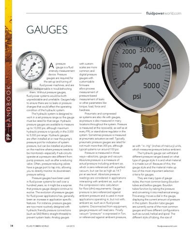
pressure gauge is a fluid intensity measurement device. Pressure gauges are required for the set-up and tuning of fluid power machines, and are indispensable in troubleshooting them. Without pressure gauges, fluid power systems would be both unpredictable and unreliable. Gauges help to ensure there are no leaks or pressure changes that could affect the operating condition of the hydraulic system. The hydraulic system is designed to work in a set pressure range so the gauge must be rated for that range. Hydraulic pressure gauges are available to measure up to 10,000 psi, although maximum hydraulic pressure is typically in the 3,000 to 5,000 psi range. Hydraulic gauges are often installed at or near the pump’s pressure port for indication of system pressure, but can be installed anywhere on the machine where pressure needs to be monitored—especially if sub-circuits operate at a pressure rate different from pump pressure, such as after a reducing valve. Often, pressure-reducing valves have a gauge port to tap into, allowing you to directly monitor its downstream pressure setting. Pressure gauges have been used in fluid power systems for well over a hundred years, so it might be a surprise that pressure gauge designs continue to evolve. The evolution of pressure gauges for fluid power applications has, generally, been an increase in application specific features. For instance, pressure gauges are now more routinely designed with hydraulic friendly pressure connections (such as SAE/Metric straight threads) to prevent system leaks. Analog gauges
psi
as with “in.-Hg” (inches of mercury) units, which measures pressure below ambient. The hydraulic gauge can withstand different pressure ranges based on what type of gauge style it is and what material it is made out of. Because of this, the gauge style and the material make up two of the most important selection criteria for gauges. They are many types of gauge styles, the most common being Bourdon tubes and bellow gauges. Bourdon tubes function by taking the pressure and converting it into mechanical energy. This energy moves a dial in the gauge, displaying the current amount of pressure in the system. Bourdon tube gauges are currently some of the most common gauges and have different configurations such as curved, helical and spiral. The different style of tubing, the size of fluidpowerworld.com
6/18/15 10:47 AM