20 minute read
Safety first — selecting the right position sensors for safety-related motion control


SAFETY FIRST
SELECTING THE RIGHT POSITION SENSORS FOR SAFETY-RELATED MOTION CONTROL
For safety-critical applications, motion control systems must be able to trust the position feedback that they receive from encoders and other sensors. If a sensor malfunctions, the controller must be able to quickly recognise the fault and take appropriate action.
Component failure can be detected more readily if there are redundant feedback channels in the control system. If the control system receives similar signals from two different sensors set up to measure the same mechanical property, it can reasonably assume that both are functioning properly. Discrepancies between the readings would signal a fault. This article discusses several strategies for implementing redundant feedback channels in motion control systems and weighs their relative strengths.
Enhanced safety through redundant feedback
For safety-related equipment, the motion control system should operate in a failsafe manner. That is, the system should be able to detect faults in the encoders and other sensors that provide position feedback and take appropriate actions to bring the machinery to a safe condition.
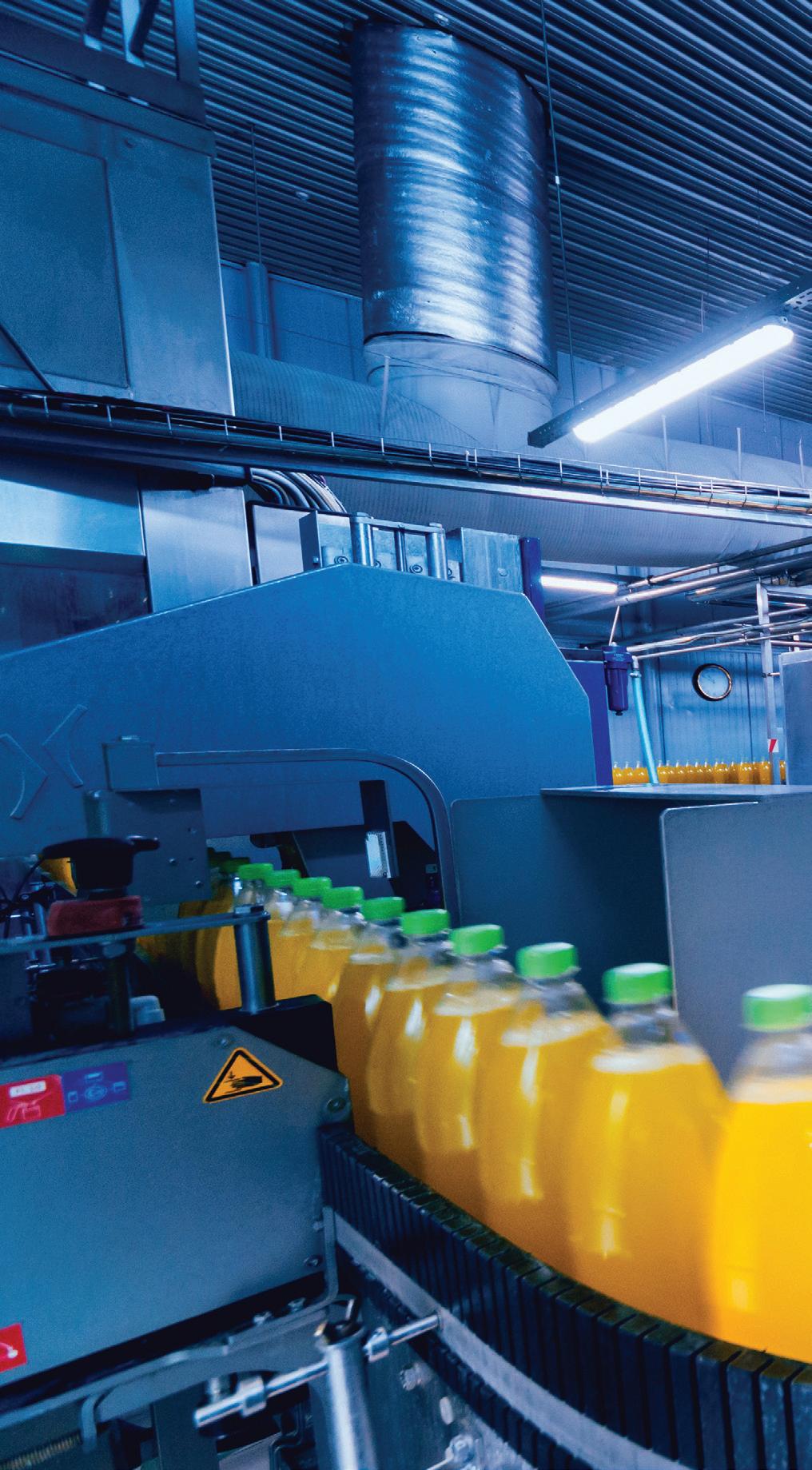
A widely used strategy for ensuring that information from a sensor is trustworthy is to build redundancy into the control feedback loops. For each safety-related action of the machine (such as rotation of an elevator’s cable drum, movement of a robot’s arm or extension of a crane’s boom), two or more semi-independent measurement systems would be installed to monitor the same mechanical motion. This enables the control system to detect sensor errors and avoid dangerous loss-of-control situations.
Duplicating each element of the feedback loop by adding extra encoders and communications cables will achieve this goal, but at the price of extra expense and increased mechanical complexity. The additional components will also take up valuable space in complex machinery.
©stock.adobe.com/au/romaset
About safety standards
Firstly, let’s briefly review safety standards.
There are several international standards that address functional safety in machinery or control systems, including: • IEC 61508: Functional Safety of Electrical/ Electronic/Programmable
Electronic Safety-related Systems. • ISO 13849-1: Safety of machinery — a safety standard which applies to machinery control systems that provide safety functions.
These standards address different areas of concern and are not always consistent in detail. There are, however, important common themes: • While absolute safety is impossible to achieve, including special design features (termed ‘safety functions’) can reduce risks to acceptable levels. • The need for special safety functions depends on both the probability of something going wrong and the potential consequences of an accident or failure. • To be effective, safety functions must meet reliability standards (performance levels or safety integrity levels) that are appropriate to the level of risks and consequences.
In ISO 13849-1, the level of reliability required for a safety function is defined in terms of a performance level, ranging from PL a to
PL e. If, for example, accidental malfunction could cause a serious injury to a person who frequently works close to a piece of machinery, the standard requires that the machine and its safety systems have a performance level of at least PL d. To achieve this performance level, MTTFd (mean time to dangerous failure), DC (diagnostic coverage) and Cat. (system architecture category) must all reach defined thresholds.
In IEC 61508, performance requirements are defined in terms of Safety Integrity Levels (SIL), ranging from SIL 1 (for situations with low risk and moderate consequence) to SIL 4 (high risk, serious consequences). SIL 2 is approximately equivalent to PL d and requires a similar level of reliability in safety functions.
Safety-certified encoders
An alternative approach is to use special safety-certified encoders. This type of encoder has two measurement modules installed in a single housing, sharing the same input shaft. A signal processing chip compares outputs from the two modules and — for most devices of this type — shuts down measurements and issues an alarm signal if a discrepancy is detected. Redundancy, in this case, is built into the encoder. Encoders with these characteristics can be designed to comply with Safety Integrity Level (SIL) or Performance Level (PL) standards.
An advantage of safety-certified encoders is that they can simplify the development of safety-critical systems. The control system will receive either reliable position data or a clear signal that the encoder has developed a fault. However, this approach can be inflexible when handling failure situations: if the sensors simply switch off, the control system has little guidance as to how to transition the machinery to a safe state.
Certified devices can also be significantly more expensive than ‘ordinary’ encoders largely because of the cost of certification by an independent testing laboratory. And, while these devices eliminate the need for doubling the number of encoders installed, they are only available in a limited number of mechanical configurations. Machine builders may be obliged to modify their designs to accommodate these sensors.
Diverse-redundant encoders
There is a new type of encoder that provides a middle ground between complex duplicate encoder installations and expensive safety certified devices. Diverse-redundant encoders have two measurement modules built into a single housing, sharing a common shaft. However, unlike their SIL or PL-certified counterparts, diverse-redundant encoders do not compare the output from the
two measurement channels. Instead, both output signals are transmitted directly to the controller (PLC, or control computer) to be evaluated there. This arrangement simplifies machine layout, since there is only one device to install for each control loop. And, since these devices are not formally certified, they are less expensive than their SIL-rated counterparts. They are also available in a greater variety of mechanical configurations.
An important feature of diverse-redundant encoders is that two different measurement technologies — optical and magnetic — are used for the two measurement modules. This improves diagnostic coverage and reduces the possibility of common cause failures. Both measurement systems are based on wellestablished encoder technologies designed to operate reliably over a wide range of temperatures. As well, both measurement channels feature battery-free multi-turn rotation counters for zero-maintenance operations. Diverse-redundant encoders are available with a wide range of mechanical options that include aluminium or zinc-coated steel housings, environmental protection up to IP66/IP67, multiple connector types and a variety of shaft and flange designs.
When using diverse-redundant encoders, the controller would ‘see’ two separate devices, measuring the same rotary motion. The controller is responsible for comparing the measurements and deciding whether they are reliable.
Does the lack of device certification put an extra burden on machine builders to prove the safety of their products? The answer depends on the complexity of the design. Even if certified components are used in the design, certification of the complete machine requires an end-to-end assessment of the design, including the way in which the control system handles component failure. Shifting responsibility for fault detection from the device to the controller may require only a minor increase in programming effort.
ISO13849 allows the use of non-certified redundant devices in safety applications, provided there is an end-to-end assessment of the design. By making the controller responsible for the verification of the two measuring channels, instead of the sensor, the designer has more flexibility in responding to the requirements of the application. If it is possible to determine which channel is faulty through a plausibility check, then the machine could be transitioned to a restricted operational mode, relying on information from the surviving encoder. If an impact analysis permits, the system can be kept running — possibly with manual override — until the faulty components are replaced.
©stock.adobe.com/au/romaset A WIDELY USED STRATEGY FOR ENSURING THAT
INFORMATION FROM A SENSOR IS TRUSTWORTHY
IS TO BUILD REDUNDANCY INTO THE CONTROL
FEEDBACK LOOPS.
Which approach is best for the application?
For simple systems with few motion control feedback loops, the use of duplicate, redundant sensors can be a cost-effective choice.
For one-off or low-volume products developed under tight time constraints, the convenience of working with SIL or PL-certified encoders (reduced development times, less safety knowledge required) might outweigh the extra cost and limited availability of these devices.
For many projects, diverse-redundant encoders can provide a best-of-both-worlds solution. There is only one device to mount on the machine, reducing complexity and space requirements. Meanwhile, the two independent measurement channels provide a sound basis for building machines that can be certified to Performance Level PL d, Cat. 3, according to ISO 13849.
With duplicate feedback loops or diverseredundant encoders, the control system might be able to use other system knowledge to make a reasonable assessment as to which of the redundant measurement systems is malfunctioning and whether the surviving system can be relied on to provide useful position data. In this case, the designer might be able to implement a restricted operating mode to extend the availability of the machine for a limited time. In any case, replacement of the defective device would be an urgent priority.
©stock.adobe.com/au/Alexey Seafarer
DIESEL TESTING UNIT FOR OPTIMAL ASSET PERFORMANCE
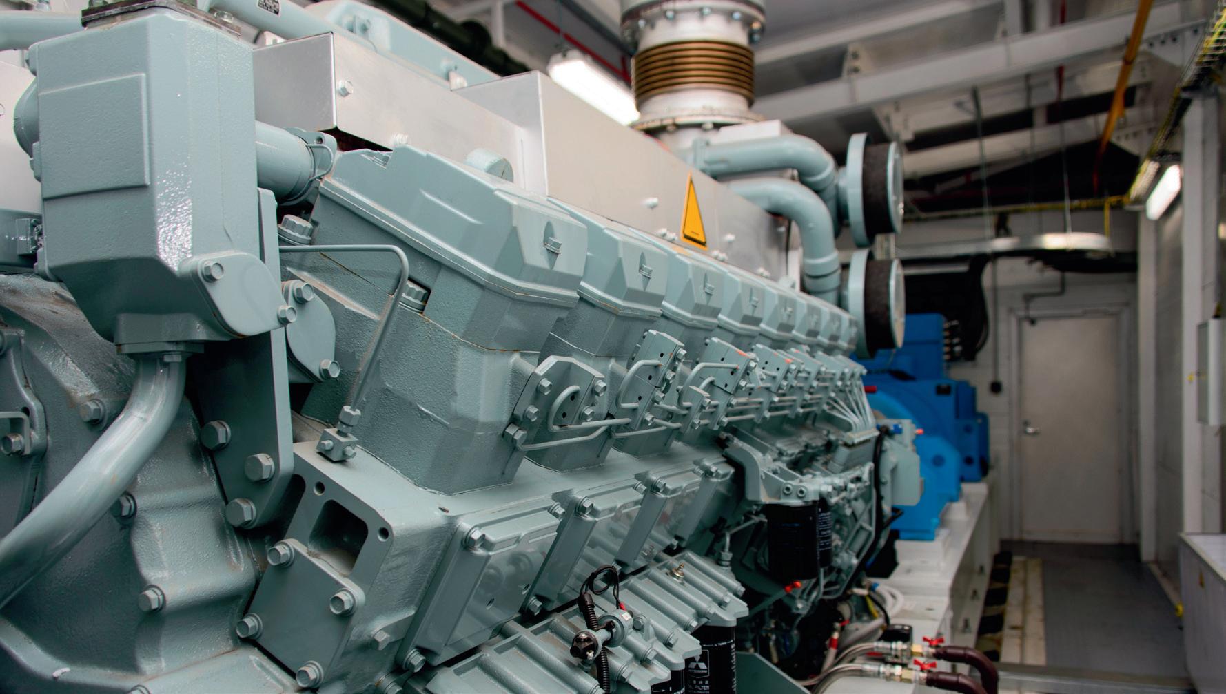
HYDAC recently completed a diesel testing unit for a technology and project development company focused on improving the reliability, effi ciency, and sustainability of assets, products, and processes to transform commercial performance.
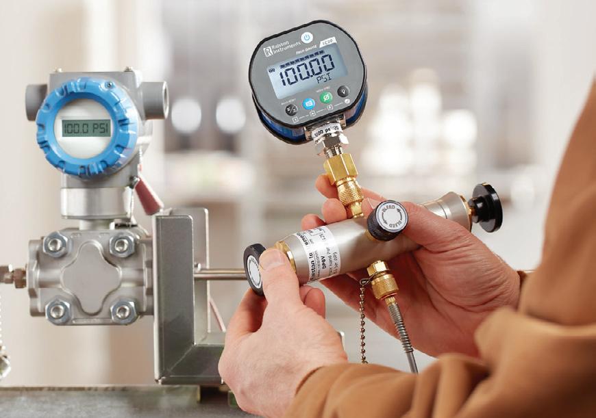
HYDAC Australia Project Engineer Kent Paulsen commented that the diesel testing unit is used to test diesel fuel injectors at a power plant. Features of the unit include a full range of sensors connected to a HMG 4000 data logging device, with the HMG 4000 programmed to convert the fl ow rate (L/min) measured by the EVS fl ow turbines to mass fl ow rate (kg/s) and an ability to achieve over 30 bar of pressure for a diesel system.
Full range of sensors connected to a HMG 4000
The HMG 4000 is a hand-held portable measuring and data logging device. HYDAC developed it for values measured in relation to hydraulic systems, such as pressure, temperature, fl ow rate and position.
“The customer was quite specifi c in terms of what data they wanted logged,” said Paulsen. “The testing unit monitors the supply pressure, fl ow, and temperature of the diesel going into the furnace. Then it monitors the return pressure, flow, and temperature as well. Additionally, we included a temperature transducer in the drain line. In total we had eight transducers all feeding back to the HMG 4000.”
He points out that normal analog sensors with 4–20 mA HSI output and HYDAC proprietary sensors/protocols were used.
“You can basically connect the HSI sensor to the HMG 4000 and you don’t need to program the parameters. It automatically recognises what kind of sensor it is and the sensing range, which makes life very easy on the ground,” he said. “We used one of those and then ran about eight sensors that all went back to the HMG 4000, which displayed all eight sensors at one time on a screen, with real-time information.”
Conversion of fl ow rate to mass fl ow rate
The HMG was also programmed to convert the fl ow rate (L/min) measured by the EVS fl ow turbines to mass fl ow rate (kg/s).
“This is very helpful to the end user or engineer who works in kilograms of diesel: they don’t measure in litres but in kilograms,” said Paulsen. “And the furnace will use their units of measurement in kilograms per second of diesel when it burns. That information on the HMG 4000 is much more useful to have as it eliminates the requirement of doing conversions later.”
Paulsen adds that the user can add any complex conversions or formulas to the HMG 4000 to aid in data logging.
“You can take two different sensors and the HMG 4000 can work out what the differential fl ow rate is between those two sensors,” he said.
Operation of a diesel fuel injector
Diesel fuel injectors have two different functions: the fi rst is to vapourise the diesel as it goes into the furnace for combustion, and the second is to ensure the diesel gets circulated through the injector to provide cooling.
“A power plant is run off a diesel furnace using the vapourised diesel supplied via the injectors,” he said. “A spin is imparted onto the diesel — like a centrifugal force — that gets it rotating quickly. This vapourises the diesel, making for perfect combustion conditions.
“Additionally, the injectors sit in the furnace and get hot as combustion occurs. The second function of the diesel testing unit was to provide cooling liquid that is circulated through the nozzle to prevent failure due to overheating.”
Collaborative approach
The group has extensive experience in the industry of power generation and manufacturing across the Asia-Pacifi c. Paulsen said the project started when HYDAC received “an enquiry along with a schematic” from the specialist engineering company in 2021.
“The customer had a good idea of what it wanted to execute and what it wanted from us,” he said. “We quoted in October and received the fi rst order for a unit at the beginning of November.”
Thereafter HYDAC commenced the design phase with a schematic and general arrangement for approval.
“The customer wanted additional back pressure valves in addition to other similar products for inclusion in the system. We had to undertake quite a few revisions, but this helped fi ne tune exactly what the customer wanted.
Paulsen emphasised that a collaborative approach “really works” because the customer can precisely convey what they want, enabling HYDAC to precisely meet its requirement.
“By the beginning of December 2021, we commenced procurement and fabricating, and the unit was assembled in February 2022: now that’s teamwork that gets the job done,” he concluded.
Tracking software for pallets, containers and more
Pallets, crates, containers, racks and tanks play a vital role in transporting goods. According to data from the Federal Statistical Office of Germany, approximately 101 million flat pallets — also known as Euro-pallets — were produced in Germany in 2020. But while the whereabouts of the goods are precisely recorded and tracked, to date, the load carriers themselves have received far less attention. They often remain unattended in warehouses for days, reducing efficiency.
At the Fraunhofer Institute for Material Flow and Logistics IML in Dortmund, researcher and logistics expert Dr Philipp Wrycza, together with his co-founders Patrik Elfert, Jan Möller and Michael Koscharnyj, have developed a suitable software solution and recently founded their own spin-off with the appropriate name ‘Logistikbude’, meaning “logistics convenience store”.
The web-based software first generates a label for each load carrier and creates a digital file. At the same time, returnable load carriers — pallets, tanks, racks, containers, crates — are equipped with barcodes or active sensors. A smartphone app available for Android or iOS records each load carrier via its label both before transport and when the goods arrive at their destination. It also allows further entries about their status to be made. This data is then immediately synced to the web-based software platform. In addition to tracking the load carriers by scanning them, there is also the option to record quantities.
The customer or recipient of the goods can also access the account and record, for example, when the goods have been unloaded and the pallets are ready to be returned or to transport other goods. In this way, a joint exchange account is created in which the business partners keep each other informed about the current status of the load carriers. If load carriers that have already been emptied have not been returned promptly, a reminder email is sent automatically. “Until now, many companies have often not even known where their own load carriers are at a given moment, for example,” Wrycza said. “Now they can see where they are at any time and when they will get them back. It makes planning easier, and the accelerated circulation ultimately ensures that fewer load carriers have to be purchased overall, contributing to increasing sustainability in the sector.” The software also helps avoid problems that regularly occur between business partners. For example, if a glass manufacturer loads their transport racks with windows and has them picked up by the carrier, they either receive the empty racks back straight away, or the haulage firm delivers the goods to the recipient and then returns the racks. However, misunderstandings and conflicts arise time and again; for example, if a rack is missing or if the recipient believes it is damaged.
The joint management of the load carriers helps to avoid errors and surprises from the outset. This is because the status and position of each individual load carrier can be viewed transparently. For example, the recipient can now record on the smartphone app if a rack arrives damaged. Companies that already have their own load carrier management also benefit from this solution. Previously, it has not been possible, or only possible at great expense, to dynamically track all these packaging materials during transit and seamlessly exchange data with business partners.
It is also possible to equip the load carriers with sensors. These can record values such as location, temperature or humidity and record them in the digital load carrier file. This would also allow them to provide information about the condition of food, for example.
The Fraunhofer researchers have made the software highly userfriendly. There is no need to customise the system. “We’ve allocated one day of training, and then the customer can get started right away,” Wrycza said.
Dr Volker Lange, head of Packaging and Retail Logistics at Fraunhofer IML, has supported the team’s work from the very beginning: “Our researchers have come a long way from the initial good idea to having a market-ready and cleanly functioning solution,” he said. “The spin-off now has the best prerequisites to successfully establish the solution on the market.”

DECENTRALISED I/O FOR Ex AREAS
Turck now has Ex approval for its TBEN-S and TBEN-L version IP67 block I/O modules to be used in Zone 2, enabling cabinet-free decentralised automation solutions with IEC Ex and ATEX approvals. This reduces labour costs as well as wiring and commissioning time. When used with IP67 IMC interface devices, it is now possible to have cabinet-free connection of intrinsically safe signals from Zone 0 or 1. Users must install the TBSG-L, TBSG-S or IMC-SG protective housings when implementing the I/O modules in Zone 2. They provide protection against shock and from sparks caused by unsafe removal of cables. The range of applications with Ex zones includes painting, bottling or pharmaceutical plants as well as food industry and wood processing plants. The ARGEE field logic control software in the I/O modules enables self-contained applications to be implemented directly in Zone 2. This is particularly useful for retrofit applications because existing controller systems do not have to be changed. Condition monitoring and data analysis via cloud systems can now also be implemented from Zone 2 without the need for a control cabinet.

Turck Australia Pty Ltd
www.turck.com.au
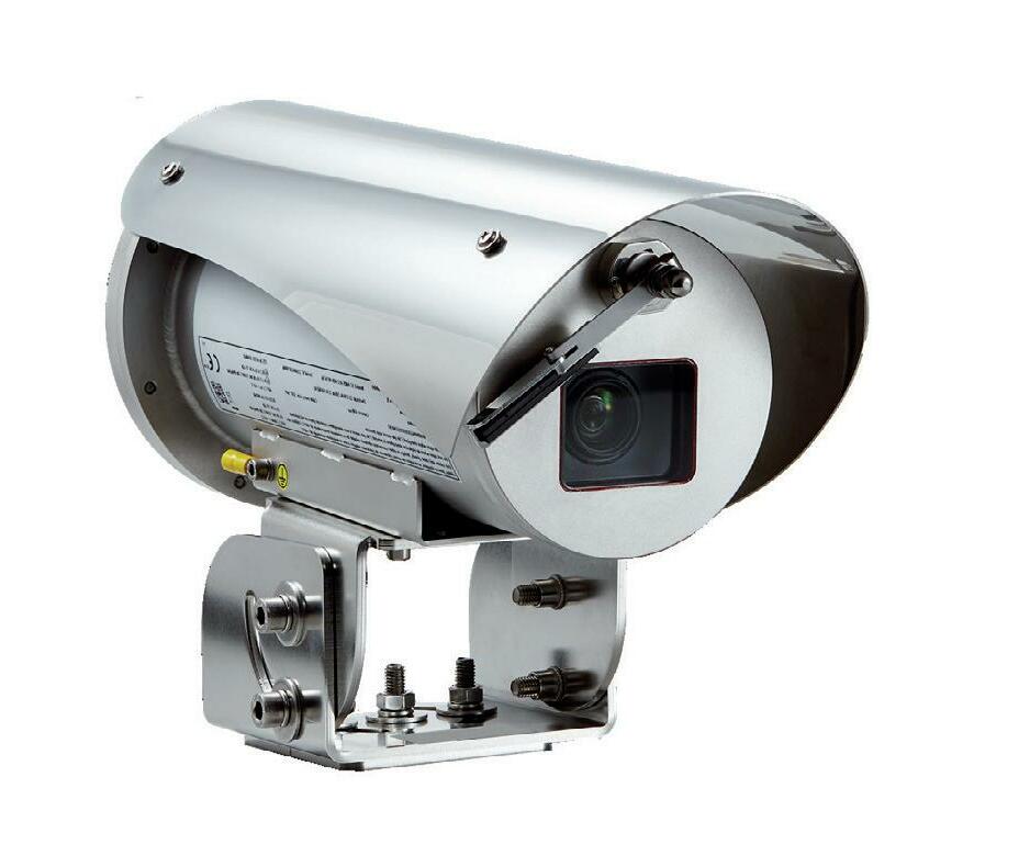
INDUSTRIAL EVENT CAMERA
The Pepperl+Fuchs VOC industrial event camera allows event-driven video recording up to 60 s before and after a trigger signal, therefore enabling targeted and simple remote diagnostics as well as automatic documentation. If a malfunction, a predefined state or process occurs, the trigger initiates the video recording.
In an automated parking garage, for example, every parking process should be documented in order to quickly and easily prove the condition of the vehicle in the event of liability. The recording starts every time a new vehicle enters the parking garage. Due to the automatic timestamp and the UDP interface for dynamic text overlays, users can find the files quickly and easily. As soon as an event activates the trigger, the camera generates and saves a video recording as a permanent data record, which can contain up to 60 s before and after the trigger signal. The integrated circular buffer is cyclically filled with the image recording.
By recording only relevant situations, the amount of stored data is kept to a minimum. The data is stored on a local, exchangeable SD card with a capacity of 8 GB. Compared to 24-hour video recording, no complex data integration or PC hardware is required. Depending on the pre-set resolution, length and quality of the sequence, the event camera can store up to 10,000 events on the card. Video recordings can also be automatically deleted at a set point in time or the oldest overwritten when the memory is full.
Pepperl+Fuchs (Aust) Pty Ltd
www.pepperl-fuchs.com
DEWPOINT HYGROMETER
Michell has developed the Easidew Advanced Online dewpoint hygrometer as a versatile, high-performance hygrometer system. Incorporating the latest ceramic metal-oxide technology, the hygrometer is said to provide stable, reliable and repeatable trace moisture measurements. It also features an easy-to-use touch screen interface for set-up and operation.
Because pressure is such an important variable when measuring the dewpoint of a gas, the hygrometer compensates for this with either a live pressure sensor input or by using a fixed pressure input value. The Easidew Advanced Online can be used for any moisture measurement application, displaying data in °C or F dewpoint, ppmV, lb/mmscf or g/m3 from -110 up to +20°C at pressures up to 450 bar (6627 psi).
Additionally, the hygrometer provides analog, digital and four user-configurable alarm outputs. As well as the 4-colour display, the hygrometer can be configured remotely via application software.
Regular maintenance and recalibration are essential to ensure ongoing reliability and users have two options to achieve this with minimum disruption. The sensor exchange program is designed to eliminate process downtime: users order a guaranteed, reconditioned sensor and, when this arrives, replace and return their old sensor.
Where traceability of calibration is needed, Michell offers a recalibration service at one of its regional calibration laboratories.
The Easidew Advanced Online Hygrometer is suitable for a wide range of trace moisture measurement applications, such as: surgical and medical air; glove boxes; hydrogen refilling stations; pharmaceutical manufacturing; and membrane and adsorption dryers.
AMS Instrumentation & Calibration Pty Ltd
www.ams-ic.com.au


THREE-WAY BALL VALVE
The 543 ball valve from GF Piping Systems has been a durable and flexible solution used for mixing and distribution in applications ranging from water treatment to complex chemical and pharmaceutical processes. GF Piping Systems is now introducing the 543 Pro ball valve, which is designed to improve usability, adding sensors and actuators that offer new possibilities for process automation.
The 543 Pro three-way ball valve increases safety with a lever that prevents unintentional operation due to the addition of a locking ring. For an extra layer of security, a padlock can also be fitted in order to protect the valve against unauthorised use. In addition, the accessories include a manual spring return unit that ensures that the valve closes automatically when it is released. Another feature for the 543 Pro is the addition of new stems with a predefined breakpoint between the actuator and ball valve. In the event of a blockage within the system, the breakpoint ensures that only the stem has to be replaced rather than the entire ball valve.
The 543 Pro features a retrofittable position feedback sensor with an LED display that records the position of the control lever. The compact double sensor can be easily mounted with a snap-on design. In addition to traditional manual operation and a pneumatic control unit, the ball valve can be operated fully automatically with an electric actuator. The 543 Pro also features a scannable Data-Matrix-Code which simplifies the storage of all component information and enables individual traceability.
GF Piping Systems
www.gfps.com/au

FREE
to industry and business professionals
The magazine you are reading is just one of 11 published by Westwick-Farrow Media. To receive your free subscription (magazine and eNewsletter), visit the link below.