
Portfolio 2019 2023 Selected Works
Vora
Vidhi
Vidhi Vora

Graduate Student Architectural Designer
+1(857) 746-8262 | voravidhi.96@gmail.com | Allston, Boston MA-02134

+1(857) 746-8262 | voravidhi.96@gmail.com | Allston, Boston MA-02134
During my early school days, I was a very active student who used to get immense joy and satisfaction in art and crafts such as shapes and forms, sketching sceneries, painting, and drawing. I was very much interested in studying different historic buildings and monuments. This interest grew into fascination during high school when I visited construction sites with my father, a builder, and real estate agent. I got the opportunity to interact closely with people in the architecture and construction field. He always told me, “Buildings are not only a place to reside but an art built to dreams.” While exploring the city with him, I wondered how every space built affected different diversities of people with varying living standards.
At that early stage, I was intrigued by grand buildings that would change a city’s skyline, and since then, my will has been to improvise and uplift the current standards that are set and are often ignored in the field of Architecture. All these thoughts constantly tingled my mind, which made me believe in pursuing a degree in Architecture. In my initial years, the course of study taught me to design basic structures considering minor elements like fenestrations in the facade and significant features like light optimization, environmental effects, structural mechanics, and context design. I realized that each structure is built to react according to the climate, local materials, visual stance, culture, and the users of the place. The experiences from my academic and professional years gave me insights into the relationship between a building’s space and its functionality.
Experience
Designer 1 - Internship
Timothy Burke Architecture / Boston, MA / Feb’2023-May’2023
• Modernized residential interior and multi-housing projects, gaining a deeper understanding of space planning and optimization by ensuring efficient use of square footage.
• Created functional layouts considering zoning regulations, accessibility requirements, building codes, and by-laws.
• Generated architectural document sets including schematic proposals, detailed design development, construction drawings, and representation drawings by incorporating company standards and project goals.
Junior Architect
Connect Four Design Studio / Mumbai, INDIA / Jan’2020-April’2022
• Designed complex corporate office and commercial interior spaces by creating cohesive interior and exterior design schemes that become flexible workspaces, allowing for future expansions, changes in layout, and evolving business needs.
• Grew significant knowledge in project management by handling a corporate complex project, coordinating with seniors and multi-disciplinary teams.
• Developed a keen eye for detail and quality control to maintain a high standard of design throughout the construction phases.
Internship
Geopreneur Design Group / Mumbai, INDIA / Nov’2017-March’2018
• Build high-end residential interior design schemes by balancing functionality with the client’s desired aesthetic while ensuring all materials and appliances performed well under the building code specification.
• Gained a deeper understanding of client interactions and communication skills.
Education
Graduate Student: Masters of Architecture
Boston Architectural College / Boston, MA.
Completed: Bachelors of Architecture
2022 - Present
2014 - 2019
Thakur School of Architecture and Planning/ Mumbai, INDIA.
Interpersonel Skills
Communication Skills
Conceptualization
Design Development
Teamwork
Leadership qualities
Creative skills
Accustomed to Heavy Workload
Professional Skills
Revit
AutoCAD
Sketchup
MS Office
Design Interests
Residential Design
Commercial Architecture
Assembly Buildings
Interior designing
Urban Planning
Product Designing
Photography.
Lumion
Enscape
Adobe InDesign
Adobe Photoshop
Academic Work M.ARCH STUDIO WORK | 2023
School of Crafts, Roxbury ma | Pg 04-11
Community Sailing Center, Portland Maine ma | Pg 12-19
B.ARCH THESIS | 2019
Multifunctional Library, Pune India | Pg 20-25
Practical Experience
TIMOTHY BURKE ARCHITECTURE | 2023
28 Hanson St, Boston ma| Pg 26
692 Washington St, Brighton ma| Pg 27
78 Upland Road, Brookline ma| Pg 28-29
84 Parker St, Westwood ma| Pg 30-31
CONNECTFOUR DESIGN STUDIO | 2020-2022
MFAR Silicon Forest, India | Pg 32-35
MFAR Primrose Road, India | Pg 36-38
Pg 39
Studio 4- M’Arch
This project provides the ability to explore the concepts in the design of a new School for Craft in Roxbury. The school will be a hypothetical independent organization serving two significant functions: supplementing the vocational curriculum of Madison Park Technical Vocational High School, part of the Boston Public School (BPS) system, and as a provider of short-duration adult education and fulltime programs, similar to the North Bennet Street School (NBSS). Vocation and job training are a critical part of community growth, and this project is an opportunity to provide additional community resources to the Roxbury neighborhood, of which Madison Park (the only vocational school in the BPS system) is a part.

FAR, SETBACKS, REQUIREMENTS
District designation Zoning District: ROXBURY NEIGHBORHOOD


Overlay District(s): NONE
Spaces Per 1,000 Square Feet of Gross Floor Area: 1.0

FAR: 2.0 x Lot area (sq.ft.): 47000 = 94000 max. gross sq.ft.

Setback Requirements Zoning Section / page:

a) Side 1: NONE
b) Side 2: NONE
c) Rear: 12 ft
d)Front: NONE
e) Max. Height: 65 ft
f) Easements- NONE
Weaving Nodes Connecting Nodes and Lines to Scoop Polygonal Forms

Directionality Derived to Create Experience Within the Site and Building Bifurcating the Spaces in Public and Private Zones


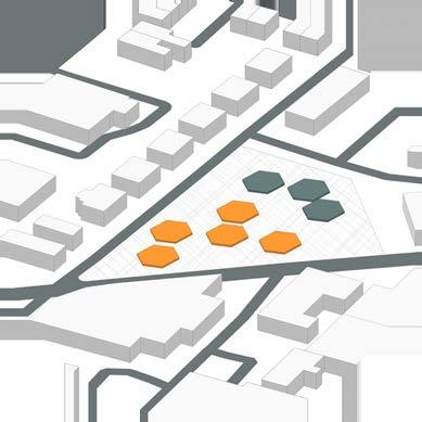


Overlapping of Forms Like Interrealed Functions Cultivating Green Pockets Engaging the Community Around


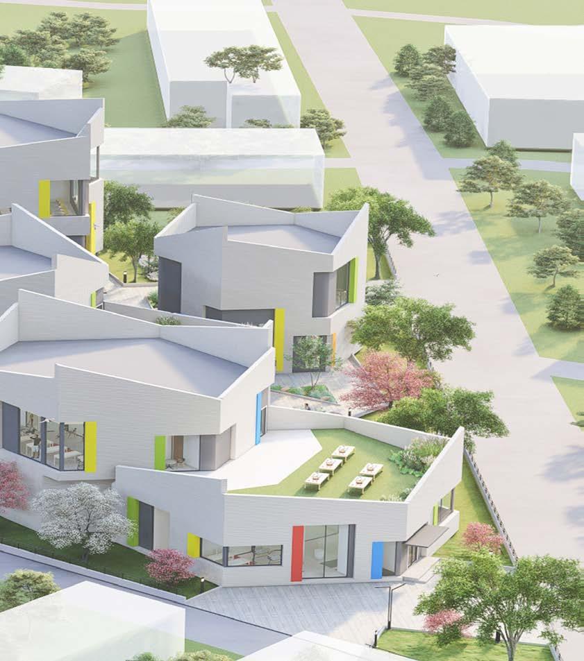
Volumetric Play with Different Glazed Windows


Internal Passages with Transparent Partition Walls


Choosing this system will provide the building with more floor-tofloor heights as this design has several workshops. Additionally, it is cost-effective and flexible with internal partition wall types. Since the building has heavy workshops, it will provide sound insulation from heavy machinery. Another design advantage is that Flat slabs can create clean, modern lines and a minimalist aesthetic build form and can be finished in various textures and colors, allowing for different design options.
For the school for crafts, using a flat slab system with a drop panel system offers structural efficiency, flexibility in space design, increased ceiling height, improved thermal comfort, simple installation of building utilities, cost-effectiveness, simplicity of maintenance, adaptability, and adaptability. These benefits complement the school’s aim of promoting crafts education by helping to create a pleasant, practical, and flexible learning environment for the students.


STAIRCASE
HVAC DUCT
ELECTRIC DUCT
SERVICES AREA


WET AREA
FRESH AIR
RETURN AIR
PLUMBING
Studio 3- M’Arch
This project provides the ability to explore the concepts in the design of newer strategies for resilient structures. It caters to the students of Sail Maine by providing them with a space to learn and explore sailing by designing a new community sailing center in the city of Portland.
This was a group project done along with 2 of my colleagues, and our goal was“By providing Resilient strategies, the design seeks to create opportunities for people regardless of age, ability, or means, to engage in a Community Center and Recreational Sailing facilities; All while providing access to water and green spaces.”


Climate Change
Lack of community Spaces


Increasing Sea Water Level

Adoption of Constructed Ground Stratergy as Resilient factor

Connection of Comunity to Harbour By Breaking the Hard Edge


Goal of Environmental Conservation By Using Various Building Systems.


The community sailing center has implemented three innovative building systems: a rainwater retention system, a floating island system, and a wood-glass enclosure system.


• Rainwater Retention system:- The sailing center’s rainwater retention system is intended to collect and store rainwater in various ways. The sailing facility promotes water conservation and lessens its dependency on outside water sources by putting this system in place.
• Floating Island system:- The floating island concept is a sustainable way to improve the community sailing center’s waterfront space. It entails constructing artificial floating islands, usually built from buoyant materials and covered in flora. This approach encourages biodiversity, improves the condition of the water, and improves the sailing center’s overall aesthetics.
• Structue- Enclosure system:- With the help of this approach, you may design rooms that are both aesthetically pleasing and useful. Glass is used to allow for abundant natural light and to provide panoramic views of the surrounding environment, including the waterfront and sailing activities. Wood is used for its natural warmth, aesthetic appeal, and sustainability.


A library is a vital medium for human education. It stands as the most substantial base for transmitting mass education and awareness. I conceptualized and designed a public library in Pune for my final year thesis design. The focus was to re-image and re-invent a stereotypical library space. Today, libraries have become social agencies and also institutes. Modern libraries satisfy general public information needs by providing all kinds of knowledge and information available to all community segments regardless of race, caste, creed, society, age, gender, religion, nationality, economic, and employment status. Today, a public library is a perfectly moral and mental development center. Its doors are always open for all the people of society. It should also provide other community services, such as storytelling for children, after-school programs, language learning, seminars, workshops, and other community services.

Pune is Maharashtra’s cultural and educational capital, also known as “The Oxford of the East.” It is not just the proximity to India, Mumbai’s industrial, commercial, and financial capital. Still, it prides itself on being close to the richness of the country’s culture. Located in the Sahyadri Hills, near the west coast of India, in Maharashtra, Pune is a fascinating city with a good climate that suits everybody all year round. Referred to as the ‘Queen of Deccan,’ Pune is located 170 km south of Mumbai. Yerawada is a neighborhood of the city of Pune in the state of Maharashtra, India.
Yerwada is one of the most densely populated areas in Pune.

It’s on the campus near Deccan College, surrounded by 12 m wide roads on two sides. Adjacent Roads to the site are Dr. Ambedkar Path and Alandi Rd. A Bus Transit System (BRTS) is about 300 m from the site (i.e., just next to the site), which creates an easy source of accessibility for all. Nearby places to Yerawada are Koregaon Park, Magarpatta City, and Shivaji Nagar, which are areas of Mixed-use Development.

This particular site was selected to provide a nurturing environment to visitors by pushing the barriers of traditional education. Based on the visit to Pune, the public spaces for knowledge and recreation needed to be improved, which could benefit students and cooperation, people, hence site near colleges and commercial hubs was one of the most important criteria.


“To understand the role of a public library not only as a storage of books for individual development but also in terms of community growth.”

The overall site plan development was done according to the surrounding site context and considering the climatic conditions of Pune, Maharashtra. The plot was divided into segments which formulated different build spaces. These spaces were interconnected to develop areas with other functions to be conducted at different times. A single entrance led to an open plaza, which created a welcoming environment for a public educational building. This plaza directed the crowd into the main administration building. Further, the admin block took the public towards two different buildings - the Conventional Library and the Semi-Public Reading building.

The central Conventional Library had different sections used for material and digital studying. Each team was divided according to other age groups, yet it provided a shared space for them to share knowledge and life experiences.
The Semi-Public Reading Building was built with the concept of inviting students and the community to come and read/ study from their study materials like books/laptops. Most cities usually need more to provide open spaces.
Hence this area would encourage group discussions among students. A seminar hall was also designed for author-book reading sessions or awareness seminars. Hence, this library was designed to re-invent & re-imagine the outlook towards public libraries in our country.


Exploded Isometric

Main Library with Huge Windows
Multi purpose Conventional Spaces
Double Height Reading gallery and Study Carrels


I did the condo Set for 28 Hanson Street during my tenure at TBA. I studied the zoning and building regulations specific to condominium development in Boston. While noting down the setback requirements, height limitations, parking regulations, and any other relevant guidelines, I started with field measurements of the project. By drafting the plans for approval, I kept all the present measures and old permit documents to evaluate and produce final detailed floor plans for each unit that depict room dimensions, locations of walls, doors, windows, and any built-in fixtures. I ensured that the drawings accurately represented the proposed layout and design.
28 Hanson Street, Boston Timothy Burke Architecture, 2023.
I started this project in my initial month at TBA, during which I visited the existing house in Brighton with my seniors for field measurements. We imagined and discussed some design ideas for renovating this into a 6-unit home. I then crafted the initial layouts in Revit and produced a detailed existing house in 3D. Gradually we finalize a few alternatives according to the relevant guidelines and character of the surrounding neighborhood. We tried to design these unit configurations to be efficient, functional, and appealing to potential residents. Two finalized options are listed below; these are typically first-floor layouts; similarly, other floors were developed.
692 Washington Street, Brighton Timothy Burke Architecture, 2023.
Developing multiple lot options was a great learning experience at TBA. I studied and familiarized myself with the zoning and subdivision regulations specific to this area in Boston, where the lot division was to take place. The client needed his existing lot divided into two properties and wanted to build a new house on the new lot. My supervisor and I assessed the characteristics and constraints of the current lot, such as its size, shape, topography, and any existing structures or features. Further, I developed a neighborhood plan locating the nearby housing typologies. We even consulted with a professional land surveyor who can accurately measure and map the existing lot boundaries, utilities, and easements or encroachments.
During the initial phase of planning alternatives, we ensured that each divided lot had adequate access and circulation and that access points complied with transportation regulations and safety requirements. We designed it keeping in mind that the proposed lot division options can be adequately serviced by existing or planned infrastructure, and more open/green spaces are being provided to each lot, as shown in the choices below. After multiple options, we proposed these three options to the client and discussed them with local authorities, planning departments, and zoning officials to ensure compliance with all applicable regulations and requirements specific to Boston.
We defined the goals and objectives of the renovation project by developing detailed drawings for the house in Westwood. This set included proposed floor plans, demo plans, electrical layouts and schedules, overall elevations and internal elevations. We designed the second floor of this house and also produced drawings for the changed sidings and new windows on the exterior walls.
I studied regulations and different market product cataloges for choosing various electrical and interior details that included staircase parts, windows, furniture, etc. Designing the electrical layout was important at this stage, which allowed the finalisation of the budget for renovation. I majorily learned revit as a BIM tool during this project and my time at TBA.
The project was done during the second year of my professional work period at ConnectFour; when, I understood the importance of building adequate architectural spaces. I have primarily been a part of this project, from compiling design intents to detail drawings that went to and fro between the consultants and us. This project is a commercial multi-storey office complex in Bangalore, India. The primary purpose of the master plan was to narrow down the style and aesthetic of the project. Since master planning involves developing a framework for the entire structure, it also defines every structural detail. Typically, we as architects worked with our teams to outline the design scope of the project.
During this process, I, along with my team, took into account all aspects of the project, including budgetary, structural requirements, shapes, views, and other design options.
The master plan involved design information for uses, heights, and setbacks depending on the project. We recognized that workers are more productive within a collaborative environment that establishes interaction and a sense of community. Our focus on the experience created through active public spaces, engaging amenities, and flexible, adaptable tenant spaces delivers office space that predicts the expectations of a demanding tenant demographic.


As a designer, my role was to develop multiple testfit options for all the wings of this project. I developed these considering the Code requirements for a unit floor plate to the number of users to achieve premium and usable office spaces.
During the test fit process,the program is assesed with basic square footages and these verify the current requirements with the future tenant and test if all of the components fit within the space. The test fits verifies that required adjacencies are maintained throughout the space – for examples executive conference rooms located near the executive offices.
FIT LAYOUTS (1500 X 600 WORKSTATIONS)
As the team at Connect Four we have used master planning in our projects, that have noticed significant improvements. The process allows us to manage our projects with extreme precision. It also affords us considerable flexibility throughout the entire duration of design and construction. Our principals understand the importance of master planning and use it as our first line of attack for every project we work.
In developing countries like India, the development projects could be planned in a much more integrated and efficient manner responding to project specific challenges.

My part in this project was to graphically model and represent design ideas designed by another team from my workplace. These illustrations were made to design another mixed-use commercial building in Bangalore. I participated in modeling the project and incorporated different materials sustainably suitable. Many proposals went through and fro for creating external facades and some internal spaces like reception areas, canteen, and library. Each proposal compilation into a detailed presentation was another role I played during this project. Some of the drawings included rendered floor plans, sectional drawings, elevation drawings, and three-dimensional views.
We kept in mind the next generation using the office space as we designed. Design strategies were used that purchased energy (like electricity and natural gas) to keep buildings active and comfortable. These strategies included mechanical system components such as heat pumps, air-conditioning, radiant heating, electric lighting, and heat recovery ventilators. All in all, defining these aspects of the program helped eliminate the design options and narrowed the focus.
Modern mixed-use development is usually considered a way to rejuvenate communities by creating spaces where a considerable communal part gathers to work, live and shop. The social benefits of mixed-use development extend far beyond enhancing. With the popularity of walkable urban environments on the rise, more developers are turning to mixed-use projects, usually bringing together some combination of office, housing, and shops, sometimes with accommodation or community-serving uses. Local businesses can also benefit from the synergy that mixed-use development provides. With proximity to nearby amenities such as restaurants and fitness centers, employers can showcase their convenient location for potential employees, clients, and business travelers. Mixed-use developments also support local governments with significantly higher returns through property and sales taxes.


“Dont Shoot What It Looks Like, Shoot What It Feels Like.” - David Alan Harvey


