RCD selection table according to their sensitivity: AC type
A type
B type
•
•
•
No response
•
•
No response
No response
•
U U U
U
t t t
U U
U
t t t
U U
t t t
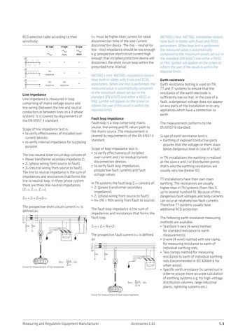
Line impedance Line impedance is measured in loop comprising of mains voltage source and line wiring (between the line and neutral conductors or between lines on a 3-phase system). It is covered by requirements of the EN 61557-3 standard. Scope of line impedance test is: • to verify effectiveness of installed over current devices; • to verify internal impedance for supplying purpose. The line-neutral short circuit loop consists of: • Power transformer secondary impedance ZT, • ZL (phase wiring from source to fault), • ZN (neutral wiring from source to fault). The line to neutral impedance is the sum of impedances and resistances that forms the line to neutral loop. In three phase system there are three line-neutral impedances (ZL1-N, ZL2-N, ZL3-N). ZLN = ZL+ ZN+ZTLN The prospective short circuit current IPSC is defined as:
IPSC must be higher than current for rated disconnection time of the over current disconnection device. The line – neutral (or line - line) impedance should be low enough e.g. prospective short circuit current high enough that installed protection device will disconnect the short circuit loop within the prescribed time interval. METREL’s hint: METREL installation testers have built-in tables with fuses and RCDs parameters. When line test is performed, the measured value is automatically compared to the maximum values set out in the standard (EN 61557) and either a PASS or FAIL symbol will appear on the screen to inform the user if the result is within the required limits. Fault loop impedance Fault loop is a loop comprising mains source, line wiring and PE return path to the mains source. The measurement is covered by requirements of the EN 61557-3 standard. Scope of loop impedance test is: • to verify effectiveness of installed over current and / or residual current disconnection devices; • to verify fault loop impedances, prospective fault currents and fault voltage values. In TN systems the fault loop ZL-PE consists of: • ZT (power transformer secondary impedance); • ZL (phase wiring from source to fault); • RPE (PE / PEN wiring from fault to source). The fault loop impedance is the sum of impedances and resistances that forms the fault loop. ZLPE = ZL+ RPE+ZT The prospective fault current IPSC is defined as:
ULN >Ia IPSC= ____ ZLN
Circuit for measurement of line impedance
ULPE >Ia IPSC= ____ ZLPE
METREL’s hint: METREL installation testers have built-in tables with fuses and RCDs parameters. When loop test is performed, the measured value is automatically compared to the maximum values set out in the standard (EN 61557) and either a PASS or FAIL symbol will appear on the screen to inform the user if the result is within the required limits. Earth resistance Earth resistance testing is used on TN, TT and IT systems to ensure that the resistance of the earth electrode is sufficiently low so that, in the case of a fault, a dangerous voltage does not appear on any parts of the installation or on any appliances which have a connection to earth. The measurement conforms to the EN 61557-6 standard. Scope of earth resistance test is: • Earthing of exposed conductive parts assures that the voltage on them stays below dangerous level in case of a fault. In TN installations the earthing is realized at the source and / or distribution points that’s why the earthing resistances are usually very low (below 1Ω). TT installations have their own main earthing. The resistances are usually higher than in TN systems (from few Ω up to several hundred Ω). Because of this dangerous fault voltages and body currents can occur at relatively low fault currents. Therefore TT systems usually have additional RCD protection. The following earth resistance measuring methods are available: • Standard 3-wire (4-wire) method for standard resistance to earth measurements; • 3-wire (4-wire) method with one clamp, for measuring resistance to earth of individual earthing rods; • Two clamps method for measuring resistance to earth of individual earthing rods (recommended in IEC 60364-6 for urban areas); • Specific earth resistance (is carried out in order to assure more accurate calculation of earthing systems e.g. for high-voltage distribution columns, large industrial plants, lightning systems etc.).
Circuit for measurement of fault loop impedance
Measuring and Regulation Equipment Manufacturer
Accessories 1.61
1. 3


